service and repair manual - helac
TRANSCRIPT

L10 SERIESService andRepair Manual
HELIC
AL H
YD
RA
ULIC
RO
TAR
Y A
CTU
ATOR
S
2 Helac Corporation
Table of Contents
Introduction
Table of Contents .................................................................................................................................. 2
Product Introduction .............................................................................................................................. 3
General Safety Guidelines .................................................................................................................... 4
Product Identification ............................................................................................................................ 4
Theory of Operation .............................................................................................................................. 5
Tools
Tools Required ...................................................................................................................................... 6
Drawings
Assembly Drawing ................................................................................................................................ 7
Exploded View ...................................................................................................................................... 8
Spare Parts .......................................................................................................................................... 9
Parts List .............................................................................................................................................. 9
Protective Sleeve .................................................................................................................................10
Disassembly
Before Disassembly .............................................................................................................................11
Disassembly .......................................................................................................................................11
Inspection ............................................................................................................................................15
Assembly
Seal and Bearing Installation................................................................................................................16
Assembly ............................................................................................................................................19
Post Assembly
Grease Thrust Washers .......................................................................................................................23
Testing the Actuator ............................................................................................................................24
Installation and Bleeding ......................................................................................................................25
Troubleshooting Guide .........................................................................................................................28
Warranty Information ............................................................................................................................29

3Helac Corporation
Product Introduction
For over 30 years, Helac Corporation has beenrecognized for innovation in design of hydraulicrotary actuators and construction equipmentattachments. Helac products are known for theirtremendous torque output, compact configurations,exceptional load bearing capabilities, and rugged,reliable performance.
Over 1,000 mobile, industrial, construction andmining machinery manufacturers around the worlddepend on Helac actuators to perform suchfunctions as rotation, positioning, manipulation,vehicle steering and indexing. Helac's L10 Seriesrotary actuators are used widely on utility aerials(basket rotation), rock drills (drill rod magazinerotation), industrial vehicles (steering), robotic
equipment (joint movement) and jib cranes (boomrotation), along with many other positioning, liftingand processing applications.
All L10 Series actuators incorporate the sameinternal design, though they vary in size dependingon model.
Many actuators are equipped with a factoryinstalled counterbalance valve, which performs threemajor functions.
• Protects the actuator in the event of overload
• Prevents drifting of the actuator and theassembly/component mounted to it
• Keeps the actuator pressurized in a holdingposition to reduce hydraulic backlash

4 Helac Corporation
General Safety Guidelines
Many actuator applications have several pinchpoints with the potential for severe injuries.Use extreme caution and remain clear of allrotating components whenever the machine isin operation.
Each Helac actuator is individually serial numbered.The serial number is a five or six digit number andmust be provided before parts and/or service issuescan be addressed.
The serial number can be found on the Identification(ID) Tag that is affixed to all actuators. The tag is athin, silver colored, plastic label with a self-adhesivebacking. Information is imprinted in black. The tagis located on the housing tube of the actuator. Insome cases, the ID tag may be painted over by the
OEM (Original Equipment Manufacturer).
Additionally, the serial number of the actuator isstamped onto the housing tube. It may benecessary to remove paint to expose the serialnumber.
If the ID tag is not attached to the actuator and/orthe stamped serial number cannot be located, thebasic actuator model can be identified bymeasuring the outside diameter of the actuator.
Product Identification

5Helac Corporation
Theory of Operation
The L10 Series rotary actuator is a simple mechanismthat uses Helac's sliding spline technology to convertlinear piston motion into powerful shaft rotation. Eachactuator is composed of a housing with an integral ringgear (1) and only two moving parts: the central shaftwith an integrated bearing and mounting flange (2),and the annular piston sleeve (3).
Helical spline teeth machined on the shaft engagematching splines on the inside diameter of the piston.The outside diameter of the piston carries a secondset of splines, of opposite hand, which engage thematching splines of the housing's ring gear.
As hydraulic pressure is applied, the piston isdisplaced axially within the housing - similar to theoperation of a hydraulic cylinder - whilesimultaneously, the splines cause the shaft to rotate.When the control valve is closed, oil is trapped insidethe housing, preventing piston movement and lockingthe shaft firmly in position.
The shaft is supported radially by the large upper radialbearing and the lower radial bearing. Axially, the shaftis separated from the housing by the upper and lowerthrust washers. The end cap is adjusted for axialclearance and locked in position by set screws or pins.
Bars indicate starting positions ofpiston and shaft. Arrows indicatedirection they will rotate. Thehousing with integral ring gearremains stationary. For clarity,the shaft flange, bearings, andend cap are not shown.
Applying fluid pressure willdisplace the piston axially whilethe helical gearing causes thepiston and shaft to rotatesimultaneously. The double helixdesign compounds rotation:shaft rotation is about twice thatof the piston. Applying pressureto the opposite port will returnthe piston and shaft to theiroriginal starting positions.
3
2
1

6 Helac Corporation
Tools Required
1. PIPE VISETo secure the actuator to the work bench.
2. SAFETY GLASSES
3. FLASH LIGHTHelps in locating and examining timing marks,component failure and overall conditions.
4. RUBBER MALLETRemoval and installation of shaft and pistonsleeve
5. STRAP WRENCHUsed to turn the piston onto and off of the shaft
6. HEX WRENCH SETRemoval and replacement of port plugs and setscrews (106,110).
7. PRY BARRemoval of end cap and manual rotation of shaft.
8. ASSORTED SCREWSRemoval and installation of shaft and pistonsleeve.
9. TORQUE WRENCHUse when achieving certain torque specifications.
10.FELT MARKERMakes timing marks and outlines troubled areas.Permanent ink is recommended.
Several basic tools are required for the disassemblyand the assembly of the actuator. The tools and theirintended functions are outlined below:
1.
2. 3.
4.
5.6. 7. 8.9.
13.12.11.10.
11.SEAL TOOLSRemoval and installation of seals and wearguides.
12.DOWEL PINSRemoval and installation of end cap.
13.PROTECTIVE SLEEVE (see details on page 10)Protects the internal gear teeth and threads duringdisassembly and assembly. (Provided with Helacseal kit for most models)
MAKING A SEAL TOOL
The seal tool is merely a customizedstandard flat head screwdriver.1. Heat the flat end with a torch until it
glows.2. Secure the heated end of the
screwdriver in a vise and bend theheated end to a slight radius.
3. Round off all sharp edges of the heatedto a polished finish. The tool may bemodified slightly to your own personalpreference.

7Helac Corporation
Assembly Drawing

8 Helac Corporation
Exploded View
TypicalL10 Series Actuator

9Helac Corporation
PARTS
Item Description Quantity
1 ........... Housing ......................................................... 12 ........... Shaft .............................................................. 13 ........... Piston Sleeve ................................................ 14 ........... End Cap ........................................................ 1
HARDWARE
Item Description Quantity
106 ....... Set Screw ..................................................... 2110 ....... Port Plug ....................................................... 4111 ....... Bleeder Port Plug ......................................... 1112 ....... Bleeder Screw .............................................. 1118 ....... Steel Ball ...................................................... 2122 ....... Set Screw (Grease Relief Port) .................... 2123 ....... Grease Fitting (Grease Zerk - Female) ....... 2
SEALS
Item Description Quantity
200 ....... Crown Seal ................................................... 1202 ....... Crown Seal ................................................... 1207 ....... Cup Seal ...................................................... 1208 ....... Cup Seal ...................................................... 1209 ....... Cup Seal ...................................................... 1210 ....... Cup Seal ...................................................... 1211 ....... O-Ring .......................................................... 1212 ....... Back-Up Ring ............................................... 1
BEARINGS
Item Description Quantity
300 ....... Wear Guide ................................................... 1301 ....... Wear Guide ................................................... 1304 ....... Thrust Washer .............................................. 1305 ....... Thrust Washer .............................................. 1
OPTIONAL ACCESSORIES
Item Description Quantity
125 ....... Bushing ........................................................ 2400 ....... Stop Tube (O-Ring included) ....................... 1401 ....... Counterbalance Valve .................................. 1
Parts List
Spare PartsSpare parts must be ordered through the vehicle/machine OEM. Seals and bearings are available as complete kitsonly! In order to obtain the correct parts, it is essential to provide the serial number for the actuator to be repaired.See Product Identification on Page 4. To identify spare parts required, refer to the Assembly Drawing, ExplodedView Drawing and the Parts List.

10 Helac Corporation
Cut 1
Protective SleeveThe protective sleeve is included with each seal kit,and is pre-cut to a length determined by the basemodel configured with a 360 degree rotation. Thesleeve needs to be cut down to a length that isapproximately ¼" longer than the exposed shaft,after the shaft flange has been rotated to the mostclockwise position. (Refer to Step 7, page 12.) Thesleeve protects the internal gear teeth, threads andhousing bore during the disassembly and assemblyprocess. Using a vise and a fine tooth hack saw orsimilar cutting tool, cut (1) (see illustration below) tolength.
Note: The second cut (2) is only needed for theL25 model and for models when the protectivesleeve is difficult to slide over the shaft. Thencut (2) (see Note above and illustration below)lengthwise down the entire body of the sleeve, thiswill allow the sleeve to open slightly and slide overthe shaft without damaging the threads.
Protective Sleeve
Protective Sleeve
Cut 2

11Helac Corporation
Disassembly
Before Disassembly
All numbers that appear inparenthesis ( ) are referring toitems on page 8 or 9. All lettersthat appear in parenthesis ( ) arereferring to a reference mark ortiming mark.
Inspect the actuator for corrosion prior todisassembly. Severe corrosion can make it difficultto remove the set screws (106) and unthread theend cap (4). If corrosion is evident, soak the setscrews with penetrating oil for several hours beforedisassembly. Disassembly of entire actuator isconsiderably easier if the actuator is placed in avise or metal table equipped with a slotted channel.
Disassembly
1. Using a hex wrench, remove all port plugs.
2. Drain the actuator of all oil into a suitablecontainer. Examine oil for signs ofcontamination.
3. Insert two cap screws into the housing andsecure the actuator, shaft flange facing up, to aslotted table. Insert two dowel pins into the shaftflange, place a pry bar between the dowel pinsand rotate the shaft flange to end of rotation.
4. Remove cap screws and dowel pins, turnactuator over (end cap (04) side up). Using asharp tool or permanent marker, make areference mark (A) from the end cap set screwhole to the middle of the shaft. This referencemark will be needed for the assembly processon page 22. See Photo Below
5. Using a hex wrench, remove the set screws(106) and steel balls (118) from the end cap.
A
setscrew hole
4
pry bar
pins
12 Helac Corporation
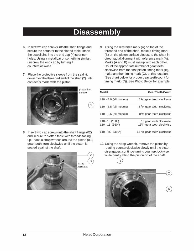
9. Using the reference mark (A) on top of thethreaded end of the shaft, make a timing mark(B) on the piston surface closest to the shaft indirect radial alignment with reference mark (A).Marks (A and B) must line up with each other.Count the appropriate number of gear teethclockwise from the first piston timing mark (B),make another timing mark (C), at this location.(See chart below for proper gear teeth count fortiming mark (C)). See Photo Below for example.
Model Gear Teeth Count
L10 - 3.0 (all models) 6 1/2 gear teeth clockwise
L10 - 5.5 (all models) 6 3/4 gear teeth clockwise
L10 - 9.5 (all models) 81/2 gear teeth clockwise
L10 - 15 (180°) 10 gear teeth clockwiseL10 - 15 (360°) 163/4 gear teeth clockwise
L10 - 25 - (360°) 18 1/2 gear teeth clockwise
10. Using the strap wrench, remove the piston byrotating counterclockwise slowly until the pistondisengages, continue turning counterclockwisewhile gently lifting the piston off of the shaft.
A
B
C
Disassembly
6. Insert two cap screws into the shaft flange andsecure the actuator to the slotted table. Insertthe dowel pins into the end cap (4) spannerholes. Using a metal bar or something similar,unscrew the end cap by turning itcounterclockwise.
7. Place the protective sleeve from the seal kit,down over the threaded end of the shaft (2) untilcontact is made with the piston.
8. Insert two cap screws into the shaft flange (02)and secure to slotted table with threads facingup. Place a strap wrench around the piston (03)gear teeth, turn clockwise until the piston isseated against the shaft.
2
protectivesleeve
strapwrench
2
3
13Helac Corporation
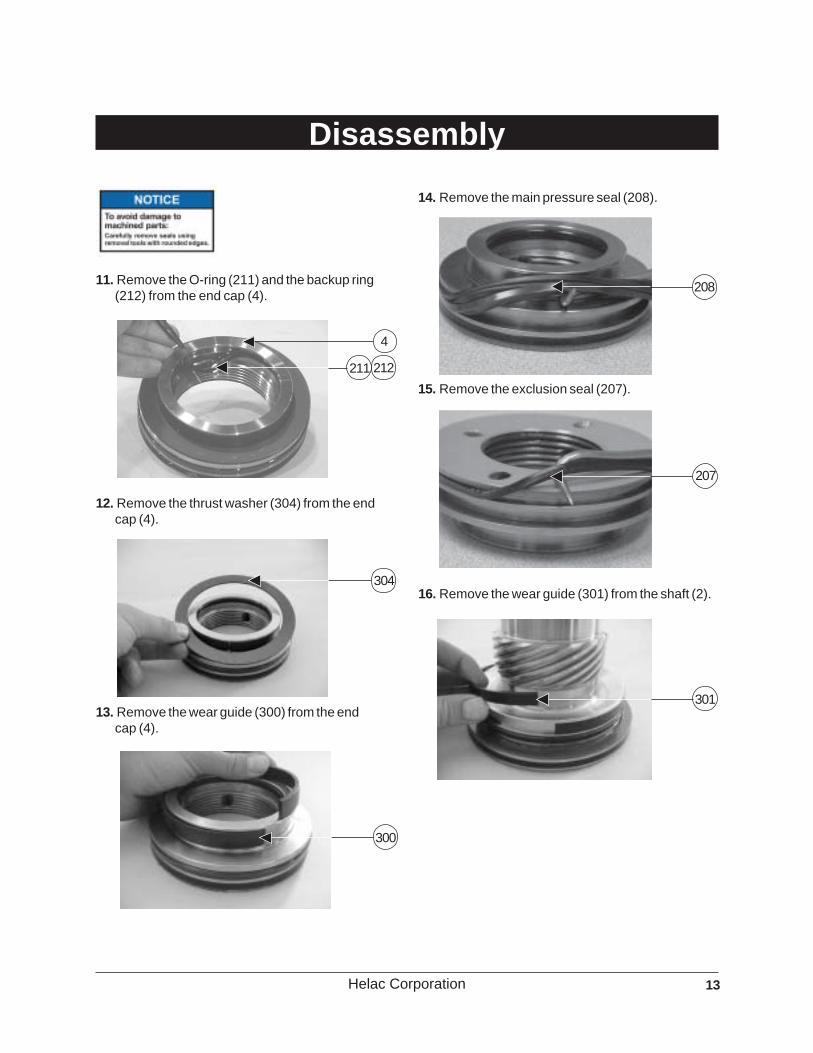
14. Remove the main pressure seal (208).
15. Remove the exclusion seal (207).
11. Remove the O-ring (211) and the backup ring(212) from the end cap (4).
12. Remove the thrust washer (304) from the endcap (4).
Disassembly
304
4
211 212
13. Remove the wear guide (300) from the endcap (4).
300
208
207
16. Remove the wear guide (301) from the shaft (2).
301

14 Helac Corporation
17. Remove the main pressure seal (209).
18. Remove the thrust washer (305).
20. Remove the piston sleeve (3) OD seal (200),
21. Remove the piston sleeve (3) ID seal (202) usinga small pick or seal tool.
19. Remove the exclusion seal (210), from theshaft (02).
210
Disassembly
209
305 202
3
200

15Helac Corporation
Inspection
1. Clean all parts in a wash tank and dry withcompressed air prior to inspecting.
2. Carefully inspect all critical areas for anysurface finish abnormalities: Seal grooves,bearing grooves, thrust surfaces, shaftsurface, housing bore and gear teeth.
Prior to assembly of actuator,these steps must be closelyfollowed to insure proper operationof the actuator.
Small or minor surface scratchescan be carefully polished.

16 Helac Corporation
Seal and Bearing Installation
Lightly oil all seals, seal groovesbearings, and housings prior toinstalling.
Pre-AssemblyAll actuators are timed according to OEMspecifications at Helac's production facility. Thetiming ensures that the actuator will stop at therequired position at the end of the rotation in eitherdirection. Wrong timing can cause the actuator toover rotate resulting in interference and damage ofequipment components. Rotation being too shortcan limit the operating range of the equipment. Theproper gear engagement of shaft, piston andhousing ensures the correct timing. The gear teethare obstructed from view during the assembly of theL10 actuator, so following the manual step by stepis crucial for a successful repair.
Dry RunFor repair personnel not familiar with the L10actuator, it is recommended that a "dry run" withthe following configuration be performed: Install onlythe inner piston seal (202) on page 18 step 10. Theseal will prevent the piston from sliding off of theshaft during installation. Install the thrust washer(305) onto the shaft for proper internal spacing ofcomponents. Proceed to assembly proceduresstarting on page 19, ensure proper fit and timing ofactuator, then disassemble and apply all seals andbearings. For seal and bearing orientation use thecut-away drawing on page 7 as a reference.
Remove the end cap and shaftgrease relief set screws (122) priorto assembly. This will allow excessgrease applied to the thrustwashers to escape duringassembly. Failure to do so mayprevent the end cap and/or shaftfrom fully seating into position.
The set screws are recesseddown deep below the surface ofeach grease relief port, be sure touse the appropriate size hexwrench for these set screws.
1. Using a seal tool (see Page 6) install theexclusion seal (210) onto the shaft.
2. Lightly grease the thrust washer (305) withLithium grease and install onto the shaft (2).
210
305

17Helac Corporation
304
3. Install the main pressure seal (209) onto theshaft (2) using the seal tool.
4. Install the wear guide (301) onto the shaft (2).
5. Install the exclusion seal (207) onto the end cap(4).
6. Install the main pressure seal (208) onto the endcap (4).
7. Install the wear guide (300) onto the end cap (4).
8. Lightly grease the thrust washer (304) withLithium grease and install onto the end cap (4).
Seal and Bearing Installation
301
207
300
208
209

18 Helac Corporation
Seal and Bearing Installation
9. Install the O-ring (211) and backup ring (212)into the inner seal groove on the end cap (4).
10. Install the piston sleeve ID seal (202) into thepiston (3) using a circular motion.
11. Install the piston sleeve OD seal (200) onto thepiston sleeve (3).
200
3
202
212211

19Helac Corporation
Assembly
1. Secure the shaft, flange down to a slotted table,then place the piston (3) onto the threaded endof the shaft (2). Align vertically, the shaftreference mark (A) and the second timing mark(C) on the piston. Press the piston (3) downfirmly over the shaft (2) until the piston ID seal(202) slides over the shaft chamfer (you will feela pop or click) and the piston contacts the shaftgear teeth. Make sure the two marks (A) and (C)are still in line with each other.
2. Place a strap wrench around the piston OD (3)gear teeth, rotate the piston clockwise. Thepiston will engage the shaft (2) gear teeth.Rotate piston until it is firmly seated against theshaft
The shaft (2) reference mark (A)and the first timing mark (B) on thepiston (3) must be lined up. If not,repeat steps 1-2.
3. If applicable, slide the stop tube (400) over theshaft.
The seal inside the stop tube doesnot function as a seal, it's purposeis to keep the stop tube stationaryon the shaft.
4. Place protective sleeve over the shaft (2).
A
B
C
2
3
A
protectivesleeve
2

20 Helac Corporation
Approximate Degree Offset chartbelow for placement of timing mark(F) for each model.
Model Approximate Degree Offset
L10 - 3.0 (180° and 360°) 30° counterclockwise
L10 - 5.5 (180°-185° and 360°) 30° counterclockwise
L10 - 9.5 (185° and 360°) 15° counterclockwise
L10 - 15 (180°) 15°counterclockwiseL10 - 15 (360°) 30°counterclockwise
L10 - 25 (180°) 30° counterclockwise
L10 - 25 (360°) 36° counterclockwise
7. Install two cap screws into the threadedmounting holes on the housing (1). Using aslotted table, secure the housing as shown.
8. Generously apply the appropriate grease to theshaft thrust washer prior to inserting intohousing.
Be sure the end cap and shaftgrease relief set screws (122) areremoved prior to inserting intohousing.
capscrews
slottedtable
5. Make a timing mark (D) on the top lip of thehousing (1), directly in line with the twohydraulic ports (110) on the side with the femalegrease zerk (123).
6. Make a timing mark (E) with a marker, in linewith the female grease zerk (item 123 onassembly drawing page 7) on the shaft flange(2).
Do not use the grease relief port(122) with threaded hole and setscrew for timing procedure.
Using the timing mark (E) or female grease zerk(123) as a reference point, go counterclockwiseby the degrees shown in the chart below, andmake another timing mark (F). Photo belowshows L10-9.5 actuator.
Assembly
F
15°
E
30°
123
D
1
110
123

21Helac Corporation
9. Insert the assembled piston (3) and shaft (2)with protective sleeve applied into the housing(1) (see photo below). The assembly will cometo a stop when the main pressure seal (200)contacts the piston bore in the housing. At thispoint, the outer gear teeth of the piston areclose to coming into engagement with the gearteeth in the housing. Align the two timing marks(D and F) from steps 5 and 6.
10. Install two dowel pins into the shaft flange, placea pry bar between the dowel pins. Gently applypressure to the top of the pry bar. The mainpressure seal (200) will compress and slip intothe housing bore, and the gear teeth betweenthe piston and housing will come in contact. Becareful, the gear teeth may not completely lineup. Using the pry bar rotate the shaft slightlyback and forth while continuously applyinggentle pressure (see photo below). The gearteeth will start to mesh and the shaft/pistonassembly will rotate counterclockwise into thehousing until the shaft flange is almost flush withthe face of the housing. The timing marks D andE should line up.
If timing mark (E) goes past timingmark (D), press and rotate theshaft clockwise, back to timingmark (D).
If the shaft raises (unseats) beforetiming mark (E) lines up withtiming mark (D) going in eitherdirection, the piston has movedfrom it's seated position againstthe shaft and you mustdisassemble and repeat steps9-10.
11. Turn actuator over and place the shaft flangeend down, with threaded bolts inserted, into avise or slotted table. Remove the protectivesleeve from the shaft.
If there is not a slotted tableavailable, place a strap wrencharound the housing to secure it.
12 Coat the threads of the shaft (2) and the endcap (4) with Lithium grease prior to assembly toprevent galling. Thread the end cap onto theshaft until the seal (208) on the end capcontacts the housing (01).
Assembly
F
D
E
D
1
4
208

22 Helac Corporation
14. Visually inspect each locking hole in the endcap (4) for alignment and possible grease and/ordebris. Clean as needed. Place the appropriatesize steel ball (118) (see spec chart below) intoeach locking hole. Using the proper size hexwrench, insert a set screw (106) coated withLoctite 242 locking compound into each lockinghole, securing the end cap to the shaft.
Model Steel Ball Size Specifications
L10 - 3.0 .250 inch (1/4")
L10 - 5.5 .250 inch (1/4")
L10 - 9.5 .312 inch (5/16")
L10 - 15 .312 inch (5/16")
L10 - 25 .312 inch (5/16")
Assembly
If the end cap gets tight and the grind marks(dimples) are not visible, you must use a smallball grinder similar in size to the steel balls (118)and make new grind marks (dimples). Be sureto clean out all of the grinding dust beforecontinuing.
If any portion of the existing grind marks(dimples) are visible when the end cap getstight, loosen or tighten the end cap untilreference mark (A) is lining up.
A
set screwhole
set screwhole
118
lockinghole
106
13. Insert pins into the end cap (4) spanner holes.Using a pry bar, screw the end cap on byturning it in a clockwise direction until itbecomes tight (see General Torque Guidelineschart). Use the reference mark (A) made duringthe disassembly process, as a reference pointto line up the two set screw holes in the end capwith the grind marks (dimples) on the shaftthreads.
During the assembly process atthe factory, there are two smallgrind marks (dimples) made in thethreads of the shaft to lock the endcap and shaft in position. A steelball is placed into each set screwhole on the end cap and locked inposition by the set screw.
Model End Cap - General Torque Guideline
L10 - 3.0 Approximately 40 ft-lbs 54 Nm
L10 - 5.5 Approximately 60 ft-lbs 81 Nm
L10 - 9.5 Approximately 90 ft-lbs 122 Nm
L10 - 15 Approximately 150 ft-lbs 202 Nm
L10 - 25 Approximately 225 ft-lbs 305 Nm
23Helac Corporation
Grease Thrust Washers
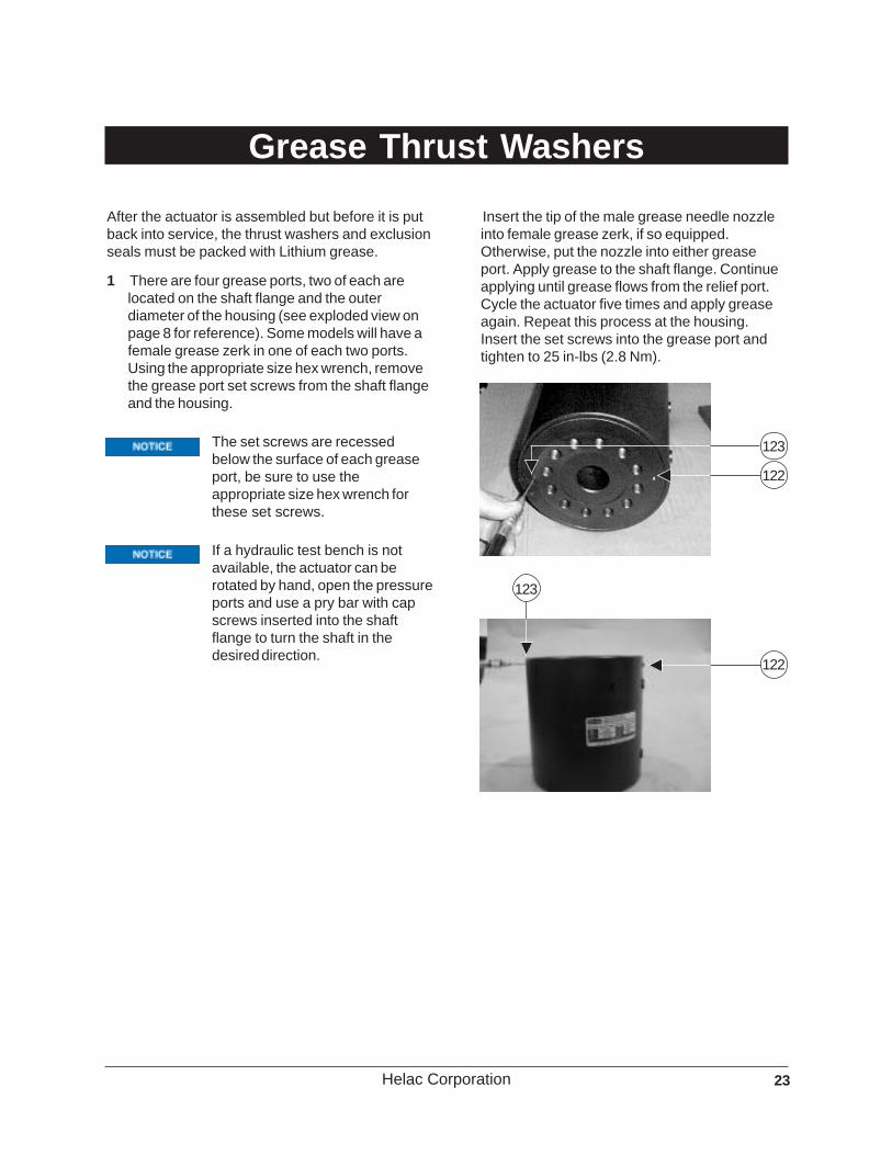
After the actuator is assembled but before it is putback into service, the thrust washers and exclusionseals must be packed with Lithium grease.
1 There are four grease ports, two of each arelocated on the shaft flange and the outerdiameter of the housing (see exploded view onpage 8 for reference). Some models will have afemale grease zerk in one of each two ports.Using the appropriate size hex wrench, removethe grease port set screws from the shaft flangeand the housing.
The set screws are recessedbelow the surface of each greaseport, be sure to use theappropriate size hex wrench forthese set screws.
If a hydraulic test bench is notavailable, the actuator can berotated by hand, open the pressureports and use a pry bar with capscrews inserted into the shaftflange to turn the shaft in thedesired direction.
122
123
123
122
Insert the tip of the male grease needle nozzleinto female grease zerk, if so equipped.Otherwise, put the nozzle into either greaseport. Apply grease to the shaft flange. Continueapplying until grease flows from the relief port.Cycle the actuator five times and apply greaseagain. Repeat this process at the housing.Insert the set screws into the grease port andtighten to 25 in-lbs (2.8 Nm).

24 Helac Corporation
Testing the Actuator
Testing the ActuatorIf the equipment is available, the actuator should betested on a hydraulic test bench. The breakawaypressure—the pressure at which the shaft begins torotate—should be between 100 and 300 psi(7 to 21 bar). Cycle the actuator at least 25 times at3000 psi (210 bar) pressure. At the end of rotation,increase the pressure to 4500 psi(315 bar) to check for leaks and cracks. Performthe test again at the end of the rotation in theopposite direction.
Testing the Actuator forInternal LeakageRotate the shaft to the end of rotation at 3000 psi(210 bar) and maintain pressure. Remove thehydraulic line from the non-pressurized side.Continuous oil flow from the open pressure portindicates internal leakage across the piston.Replace the line and rotate the shaft to the end ofrotation in the opposite direction. Repeat the testprocedure outlined above for the other port.

25Helac Corporation
The OEM has the choice to specify three differentactuator versions for bleeding:
• single bleed screw (photo, page 26)
• single bleed plug (photo, page 27)
• dual bleed screw (photo, page 28)
Bleed screw assemblies can be ordered as anoption. (Helac Part Number S52125)
Actuators with only a single bleed screw or plug willonly bleed one side of the actuator.
Hydraulic systems with a flow rate of 2.0 gallons(7.5 liters) per minute or higher, and short returnlines to tank may easily purge air from the actuator.In this case bleeding is not required.
This procedure is only for actuatorsthat are positioned vertically, withthe shaft flange facing up. All otherpositioned actuators must use theprocedure on page 28.
For best bleeding results, theactuator should be mounted insuch a way as to locate the portsas close to the top as possible.
After installation of the actuator onto the equipment,it is important that all safety devices such as tierods or safety cables are properly reattached.
To purge air from the hydraulic lines, connect them
together to create a closed loop and pump hydraulicfluid through them. Review the OEM's operatingmanual and/or hydraulic schematic to determinewhich hydraulic lines to connect. The length andinside diameter of the hydraulic supply linestogether with pump capacity will determine theamount of pumping time required to fully purge thehydraulic system.
Bleeding will be necessary if excessive backlash isexhibited after the actuator is connected to thehydraulic system. The following steps arerecommended when a minimum of two gallons(8 liters) is purged.
The actuator will either have ableed screw (112) inserted into thebleed plug location, or will have ableed plug set screw (111) that canbe removed and then bled with nobleed screw.
Actuators positioned vertically, with only a singlebleed screw installed:
1. Connect a 3/16" inside diameter, clear vinyl draintube to the bleed screw (112). Secure it with ahose clamp. Place the vinyl tube in a clean 5gallon container to collect the purged oil. The oilcan be returned to the reservoir when theprocedure is complete if needed.
Installation and Bleeding
112

26 Helac Corporation
Hydraulic systems with a flow rate of 2.0 gallons(7.5 liters) per minute or higher, and short returnlines to tank may easily purge air from the actuator.In this case bleeding is not required.
Instructions for bleeding anactuator that is positionedvertically, with the shaft flangefacing up, is on page 27. All otherpositioned actuators use thisprocedure.
After installation of the actuator onto the equipment,it is important that all safety devices such as tierods or safety cables are properly reattached.
To purge air from the hydraulic lines, connect themtogether to create a closed loop and pump hydraulicfluid through them. Review the OEM's operatingmanual and/or hydraulic schematic to determinewhich hydraulic lines to connect. The length andinside diameter of the hydraulic supply linestogether with pump capacity will determine theamount of pumping time required to fully purge thehydraulic system.
Bleeding may be necessary if excessive backlashis exhibited after the actuator is connected to thehydraulic system. The following steps arerecommended when a minimum of two gallons(8 liters) is purged.
2. With an operator at the controls, open the bleedscrew a 1/4 turn. Hydraulically rotate the shaftflange clockwise to the end of rotation andmaintain hydraulic pressure. Oil with small airbubbles will be seen flowing through the tube.
3. Keep the fitting open and rotate the shaft flangein the opposite direction to the end position. Oilwith small air bubbles will be seen flowingthrough the tube.
4. Repeat steps 2 & 3 until at least a 1/2 gallon ofhydraulic fluid is purged and no bubbles can beseen in the oil. Close the bleed screw beforerotating away from the end position.
Actuators positioned vertically, with only a singlebleed plug installed:
5. Using a 1/8" size hex wrench, carefully removethe bleed plug (111), and insert a bleed screw(112).
Repeat steps 1 through 4.
Installation and Bleeding
111
hexwrench
27Helac Corporation
Installation and Bleeding
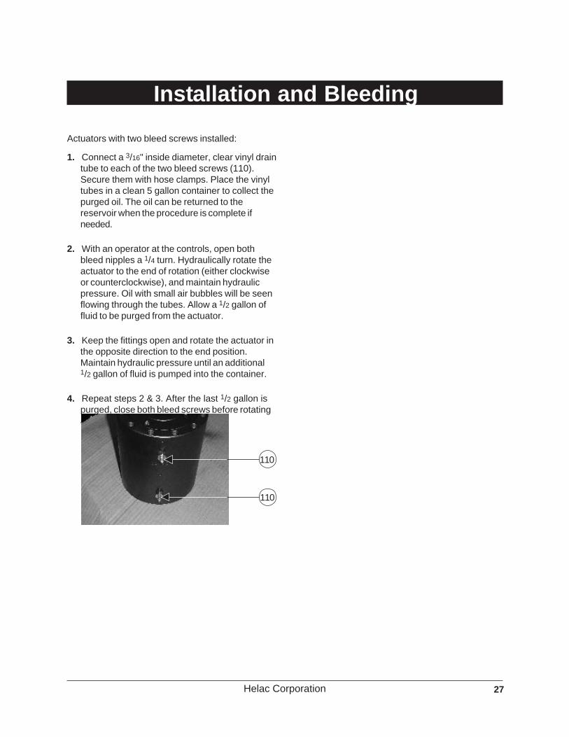
Actuators with two bleed screws installed:
1. Connect a 3/16" inside diameter, clear vinyl draintube to each of the two bleed screws (110).Secure them with hose clamps. Place the vinyltubes in a clean 5 gallon container to collect thepurged oil. The oil can be returned to thereservoir when the procedure is complete ifneeded.
2. With an operator at the controls, open bothbleed nipples a 1/4 turn. Hydraulically rotate theactuator to the end of rotation (either clockwiseor counterclockwise), and maintain hydraulicpressure. Oil with small air bubbles will be seenflowing through the tubes. Allow a 1/2 gallon offluid to be purged from the actuator.
3. Keep the fittings open and rotate the actuator inthe opposite direction to the end position.Maintain hydraulic pressure until an additional1/2 gallon of fluid is pumped into the container.
4. Repeat steps 2 & 3. After the last 1/2 gallon ispurged, close both bleed screws before rotatingaway from the end position.
110
110

28 Helac Corporation
Troubleshooting Guide
PROBLEM SEE CAUSES AND SOLUTIONS BELOWShaft rotates slowly or not at all 1-6
Operation is erratic or not responsive 7
Shaft will not fully rotate 8
Selected position cannot be maintained 3,4,7
CAUSE SOLUTION1. Insufficient torque output Verify correct operating pressure. Do not exceed OEM's
pressure specifications. Load may be above maximumcapacity of the actuator.
2. Low rate of fluid flow Inspect ports for obstructions and hydraulic lines forrestrictions and leaks.
3. Control or Counterbalance valve has Disconnect hydraulic lines and bypass valve. Leave valveinternal leak ports open and operate the actuator through housing ports
(do not exceed OEM's operating pressure).The valve must be replaced if a steady flow of fluid isseen coming from the valve ports.
4. Piston and/or shaft seal leak Remove the plug and the housing's valve ports. Operatethe actuator through the housing ports. Conduct theinternal leakage test as described in the Testing Sectionon page 24 of this manual.
5. Corrosion build-up on the thrust surfaces Re-build the actuator. Remove all rust and then polish.*6. Swollen seals and composite bearings Re-build the actuator. Use fluid that is compatible
caused by incompatible hydraulic fluid with seals and bearings. Contact Helac for moreinformation.
7. Air in actuator Purge air from actuator. See bleeding procedure startingon page 25.
8. Port fittings are obstructing the piston Check thread length of port fittings. Fittings shouldduring stroke not reach inside the housing bore.
9. Twisted or chipped gear teeth. Overload conditions. Check for binding. Actuator may ormay not be able to be rebuilt and may need to bereplaced.
* Replacement part may be needed.

29Helac Corporation
Hydraulic Rotary Actuator Product Warranty
Standard Warranty Information
Helac Corporation warrants its manufactured products to be free from defective material and factory workmanship.Helac Corporation shall replace or repair such products, which under normal use and service disclose suchdefects, and return the repaired or replacement products to the purchaser prepaid. Claims under this warranty willbe satisfied only by repair or replacement of the unit or any defective part thereof. No cash payment or credit will bemade for defective materials, workmanship, labor or incidental charges. Products under warranty shall be returnedto Helac Corporation’s manufacturing facility at 225 Battersby Avenue, Enumclaw, Washington 98022 USA,transportation prepaid by the purchaser, for inspection by Helac Corporation, whose opinion as to defects shall beconclusive.
The warranty period shall be 12 months from the date of shipment from Helac Corporation’s manufacturing facilityfor Helac Corporation approved applications. This warranty shall be voided as to any products which have beenrepaired, worked upon, or altered by persons not authorized by Helac Corporation, or which have been subject tomisuse, negligence, accident, or overload. In no event shall Helac Corporation be liable for any incidental orconsequential damages.
Helac Corporation reserves the right to make changes in the design or construction of any of its products at anytime without incurring any obligations to make changes or alterations to products previously sold.
This warranty is in lieu of all other and/or prior warranties, expressed or implied, and no other company or personis authorized to represent or assume for Helac Corporation any liability in connection with the sale of HelacCorporation products other than set forth herein.
Return and Debit Policy for Actuators
Unless agreed to in advance, all actuators will be shipped to Helac Corporation, freight prepaid within seven daysafter receipt of return authorization. Prior to any returns, a Return Material Authorization (RMA) form is to berequested from an authorized Helac Corporation representative. Upon receipt of the RMA form, the customer is toprovide when applicable, the part number, serial number, failure date, description of problem and the customerclaim or reference number. All shipments to Helac Corporation are to include the completed RMA form.
Upon receipt of the actuator(s) at the Helac Corporation facilities, an inspection will be performed and anauthorized representative will provide a written quote. This quote will list the findings of the inspection and will statewhether or not the warranty claim has been accepted. Actuators returned for credit may be subject to the HelacCorporation re-stocking fee.
If Helac Corporation does not receive a response to their quote within 30 calendar days, the actuator will be eitherscrapped or returned and an invoice for the debit amount, including the freight charges, will be sent to the claimoriginator.
Return and Debit Policy for Service Parts
Return of service parts, normally stocked by Helac Corporation, must be authorized in advance. This will includeseal and bearing kits as well as any and all fabricated parts. Return of any special order parts will be authorized ona case-by-case basis. All returns are to be shipped to Helac Corporation freight prepaid within seven days afterreceipt of return authorization. Helac Corporation has a minimum re-stocking fee of 20 percent.
Prior to any returns, Return Material Authorization (RMA) form is to be requested from an authorized HelacCorporation representative. Upon receipt of the RMA form, the customer is to provide part number, receipt date,description of problem and the customer claim number. All shipments to Helac Corporation are to include thecompleted RMA form.

30 Helac Corporation
Notes

31Helac Corporation
Notes

HELAC CORPORATION225 BATTERSBY AVENUE • ENUMCLAW, WA 98022 USAPHONE 360.825.1601 • FAX 360.825.1603 • www.helac.com
®
Rev
02-
2005
About Helac Corporation
As a leader in the fluid power industry for over30 years, Helac Corporation manufactures acomprehensive line of hydraulic rotaryactuators used as component parts for OEMsand aftermarket attachments for theconstruction equipment industry. Helac rotaryactuators are best known for their tremendoustorque output, compact dimensions,
exceptional load bearing capability and rugged,reliable performance. Helac PowerTilt andPowerGrip, two specialty products, increasethe utilization of backhoes and excavators.Over 1,000 worldwide customers in diversemarkets depend on Helac's product line toprovide product quality, reliability, ease of useand durability.