service and installation manual
TRANSCRIPT
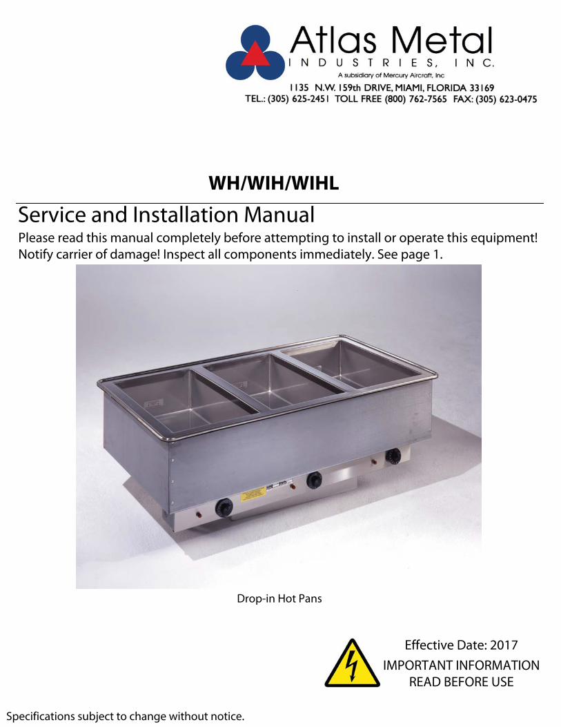
WH/WIH/WIHL
Service and Installation ManualPlease read this manual completely before attempting to install or operate this equipment! Notify carrier of damage! Inspect all components immediately. See page 1.
Drop-in Hot Pans
Effective Date: 2017IMPORTANT INFORMATION
READ BEFORE USE
Specifications subject to change without notice.
CONTENTS
RECEIVING AND INSPECTING THE EQUIPMENT1. VISUALLY INSPECT THE SHIPPING CRATE. DAMAGE SHOULD BE NOTED AND REPORTED TO THE DELIVERING CARRIER.
6. SAVE ALL CRATING MATERIALS UNTIL INSPECTION HAS BEEN MADE OR WAIVED.
5. FREIGHT CARRIERS CAN SUPPLY THE NECESSARY FORMS ON REQUEST.
4. REQUEST AN INSPECTION BY THE SHIPPING COMPANY FOR THE DAMAGED EQUIPMENT WITHIN 10 DAYS FROM RECEIPT OF THEEQUIPMENT
3. IF CRATE IS NOT DAMAGED AND THERE IS CONCEALED DAMAGE TO THE EQUIPMENT, NOTIFY THE CARRIER. NOTIFICATION MUST BEMADE VERBALLY AND IN WRITING.
2. IF DAMAGED, OPEN AND INSPECT CONTENTS WITH CARRIER.
SERIAL NUMBER LOCATION
INSTALLATION DATE: _____________________________________________
MODEL #:_______________________________________________________
SERIAL #: _______________________________________________________
THE SERIAL AND MODEL# CAN BE FOUND ON THE OPERATORS CONTROL PANEL. WHEN CALLING ATLAS FOR PARTS AND SERVICE ALWAYS HAVE THIS INFORMATION AVAILABLE.
RECEIVING & INSPECTING EQUIPMENT....................................................................................................................................................................................1
SERIAL AND MODEL NUMBER LOCATION...............................................................................................................................................................................1
WH SPECIFICATIONS, FEATURES AND ACCESSORIES.....................................................................................................................................................2-3
INSTALLATION, OPERATION AND S/S MAINTENANCE........................................................................................................................................................8ELECTRICAL CHARACTERISTICS AND CUT-OUT REQUIREMEMENTS..............................................................................................................................8REMOTE CONTROL INSTALLATION............................................................................................................................................................................................9
PARTS LIST........................................................................................................................................................................................................................................10
AUTOMATIC WATER FILL INSTALLATION, OPERATION & PARTS DIAGRAM..............................................................................................................11
TROUBLE SHOOTING GUIDE.......................................................................................................................................................................................................12
ELECTRICAL SCHEMATICS............................................................................................................................................................................................................13
LIMITED WARRANTY......................................................................................................................................................................................................................14
WARRANTY INFORMATION.........................................................................................................................................................................................................15
WIH SPECIFICATIONS, FEATURES AND ACCESSORIES.....................................................................................................................................................4-5
WIHL SPECIFICATIONS, FEATURES AND ACCESSORIES...................................................................................................................................................6-7

Project: ___________
Item No.: ___________
Quantity: ___________
DROP-IN SERVING EQUIPMENT
HOT PAN
Electrically Heated
Single Control
WH-2
WH-3
WH-4
WH-5
WH-6WH-3
TOP: Constructed of 18 gauge, type 304 stainless steel, die
stamped flange with a raised perimeter bead. There shall be
a solid vinyl gasket under the beaded edge to form a seal to
the counter top, thus preventing seepage or marring of the
counter top. Embossed mounting lugs are provided along the
inner surface of the top to hold the removable separator
channels in place.
LINER: The inner liner shall be 18 gauge, type 304 stainless
steel, one piece construction, all welded ground and polished
to a uniform finish. All corners are coved with a minimum 1/4"
radius. A 3/4" dia. drain, with strainer, brass nipple, and valve
is provided.
INSULATION: The pan is fully insulated with high density
fiberglass insulation, 1" thick on all sides, 2" thick on the bot-
tom and enclosed by a 22 gauge galvanized steel outer case.
ELECTRICAL: The unit is provided with individual 850 watt
heating elements, pre-wired to a single thermostat control
with a pilot light. A 6’ long, 3-wire cord and plug is provided,
extending from the control box located under the unit, on
operator's left. Bottom of outer case can be removed for ac-
cess to electrical components. Available for single phase
power only.
Specifications subject to change without notice.
SPECIFICATIONS STANDARD FEATURES� Fully insulated to retain heat - protects fixtures and
saves energy
� Open Bain Marie construction
� Thermostatically controlled
� Factory applied gasket - makes installation a snap and
seals units to the counter top, thus eliminating seepage
� Accommodates standard 12” X 20” pans with the use
of separator channel(s), or fractional size pans with
the use of optional adapter bars
� Wet operation only
� 1-Year Parts & Labor Warranty
� UL Listed, ETL Listed
ACCESSORIES� Stainless steel adapter bars (pgs. DI-51-52)
� Stainless steel adapter plates (pgs. DI-51-52)
� CP - Cover Plate with handles, S/S
� RDVE - Rear Drain Valve Extension (1) required
� RT-1 - Remote Thermostat for counter installation, 24”
long
� RTL-1 - Remote Thermostat for counter installation,
50” long
� MS - Master on/off switch
� AF - Automatic water fill
DI-1*Please see Operation & Installation Manual for ALL operation and maintenance details.

A
24”
12”
12”
PLAN VIEW REMOVABLE SEPARATOR
CHANNEL
9”
4-1/8” 7-1/4”ELEVATION
19-7/8” ID
6” ID
2-5/8”3-3/4”
2-1/2” 3-3/4”
MODEL WATTAGE VOLTAGE/KW/AMPSNEMA
# PLUG
WH-2 850WATT
120V - 1.7KW - 14.2
208V - 1.7KW - 8.2
240V - 1.7KW - 7.1
5-20P
6-15P
6-15P
1000WATT120V - 2.0KW 16.7
208V - 2.0KW - 9.6
240V - 2.0KW - 8.3
5-30P
6-15P
6-15P
WH-3 850WATT120V - 2.55KW - 21.3
208V - 2.55KW - 12.3
240V - 2.55KW - 10.6
5-30P
L6-20P
6-15P
1000WATT120V - 3.0KW - 25.0
208V - 3.0KW - 14.4
240V - 3.0KW - 12.5
5-50P
L6-20P
L6-20P
WH-4 850WATT 208V - 3.4KW - 16.4
240V - 3.4KW - 14.2
L6-30P
L6-20P
1000WATT 208V - 4.0KW - 19.2
240V - 4.0KW - 16.7
L6-30P
L6-30P
WH-5 850WATT 208V - 4.25KW - 20.4
240V - 4.25KW - 17.7
L6-30P
L6-30P
1000WATT 208V - 5.0KW - 24.0
240V - 5.0KW - 20.8
L6-30P
L6-30P
WH-6 850WATT 208V - 5.1KW - 24.5
240V - 5.1KW - 21.3
6-50P
L6-30P
1000WATT 208V - 6.0KW - 28.8
240V - 6.0KW - 25.0
6-50P
6-50P
MODEL “A” PAN SIZE
COUNTER
CUT-OUT
(REQUIRED)
W X L
SHIP WT.
(LBS.)
WH-2 29-3/4”
(75.5cm)19-7/8” X 25-1/2” X 6”
(50.4 X 64.7 X 15.2cm)22-1/4” X 28”
(56.5 X 71.1cm)116
(52.6kg)
WH-3 43-1/2”
(110.4cm)19-7/8” X 39-1/4” X 6”
(50.4 X 99.6 X 15.2cm)22-1/4” X 41-3/4”
(56.5 X 106cm)148
(67.1kg)
WH-4 57-1/4”
(145.4cm)19-7/8” X 53” X 6”
(50.4 X 134.6 X 15.2cm)22-1/4” X 55-1/2”
(56.5 X 140cm)174
(78.9kg)
WH-5 71”
(180.3cm)19-7/8” X 66-3/4” X 6”
(50.4 X 169.5 X 15.2cm)22-1/4” X 69-1/4”
(56.5 X 175.8cm)210
(95.3kg)
WH-6 84-3/4”
(215.2cm)19-7/8” X 80-1/2” X 6”
(50.4 X 204.4 X 15.2cm) 22-1/4” X 83”
(56.5 X 210.8cm)227
(102.9kg)
Atlas Metal Industries 1135 NW 159th Dr. Miami, FL 33169 (800) 762-7565 Fax: (305) 623-0475 atlasfoodserv.com
3/17-sc
Note: Numeral following the model letters denotes the 12X20 pan capacity
DI-2
Electrical Characteristics
END VIEW

Project: ___________
Item No.: ___________
Quantity: ___________
DROP-IN SERVING EQUIPMENT
HOT PAN
Electrically Heated
Individual Controls
WIH-1
WIH-2
WIH-3
WIH-4
WIH-5
WIH-6
TOP: Constructed of 18 gauge, type 304 stainless steel, die
stamped with a raised perimeter bead. There shall be a solid
vinyl gasket under the beaded edge to form a seal to the
counter top, thus preventing seepage or marring of the
counter top.
HOT FOOD WELLS: Individual hot food wells shall be 18
gauge, type 304 stainless steel, one piece construction, all
welded, ground and polished to a uniform finish. All corners
are coved with a minimum 1/4" radius. Each well is provided
with an 850 watt heating element (1000 watt on the WIH-1).
INSULATION: The pan is fully insulated with high density
fiberglass, 1" thick on all sides, 2" thick on the bottom and en-
closed with a 22 gauge galvanized steel outer case.
ELECTRICAL: The unit is provided with an individual
thermostat control with a pilot light for each well. All heating
elements and controls are pre-wired, and a 6' long, 3-wire
cord and plug is provided, extending from the control box
located under the unit, on operator's left. Bottom of outer
case can be removed for access to electrical components.
Specifications subject to change without notice.
SPECIFICATIONS STANDARD FEATURES� Fully insulated to retain heat - protects fixtures and
saves energy
� Individual thermostat controls - the operator can
control the temperature of each well separately
� Factory applied gasket - makes installation a snap
and seals units to the counter, thus eliminating
seepage
� Accommodates standard 12”x20” pans, or fractional
size pans with the use of optional adapter bars
� Wet operation only
� 1-Year Parts & Labor Warranty
� UL Listed, ETL Listed
ACCESSORIES� Stainless steel adapter bars (pg DI-51-52)� Stainless steel adapter plates (pg DI-51-52) � CP - Cover Plate with handles, S/S� D - Individual Drain and Valve for each well (3/4” dia.
drain)
� DM - Individual Drain for each well with manifold to
single valve� DMV - Individual Drain with valve for each well with
manifold to single valve� DME - Individual drain for each well with manifold to
single valve w/ rear extension� RDVE - Rear Extension for D, DM, & DMV (1)
required� RT - Remote Thermostats for counter installation, 24”
long
� RTL - Remote Thermostats for counter installation, 50”
long
� MS - Master on/off switch
� AF - Automatic water fill (NOTE: DM required for water
fill)
WIH-3
DI-3*Please see Operation & Installation Manual for ALL operation and maintenance details.

Atlas Metal Industries 1135 NW 159th Dr. Miami, FL 33169 (800) 762-7565 Fax: (305) 623-0475 atlasfoodserv.com
3/17-sc
Note: Numeral following the model letters denotes the 12X20 pan capacity
DI-4
Electrical Characteristics
A
24”
PLAN VIEW
9”
3-3/4”
2-1/8”
ELEVATION
19-7/8” ID
7-1/2”
6” ID
5-1/4”
END VIEW
MODEL WATTAGE VOLTAGE/KW/AMPS NEMA #PLUG
WIH-1 1000WATT120V - 1.0KW -8.3
208V - 1.0KW - 4.8
240V - 1.0KW - 4.2
5-15P
6-15P
6-15P
WIH-2 850WATT120V - 1.7KW - 14.2
208V - 1.7KW - 8.2
240V - 1.7KW - 7.1
5-20P
6-15P
6-15P
1000WATT120V - 2.0KW - 16.7
208V - 2.0KW - 9.6
240V - 2.0KW - 8.3
L5-30P
6-15P
6-15P
WIH-3 850WATT120V - 2.55KW - 21.3
208V - 2.55KW - 12.3
240V - 2.55KW - 10.6
L5-30P
L6-20P
6-15P
1000WATT120V - 3.0KW - 25.0
208V - 3.0KW - 14.4
240V - 3.0KW -12-5
5-50P
L6-20P
L6-20P
WIH-4 850WATT208V - 3.4KW - 16.4
240V - 3.4KW - 14.2
L6-30P
L6-20P
1000WATT208V - 4.0KW - 19.2
240V - 4.0KW - 16.7
L6-30P
L6-30P
WIH-5 850WATT208V - 4.25KW - 20.4
240V - 4.25KW - 17.7
L6-30P
L6-30P
1000WATT208V - 5.0KW - 24.0
240V - 5.0KW - 20.8
L6-30P
L6-30P
WIH-6 850WATT208V - 5.1KW - 24.5
240V - 5.1KW - 21.3
6-50P
L6-30P
1000WATT208V - 6.0KW - 28.8
240V - 6.0KW - 25.0
6-50P
6-50P
MODEL “A”
COUNTER
CUT-OUT
(REQUIRED)
W X L
CONTROL
PANEL
CUT-OUT
(IF REQUIRED)
SHIP WT.
(LBS.)
WIH-1 16”
(40.6cm)22-1/4” X 14-1/4”
(56.5 X 36.8cm)4-1/2” X 6-1/4”
(11.4 X 15.8cm)41
(18.5kg)WIH-2 29-3/4”
(75.5cm)22-1/4” X 28”
(56.5 X 71.1cm)4-1/2” X 12-1/4”
(11.4 x 31.1cm)112
(50.8kg)WIH-3 43-1/2”
(110.4cm)22-1/4” X 41-3/4”
(56.5 X 111.1cm)4-1/2” X 26”
(11.4 X 66cm)152
(68.9kg)WIH-4 57-1/4”
(145.4cm)22-1/4” X 55-1/2”
(56.5 X 140.9cm)4-1/2’ X 39-3/4”
(11.4 X 100.9cm)188
(85.3kg)WIH-5 71”
(180.3cm)22-1/4” X 69-1/4”
(56.5 X 175.8cm)4-1/2” X 53-1/2”
(11.4 X 135.8cm)225
(102kg)WIH-6 84-3/4”
(213.3cm)22-1/4” X 83”
(56.5 X 210.8cm)4-1/2” X 67-1/4”
(11.4 X 170.8cm)268
(121.5kg)
SHOWN WITH OPTIONAL DME -DRAIN AND MANIFOLD WITHREAR EXTENSION

Project: ___________
Item No.: ___________
Quantity: ___________
SLIM-LINE DROP-IN SERVING EQUIPMENT
SLIM-LINE
HOT PAN
Electrically Heated
Individual Controls
WIHL-2
WIHL-3
WIHL-4
TOP: Constructed of 18 gauge, type 304 stainless steel, die
stamped with a raised perimeter bead. There shall be a solid
vinyl gasket under the beaded edge to form a seal to the
counter top, thus preventing seepage or marring of the
counter top.
HOT FOOD WELLS: Individual hot food wells shall be 18
gauge, type 304 stainless steel, one piece construction, all
welded, ground and polished to a uniform finish. All corners
are coved with a minimum 1/4" radius. Each well is provided
with an 850 watt heating element.
INSULATION: The pan is fully insulated with high density
fiberglass insulation, 1" thick on all sides, 2" thick on the
bottom, and enclosed by a 22 gauge galvanized steel outer
case.
ELECTRICAL: The unit is provided with an individual
thermostat control and pilot light for each well. All heating
elements and controls are pre-wired, and a 6' long, 3-wire
cord and plug is provided, extending from the control box
located under the unit, on operator's left. Bottom of outer
case can be removed for access to electrical components.
Specifications subject to change without notice.
SPECIFICATIONS STANDARD FEATURES� Slim line configuration - it can install in counters only
16” wide
� Fully insulated to retain heat - protects fixtures
and saves energy
� Individual thermostat controls - the operator can
control the temperature of each well separately
� Factory applied gasket - makes installation a snap and
seals units to the counter top, thus eliminating
seepage
� Accommodates standard 12” X 20” pans, or fractional
size pans with the use of optional adapter bars.
� Wet operation only
� 1-Year Parts & Labor Warranty
� UL Listed, ETL Listed
ACCESSORIES� Stainless steel adapter bars (pg DI-51-52)� Stainless steel adapter plates (pg DI-51-52) � CPL - Cover Plate with handles, S/S� D - Individual Drain and Valve for each well (3/4” dia.
drain)
� DM - Individual Drain for each well with manifold to
single valve� DMV - Individual Drain with valve for each well with
manifold to single valve� DME - Individual drain for each well with manifold to single valve w/ rear extension� RDVE - Rear Extension for D, DM, DMV & DME (1)
required� RT - Remote Thermostats for counter installation, 24”
long
� RTL - Remote Thermostats for counter installation, 50”
long
� MS - Master on/off switch
� AF - Automatic water fill (NOTE: DM required for water
fill)
WIHL-2
DI-5*Please see Operation & Installation Manual for ALL operation and maintenance details.

Atlas Metal Industries 1135 NW 159th Dr. Miami, FL 33169 (800) 762-7565 Fax: (305) 623-0475 atlasfoodserv.com
3/17-scDI-6
Electrical Characteristics
A
16”
PLAN VIEW
9”
3-3/4”
10-1/4”
ELEVATION
11-7/8” ID
6”
2-1/2”3-3/4”
END VIEW
MODEL “A”
COUNTER
CUT-OUT
(REQUIRED)
W X L
CONTROL
PANEL
CUT-OUT
(IF REQUIRED)
SHIP
WT.
(LBS.)
WIHL-246”
(116.8cm)14-1/4” X 44-1/4”
(36.8 X 113.6cm)4-1/2” X 12-1/4”
(11.4 X 31.1cm)118
(53.5kg)
WIHL-367-3/4”
(172cm)14-1/4” X 66”
(36.8 X 167.6cm)4-1/2” X 26”
(11.4 X 66cm)176
(79.8kg)
WIHL-489-1/2”
(227.3cm)14-1/4” X 87-3/4”
(36.8 X 222.8cm)4-1/2” 39-3/4”
(11.4 X 100.9cm)210
(95.2kg)
MODEL WATTAGE VOLTAGE/KW/AMPSNEMA
# PLUG
WIHL-2 850WATT120V - 1.7KW - 14.2
208V - 1.7KW - 8.2
240V - 1.7 KW - 7.1
5-20P
6-15P
6-15P
1000WATT120V - 2.0KW - 16.7
208V - 2.0KW - 9.6
240V - 2.0KW - 8.3
5-30P
6-15P
6-15P
WIHL-3 850WATT120V - 2.55KW - 21.3
208V - 2.55KW - 12.3
240V - 2.55KW - 10.6
5-30P
L6-20P
6-15P
1000WATT120V - 3.0KW - 25.0
208V - 3.0KW - 14.4
240V - 3.0KW - 12.5
5-50P
L6-20P
L6-20P
WIHL-4 850WATT208V - 3.4KW - 16.4
240V - 3.4KW - 14.2
L6-30P
L6-20P
1000WATT208V - 4.0KW - 19.2
240V - 4.0KW - 16.7
L6-30P
L6-30P
Note: Numeral following the model letters denotes the 12X20 pan capacity

WH/WIH/WIHL ----------------------------------------------------------------------------------------------------------------------------------------------------------
INSTALLATION Provide the correct counter cut-out opening and drop in. The vinyl gasket assures complete seating. A non-toxic silicone seal may be used between the gasket and counter top (not required). The unit is supplied with a power cord and NEMA plug. Refer to the data plate on the control panel for the amperage and voltage information. Use a licensed electrician when installing power source.
* Control box on 14 1/4" side.---------------------------------------------------------------------------------------------------------------------------------------------------------
OPERATION
During operation the unit must be used with water and the thermostat must be set at position #10. The thermostat dial has an off position and is numbered 1 to 10 (Number 10 is the highest and mandatory setting for operation).
-------------------------------------------------------------------------------------------------------------------------------- MAINTENANCE
NEVER CLEAN PANS WITH A CHLORIDE BASED PRODUCT. CHLORIDES OR IMPROPER CLEANING COULD SCAR, MARK AND/OR CORRODE PANS. DO NOT USE STEEL WOOL OR ABRASIVE PRODUCTS.TO CLEAN USE SOAPY WARM WATER, RINSE THOROUGHLY TO REMOVE ALL RESIDUES. FAILURE TO MEET THESE CONDITIONS WILL VOID WARRANTY. --------------------------------------------------------------------------------------------------------------------------------

Subsidiary of Mercury Aircraft, Inc.
1135 N.W. 159th DR., MIAMI, FL 33169PHONE (305) 625-2451, (800) 762-7565, FAX (305) 623-0475, E-mail: [email protected]
WIH-REMOTE INSTALLATION
414"31
4"
FRONT FACE
DIAL
138"
NUTS
SCREW
PANEL WITH CUT-OUT
STUDS
318"
GALVANIZED BOX
534"
INSTALLATION OF THE REMOTE CONTROL HOT UNITS .---------------------------------------------------------------------------------------------------------------------------------------Provide the correct Cut-Out opening for the remote control panel (see chart below). Remove control box from the bottom of the unit.
1) Remove black control dial from front of control panel by loosening screws. 2) Remove 6/32 fiber nuts from the back of the control box. 3) Mount the S/S front plate to the Cut-Out in apron. 4) Attach the galvanized box to the S/S front plate.
The unit is ready to be connected to the electrical receptacle. Refer to the data plate on the control panel for the amperage and voltage information. Use a licensed electrician when installing power source.
MODEL CUT-OUT SIZE1 4 1/2 x 6 1/42 4 1/2 x 12 1/43 4 1/2 x 264 4 1/2 x 39 3/45 4 1/2 x 53 1/26 4 1/2 x 67 1/4
CAUTION: HANDLE CONTROL PANEL & CONDUIT CAREFULLY,THERMOSTAT CAPILLARY TUBE IS VERY FRAGILE, IF BROKEN, HEATING SYSTEM WILL NOT OPERATE. FAILURE TO MEET THESE CONDITIONS WILL VOID WARRANTY.
WH/WIH STANDARD INSTALLATION

Subsidiary of Mercury Aircraft, Inc.
1135 N.W. 159th DR., MIAMI, FL 33169
PHONE (305) 625-2451, (800) 762-7565, FAX (305) 623-0475, E-mail: [email protected]
PARTS LIST ELECTRICAL HEATED UNITS W/AUTOMATIC WATER FILL
WH/ WIHD&M/ WIHLD&M- /WIHD&M- 1-6 SERIES
3
4
24
44
43
37
45
39
38
40
41
42
36
34
35
33
31
32
1
2
46
ITEM NUMBER
PART NUMBER DESCRIPTION
1 7002-0+Model # Vinyl Bead Gasket 2 86-3202 Perforated Snap in Drain 3 1097 Dial 4 1099 Pilot Light 5 3007-3 3/4" Brass Nipple 7” long 6 3016-1 Brass Gate Valve 7 1088 P-136 Terminal (#22 & 18 wire) 8 1089 P-151 Terminal (#10 & 12 wire) 9 1090 P-144 Terminal (#14 & 16 wire)
10 1098 S Screw Thermostat Mounting 11 2500 Remote Thermostat with 48" Bulb 12 2500-5 Remote Thermostat with 72" Bulb 13 1012-3 12" Nickel Wire 14 1014-4 14" Nickel Wire 15 1096 Thermostat 16 S81113-2 Element Holder 17 SC0099-238 S/S Element Holder 18 1053 120V-850W Element 19 1054 208V-850W Element 20 1055 240V-850W Element 21 1056 120V-1000W Element 22 1057 240V-1000W Element 23 1058 208V-1000W Element
24 1002 Power Cord 14/3 1004 Power Cord 12/3
1004-4 Power Cord 10/3
ITEM NUMBER
PART NUMBER DESCRIPTION
25 12-228 Plug 20Amp 240V 26 1022 Plug 30Amp 240V 27 12-256 Plug 30Amp 120V 28 1014-7 #12 Green Wire (Ground) 29 1014-8 #14 Green Wire (Ground) 30 1001-1 50 Amp Cord & Plug 31 48-22 S/S 10 x 1/2 Screws 32 S84553 Reservoir Assembly 33 51-25 1/4" x 3/8" NPT Male Conn. 34 2050 Brass Flare Nut 35 2031 1/4" Copper Tubing 36 21-23 1/4" x 1/4" Brass Union
37 600022 Dual check vacuum breaker
#98d NPTM 1/4” (BACK FLOW PREVENTION)
38 30-46 90º Street Elbow
39 1800-3904 Solenoid Valve 120V 1800-3903 Solenoid Valve 240V
40 600002 Brass In Line Strainer 41 1800-35 Ball In Valve 42 1800-39 Close Nipple
43 87-69 90º 1/2" to 1/4 Reducing Elbow Brass
44 87-70 1/2 dia. Brass Pipe Threaded Both Ends
45 87-68 1/8” Male to 1/4” female reducer
46 1069-1 Switch

AUTOMATIC WATER FILL UNITS
WIH, WH AND WCMHP/RMHP SERIESINSTALLATION
When installing water supply to the unit, the supply lines must be purged to remove particles from damaging the solenoid valve operation. A factory supplied in-line water strainer is installed. However, it is recommended the customer supply a primary water filtering system for protection.
*Note-Atlas Metal Ind. Inc. is not responsible for routine maintenance of the strainer or customersupplied water filter system.
*Atlas Metal Industries Inc. recommends that all units installed to a water source use our Autofillor any backflow protection of your choice. Please refer to your local code.
Any attempt to change or modify the Auto Fill system will void the warranty.
OPERATIONTo operate the Auto Fill system, turn the Auto-fill On/Off switch, located on the control panel, to the On position. Allow water to complete filling the pan to the water level mark before energizing the heating cycle.
*Note - Factory water depth settings for A/F units are 1/4" for WIH, 1/2" for WH & WCMHP/RMHP are 1/2"above the heating element cover.DO NOT manually add water to Auto-fill units above water level mark, damage and leakage to theAutomatic sensor could result. As the water evaporates the pans will fill automatically. It isrecommended that the Auto Fill be in the off position when not in use.

Subsidiary of Mercury Aircraft, Inc.
1135 N.W. 159th DR., MIAMI, FL 33169
PHONE (305) 625-2451, (800) 762-7565, FAX (305) 623-0475, E-mail: [email protected]
Electric Hot Food Drop-In Trouble Shooting Guide Symptom Probable Cause
Unit not plugged in. No power at receptacle. Thermostat and or switch not in the on position.
Unit will not heat
Call factory for service at 1-800-762-7565 Thermostat’s not turned to the highest setting. Food products not hot enough when placed in unit. Food product not being stirred or rotated. Heat lamp or head strip over the food product is recommended.
Food products not hot enough.
Call factory for service at 1-800-762-7565.
NOTE: Before starting any warranty repair work you must first call the factory for authorization.
Failure to do so can make you responsible for repair cost.
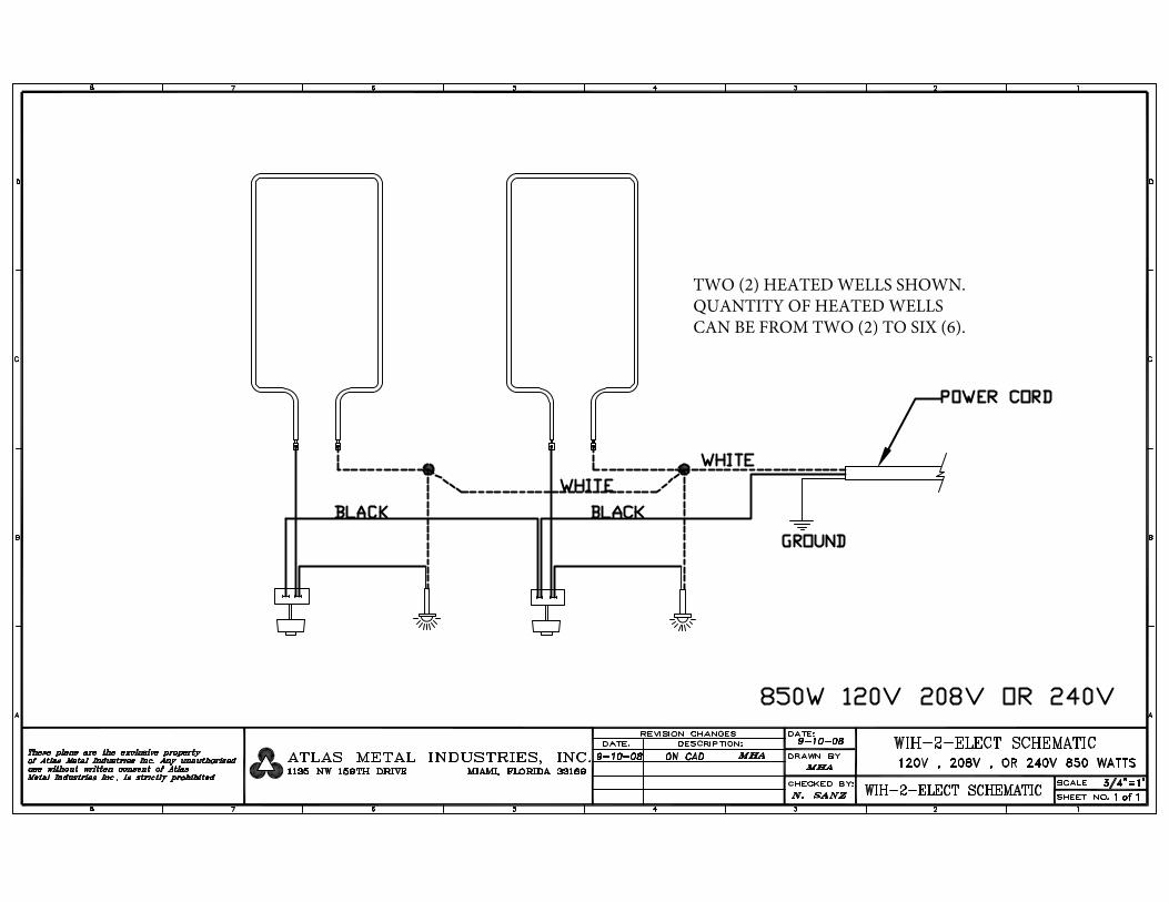
TWO (2) HEATED WELLS SHOWN.QUANTITY OF HEATED WELLSCAN BE FROM TWO (2) TO SIX (6).
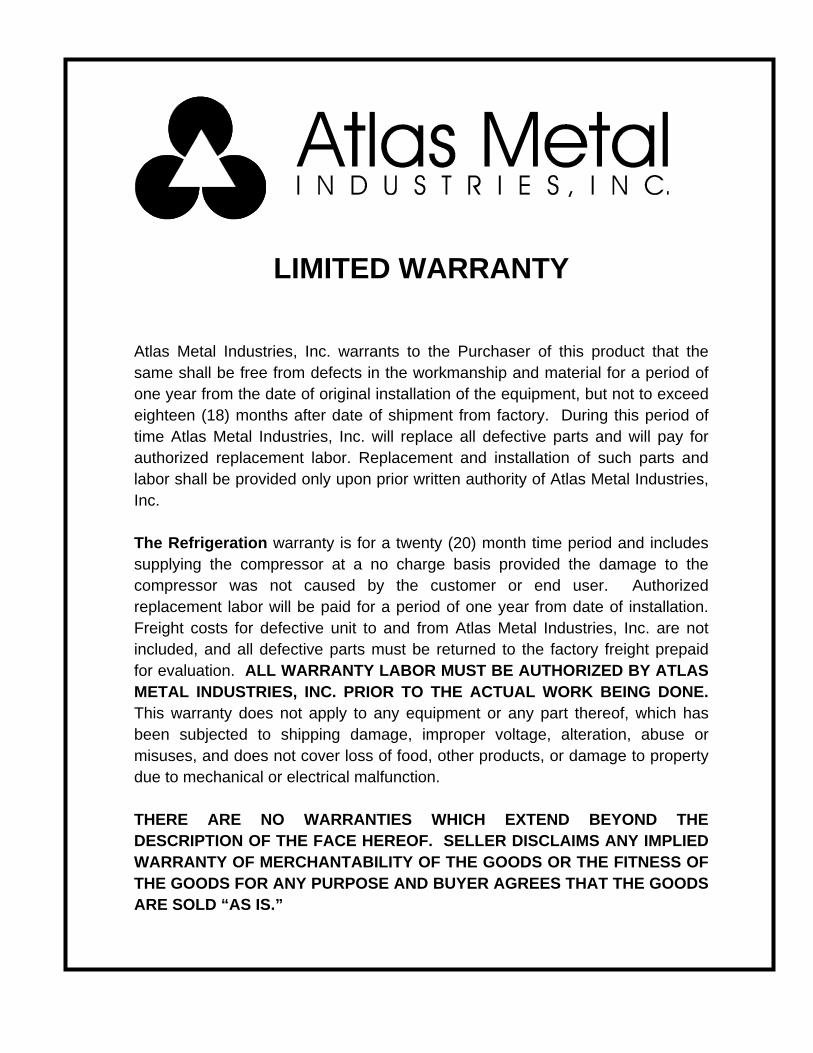
LIMITED WARRANTY Atlas Metal Industries, Inc. warrants to the Purchaser of this product that the same shall be free from defects in the workmanship and material for a period of one year from the date of original installation of the equipment, but not to exceed eighteen (18) months after date of shipment from factory. During this period of time Atlas Metal Industries, Inc. will replace all defective parts and will pay for authorized replacement labor. Replacement and installation of such parts and labor shall be provided only upon prior written authority of Atlas Metal Industries, Inc. The Refrigeration warranty is for a twenty (20) month time period and includes supplying the compressor at a no charge basis provided the damage to the compressor was not caused by the customer or end user. Authorized replacement labor will be paid for a period of one year from date of installation. Freight costs for defective unit to and from Atlas Metal Industries, Inc. are not included, and all defective parts must be returned to the factory freight prepaid for evaluation. ALL WARRANTY LABOR MUST BE AUTHORIZED BY ATLAS METAL INDUSTRIES, INC. PRIOR TO THE ACTUAL WORK BEING DONE. This warranty does not apply to any equipment or any part thereof, which has been subjected to shipping damage, improper voltage, alteration, abuse or misuses, and does not cover loss of food, other products, or damage to property due to mechanical or electrical malfunction. THERE ARE NO WARRANTIES WHICH EXTEND BEYOND THE DESCRIPTION OF THE FACE HEREOF. SELLER DISCLAIMS ANY IMPLIED WARRANTY OF MERCHANTABILITY OF THE GOODS OR THE FITNESS OF THE GOODS FOR ANY PURPOSE AND BUYER AGREES THAT THE GOODS ARE SOLD “AS IS.”

WARRANTY INFORMATION In order to have your invoice approved for payment by the factory, please note the following: _______________________________________________ An authorization number must be obtained from the factory prior to performing any warranty service. _______________________________________________ Atlas Metal will not approve excessive labor due to poor access to the unit being serviced. If design does not allow reasonable access, contact the factory. _______________________________________________ All travel time that exceeds 100 miles round trip must be authorized by the factory. _____________________________________________________________________________________
Thank You: Warranty service Dept.