series tire changer - nordic-lift as · 7 chapter 1 brief introduction 1.1brief introduction 887...
TRANSCRIPT

Series tire changer 887ITA/LC887A
(horizontal arm)
Instruction manual
Honor to customer
Quality innovation
Bright Technology Co.,ltd

2
Dear customers,
Very pleased that you will purchase and use the tire changer produced by our company
We are the company with reputation of quality. We sincerely wish to produce quality
goods under the ISO9001Quaality system and get the EU CE certificate to help you promote
your business.
model:
rated voltage: phase voltage hertz
factory code:
Technical standard code: Q/YGM001--2006
This product has been tested to be OK and permitted to be ex-work.

3
Warning
This instruction manual is the important part of the product. Please read it carefully
and keep It properly.
This machine is only applied to mount, demount and inflate the tire in the specified
scope and not for any other purpose.
The manufacturer will not be responsible for the damage arising from the improper
operation.
NOTE
This machine should be operated by the special trained qualified personnel. When
operating, the unauthorized personnel will be kept far away from the machine.
Please note the safety label stuck on the machine.
Operators should wear safety protective facilities such as working suit, protective
glasses, eye plug and safety shoes. Keep your hands and body from the movable parts
as possible as you can. Necklace, bracelet and loosen clothing may cause dangerous
to the operators.
Tire changer should be installed and fixed on the flat and solid floor. The more than
0.5m of distance from the rear and lateral side of the machine to the wall can guarantee
the perfect air flow and enough operation space.
Do not place the machine in the site of high temperature, high humidity, dust and with
flammable and corrosion gas.
Without the permission from the manufacturer, any change on the machine parts will
cause injury/damage to the machine/operator.
Pay special attention that the tire changer should be operated under the specified
voltage and air pressure.
If you want to move the tire changer, you should under the guidance of the professional
service personnel.

4
Safety Label Instruction Keep your hands far Carefully read operation When operation , wear
from tire when operation manual before operation the protective facilities
electrical shock! When rapid inflation,
ensure the wheel clamped.
Do not reach any part of your body under the demount tool. When operation,
do not wear long hair, loosen clothing and jewelries..
When breaking bead, the bead Breaking blade will quickly move leftwards.
When operation, not reach your hand under the falling objects.
Note: when press the tire, the opened clamp cylinder may injury the hand of the operator. Remember, do not touch the side wall of the tire. When clamping the rim, do not Reach your hand or other parts Of the body in between the clamp
& the rim.
Do not stand behind the column to Avoid the column from injuring the persons when swing.

5
Safety Label Position Diagram Pay attention to keep the safety labels complete. When it is not clear of missing, you should change the
new label. You should let the operators see the safety labels clearly and understand the meaning of the label.

6
Content Chapter 1 Brief Introduction-----------------------------------------------------------------------------------7
1.1 brief introduction------------------------------------------------------------------------------------------7
1.2 overall dimension-----------------------------------------------------------------------------------------7
1.3 technical parameter------------------------------------------------------------------------------------- 7
1.4 application--------------------------------------------------------------------------------------------------7
1.5 work environment----------------------------------------------------------------------------------------7
Chapter 2 Basic Construction and Operational parts--------------------------------------------------8
Chapter 3 Installation and Commission-------------------------------------------------------------------9
3.1 unpacking--------------------------------------------------------------------------------------------------9
3.2 installation of the parts detached----------------------------------------------------------------------10
3.3 air test--------------------------------------------------------------------------------------------------------13
Chapter 4 Demount/Mount-----------------------------------------------------------------------------------14
4.1 demount tire------------------------------------------------------------------------------------------------14
4.2 mount tire------------------------------------------------------------------------------16
4.3 common inflation----------------------------------------------------------------------------------------18
4.4 quick inflation---------------------------------------------------------------------------------------------18
Chapter 5 Repair and Maintenance------------------------------------------------------------------------19
Chapter 6 Transportation ------------------------------------------------------------------------------------21
Chapter 7 Electrical and pneumatic principle diagram------------------------------------------------22
Chapter 8 Common troubleshooting and solution------------------------------------------------------26

7
Chapter 1 Brief Introduction
1.1brief introduction
887 series tire changer is the tire changer featured with tilt and horizontal arm, suitable to mount, demount and
inflate all types of car tire with tube and tubeless. The operation is easy, convenient and safety. It is the
necessary equipment for the auto service shop and tire shop.
It includes two models: LC887A – common model 887ITA – with quick inflation
This model can be optional equipped with left assistant PL330B or right assistant AL335 or LC320B to mount
and demount the low profile and stiff tire.
1.2Overall dimension (exclude the accessories such as helper)
1.3Technical parameter
work pressure:8-10bar
motor:50Hz 0.8-1.1KW/220-380V
turntable speed:6.5rpm
noise:<70dB
1.4Application range
Model Max. wheel diameter Max. wheel width Rim diameter(inward clamp) Rim diameter(outward clamp)
887ITA 1030mm(40″) 380mm(15″) 10″~24″ 13″~26″
LC887A 1030mm(40″) 380mm(15″) 10″~24″ 13″~26″
1.5 work environment
temperature 0℃~45℃
RH 30~95%
Sea level max.1000M
Without dust and without gas easy to explosive and rusty
The space around machine is not less than indicated in Fig1
Model H(mm) L(mm) B(mm) NT( kg)
887ITA 1850 1265 890 As per packing list
LC887A 1850 1040 890 As per packing list

8
Forbidden to be used in the place containing the gas flammable!
Chapter 2 Basic construction and operational part
Fig2
1 vertical shaft spring 2 hand valve
3 hexangular shaft 4 tool head
5 clamping jaw 6 turntable
7 clamping cylinder 8 front face

9
9 pedal indication cover 10 column tilt pedal
11 clamp pedal 12 bead breaker pedal
13 turntable turning pedal 14 crowbar
15 breaker blade 16 bead breaker arm
17 bead breaker cylinder 18 bead breaker handle
19 oil-water separator 20 air tank
21 column 23 horizontal arm
Chapter 3 Installation and commission
Carefully read the manual before installation and the change on the parts of the machine without the
permission of the manufacturer can cause the damage to the machine;
Installation and commission person must have some knowledge relating to electrical;
Operator must under the special training and pass the examination;
You must carefully check the equipment list and contact the dealers or our company if you are in doubt;
To ensure the installation and commission complete successfully, please prepare the following common tools:
2pcs open spanners(10″), I pc socket key, 1pc hexangular spanner, 1pc pliers, 1pc screw, 1pc hammer and
1pc universal electric meter
3.1 Open the box
3.1.1 In accordance with the instruction on the package box, open the package box and remove the package
material and check if the machine is sounded and the accessories if completed.
3.1.2 Keep the package material far away from the working site and treat it well.
10
3.2 Install the parts detached.
3.2.1: Installation of the air tank
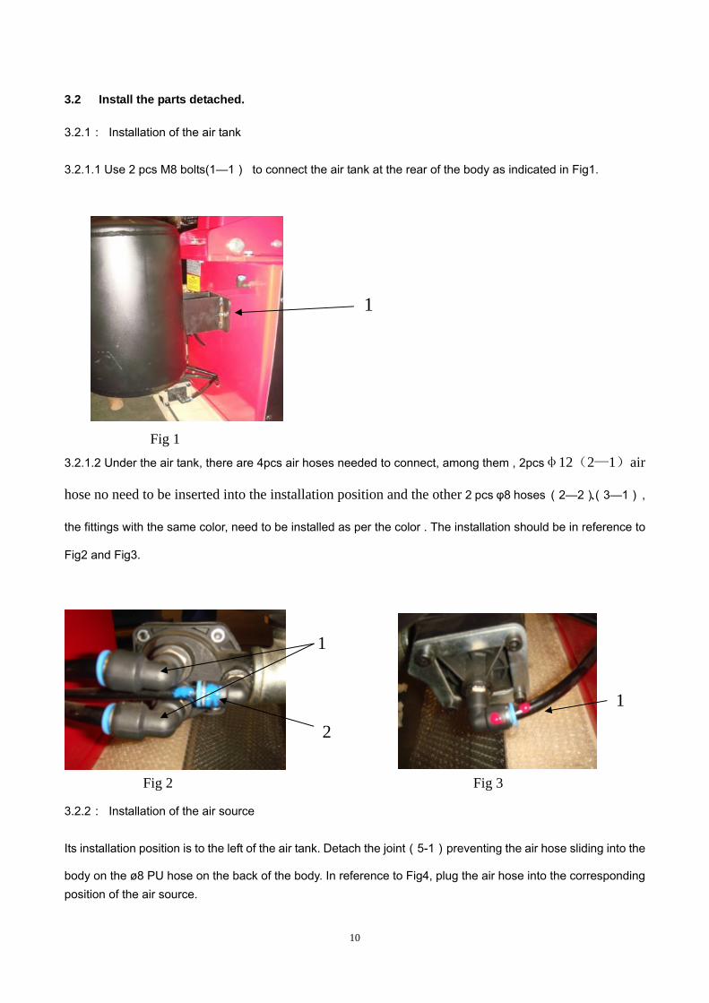
3.2.1.1 Use 2 pcs M8 bolts(1—1) to connect the air tank at the rear of the body as indicated in Fig1.
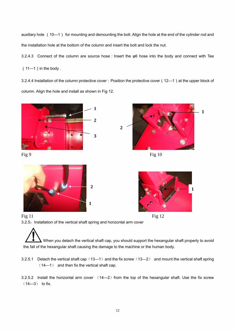
Fig 1 3.2.1.2 Under the air tank, there are 4pcs air hoses needed to connect, among them , 2pcsφ12(2—1)air
hose no need to be inserted into the installation position and the other 2 pcs φ8 hoses (2—2)、(3—1) ,
the fittings with the same color, need to be installed as per the color . The installation should be in reference to
Fig2 and Fig3.
Fig 2 Fig 3
3.2.2: Installation of the air source
Its installation position is to the left of the air tank. Detach the joint(5-1)preventing the air hose sliding into the
body on the ø8 PU hose on the back of the body. In reference to Fig4, plug the air hose into the corresponding position of the air source.
1
1
2
1

11
Fig4
3.2.3:Installation of bead breaking arm
3.2.3.1 As shown in Fig 7,align the installation hole of bead breaking arm(7—3)to the installation hole of bead
breaking arm bracket(7—2),plug in the pin shaft screw (7—1) and then tighten the lock nut(rotation moment
is 30~40 N·m).
3.2.3.2 As shown in Fig 6, plug cylinder rod (6—1)into the hole of bead breaking arm slide bush(6—3),then
tight the bushing and fix shaft assembly(6—2)together at the end of the cylinder rod.
3.2.3.3Hang the bead breaking arm spring(7—4)
Fig 6 Fig 7 Fig 8
3.2.4:Installation of the column assembly
3.2.4.1 Position the column(9—2)at the upper block of the body(9—3),The surface f the column that label
is stuck on should be forward. Align the installation hole and plug in the column rotation shaft(9—1),and use
the bolt to lock two sides.
3.2.4.2 Connect of column with the tilt back cylinder:On the left of the upper block of the column, there is an
2
1
1
3
1
2
3 4
12
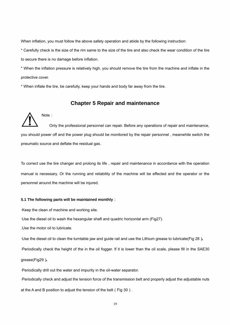
auxiliary hole (10—1) for mounting and demounting the bolt. Align the hole at the end of the cylinder rod and
the installation hole at the bottom of the column and insert the bolt and lock the nut.
3.2.4.3 Connect of the column are source hose:Insert the φ6 hose into the body and connect with Tee
(11—1)in the body .
3.2.4.4 Installation of the column protective cover:Position the protective cover(12—1)at the upper block of
column. Align the hole and install as shown in Fig 12.
Fig 9 Fig 10
Fig 11 Fig 12 3.2.5:Installation of the vertical shaft spring and horizontal arm cover
When you detach the vertical shaft cap, you should support the hexangular shaft properly to avoid
the fall of the hexangular shaft causing the damage to the machine or the human body. 3.2.5.1 Detach the vertical shaft cap(13—1)and the fix screw(13—2) and mount the vertical shaft spring
(14—1) and then fix the vertical shaft cap. 3.2.5.2 Install the horizontal arm cover (14—2)from the top of the hexangular shaft. Use the fix screw (14—3) to fix.
1
2
3
2
1
1
1 2

13
3.2.5.3 Adjust the set screw by the two sides of column and release the nuts by the two sides. Adjust the clearance between the heads of the screws and the side panel of the column to be 0.03mm(Fig 14A) to lock the nuts.
3.3Air test:
3.3.1 column tilt back
Connect the air and press down the lock valve button(Fig 2-2)to lock the horizontal arm. Step down column tilt
pedal(Fig 2-9)and the column tilt back by 25º. The tilt speed has been setup before ex-work at about 2seconds.
After longtime of use, the speed will be fast or slow and on this condition, you can use the speed valve at the
heads of the push-out cylinder to adjust. Loose the nut and turn adjust screw clockwise, the speed will be slow
and it will be slow if counterclockwise, tight the nut after adjust.
3.3.2 When the machine out of the factory, the air source fitting has been adjusted well and if you need to
change, you can readjust.
Pressure adjust: Lift up the pressure adjustable button( FIG15-1)and twist clockwise and the air pressure will
increase. Meanwhile, if counterclockwise, the air pressure will decrease.
1
2
1
2
3

14
Oil Feed:Use screw driver to twist the screw(FIG15-2). If clockwise, the oil dropping speed will slow. If
counterclockwise, it will become fast.
CHAPTER 4 DEMOUNT AND MOUNT TIRE
4.1 DEMOUNT TIRE
4.1.1 Deflate the air in the tire completely and pull out the core. Use the special tool to detach the weight on the
rim. (FIG16).
4.1.2 Place the tire between then bead breaking blade and tire pressing runner clog. Position the bead
breaking blade beside the lateral side of the tire (FIG17).Then step down the pedal to detach the rim from the
tire(fig2-12). Repeat the same operation on the other parts of the tire to make the tire completely detached from
the rim. To detach the lip smoothly, you can use the brush to spread the lubricant or thick soap liquid between
the lip and rim.
Place the wheel with the tire detached from the rim on the turntable and step the clamp pedal(fig2-11) to clamp

15
the rim. You can select the outer clamp (fig18)and inner clamp (fig19)to clamp the wheel according to the
different rim.
4.1.3 Move the hexangular shaft to the working position to make the demount tool close to the rim of the wheel.
The cylindrical roller in the demount tool will contact with the external rim of the rim and the bottom of the
demount tool will contact with the surface of the rim. Press the lock handle press button(fig2-2)to lock
horizontal arm and hexangular shaft and the hexangular shaft will automatically move upwards. The quadric
shaft will automatically backward a little to make the demount tool detached from the rim of the rim to avoid the
damage on the rim.(fig20).
The angle of the demount tool has been calibrated according to the standard rim( 13"). If handling the
extra-big or extra-small rim, you can reposition.

16
4.1.4 Use the crowbar to detach until the lip to the hump of
the demount tool (fig21). Step the turntable rotation pedal (fig2-13)to rotate the turntable clockwise until the rim
of the wheel fall off. If handling the tube tire, to avoid the damage on the tube, you should keep the nozzle of
the tire 10cm from the right side of the demount tool See fig22.
If the demount of the tire is jammed, please stop the machine immediately and then lift up the pedal to let the
turntable rotate counterclockwise to remove the resistance!
4.1.5 Take out the tube and then move up the lower lip to contact with the upper edge of the rim and repeat the
step of 4.1.4. Detach another lip(fig23). Step the column tilt pedal(fig2-10)and the column tilt backwards and
at this moment, you can take off the tire.
Necklace, bracelet and loosen clothing is easy to hook and injury the person
4.2 Mount tire:
Before mounting the tire, check if the rim and tire featured with the same dimension!
4.2.1 Clean up the oil and rust on the rim and lock the rim on the turntable. You can select the inner and outer clamp. But the tire detach groove must be in the relative higher position

17
4.2.2 Spread the lubrication liquid or soap liquid around the lip. Tilt the tire against the rim and keep the front
end upwards. Press down the column tilt pedal (fig2-10) to make the column return to the original position.
Move the demount head to firmly contacted rim(fig20). Position the left of the lip above the tail of the demount
tool and the right under the hump of the demount tool. See FIG 24.
4.2.3 Press down the right side of the tire as hard as you can and step turntable pedal(FIG2-13)to rotate the
turntable clockwise to guide the lip into the tire detach slot completely.
4.2.4 If there is tube, raise up the demount tool and put in the tube and position the core.
4.2.5 Mount the demount tool again. Adjust the position of the upper lip. Use the assistant press roller and
press to press the side of the tire to make partial of the lip into the tire detaching slot. Step the turntable rotation
pedal to rotate the tire. At this moment, continue pressing the lip just mounted on the rim. When 10~15cmof
the tire not into the rim, change to the step mode. And observe the condition of the tire to avoid the tear of the
tire. Once you feel there is any tear on the tire, release the pedal at once. Then lift up the pedal by instep to
make the motor rotate reverse. Make the tire restore to the original condition to mount again.

18
4.3 Common Inflation:
When inflating the tire, please be carefully and series obey the operation process. Check the air route to see if
the air connection is OK. This machine is equipped with an inflation gauge for monitoring the inflation of the tire
and the inflation pressure. (fig 2-22)
1. Loose the tire from the turntable.
2. Connect the inflation hose with the tire air core. See FIG26.
3. In the process of inflation, you should repeat stepping the inflation pedal. Confirm the pressure indicated on
the pressure gauge not exceed the scope specified by the manufacturer. In this machine, there is a pressure
decrease valve to keep the
inflation pressure not exceed 3.5bar. Customers can get different inflation pressure by adjusting the pressure
decrease valve according to their own requirement.
4. If the inflation pressure too high, you can press down the deflation press button on the inflation device to
reach the required air pressure.
4.4 Rapid Inflation(only for the machines with IT)
If the tubeless tire fit to the tire not tight, you can apply the rapid inflation first and then common
inflation:
1. Clamp the wheel and connect the inflation hose.
2. Step down the inflation pedal to the bottom position
(second gear) and quickly release the pedal when the tire
is full to the position of the first gear
3. Repeat stepping the pedal for many times to confirm
the pressure indicated on the pressure gauge not exceeds
the pressure specified by the manufacturer.
Note:This operation must be on the condition that the wheel is firmly clamped by the jaw,or there
will be danger to the life.
Warning!explosive!
19
When inflation, you must follow the above safety operation and abide by the following instruction:
* Carefully check is the size of the rim same to the size of the tire and also check the wear condition of the tire
to secure there is no damage before inflation.
* When the inflation pressure is relatively high, you should remove the tire from the machine and inflate in the
protective cover.
* When inflate the tire, be carefully, keep your hands and body far away from the tire.
Chapter 5 Repair and maintenance
Note:
Only the professional personnel can repair. Before any operations of repair and maintenance,
you should power off and the power plug should be monitored by the repair personnel , meanwhile switch the
pneumatic source and deflate the residual gas.
To correct use the tire changer and prolong its life,repair and maintenance in accordance with the operation
manual is necessary. Or the running and reliability of the machine will be effected and the operator or the
personnel around the machine will be injured.
5.1 The following parts will be maintained monthly:
·Keep the clean of machine and working site.
·Use the diesel oil to wash the hexangular shaft and quadric horizontal arm (Fig27).
.Use the motor oil to lubricate.
·Use the diesel oil to clean the turntable jaw and guide rail and use the Lithium grease to lubricate(Fig 28)。
·Periodically check the height of the in the oil fogger. If it is lower than the oil scale, please fill in the SAE30
grease(Fig29)。
·Periodically drill out the water and impurity in the oil-water separator.
·Periodically check and adjust the tension force of the transmission belt and properly adjust the adjustable nuts
at the A and B position to adjust the tension of the belt(Fig 30).

20
·Check all the connecting part and tight the loose bolts.
5.2 The adjustment on the clearance between the tool head and rim.
5.2.1Vertical clearance: Adjust the hexangular lock plate:
·Switch off the pneumatic source and detach the protective cover on the hexangular shaft.
·If the clearance if too much, we can adjust the nuts on the vertical hexangular shaft downward;
. If the clearance if too small we can adjust the nuts on the vertical hexangular shaft upward (Fig 31-1, 31-2);
·Connect the air source and observe the displacement after lock.
5.2.2 Horizontal clearance: Adjust the quadric lock plate:
·Switch off the air source and detach the protective cover at the upper end of the horizontal arm.
·Use spanner to loose the lock nut on the M6 screw at the two end.
.Adjust the M6 screw(Fig 31-3),meanwhile use your hand to push the quadric shaft until it runs smooth and
then lock the nut.

21
·Use the spanner to adjust the screw(Fig 31-4) in the middle and meanwhile lock the horizontal arm and
observe the displacement. When the displacement is 2mm,lock the nut.
CHAPTER 6 TRANSPORTATION When transport the machine must apply the original package and place according to the mark on the package.
The machine must be transported by the forklift with the corresponding tonnage(FIG32)and the stacked layer
will not exceed 3layers.

22
CHAPTER 7 ELECTCTRICAL AND PENUMATIC DRAWING 220V ELECTRICAL PRINCIPLE DRAWING 380V ELECTRICAL PRINCIPLE DRAWING
PE N L
SA
FU20A
电源线3X1.5mm2
QC拆胎机
内部连线
9 5 7 11 1 30
1 210 6 8 12 2 4
电机转向开关LW5D-1616A/500V
由用户完成的安装
220V 1.1KW 1400rpm
M1ph
U1 Z2 U2 V1
拆胎机单相电机220V接线原理图(通用)TIRE CHANGER 1-PHASE MOTOR(220V) WIRING DRAWING (UNIVERSAL)
MOTOR SWITH
INTERNAL
WIRING
BY CUSTOMER
POWER CABLE 3X1.5mm2

23
拆胎机
内部连线
由用户完成的安装
电源线4X1.5mm
电机转向开关
拆胎机三相电机 接线原理图 通用)
BY CUSTOMER
POWER CABLE 4X1.5mm2
INTERNAL WIRING
MOTOR SWITH
TIRE CHANGER 3-PHASE MOTOR(380V) WIRING DRAWING (UNIVERSAL)

24
电机转向开关
用户配置
Z1
L2
FU2
L1AC
110V/220V
FU1
12
21
40A/500V
0
LW5-40
9 75 111
2 410 6 8
U2U4U3
U1
M1~
FU1 FU2 40A
3
Z2
PE
U1 U2 U3 U4 Z1 Z2
220V
110V
兰 绿
黄 红
黄 绿 红 兰2 4 6 115
电压转换开关
2W30A
接线排
TB-2506L
600V/25A
1.1KW 4P110/220V 50 60HZ
PE
扒胎机双压电机连线图之二TIRE CHANGER DUAL VOLTAGE MOTOR ( II)
LINE BANK
MOTOR SWITH
VOTAGE SWITH
BY CUSTOMER
Blue
Red
Green
Yellow

25
φ80/20X80
φ70
/20X
310
φ70/2
0X310
φ186/20X150
12
34
56
4 φ66/66.5X
16
φ66/66.5X
16
26
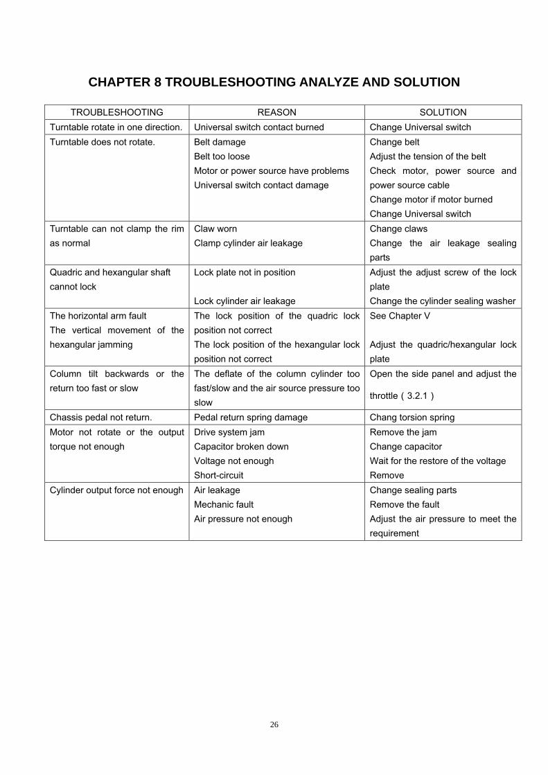
CHAPTER 8 TROUBLESHOOTING ANALYZE AND SOLUTION
TROUBLESHOOTING REASON SOLUTION Turntable rotate in one direction. Universal switch contact burned Change Universal switch Turntable does not rotate. Belt damage
Belt too loose Motor or power source have problems Universal switch contact damage
Change belt Adjust the tension of the belt Check motor, power source and power source cable Change motor if motor burned Change Universal switch
Turntable can not clamp the rim as normal
Claw worn Clamp cylinder air leakage
Change claws Change the air leakage sealing parts
Quadric and hexangular shaft cannot lock
Lock plate not in position Lock cylinder air leakage
Adjust the adjust screw of the lock plate Change the cylinder sealing washer
The horizontal arm fault The vertical movement of the hexangular jamming
The lock position of the quadric lock position not correct The lock position of the hexangular lock position not correct
See Chapter V Adjust the quadric/hexangular lock plate
Column tilt backwards or the return too fast or slow
The deflate of the column cylinder too fast/slow and the air source pressure too slow
Open the side panel and adjust the
throttle(3.2.1)
Chassis pedal not return. Pedal return spring damage Chang torsion spring Motor not rotate or the output torque not enough
Drive system jam Capacitor broken down Voltage not enough Short-circuit
Remove the jam Change capacitor Wait for the restore of the voltage Remove
Cylinder output force not enough Air leakage Mechanic fault Air pressure not enough
Change sealing parts Remove the fault Adjust the air pressure to meet the requirement

27
- Appendix- LC SERIES MACHINE OIL SAFETY DATA SHEET
MOBIL XHP 222
SAE30#
LUBRICATION OIL ITEM QUALITY STANDARD
density 15℃ 0.893
Flash point 224
Pour point ℃ -18
viscosity 40℃ 100
viscosity 100℃ 11.2
Viscosity index 97
2# LITHIUM BASE GREASE ITEM QUALITY STANDARD
Penetration rate mm/10 278
dropping point ℃ 187
copper corrosion 100℃ 24h No change
oxidize stability(99℃ 100h) 0.2
anticorrosion(52℃ 48h) 1 level
similarity viscosity(-15℃、 10S¯¹)/(Pa·S) 800
water lose(35℃ 1h) % 8
ITEM QUALITY STANDARD
Penetration rate25℃ mm/10 280
dropping point ℃ 280
anticorrosion passed Basic oil viscosity 220 oxidize stability 100h pressure-drop kpa 35 water lose percentage79% 5 copper corrosion 1A

28
CKC460 INDUSTRIAL GEAR OIL
ITEM QUALITY STANDARD
Viscosity 40℃ 461
Viscosity index 92
Flash point ℃ 212
Freezing point ℃ -26
copper corrosion100℃ 3h 1A
mechanical impurity 0.007 Pour point -10