series sff & sfr - · pdf fileseries sff & sfr sff / sfr ... en 1503-2: valves -...
TRANSCRIPT
Page 1 of 16
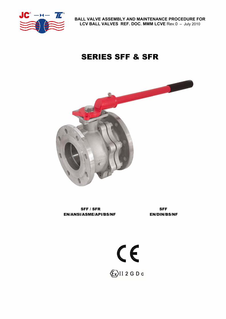
BALL VALVE ASSEMBLY AND MAINTENANCE PROCEDURE FOR LCV BALL VALVES REF. DOC. MMM LCVE Rev.0 – July 2010
SERIES SFF & SFR
SFF / SFR SFF EN/ANSI/ASME/API/BS/NF EN/DIN/BS/NF

Page 2 of 16
BALL VALVE ASSEMBLY AND MAINTENANCE PROCEDURE FOR LCV BALL VALVES REF. DOC. MMM LCVE Rev.0 – July 2010
REVIEW CONTROL
PROCEDURE REF.: DOC. MMM LCVE
REV. DATE CARRIED OUT BY APPROVED BY DESCRIPTION noitidE ts1 rodejeT.J oibuR .J 0102/70/91 0

Page 3 of 16
BALL VALVE ASSEMBLY AND MAINTENANCE PROCEDURE FOR LCV BALL VALVES REF. DOC. MMM LCVE Rev.0 – July 2010
CONTENTS
1.- APPLICABLE RANGE................................................................................................... Page 4
2.- GENERAL INFORMATION ...................................................................................... Pages 5-9
STATEMENT DESCRIPTION OF APPLICABLE EQUIPMENTSTECHNICAL STANDARDSSCOPE OF USE ENVIRONMENTAL CONSIDERATIONSDESIGN CONDITIONS
3.- INSPECTION AT RECEPTION AND STORAGE ....................................................... Page 10
4.- INSTALLATION ................................................................................................... Pages 10-11
5.- PREVENTIVE MAINTENANCE .................................................................................. Page 11
6.- MAINTENANCE OPERATIONS ................................................................................. Page 12
PRECAUTIONS
7.- REASONS FOR PARTS REPAIR AND REPLACEMENT .................................. Pages 12-14
LEAKAGE THROUGH THE PACKINGLEAKAGE THROUGH THE BODY SEALCHANGE OF PACKINGCHANGE OF SEATS, PACKING AND SEALS
8.- MAXIMUM GLAND NUT TIGHTENING TORQUE ..................................................... Page 14
9.- NUTS AND BOLTS TIGHTENING TORQUE ............................................................. Page 15
10.- VALVE EXPLOSION VIEW ……………………………………………………................ Page 16

Page 4 of 16
BALL VALVE ASSEMBLY AND MAINTENANCE PROCEDURE FOR LCV BALL VALVES REF. DOC. MMM LCVE Rev.0 – July 2010
1.- APPLICABLE RANGE
ANSI/ASME/API/BS/NF RANGE
SFF SERIES SFR SERIES
SOFT SEATS
FIGURES
315
330
415
430
SOFT SEATS
FIGURES
EN/DIN/BS/NF RANGE
SFF SERIES SFR SERIES
SOFT SEATS
FIGURES
254
254L
256
256L
SOFT SEATS
FIGURES

Page 5 of 16
BALL VALVE ASSEMBLY AND MAINTENANCE PROCEDURE FOR LCV BALL VALVES REF. DOC. MMM LCVE Rev.0 – July 2010
2.- GENERAL INFORMATION
2.1 STATEMENT
ICP SFF and SFR Series Ball Valves have been designed and manufactured for the use, circulation and control of fluids in those industrial processes in which conditions are suitable for the performance levels of the valves, according to the applicable standards.
Steel & Stainless Steel Valves DN greater than 25
ICP VALVES states that ICP valves covered by this certificate have been designed and manufactured according to the following European Directive requirements:
- European Pressure Equipment Directive 97/23 EC: Evaluation Procedure of Conformity Mod H Cat III, certified by Bureau Veritas nº CE-PED-H-JCV 001-04-ESP. Marking CE0062 Cat III Mod H.
- Directive 94/9 EC ATEX, classification Group II, Cat 2 for use in explosive atmospheres, areas 1,2 & 21,22. Evaluation of conformity according to Appendix VIII. Marking CE Ex II2GDc.
Applied harmonized and non-harmonized technical Standards:
- EN 10213, EN 10204, EN 12266-1, EN 15848-1 & (2)*, EN ISO 17292, EN 1983, EN 19:2002, others see ICP’s Catalogue and Assembly & Maintenance Procedures.
- EN 13463-1:2001, EN 1127-1.
The electrical and mechanical extras are not covered by this statement and will have to carry their own in order to be assembled with ICP valves.
Steel & Stainless Steel Valves DN lower than 32
ICP states that ICP valves covered by this certificate have been designed and manufactured according to the following European Directive requirements:
- European Pressure Equipment Directive 97/23 EC: classified according article 3, part 3, cat SEP, must not carry the CE label.
- Directive 94/9 EC ATEX, classification Group II, Cat 2 for use in explosive atmospheres, areas 1,2 & 21,22. Evaluation of conformity according to Appendix VIII. Marking CE Ex II2GDc.
Applied harmonized and non-harmonized technical Standards:
- EN 10213, EN 10204, EN 12266-1, EN 15848-1 & (2)*, EN ISO 17292, EN 1983, EN 19:2002, others see ICP’s Catalogue and Assembly & Maintenance Procedures.
- EN 13463-1:2001, EN 1127-1.
The electrical and mechanical extras are not covered by this statement and will have to carry their own in order to be assembled with ICP valves.
The suitability of the materials and the design of the type of valve in terms of their working conditions is the responsibility of the end user of the valve.
* on request

Page 6 of 16
BALL VALVE ASSEMBLY AND MAINTENANCE PROCEDURE FOR LCV BALL VALVES REF. DOC. MMM LCVE Rev.0 – July 2010
SFF & SFR SERIES FOR EN/ANSI/ASME/API/BS/NF DESIGN
DESCRIPTION OF APPLICABLE EQUIPMENTS
Category III Module H (ISO EN 9001)
Series Body Ball Bore Class/ISO PN ICP Fig. DN FLANGES
150 / ISO PN 20
315415 1/2”- 8”
SFF Two pieces Floating Full
300 / ISO PN 50
330430 1/2”- 8”
RF / STOCKFINISH
Applicable Technical Standards:
EN 19: Marking of general purpose industrial valves. EN 558-2: Face-to-face and centre-to-face dimensions of metal valves for use in flanged pipe systems
Part 2: Class-designated valves. EN 1503-2: Valves - Materials for bodies, bonnets and covers - Part 2: Steels other than those
specified in European Standards.
Fire Safe certification: BS 6755 Part 2 / API 607 4TH Edition / API 6FA / ISO 10497:2004 Valves design: API 6D / ASME B 16.34 / EN 1983 / EN ISO 17292 Body design: ASME VIII Div 1 Shell thickness: ASME B 16.34 / BS 5351
5.61 B EMSA :segnalFFace-to-face dimensions: ASME B 16.10 / API 6D Shell finishing quality: MSS SP 55 Wetted parts materials & bolting: NACE MR 01.75
29271 OSI NE / D6 IPA / 91 NE :gnikraMPressure testing: API 598 / ISO 5208 / EN 12266 Actuator mounting flange: ISO - EN 5211 Fugitive emissions: EN 15848-1 & (2)*
* on request

Page 7 of 16
BALL VALVE ASSEMBLY AND MAINTENANCE PROCEDURE FOR LCV BALL VALVES REF. DOC. MMM LCVE Rev.0 – July 2010
SFF SERIES FOR EN/DIN/BS/NF DESIGN
DESCRIPTION OF THE APPLICABLE EQUIPMENTS
Category III Module H (ISO EN 9001)
Series Body Ball Bore ISO PN ICP Fig. DN FLANGES
16 256 65 - 200 Short (F18) Split body
40 254 15 - 150
16 256L 65 - 200 SFF
Long (F1) Split body
Floating Full
40 254L 15 - 200
RFForm C
Applicable Technical Standards
EN 19: Marking of general-purpose industrial valves. EN 558-1: Face-to-face and centre-to-face dimensions of metal valves for use in flanged pipe systems. Part 1: PN-designated valves EN 1503-1: Valves - Materials for bodies, bonnets and covers - Part 1: Steels specified in European Standards.
Fire Safe certification: BS 6755 Part 2 / ISO 10497:2004 Valves design: EN 1983 / EN ISO 17292 Body design: DIN 3840 Shell thickness: BS 5351 Flanges: EN 1902-1 Face to face dimensions: EN 558-1 Shell finishing quality: MSS SP 55 Marking: EN 19 / ISO EN 17292 Pressure testing: ISO 5208 / EN 12266 Actuator mounting flange: DIN 3337 / ISO - EN 5211 Fugitive emissions: EN 15848-1 & (2)*
* on request

Page 8 of 16
BALL VALVE ASSEMBLY AND MAINTENANCE PROCEDURE FOR LCV BALL VALVES REF. DOC. MMM LCVE Rev.0 – July 2010
SCOPE OF INSTALLATION ACCORDING TO THE TYPE OF FLUID (DANGEROUS FOR THE ENVIRONMENT OR HUMAN HEALTH)
GROUP 1 CLASSIFICATION
.- The incorporation of additional safety elements “Double packing” is recommended for the range of products included in Group 1.
.- The use of valves without additional safety devices in Group 1 will be the responsibility of the user or the purchaser, as well as the advisability of installing leakage detection systems.
GROUP 2 CLASSIFICATION
.- Carbon Steel valves will not be used in corrosive fluids lines
Warning is given that when the use of fluids that could cause damages to human's health, environment or property is expected, then the necessary safety elements to prevent risks must also be used!
ENVIRONMENTAL CONSIDERATIONS:
According to the premises marked by the ISO 14000 Regulations and the environmental policy of ICP Valves.
The recyclability of the components that form part of ICP valves is the following:
Recyclable components:
Metal parts, PTFE (hard), plastic plug (low-density polyethylene).
Non-recyclable components:
PTFE mixed with other compounds (Glass-fiber, graphite, etc…), nylon, graphite and graphite mixed with metal.

Page 9 of 16
BALL VALVE ASSEMBLY AND MAINTENANCE PROCEDURE FOR LCV BALL VALVES REF. DOC. MMM LCVE Rev.0 – July 2010
DESIGN CONDITIONS
SFF & SFR SERIES FOR CLASS-DESIGNATED VALVES API 6D / ANSI B 16.34 / BS 5351 / NF E 29-470
CLASS 150 - ISO PN 20Unit A216 WCB A351 CF8M
Class psig 150
Design Temp. ºC -29 / 230 (see note 1)
Design Pressure psi/N/mm² 285/1.965 275/1.896
Test Temp. Ambient
Test Pressure Psi/N/mm² 428/2.947 412/2.844
Castings Quality Factor 0.8
CLASS 300 ISO PN 50Unit A216 WCB A351 CF8M
Class psig 300
Design Temp. ºC -29 / 230 (see Note 1)
Design Pressure Psi/N/mm² 740/5.102 720/4.964
Test Temp. Ambient
Test Pressure Psi/N/mm² 1110/7.653 1080/7.446
Castings quality factor 0.8
Note 1: Seats in PTFE. For other types of seats, consult the manufacturer’s catalogue. Note 2: On request in DIN/EN materials or AD-Merkblatt certificates.
SFF & SFR SERIES FOR PN-DESIGNATED VALVES DIN 3357 / BS 5351 / NF E 29-470
ISO PN 16 Unit 1.0619 1.4408
PN Bar 16
Design Temp. ºC (see Note 1) -10 / 230 -50 / 230
Design Presure Bar / N/mm² 16 / 1,6 16 / 1,6
tneibmA .pmeT tseT
Test Pressure Bar / N/mm² 24 / 2,4 24 / 2,4
Safety Factor (Casting) PN (2), PE (1,5)
ISO PN 40 Unit 1.0619 1.4408
PN Bar 40
Design Temp. ºC (see Note 1) -10 / 230 -50 / 230
Design Pressure Bar / N/mm² 40 / 4,6 40 / 4,6
tneibmA .pmeT tseT
Test Pressure Bar / N/mm² 60 / 6,6 60 / 6,6
Safety Factor (Casting) PN (2), PE (1,5)

Page 10 of 16
BALL VALVE ASSEMBLY AND MAINTENANCE PROCEDURE FOR LCV BALL VALVES REF. DOC. MMM LCVE Rev.0 – July 2010
3.- INSPECTION AT RECEPTION AND STORAGE
3.1 All valves will be examined on reception, to ensure that they have not suffered any damages during transport, and the supplier will immediately be informed of any damages observed.
3.2 The valves leave the factory in open position as a measure of protection and to ensure that no foreign body can damage the ball, except fail to close actuated valves (actuator normally in closed position).
3.3 WARNING!The valves will be stored under cover and protected from inclement weather conditions and foreign bodies.
3.4 The valves will not be unpacked until they are to be definitively installed, except for purposes of inspection. After inspection they will be packed again.
4.- INSTALLATION
4.1 The handling and transporting of the valves must be carried out with extreme precaution and using the necessary and adequate means on the basis of their size and weight, in this way avoiding any risks to the persons that handle them.
4.2 WARNING! Never use the wrench to hold the valve during handling, assembly or transport.
Check the condition of the valve, firstly to detect any possible damages caused during their transport and/or handling.
Likewise inspect the inside of the valve, as well as the interior of the pipe that connects up to the valve. It is of utmost importance that there are no foreign bodies that could damage the valve seats, insofar as these parts are fundamental to the correct operation of the valve.
WARNING!When it is known or assumed that the valve is to be installed at a collection point for waste, such as welding slag, rust or scale, protective filters or screens must be placed, temporarily or definitively (depending on the installation), upstream, before connection with the valve.
The valve must be installed in such a way that it is accessible for the necessary periodic inspection and maintenance required guaranteeing the performance levels for which it has been designed.
ICP Standard SFF & SFR series constructions up to –20ºC have been designed without fluid direction preference – “They are Bi-directional”
When the construction of the valve, even being of the same SFF & SFR Series, is specified to work at temperatures below – 20 ºC and down to – 46 ºC (LOW TEMPERATURE), the valves will be “Unidirectional” and will have an arrow or identification plate indicating the flow direction.
The valve can be installed with the stem in any position, although it is recommended that this be done in a vertical position, with the stem upwards.
Page 11 of 16
BALL VALVE ASSEMBLY AND MAINTENANCE PROCEDURE FOR LCV BALL VALVES REF. DOC. MMM LCVE Rev.0 – July 2010
WARNING! The valves must not support stress from the piping, the installation must be carried out ensuring correct alignment and parallelism in order to ensure that it is not subject to any unexpected stress.
Make sure when installing the valve that the flange seal that connects up to the valve is correctly fitted, following the seal manufacturer’s instructions, also ensuring that it is compatible with the circulating fluid.
IMPORTANT! After installation run a final check on the valve, opening and closing it to make sure that it is working perfectly.
WARNING! Make sure that the fluid used in cleaning operations and the way in which the cleaning is done are compatible with the installed valve.
Having finished the final cleaning operations prior to bringing the valve on-line, if filters have been installed they can be removed or, on the other hand if the user considers that rust or scale formations may be encountered, they must be left permanently in place.
IMPORTANT! When ball valves are destined to end line, you should reduce the hydrostatic proof pressure of the line to 1,1 Rating pressure.
5.- PREVENTIVE MAINTENANCE
5.1 Preventive maintenance operations essentially consist of periodic inspections to ensure that the valve is working correctly.
5.2 The valves must be opened and closed at least once every 6 months and, should such be required on the basis of the fluid or the application of the valve and its importance, opening and closing check plans will have to be established for shorter periods.
5.3 The user will be responsible for establishing opening and closing plans that are adequate for the work conditions and the fluids used!
5.4 WARNING! Never leave the valves open or closed for a long period of time.
5.5 A very high torque increase could be due to the inclusion of foreign bodies in the seats. It is important not to force the valve! Proceed with an inspection of the seats in order to avoid damaging the ball.
5.6 We advise replacement of the seals and the seats whenever an in-depth revision of the installation is made.

Page 12 of 16
BALL VALVE ASSEMBLY AND MAINTENANCE PROCEDURE FOR LCV BALL VALVES REF. DOC. MMM LCVE Rev.0 – July 2010
6.- MAINTENANCE OPERATIONS
PRECAUTIONS BEFORE DISASSEMBLY!!
Make sure that the line has been closed and depressurised. Open and close the valve several times in order to release the pressure and drain the valve cavity.
WARNING! Wear protective clothing adequate for the circulating fluid. (Comply with the safety guidelines laid down by the company!)
Remove the valve from the line in the closed position, and clean off any remaining fluid.
The replacement of parts must be done using original ICP spare parts!
The manufacturer will not be responsible for the malfunctioning of the valve if original ICP parts are not used!
7.- REASONS FOR PARTS REPAIR AND REPLACEMENT
7.1 LEAKAGE THROUGH THE PACKING
7.1.1 If leakage is detected through the packing (8), tighten the gland nut (12) by an 1/8 of a turn. Repeat this operation if leakage persists. If there is still leakage substitute the packing (8).
7.2 LEAKAGE THROUGH THE BODY SEAL
7.2.1 If leakage is detected through the body seal (17), then this seal must be changed. Follow the instructions point 7.4.
7.3.- CHANGE OF PACKING
We recommend that when the change of packing (8) is necessary, to substitute as well the seats (4), body seal (17) and stem thrust washers (6). However, if due to process needs it is not possible to disassembly the valve from the line, follow the sequence below:
DISASSEMBLY
7.3.1 Make sure that the installation is not under pressure.
7.3.2 Disassembly the handle (14) or actuator, open the rib of the locking washer (11), in order to remove the gland nut (12) and the disk springs (10).
7.3.3 Remove the thrust washer (13) and the gland ring (9). Remove the packing (8) without damaging the stem (5) and body (1) surfaces.

Page 13 of 16
BALL VALVE ASSEMBLY AND MAINTENANCE PROCEDURE FOR LCV BALL VALVES REF. DOC. MMM LCVE Rev.0 – July 2010
ASSEMBLY
7.3.4 Fit a new packing (8) in its body (1) housing.
7.3.5 Place the gland ring (9), the new thrust washer (13), the disk springs (10), the locking washer (11) and tighten the gland nut (12) to the torque specified in point 8.8.
7.3.6 Before refitting the handle (14) or actuator, check the valve under pressure to verify the tightness of the packing (8). If there is leakage see point 7.1.1.
7.3.7 Assembly the handle (14) or actuator.
7.4.- CHANGE OF SEATS, PACKING AND SEALS
DISASSEMBLY
7.4.1 Verify that the installation is not under pressure.
7.4.2 Disassembly the valve from the line. If the circulating fluid is noxious or inflammable, precautions must be taken to avoid accidents.
7.4.3 Unfasten the nuts (16) of the body-body connector, bearing in mind that there may be fluid trapped in the body cavity (1). Separate the body connector (2) from the body (1).
7.4.4 Remove the seat (4) from the body connector and the seal (17) from the body-body connector.
7.4.5 Turn the ball (3) to the closed position and remove it from body (1). Clean the outside surfaces, the bore and slot, verifying that the pressure relief hole situated at the bottom is not blocked. Check the exterior surface of the ball, particularly the area in contact with the seats and the radius of transition between the exterior surface and the bore. If the ball’s surface or slot are damaged, replace the ball for a new one.
7.4.6 Remove the seat (4) from the body (1).
7.4.7 Disassembly the stem (5). For this operation follow steps 7.3.2 and 7.3.3. Remove the stem (5) through from the inside of the body (1). Remove the thrust washer in PTFE with glass fibre (6). The stem (5) incorporates an o-ring (7) that will have to be substituted.
7.4.8 Clean the inside surfaces of the body (1) and body connector (2), specially the housing areas of the seats, body seal, thrust washer and packing.
7.4.9 Clean and check the stem. Verify that the antistatic device works, pushing the balls inwards in their housing and checking that they return to their original position. If any of these balls is blocked or the surface of the stem damaged, substitute the stem by a new one.
ASSEMBLY
Make sure that the spare parts are ICP original, with the same materials and dimensions as the parts to be replaced.

Page 14 of 16
BALL VALVE ASSEMBLY AND MAINTENANCE PROCEDURE FOR LCV BALL VALVES REF. DOC. MMM LCVE Rev.0 – July 2010
WARNING!! If the valve has to be degreased (Oxygen Service, Hydrogen Peroxide, etc.),
consult the manufacturer.
7.4.10 Place the thrust washer (6) in the stem (5). Place the O-ring (7) in the stem’s slot.
7.4.11 Insert the stem (5) in its housing through the inside of the body (1).
7.4.12 Assembly the packing (8) and rest of parts according points 7.3.4, 7.3.5 y 7.3.6
7.4.13 Place a new seat (4) in the body (1).
7.4.14 Turn the stem (5) to the closed position so that it can be introduced in the slot of the ball (3). Assembly the ball (3) in closed position, making sure that there is no play between the slot and the stem.
7.4.15 Insert in the body connector (2) the other seat (4) and the seal (17) in the body’s (1) housing.
7.4.16 Adjust the body connector (2) over the body (1). Verify that the holes of both flanges are in the same position with respect to the stem’s symmetry of the valve.
7.4.17 Screw the nuts (16), following the adequate sequence.
7.4.18 Assembly the handle (14) or actuator.
7.4.19 Before re-assembling the valve in the line, test it in half-open position to verify the tightness of the packing (8) and body seal (17) and then close it and test the tightness of the seats (4).
8.- MAXIMUM GLAND NUT TIGHTNESS TORQUE IN m.Kp.
Nominal Diameter Graphite Packing
2.2 51
2.2 02
2.2 52
5.2 23
4 04
4 05
7 56
8 08
8 001
9 521
9 051
32 002

Page 15 of 16
BALL VALVE ASSEMBLY AND MAINTENANCE PROCEDURE FOR LCV BALL VALVES REF. DOC. MMM LCVE Rev.0 – July 2010
9.- TIGHTNESS TORQUE CHART OF THE BOLTS / NUTS OF THE BODY-BODY CONNECTOR. VALUES IN mKg.
UNC THREAD CLASS ASSEMBLY (*)
Elastic Limit 0.2% (Kg/mm²) 21 55
Material B8/B8M B7M
ØBolt
3/8” 1.57 4
7/16” 2 5.5
1/2” 2.6 7
9/16” 4.2 11
5/8” 6.3 16.5
3/4” 10 27
7/8” 16.8 43
1” 25 72
(*) Calculation with a friction coefficent of 0.12 and 75%of the elastic limit.

Page 16 of 16
BALL VALVE ASSEMBLY AND MAINTENANCE PROCEDURE FOR LCV BALL VALVES REF. DOC. MMM LCVE Rev.0 – July 2010
10.- VALVE EXPLOSION VIEW
HANDLE FROM DN-4”TO 8”
Page 17 of 16
BALL VALVE ASSEMBLY AND MAINTENANCE PROCEDURE FOR LCV BALL VALVES REF. DOC. MMM LCVE Rev.0 – July 2010
Cantàbria, 2. Pol. Ind. Les Salines 08830 Sant Boi de Llobregat
Barcelona (España)Tel. (+34) 936 54 86 54 Fax (+34) 936 54 86 55