series miniature inductive amplifier built-in proximity sensor · gl-6 miniature inductive...
TRANSCRIPT

GL-6Miniature Inductive Proximity Sensor
High performance insurprisingly small body at low cost
572
SERIES
Amplifier Built-in
Extremely small
Close mounting
Low price Operation indicator
The GL-6 is available at a surprisinglylow price.
Despite its compactness, GL-6 in-corporates an operation indicator(orange) for operation check.
Mountable in a tight space as the sensor isjust 6619 mm 0.2360.2360.748 inin volume. It is optimum for use as acomponent in an equipment.
Two sensors can be mounted closetogether because different frequencytype are available.

573
GL-6APPLICATIONS
Type
Fron
t sen
sing
Top
sens
ing
Appearance (mm in) Sensing range (Note 1) Model No. (Note 2) Output operationOutput
Observing table over-run Sensing cam positions
ORDER GUIDE
GL-6F
GL-6FI
GL-6FB
GL-6FIB
GL-6H
GL-6HI
GL-6HB
GL-6HIB
Normally open
Normally closed
Normally open
Normally closed
NPNopen-collectortransistor
Maximum operationdistance
Stable sensing range
(0 to 1.2 mm 0 to 0.047 in)
1.6 mm 0.063 in
Notes: 1) The maximum operation distance stands for the maximum distance for which the sensor can detect the standard sensing object.Notes: 1) The stable sensing range stands for the sensing range for which the sensor can stably detect the standard sensing object even if
there is an ambient temperature drift and/or supply voltage fluctuation.Notes: 2) ‘I’ in the model No. indicates a different frequency type.
• Table of Model Nos.
Type
Fron
t sen
sing
Top
sens
ing
Standard 5 m 16.404 ft cable length type
GL-6F
GL-6FI
GL-6FB
GL-6FIB
GL-6H
GL-6HI
GL-6HB
GL-6HIB
GL-6F-C5
GL-6FI-C5
GL-6FB-C5
GL-6H-C5
GL-6HI-C5
GL-6HB-C5
OPTION
Designation
Sensor mountingbracket
Model No.
MS-GL6-2
DescriptionSensor mounting bracket• MS-GL6-2
Screw, nut or washer arenot attached.
The brackets are useful to mountsensors side by side.
Accessory• MS-GL6-1 (Sensor mounting bracket)
5 m 16.404 ft cable length type5 m 16.404 ft cable length type (standard: 1m 3.281 ft) is also available.

574
GL-6SPECIFICATIONS
Max. operation distance (Note)
Stable sensing range (Note)
Standard sensing object
Hysteresis
Supply voltage
Current consumption
Output
Utilization category
Output operation
Max. response frequency
Operation indicator
Pollution degree
Protection
Ambient temperature
Ambient humidity
EMC
Voltage withstandability
Insulation resistance
Vibration resistance
Shock resistance
Temperature characteristics
Voltage characteristics
Material
Cable
Cable extension
Weight
Accessory
Model No.
Type
Miniature
1.6 mm 0.063 in 15 %
0 to 1.2 mm 0 to 0.047 in
Iron sheet 1212t 1 mm 0.4720.472t 0.039 in
15 % or less of operation distance
12 to 24 V DC % Ripple P-P10 % or less
15 mA or less
NPN open-collector transistor• Maximum sink current: 50 mA• Applied voltage: 30 V DC or less (between output and 0 V)• Residual voltage: 1 V or less (at 50 mA sink current)
0.4 V or less (at 16 mA sink current)
DC-12 or DC-13
400 Hz
Orange LED (lights up when the output is ON)
3 (Industrial environment)
IP67 (IEC), IP67g (JEM)
10 to55 C 14 to131 F, Storage:30 to80 C 22 to176 F
45 to 85 % RH, Storage: 35 to 95 % RH
EN 50081-2, EN 50082-2, EN 60947-5-2
1,000 V AC for one min. between all supply terminals connected together and enclosure
50 MΩ, or more, with 250 V DC megger between all supply terminals connected together and enclosure
10 to 55 Hz frequency, 1.5 mm 0.059 in amplitude in X, Y and Z directions for two hours each
1,000 m/s2 acceleration (100 G approx.) in X, Y and Z directions for three times each
Over ambient temperature range10 to55 C 14 to131 F: within10 % of sensing range at 20 C 68 F
Within2 % for10 % fluctuation of the supply voltage
Enclosure: Polyalylate
0.08 mm2 3-core oil, heat and cold resistant cabtyre cable, 1 m 3.281 ft long
Extension up to total 100 m 328.084 ft is possible with 0.3 mm2, or more, cable.
10 g approx.
MS-GL6-1 (Sensor mounting bracket): 1 pc.
Normally open Normally closed Normally open Normally closed
Front sensing
GL-6F GL-6FI GL-6FB GL-6FIB GL-6H GL-6HI GL-6HB GL-6HIB
Different frequencyDifferent frequencyDifferent frequencyDifferent frequency
Top sensing
Item
Env
ironm
enta
l res
ista
nce
Sensing rangevariation
Note: The maximum operation distance stands for the maximum distance for which the sensor can detect the standard sensing object.Note: The stable sensing range stands for the sensing range for which the sensor can stably detect the standard sensing object even if there is an ambient
temperature drift and/or supply voltage fluctuation.
I/O CIRCUIT AND WIRING DIAGRAMS
I/O circuit diagram Wiring diagram
Symbols ... D : Reverse supply polarity protection diodeZD: Surge absorption zener diodeTr : NPN output transistor
1015
Note: The output does not incorporate a short-circuit protection circuit. Do not connect it directly to a power supply or a capacitive load.

575
GL-6SENSING CHARACTERISTICS (TYPICAL)Sensing field Correlation between sensing object size and sensing range
As the sensing object size becomes smaller thanthe standard size (iron sheet 1212t 1 mm0.4720.472t 0.039 in), the sensing rangeshortens as shown in the left figure.
PRECAUTIONS FOR PROPER USE
This product is not a safety sensor. Its use is notintended or designed to protect life and prevent bodyinjury or property damage from dangerous parts ofmachinery. It is a normal object detection sensor.
Mounting• Mount the sensor with the attach-
ed sensor mounting bracket MS-GL6-1 or the optional sensormounting bracket MS-GL6-2.
• Screws, nuts or washers arenot supplied. Please arrangethem separately.
• To mount the sensor with anut, the hole diameter should be "3.4 mm "0.134 in.
Influence of surrounding metal• When there is a metal near the sensor, keep the minimumseparation distance specified below.
Mutual interference• When two or more sensors are installed in parallel or face to face, keep the
minimum separation distance specified below to avoid mutual interference.
Wiring• The output does not incorporate a short-circuit protection circuit.
Do not connect it directly to a power supply or a capacitive load.
GL-6F (Unit: mm in) (Unit: mm in)GL-6H
DIMENSIONS (Unit: mm in)
GL-6F Sensor GL-6H Sensor
GL-6F, GL-6H
Between ‘I ’ typeand non ‘I’ type
0 mm (Note 2)A
B 15 mm 0.591 in
13 mm 0.512 in
25 mm 0.984 in
Between two ‘I’ typesor two non ‘I’ types
GL-6F GL-6H
Sensing range• The sensing range is specified
for the standard sensing object(iron sheet 1212 t 1mm0.4720.472t 0.039 in).
• With a non-ferrous metal, thesensing range is obtained bymultiplying with the correctioncoefficient specified on theright. Further, the sensingrange also changes if the sensing object is smaller than the standard sensingobject (iron sheet 1212t 1 mm 0.4720.472t 0.039 in) or if the sensingobject is plated.
Notes: 1) ‘I’ in the model No. specifies the different frequency type.Notes: 2) Close mounting is possible for up to two sensors. When mounting three sensors or more, at
an equal spacing, in a row, the minimum value of dimension ‘A’ should be 3.5 mm 0.138 in.
Others• Do not use during the initial transient time (50 ms) after the power supply is switched on.
Correction coefficient
Iron 1
GL-6FGL-6H
0.76 approx.
0.55 approx.
0.52 approx.
Model No.
Metal
Stainless steel (SUS304)
Brass
Aluminum
MS-GL6-1 Sensor mounting bracket (Accessory) MS-GL6-2 Sensor mounting bracket (Optional)
Note: 20 mm 0.787 in with the sensor fitted. Note: 13.4 mm 0.528 in with the sensor fitted.
4 2 0 2 40.157 0.079 0.079 0.157
0
Center RightLeftOperating point ? (mm in)
Set
ting
dist
ance
L (
mm
in)
0.5
1
1.5
2
0.020
0.039
0.059
0.079

GL-18H/18HLRectangular-shaped Top Sensing Inductive Proximity Sensor
High performancesensing at a low price
590
SERIES
Amplifier Built-in
APPLICATIONS
Low price
Detecting over-run of moving table Positioning metal pallet Detecting aluminum lid
Different frequency type Long sensing range
It provides high performance at a lowprice.
Two sensors can be mounted closetogether because different frequencytypes are available.
The long sensing range type, GL-18HL(B), and its different fre-quency type, GL-18HLI, can bemounted 20 mm 0.787 in away fromeach other.
GL-18HL offers a long sensingrange of 12 mm 0.472 in.(GL-18H: 5 mm 0.197 in)
( )

591
GL-18H/18HLORDER GUIDE
Max. operation distance (Note)
Stable sensing range (Note)
Standard sensing object
Hysteresis
Supply voltage
Current consumption
Output
Utilization category
Output operation
Max. response frequency
Operation indicator
Pollution degree
Protection
Ambient temperature
Ambient humidity
EMC
Voltage withstandability
Insulation resistance
Vibration resistance
Shock resistance
Temperature characteristics
Voltage characteristics
Material
Cable
Cable extension
Weight
Accessory
5 mm 0.197 in10 % 12 mm 0.472 in10 %
0 to 4 mm 0 to 0.157 in 0 to 10 mm 0 to 0.394 in
Iron sheet 2525t 1 mm 0.9840.984t 0.039 in Iron sheet 4040t 1 mm 1.5751.575t 0.039 in
15 % or less of operation distance
10 to 30 V DC Ripple P-P 10 % or less
10 mA or less
NPN open-collector transistor• Maximum sink current: 100 mA• Applied voltage: 30 V DC or less (between output and 0 V)• Residual voltage: 1.5 V or less (at 100 mA sink current)
0.4 V or less (at 16 mA sink current)
DC-12 or DC-13
Normally open Normally closed Normally open Normally closed
1 kHz 500 Hz
Red LED (lights up when the output is ON)
3 (Industrial environment)
IP67 (IEC), IP67g (JEM)
25 to70 C 13 to158 F, Storage:25 to70 C 13 to158 F
45 to 85 % RH, Storage: 45 to 85 % RH
EN 50081-2, EN 50082-2, EN 60947-5-2
1,000 V AC for one min. between all supply terminals connected together and enclosure
50 MΩ, or more, with 250 V DC megger between all supply terminals connected together and enclosure
10 to 55 Hz frequency, 1.5 mm 0.059 in amplitude in X, Y and Z directions for two hours each
1,000 m/s2 acceleration (100 G approx.) in X, Y and Z directions for three times each
Over ambient temperature range25 to70 C 13 to158 F: within10 % of sensing range at 20 C 68 F
Within2 % for10 % fluctuation of the supply voltage
Enclosure: Polyalylate
0.3 mm2 3-core oil resistant cabtyre cable, 1 m 3.281 ft long
Extension up to total 100 m 328.084 ft is possible with 0.3 mm2, or more, cable.
45 g approx.
MS-GL18HL (Sensor mounting bracket): 1 set
Standard Long sensing rangeDifferent frequency Different frequency
GL-18H GL-18HI GL-18HB GL-18HL GL-18HLI GL-18HLB
GL-18H
GL-18HI
GL-18HB
GL-18HL
GL-18HLI
GL-18HLB
Type
Standard
Differentfrequency
Differentfrequency
Long sensingrange
Appearance (mm in) Sensing range (Note) Model No. Output
Normally open
Normally closed
Normally open
Normally closed
NPNopen-collectortransistor
Output operation
Maximum operation distance
Stable sensing range
(0 to 4 mm 0 to 0.157 in)
0 to 10 mm0 to 0.394 in
5 mm 0.197 in
12 mm 0.472 in
Note: The maximum operation distance stands for the maximum distance for which the sensor can detect the standard sensingobject.The stable sensing range stands for the sensing range for which the sensor can stably detect the standard sensing objecteven if there is an ambient temperature drift and/or supply voltage fluctuation.
Note: The maximum operation distance stands for the maximum distance for which the sensor can detect the standard sensing object.The stable sensing range stands for the sensing range for which the sensor can stably detect the standard sensing object even if there is an ambienttemperature drift and/or supply voltage fluctuation.
SPECIFICATIONS
Type
Item Model No.
Env
ironm
enta
l res
ista
nce
Sensing rangevariation
Two M3 (length 25 mm 0.948 in)pan head screws are attached.
Accessory• MS-GL18HL
Sensor mountingbracket
( )
( )

592
GL-18H/18HLI/O CIRCUIT AND WIRING DIAGRAMS
GL-18HGL-18HL
I/O circuit diagram Wiring diagram
Symbols ... ZD: Surge absorption zener diodeTr : NPN output transistor
SENSING CHARACTERISTICS (TYPICAL)
GL-18H
GL-18HL
Sensing field
Sensing field
Correlation between sensing object size and sensing range
Correlation between sensing object size and sensing range
As the sensing object size becomes smaller thanthe standard size (iron sheet 2525t 1 mm0.9840.984t 0.039 in), the sensing rangeshortens as shown in the left figure.
As the sensing object size becomes smaller thanthe standard size (iron sheet 4040t 1 mm1.5751.575t 0.039 in), the sensing rangeshortens as shown in the left figure.
Note: Please carry out the wiring carefully since protection circuit againstreverse power supply connection is not incorporated.
Note: Further, the output is not incorporated with a short-circuit protectioncircuit.Do not connect it directly to a power supply or a capacitive load.

593
GL-18H/18HLPRECAUTIONS FOR PROPER USE
25 mm 0.984 in
60 mm 2.362 in
20 mm 0.787 in (Note)
30 mm 1.181 in
A
B
C
D
5 mm 0.197 in
20 mm 0.787 in
0 mm 0.000 in
5 mm 0.197 in
This product is not a safety sensor. Its use is notintended or designed to protect life and prevent bodyinjury or property damage from dangerous parts ofmachinery. It is a normal object detection sensor.
Mounting• The tightening torque should
be 0.5 Nm or less.
• To mount the sensor with anut, the thru-hole diametershould be "3.4 mm "0.134 in.
• Screws, nuts or washersare not supplied. Pleasearrange them separately.
Influence of surrounding metal• When there is a metal near the sensor, keep the minimumseparation distance specified below.
Sensing range• The sensing range is specified for the standard sensing
object. With a non-ferrous metal, the sensing range isobtained by multiplying with the correction coefficientspecified below. Further, the sensing range also changes ifthe sensing object is plated.
GL-18H GL-18HL
GL-18H GL-18HL
Between ‘I’type andnon ‘I’ type
Between two ‘I’types or twonon ‘I’ types
Between ‘I’type andnon ‘I’ type
Between two ‘I’types or twonon ‘I’ types
E
F
0 mm (Note 2) 40 mm 1.575 in 20 mm 0.787 in 130 mm 5.118 in
20 mm 0.787 in 70 mm 2.756 in 40 mm 1.575 in 200 mm 7.874 in
Note: When the GL-18HL is mountedon an insulator, or seated on theattached aluminum mountingbracket, the distance ‘C’ can bezero.
Notes: 1) ‘I’ in the model No. specifies the different frequency type.Notes: 2) Close mounting is possible for up to two sensors.
When mounting three sensors or more, at an equal spacing, in arow, the minimum value of dimension ‘E’ should be 11 mm 0.433 in.
Mutual interference prevention• When two or more sensors are installed in parallel or faceto face, keep the minimum separation distance specifiedbelow to avoid mutual interference.
DIMENSIONS (Unit: mm in)
GL-18HGL-18HL Sensor MS-GL18HL Sensor mounting bracket for GL-18HL (Accessory)
180.709
Correction coefficient
GL-18H
1
0.68 approx.
0.45 approx.
0.43 approx.
Iron
Stainless steel(SUS304)
Brass
Aluminum
Model No.
Metal
1
0.65 approx.
0.42 approx.
0.41 approx.
GL-18HL
Material: Aluminum
Two M3 (length 25 mm 0.984 in) pan head screws are attached.
Wiring• Please carry out the wiring carefully since protectioncircuit against reverse power supply connection is notincorporated.
• Further, the output is not incorporated with a short-circuitprotection circuit. Do not connect it directly to a powersupply or a capacitive load.
Others• Do not use during the initial transient time (50 ms) afterthe power supply is switched on.

GL-8/8ULow Price & Compact Inductive Proximity Sensor
Wide variety!Low price!
576
SERIES
Operation indicator (Orange)
Low price
The GL-8/8U series satisfies the needfor a low price inductive proximitysensor. It is recommended to largevolume users for cost reduction.
The GL-8/8U series is available inunits of ten sensors.
Wide variety
A wide var iety of 16 types, frontsensing type / top sensing type,normally open type / normally closedtype, as well as, different frequencytype which allows close mounting ofsensors, is available.
Easy handling
Compared with the DC 2-wire type,there are no restrictions to connectiondevice input conditions when wiring.
Energy-efficient and wire-saving
Its electric current consumption is just0.8 mA or less and the wiring workloadis reduced by about 30 %.
Equipped with operation indicator
The GL-8/8U series is equipped withan operation indicator (orange) foroperation confirmation.
Waterproof
Since the sensor has IP67 protection,it can withstand water splashes.
300 Nos. 200 Nos.
DC 2-wire
In case 100 Nos. are wired 30 % approx.
down
DC 3-wire
Front sensing type
Top sensing type
DC 3-wire type DC 2-wire type
Amplifier Built-in
Conforming toEMC Directive

577
GL-8/8UAPPLICATIONS
Detecting table over-run
ORDER GUIDE
Detecting cam position
7.4 0.291
240.945
80.315
24.20.953
80.315
80.315
7.4 0.291
240.945
80.315
24.20.953
80.315
80.315
Fron
t sen
sing
DC
3-w
ireD
C 2
-wire
Top
sens
ing
Fron
t sen
sing
Top
sens
ing
Type Appearance (mm in) Sensing range (Note 1) Model No. (Note 2) Output
GL-8F10GL-8FI10GL-8FB10GL-8FIB10GL-8H10GL-8HI10GL-8HB10GL-8HIB10GL-8FU10GL-8FUI10GL-8FUB10GL-8FUIB10GL-8HU10GL-8HUI10GL-8HUB10GL-8HUIB10
Non-contactDC 2-wire type
NPNopen-collectortransistor
Normally open
Normally closed
Normally open
Normally closed
Normally open
Normally closed
Normally open
Normally closed
Output operation
Maximum operation distance
2.5 mm 0.098 in
(0 to 1.8 mm 0 to 0.071 in)
Stable sensing range
Notes: 1) The maximum operation distance stands for the maximum distance for which the sensor can detect the standard sensing object.Notes: 1) The stable sensing range stands for the sensing range for which the sensor can stably detect the standard sensing object even
if there is an ambient temperature drift and/or supply voltage fluctuation.Notes: 2) ‘I’ in the model No. indicates a different frequency type.
NOTE: Low price & compact inductive proximity sensors (GL-8/8U series) are available in units of ten.
Fron
t sen
sing
DC
3-w
ireD
C 2
-wire
Top
sens
ing
Fron
t sen
sing
Top
sens
ing
Type Standard 5 m 16.404 ft cable length type
GL-8F10GL-8FI10GL-8FB10GL-8FIB10GL-8H10GL-8HI10GL-8HB10GL-8HIB10GL-8FU10GL-8FUI10GL-8FUB10GL-8FUIB10GL-8HU10GL-8HUI10GL-8HUB10GL-8HUIB10
GL-8F-C510GL-8FI-C510GL-8FB-C510
GL-8H-C510GL-8HI-C510GL-8HB-C510
GL-8FU-C510GL-8FUI-C510GL-8FUB-C510
GL-8HU-C510GL-8HUI-C510GL-8HUB-C510
5 m 16.404 ft cable length type5 m 16.404 ft cable length type (standard: 1 m 3.281 ft) is also available.
• Table of Model Nos.

578
GL-8/8U
Sensor mounting bracket• MS-GL810
NOTE: Sensor mounting bracket (MS-GL810) is available in units of ten.
OPTION
Designation
Sensor mountingbracket MS-GL810
Model No.
1 pc. each of M3 (length 12 mm 0.472 in) truss headscrew, nut, spring washer and plain washer isattached.SPECIFICATIONS
Env
ironm
enta
l res
ista
nce
Type
Item Different frequency
DC 3-wire type DC 2-wire type
Front sensing Top sensing Front sensing Top sensing
GL-8F10 GL-8FB10 GL-8H10 GL-8HB10 GL-8FU10 GL-8FUB10 GL-8HU10 GL-8HUB10
GL-8FI10 GL-8FIB10 GL-8HI10 GL-8HIB10 GL-8FUI10 GL-8FUIB10 GL-8HUI10 GL-8HUIB10
2.5 mm 0.098 in20 %
0 to 1.8 mm 0 to 0.071 in
Iron sheet 1515t 1 mm 0.5910.591t 0.039 in
20 % or less of operation distance
12 to 24 V DC10 %
DC-12 or DC-13
Normally open Normally closed Normally open Normally closed Normally open Normally closed Normally open Normally closed
Incorporated
1 kHz
Orange LED (lights up when the output is ON)
3 (Industrial environment)
IP67 (IEC)
25 to70 C 13 to158 F, Storage: 30 to80 C 22 to176 F
35 to 95 % RH, Storage: 35 to 95 % RH
EN 50081-2, EN 50082-2, EN 60947-5-2
1,000 V AC for one min. between all supply terminals connected together and enclosure
50 MΩ, or more, with 250 V DC megger between all supply terminals connected together and enclosure
10 to 55 Hz frequency, 1.5 mm 0.059 in amplitude in X, Y and Z directions for two hours each
1,000 m/s2 acceleration (100 G approx.) in X, Y and Z directions for three times each
Over ambient temperature range25 to70 C 13 to158 F: within % of sensing range at 20 C 68 F
Within2 % for10 % fluctuation of the supply voltage
Enclosure: Polyalylate
15 mA or less
0.15 mm2 3-core cabtyre cable, 1 m 3.281 ft long
Extension up to total 100 m 328.084 ft is possible with 0.3 mm2, or more, cable.
13 g approx.
NPN open-collector transistor• Maximum sink current: 100 mA (Note 3) • Applied voltage: 30 V DC or less (between output and 0 V)• Residual voltage: 1 V or less (at 100 mA sink current)
0.4 V or less (at 16 mA sink current)
0.8 mA or less (Note 2)
0.15 mm2 2-core cabtyre cable, 1 m 3.281 ft long
Extension up to total 50 m 164.042 ft is possible with 0.3 mm2, or more, cable.
12 g approx.
Non-contact DC 2-wire type • Load current: 3 to 70 mA (Note 4) • Residual voltage: 3 V or less (Note 5)
Max. operation distance (Note 1)
Stable sensing range (Note 1)
Standard sensing object
Hysteresis
Supply voltage
Current consumption
Output
Utilization category
Output operation
Short-circuit protection
Max. response frequency
Operation indicator
Pollution degree
Protection
Ambient temperature
Ambient humidity
EMC
Voltage withstandability
Insulation resistance
Vibration resistance
Shock resistance
Temperature characteristics
Voltage characteristics
Material
Cable
Cable extension
Weight
Sensing range variation
1510
Notes: 1) The maximum operation distance stands for the maximum distance for which the sensor can detect the standard sensing object.The stable sensing range stands for the sensing range for which the sensor can stably detect the standard sensing object even if there is an ambienttemperature drift and/or supply voltage fluctuation.
Notes: 2) It is the leakage current when the output is in the OFF state.Notes: 3) When the ambient temperature is 60 to70 °C 140 to158 °F, the maximum sink current varies depending on the ambient humidity. Refer to
‘I/O CIRCUIT AND WIRING DIAGRAMS’ for more details.Notes: 4) The maximum load current varies depending on the ambient temperature. Refer to ‘I/O CIRCUIT AND WIRING DIAGRAMS’ for more details.Notes: 5) When the cable is extended, the residual voltage becomes larger according to the resistance of the cable.
Model No.

579
GL-8/8UI/O CIRCUIT AND WIRING DIAGRAMS
I/O circuit diagram
I/O circuit diagram
Symbols ... ZD: Surge absorption zener diodeTr : NPN output transistor
Symbols ... D : Reverse supply polarity protection diodeZD: Surge absorption zener diodeTr : NPN output transistor
Note: The maximum load current varies depending on the ambienttemperature.
Note: When the ambient temperature is 60 °C to70 °C 140 °F to158 °F,the maximum sink current varies depending on the ambient humidity.
Tr
Users’ circuitInternal circuit
Color code
Sen
sor
circ
uit
ZD
Load
Load(Brown) Output
(Blue) 0 V
12 to 24 V DC10 %
Bleeder resistance
3 to 70 mA in ON state (Note) 0.8 mA in OFF state
3 V in ON state
Tr
(Blue) 0 V
100 mA MAX.ZD
(Black) Output
(Brown) V
Color code
Load
12 to 24 V DC10 %
D
Sen
sor
circ
uit
Users’ circuitInternal circuit
Wiring diagram
Wiring diagram
2513
55131
3
35
70
70158
Max
. loa
d cu
rren
t (m
A)
Ambient temperature (°C °F)
85
70
0
100
95Ambient humidity (%RH)
Max
. sin
k cu
rren
t (m
A)
Conditions for the load
1) The load should not be actuated by the leakage current (0.8 mA) inthe OFF state.
2) The load should be actuated by (supply voltage 3 V) in the ON state.3) The current in the ON state should be between 3 to 70 mA DC.
In case the current is less than 3 mA, connect a bleeder resistance in parallel to the load so that a current of 3 mA, or more, flows.
Brown
BlueLoad
Load
Bleeder resistance
12 to 24 V DC10 %
Brown
Blue
BlackLoad
12 to 24 V DC10 %
DC 3-wire type
DC 2-wire type

580
GL-8/8U
Sensing range• The sensing range isspecif ied for thestandard sensingobject ( iron sheet 15 15 t 1 mm 0 . 5 9 1 0 . 5 9 1 t 0.039 in).With a non-ferrousmetal, the sensingrange is obtained bymultiplying with the
• correction coefficient specified on the right.• Further, the sensing range also changes if the sensingobject is smaller than the standard sensing object (ironsheet 1515t 1 mm 0.5910.591t 0.039 in) or if thesensing object is plated.
GL-8F10,GL-8FU10
GL-8H10,GL-8HU10
Notes: 1) ‘I’ in the model No. specifies thedifferent frequency type.
Notes: 2) Close mounting is possible for up totwo sensors. When mounting threesensors or more, at an equalspacing, in a row, the minimumvalue of dimension ‘A’ should be asgiven below.
Notes: 2) GL-8F10, GL-8FU10: 6 mm 0.236 inGL-8H10, GL-8HU10: 8.5 mm 0.335 in
Between ‘I’type and non‘I’ type
Between two‘I’ types or twonon ‘I’ types
Between ‘I’type and non‘I’ type
Between two‘I’ types or twonon ‘I’ types
0 mm(Note 2)
20 mm0.787 in
0 mm(Note 2)
25 mm0.984 in
15 mm0.591 in
40 mm1.575 in
15 mm0.591 in
40 mm1.575 in
A B
Model No.Metal
Iron sheet
Stainless Steel(SUS304)
Brass
Aluminum
1
0.80 approx.
0.54 approx.
0.52 approx.
All models
PRECAUTIONS FOR PROPER USE
Mounting• Make sure to mount with anM3 (length 12 mm 0.472 inor more) truss head screwwith a tightening torque of0.5 Nm or less.
Do not use a flat headscrew or a pan headscrew.
Influence of surrounding metal• When there is a metal near the sensor, keep the minimumseparation distance specified below.
Mutual interference prevention• When two or more sensors are installed in parallel or faceto face, keep the minimum separation distance specifiedbelow to avoid mutual interference.
( )
GL-8F10, GL-8FU10
This product is not a safety sensor. Its use is notintended or designed to protect life and prevent bodyinjury or property damage from dangerous parts ofmachinery. It is a normal object detection sensor.
8 mm0.315 in Metal 3 mm
0.118 in
3 mm0.118 in
MetalMetal
GL-8F10, GL-8FU10
A A
B
GL-8H10, GL-8HU10
A B
M3 (length 12 mm 0.472 in) truss head screw Accessory for MS-GL810
MS-GL810 (Optional)
M30.5 mm 0.020 in tapped hole (Depth: 8 mm 0.315 in or more) or "3.4 mm "0.134 in thru-hole
If mounting using nut and washers Accessory for MS-GL810
"2.4 "0.094 in hole(Depth: 3 mm 0.118 in or more)
11.5 mm 0.453 in
( )
( )
Correction coefficient
SENSING CHARACTERISTICS (TYPICAL)
Sensing field Correlation between sensing object size and sensing range
As the sensing object size becomes smaller thanthe standard size (iron sheet 1515t 1 mm0.5910.591t 0.039 in), the sensing rangeshortens as shown in the left figure.
50.197
100.394
0 50.197
100.394
Set
ting
dist
ance
L (
mm
in)
Left RightCenterOperating point ?(mm in)
Frontsensing
Standard sensing object Iron sheet1515t 1 mm 0.5910.591t 0.039 in
Standard sensing object Iron sheet1515t 1 mm0.5910.591t 0.039 in
L# #
LTop sensing
40.157
30.118
20.079
10.039
05
0.1970 10
0.39415
0.59120
0.787
t 1 mmt 0.039 in
t 1 mmt 0.039 in
Sensing object side length a (mm in)
L L
Frontsensing
Top sensingIron
Brass
Sensing object aa mm aa in
Sensing object aa mm aa in
Stainless steel (SUS304)
Aluminum
Sen
sing
ran
ge L
(m
m in
)
40.157
30.118
20.079
10.039
3 mm0.118 in
3 mm0.118 in
Metal
GL-8H10, GL-8HU10
3 mm 0.118 in
3 mm0.118 in
10 mm0.394 in
MetalMetal

581
GL-8/8U
Wiring• Make sure that the power supply is off while wiring.• Verify that the supply voltage variation is within the rating.• If power is supplied from a commercial switching regulator,ensure that the frame ground (F.G.) terminal of the powersupply is connected to an actual ground.
• In case noise generating equipment (switching regulator,inverter motor, etc.) is used in the vicinity of this sensor,connect the frame ground (F.G.) terminal of the equipmentto an actual ground.
• Do not run the wires together with high-voltage lines orpower lines or put them in the same raceway. This cancause malfunction due to induction.
Others• Do not use during the initial transient time [200 ms (DC 2-wire type: 50 ms)] after the power supply is switched on.
• Take care that the sensor does not come in direct contactwith oil, grease, or organic solvents, such as, thinner, etc.
• Make sure that the sensing end is not covered with metaldust, scrap or spatter. It will result in malfunction.
PRECAUTIONS FOR PROPER USE
DIMENSIONS (Unit: mm in)
GL-8F10GL-8FU10
GL-8H10GL-8HU10Sensor
7.40.291
80.315
8.60.339
11.50.45324
0.945
10.039
5.40.213
2.7 0.1064.9 0.1935.3 0.209
"3.1 "0.122 mounting hole
"2.8 "0.110 cable,1 m 3.281 ft long
Operation indicator(Orange)
Sensing direction
Sensor
18.50.728
5 0.197
230.906
24.20.953
261.024
20.079
2.60.102
4.80.189
5.30.209
7.80.3076
0.236
80.315
40.157
80.315
"3.1 "0.122 mounting hole
"2.8 "0.110 cable,1 m 3.281 ft long
Operation indicator (Orange)
Sensing direction
MS-GL810 Sensor mounting bracket (Optional)
11.50.453
20.079
20.079
(11.5)(0.453)
4.50.177
(16.2)(0.638)
15.80.622
(9.0)(0.354)
2.30.091
0.30.012
"2.4 "0.094 hole, 3 or more deep
M30.5 0.020 tapped hole,8 0.315 or more deep
t 0.4t 0.016
"3.1 "0.122 hole
Center of sensing
3.30.130
Material: Stainless steel (SUS304)
1 pc. each of M3 (length 12 mm 0.472 in) truss head screw, nut, springwasher and plain washer is attached.
Mounting hole dimensions

GL-N12Low Price Rectangular-shaped Inductive Proximity Sensor
Wide variety with total cost reduction!
582
SERIES
Amplifier Built-in
Conforming toEMC Directive
Conventional model
GL-N12series
Exclusivemounting bracket
Costsaving
Sensor Sensor
Boss
Exclusive mounting bracket is needless
The GL-N12 series can be reliablyfixed even without an exclusivemounting bracket as a boss is providedon the bottom face of the sensor toprevent rotation.
Low price
The GL-N12 series is recommended tolarge volume users for cost reduction.
The GL-N12 series is available inunits of ten sensors.
Cost saving is achieved as the exclusivemounting bracket is not required.
Wide variation
A wide var iety of 16 types, frontsensing type / top sensing type,normally open type / normally closedtype, as well as, different frequencytype, PNP output type, etc., isavailable.You can choose from the vastlyincreased var iety to suit yourapplication.
Front sensing type Top sensing type
4 mm0.157 in
Long sensing range
It achieves a sensing range of 4 mm0.157 in with a 12 mm 0.472 in square-size sensing part.It can reliably detect an object even ifits position varies slightly.
Waterproof
Since the sensor has IP67 protection,it can withstand water splashes.

583
GL-N12
ORDER GUIDE
Notes: 1) The maximum operation distance stands for the maximum distance for which the sensor can detect the standard sensing object.The stable sensing range stands for the sensing range for which the sensor can stably detect the standard sensing object even if thereis an ambient temperature drift and/or supply voltage fluctuation.
Notes: 2) ‘I’ in the model No. indicates a different frequency type.
NOTE: Low price rectangular-shaped inductive proximity sensors (GL-N12 series) are available in units of ten.
APPLICATIONS
Confirming shutting / opening of door Detecting rolling coins Detecting metal parts on a feeder
Normally open
Normally closed
Normally open
Normally closed
Normally open
Normally closed
Normally open
Normally closed
NPN open-collectortransistor
PNP open-collectortransistor
NPN open-collectortransistor
PNP open-collectortransistor
GL-N12F10GL-N12FI10GL-N12FB10GL-N12FIB10GL-N12F-P10GL-N12FI-P10GL-N12FB-P10GL-N12FIB-P10GL-N12H10GL-N12HI10GL-N12HB10GL-N12HIB10GL-N12H-P10GL-N12HI-P10GL-N12HB-P10GL-N12HIB-P10
Stable sensingrange
Maximumoperation distance
4 mm 0.157 in
120.472
7.10.280
27.41.079
120.472
27.41.079
130.512
Bos
s ty
pe
Top
sens
ing
Fron
t sen
sing
PN
P o
utpu
tN
PN
out
put
PN
P o
utpu
tN
PN
out
put
Type Appearance (mm in) Sensing range (Note 1) Model No. (Note 2) Output Output operation
(0 to 3 mm)(0 to 0.118 in)
Metal piece

584
GL-N12
GL-N12F10GL-N12FI10GL-N12FB10GL-N12FIB10GL-N12F-P10GL-N12FI-P10GL-N12FB-P10GL-N12FIB-P10GL-N12H10GL-N12HI10GL-N12HB10GL-N12HIB10GL-N12H-P10GL-N12HI-P10GL-N12HB-P10GL-N12HIB-P10
Bos
s ty
pe
Top
sens
ing
Fron
t sen
sing
PN
P o
utpu
tN
PN
out
put
PN
P o
utpu
tN
PN
out
put
Type Standard 5 m 16.404 ft cable length type
GL-N12F-C510GL-N12FI-C510GL-N12FB-C510
GL-N12H-C510GL-N12HI-C510GL-N12HB-C510
GL-N12H-P-C510
GL-N12HB-P-C510
Without boss type (Front sensing type, NPN output type and normally open type only)The without boss type is also available. (Standard: with boss type)Model No.: GL-12F10 (Front sensing type) (cable length: 1 m 3.281 ft)
GL-12F-C510 (Front sensing type) (cable length: 5 m 16.404 ft)MS-GL1210 (Sensor mounting bracket)
Units of ten
5 m 16.404 ft cable length type5 m 16.404 ft cable length type (standard:1 m 3.281 ft) is also available.
ORDER GUIDE
• MS-GL1210
• Table of Model Nos.
1 pc. each of M3 (length 12 mm 0.472 in) pan head screw, plain washer, spring washer and rubber washer("9.5t 0.5 mm "0.374t 0.020 in) is attached.

585
GL-N12
40.5 mm 0.1570.020 in
0 to 3 mm 0 to 0.118 in
Iron sheet 2020t 1 mm 0.7870.787t 0.039 in
20 % or less of operation distance
12 to 24 V DC10 % Ripple P-P 10 % or less
10 mA or less 15 mA or less
NPN open-collector transistor• Maximum sink current: 100 mA• Applied voltage: 30 V DC or less (between output and 0 V)• Residual voltage: 1 V or less (at 100 mA sink current)
0.4 V or less (at 16 mA sink current)
DC-12 or DC-13
1.3 kHz
Orange LED (lights up when the output is ON)
3 (Industrial environment)
IP67 (IEC)
10 to55 °C14 to131 °F, Storage:25 to70 °C 13 to158 °F
45 to 85 % RH, Storage: 35 to 95 % RH
EN 50081-2, EN 50082-2, EN 60947-5-2
1,000 V AC for one min. between all supply terminals connected together and enclosure
50 MΩ, or more, with 250 V DC megger between all supply terminals connected together and enclosure
10 to 55 Hz frequency, 1.5 mm 0.059 in amplitude in X, Y and Z directions for two hours each
1,000 m/s2 (100 G approx.) acceleration in X, Y and Z directions for three times each
Over ambient temperature range10 to55 °C14 to131 °F: Within % of sensing range at 20 °C68 °F
Within2 % for10 % fluctuation of the supply voltage
Enclosure: Polyalylate
0.18 mm2 3-core cabtyre cable, 1 m 3.281 ft long
Extension up to total 100 m 328.084 ft is possible with 0.3 mm2, or more, cable.
20 g approx.
Max. operation distance (Note 2)
Stable sensing range (Note 2)
Standard sensing object
Hysteresis
Supply voltage
Current consumption
Output
Utilization category
Max. response frequency
Operation indicator
Pollution degree
Protection
Ambient temperature
Ambient humidity
EMC
Voltage withstandability
Insulation resistance
Vibration resistance
Shock resistance
Temperature characteristics
Voltage characteristics
Material
Cable
Cable extension
Weight
Env
ironm
enta
l res
ista
nce
Type
Normally openItem
Normally closed
PNP open-collector transistor• Maximum source current: 100 mA• Applied voltage: 30 V DC or less (between output andV)• Residual voltage: 1 V or less (at 100 mA source current)
0.4 V or less (at 16 mA source current)
Boss type
NPN output PNP output
Front sensing Top sensing Front sensing Top sensing
Different frequency Different frequency Different frequency Different frequency
GL-N12F10 (Note 1) GL-N12FI10 GL-N12H10 GL-N12HI10 GL-N12F-P10 GL-N12FI-P10 GL-N12H-P10 GL-N12HI-P10
GL-N12FB10 GL-N12FIB10 GL-N12HB10 GL-N12HIB10 GL-N12FB-P10 GL-N12FIB-P10 GL-N12HB-P10 GL-N12HIB-P10ModelNo.
Sensing range variation
Notes: 1) The without boss type is also available.The specifications are the same as for the with boss type. (However, max. response frequency: 500 Hz, operation indicator: Red LED)
Notes: 2) The maximum operation distance stands for the maximum distance for which the sensor can detect the standard sensing object.The stable sensing range stands for the sensing range for which the sensor can stably detect the standard sensing object even if there is an ambienttemperature drift and/or supply voltage fluctuation.
1510
SPECIFICATIONS

586
GL-N12
100.394
50.197
0 50.197
100.394
0
10.039
20.079
30.118
40.157
L
#
Standard sensing objectIron sheet 2020t 1 mm0.7870.787t 0.039 in
Topsensing
Set
ting
dist
ance
L (
mm
in)
Left RightCenterOperating point ?(mm in)
Standard sensing objectIron sheet 2020t 1 mm0.7870.787t 0.039 in
L
#
Front sensing
50.197
100.394
150.591
200.787
0
10.039
20.079
30.118
40.157
Brass
Iron
Aluminum
Stainless steel(SUS304)
Sen
sing
ran
ge L
(m
m in
)
t 1 mmt 0.039 inL
Front sensing
Sensing objectaa mm aa in
t 1 mmt 0.039 inL
Top sensing
Sensing objectaa mm aa in
Sensing object side length a (mm in)
Users’ circuitInternal circuit
Color code
100 mA max.
Sen
sor
circ
uit
Tr
ZD
Load
(Brown)V
(Blue) 0 V
12 to 24 V DC10 %
(Black) Output (Note)
SENSING CHARACTERISTICS (TYPICAL)
I/O circuit diagram
Brown
Black
Blue
Load
GL
-N12
F 12 to 24 V DC10 %
Wiring diagram
I/O circuit diagram
Brown
Black
Blue
Load
GL
-N12
F 12 to 24 V DC10 %
Wiring diagram
I/O CIRCUIT AND WIRING DIAGRAMS
NPN output type
Symbols ... ZD: Surge absorption zener diodeTr : NPN output transistor
Users’ circuitInternal circuit
Color code
100 mA max.
Sen
sor
circ
uit
TrZD
Load
(Brown)V
(Black) Output (Note)
(Blue) 0 V
12 to 24 V DC10 %
PNP output type
Symbols ... ZD: Surge absorption zener diodeTr : PNP output transistor
Sensing field Correlation between sensing object size and sensing range
As the sensing object size becomes smaller thanthe standard size (iron sheet 2020t 1 mm0.7870.787t 0.039 in), the sensing rangeshortens as shown in the left figure.
Note: Please carry out the wiring carefully since protection circuit againstreverse power supply connection is not incorporated.Further, the output is not incorporated with a short-circuit protectioncircuit. Do not connect it directly to a power supply or a capacitive load.
Note: Please carry out the wiring carefully since protection circuit againstreverse power supply connection is not incorporated.Further, the output is not incorporated with a short-circuit protectioncircuit. Do not connect it directly to a power supply or a capacitive load.
587
GL-N12
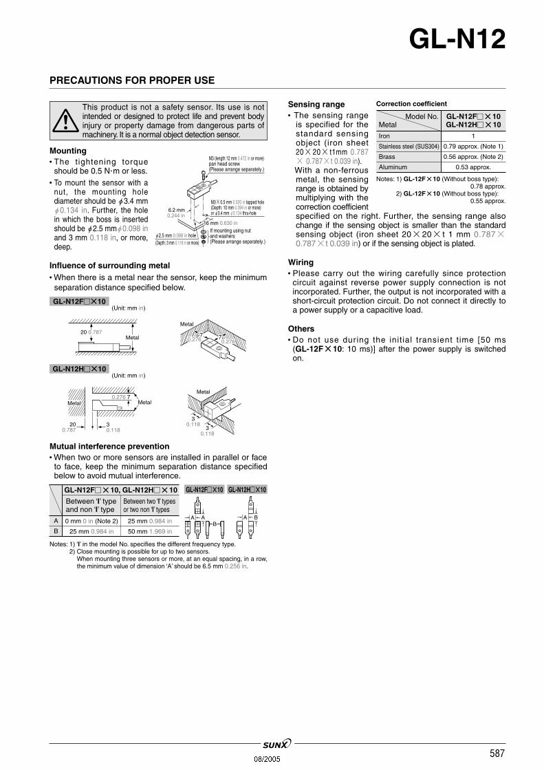
Sensing range• The sensing range
is specified for thestandard sensingobject (iron sheet2020 t1mm 0.787 0.787t 0.039 in).With a non-ferrousmetal, the sensingrange is obtained bymultiplying with thecorrection coefficientspecified on the right. Further, the sensing range alsochange if the sensing object is smaller than the standardsensing object (iron sheet 2020t 1 mm 0.7870.787t 0.039 in) or if the sensing object is plated.
Wiring• Please carry out the wiring carefully since protectioncircuit against reverse power supply connection is notincorporated. Further, the output is not incorporated with ashort-circuit protection circuit. Do not connect it directly toa power supply or a capacitive load.
Others• Do not use dur ing the init ial transient t ime [50 ms
(GL-12F10: 10 ms)] after the power supply is switchedon.
Model No.Metal
GL-N12F10GL-N12H10
Iron
Stainless steel (SUS304)
Brass
Aluminum
1
0.79 approx. (Note 1)
0.56 approx. (Note 2)
0.53 approx.
Mounting• The tightening torque
should be 0.5 Nm or less.• To mount the sensor with a
nut, the mounting holediameter should be "3.4 mm"0.134 in. Further, the holein which the boss is insertedshould be "2.5 mm"0.098 inand 3 mm 0.118 in, or more,deep.
Influence of surrounding metal• When there is a metal near the sensor, keep the minimumseparation distance specified below.
BAB
AA
GL-N12F10, GL-N12H10
Between ‘I’ typeand non ‘I’ type
Between two ‘I’ typesor two non ‘I’ types
A
B
0 mm 0 in (Note 2) 25 mm 0.984 in
25 mm 0.984 in 50 mm 1.969 in
30.118
30.118
Metal
30.118
200.787
0.276 7MetalMetal
Metal
7 70.276 0.276
20 0.787Metal
PRECAUTIONS FOR PROPER USE
This product is not a safety sensor. Its use is notintended or designed to protect life and prevent bodyinjury or property damage from dangerous parts ofmachinery. It is a normal object detection sensor.
GL-N12F10(Unit: mm in)
GL-N12H10(Unit: mm in)
Mutual interference prevention• When two or more sensors are installed in parallel or faceto face, keep the minimum separation distance specifiedbelow to avoid mutual interference.
GL-N12F10 GL-N12H10
Notes: 1) ‘I’ in the model No. specifies the different frequency type.2) Close mounting is possible for up to two sensors.
When mounting three sensors or more, at an equal spacing, in a row,the minimum value of dimension ‘A’ should be 6.5 mm 0.256 in.
Notes: 1) GL-12F10 (Without boss type):0.78 approx.
Notes: 2) GL-12F10 (Without boss type):0.55 approx.
Correction coefficient
M3 (length 12 mm 0.472 in or more)pan head screw(Please arrange separately.)
M30.5 mm 0.020 in tapped hole(Depth: 10 mm 0.394 in or more)or "3.4 mm "0.134 thru-hole
If mounting using nut and washers (Please arrange separately.)
"2.5 mm 0.098 in hole(Depth: 3 mm 0.118 in or more)
GL-12F
16 mm 0.630 in
6.2 mm0.244 in
588
GL-N12
22.20.874 27.4
1.079 32.21.268
G L - 1 2 F
7.10.280 6.2
0.2443
0.1181.150.045
2.90.114
11.60.457
11.20.441
120.472
Operation indicator(Red)
Sensingdirection
6.20.244
"3 "0.118 cable, 1 m 3.281 ft long
"3.2 "0.126 mounting hole
"6 "0.236 screw seat, 1.4 0.055 deep
5.80.2287.5
0.295
GL-N12F
6.20.244
"3 "0.118 cable, 1 m 3.281 ft long
"3.2 "0.126 mounting hole
"6 "0.236 screw seat,1.4 0.055 deep
5.80.2287.5
0.295
2.90.114
160.630
6.20.244
7.10.280
1.50.059
Operation indicator(Orange)
"2.3"0.091
120.47211.20.441
11.60.457
22.20.874 27.4
1.079 32.21.268
Sensing direction
160.630
20.079
20.079
t 0.4t 0.016
20.80.819
(13.05)(0.514)
2.40.094
50.197
(16)(0.630)(21.2)
(0.835)
"3.2 "0.126 hole
Center of sensing
"2.5 "0.098 hole,3 0.118 or more deep
M30.5 tapped hole,10 0.394 or more deep
3 0.118
0.30.012
8.50.335
22.2 0.874
120.472
2.90.114
27.4 1.07932.21.268
9.10.358
130.512
6.20.244
130.512
5.80.228
7.50.295
160.630
"2.3"0.091
7.30.287
1.50.059
GL
-N12
H
"3 "0.118 cable,1 m 3.281 ft long
"3.2 "0.126 mounting hole
"6 "0.236 screw seat,1.4 0.055 deep
Operation indicator(Orange)
Sensing direction
Mounting hole dimensions
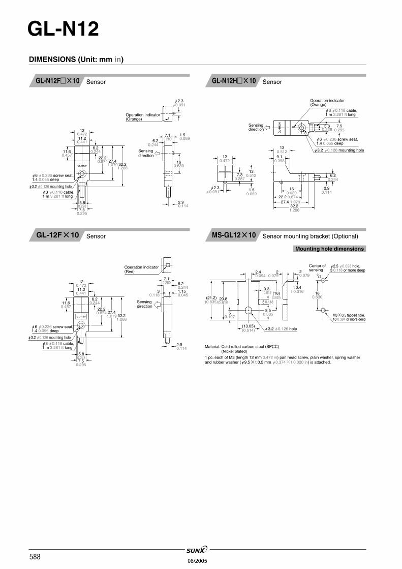
DIMENSIONS (Unit: mm in)
SensorGL-N12F10 SensorGL-N12H10
SensorGL-12F10 Sensor mounting bracket (Optional)MS-GL1210
Material: Cold rolled carbon steel (SPCC) Material: (Nickel plated)
1 pc. each of M3 (length 12 mm 0.472 in) pan head screw, plain washer, spring washerand rubber washer ("9.5t 0.5 mm "0.374t 0.020 in) is attached.