pneumercator series instruction... · instruction manual model lde 700 model e 700-1 (revised july...
TRANSCRIPT

Digital Tank Monitoring And Leak Detector Systems
© COPYRIGHT 2017 PNEUMERCATOR CO. 1785 EXPRESSWAY DRIVE NORTH, HAUPPAUGE, NY 11788
(631) 293-8450 Phone (631) 293-8533 Fax
(800) 209-7858 Product Support http://www.pneumercator.com
PNEUMERCATORLiquid Level Control Systems
INSTRUCTION MANUAL
MODEL LDE 700 MODEL E 700-1
(Revised July 9, 2017)


PNEUMERCATOR CO., INC. LDE 700 and E 700-1 System
Operation and Installation Manual
NOTICE: PNEUMERCATOR CO., INC. reserves the right to make improvements to the product described in these instructions at any time and with no notice. WARNING: This equipment generates, uses, and can radiate radio frequency energy and if not installed and used in accordance with the instruction manual, may cause interference to radio communications. It has been tested and found to comply with the limits for a Class A computing device pursuant to Subpart B of Part 15 of FCC Rules, which are designed to provide reasonable protection against such interference when operated in a commercial environment. Operation of this equipment in a residential area is likely to cause interference in which case the user at his own expense will be required to take whatever measures may be required to correct the interference. IMPORTANT: Installation of this equipment must be in accordance with these instructions as adopted from the following codes:
ISA RP12.6, "Installation of Intrinsically Safe Instrument Systems in Class I Hazardous Locations".
NFPA 70, "National Electrical Code". Alteration, modification or replacement with non-factory components could impair the intrinsic safety of this equipment.

PNEUMERCATOR CO., INC. LDE 700 and E 700-1 System
Operation and Installation Manual
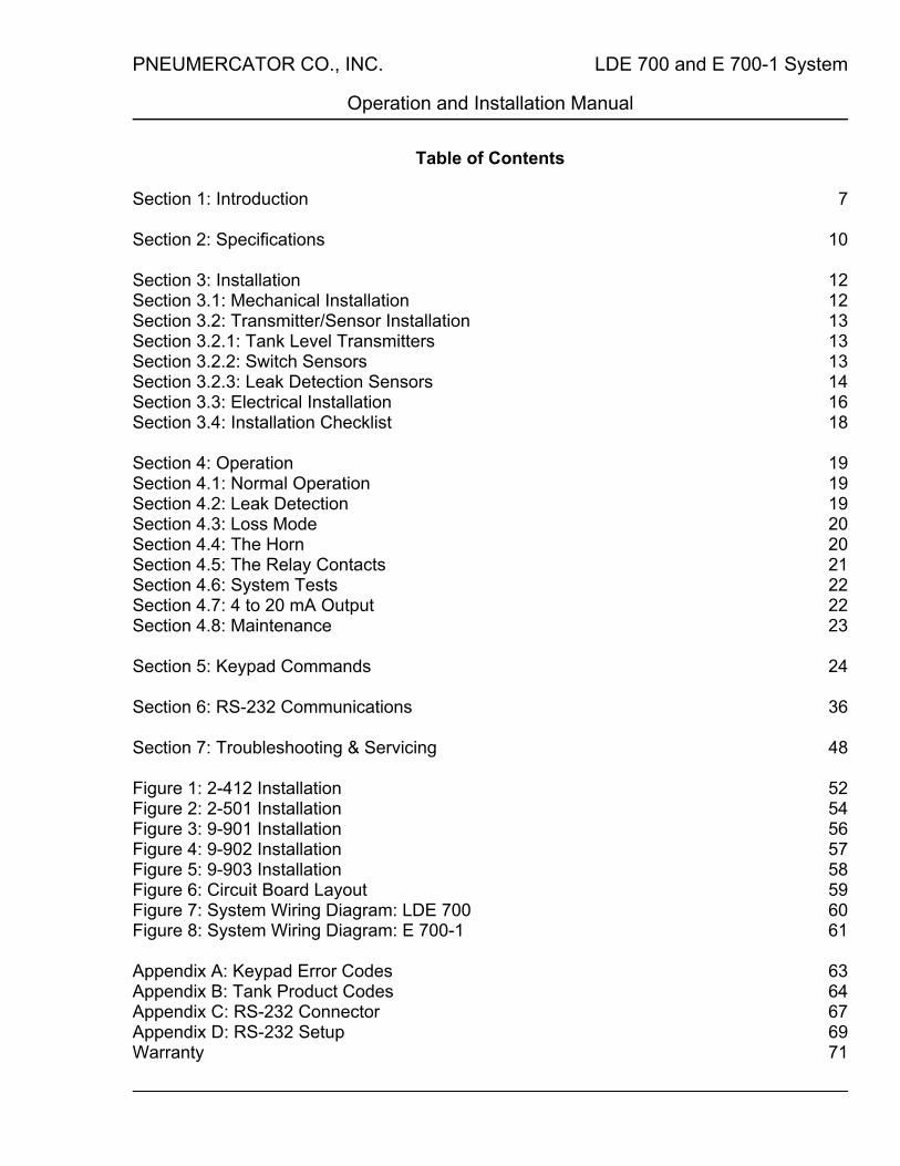
Table of Contents Section 1: Introduction 7 Section 2: Specifications 10 Section 3: Installation 12 Section 3.1: Mechanical Installation 12 Section 3.2: Transmitter/Sensor Installation 13 Section 3.2.1: Tank Level Transmitters 13 Section 3.2.2: Switch Sensors 13 Section 3.2.3: Leak Detection Sensors 14 Section 3.3: Electrical Installation 16 Section 3.4: Installation Checklist 18 Section 4: Operation 19 Section 4.1: Normal Operation 19 Section 4.2: Leak Detection 19 Section 4.3: Loss Mode 20 Section 4.4: The Horn 20 Section 4.5: The Relay Contacts 21 Section 4.6: System Tests 22 Section 4.7: 4 to 20 mA Output 22 Section 4.8: Maintenance 23 Section 5: Keypad Commands 24 Section 6: RS-232 Communications 36 Section 7: Troubleshooting & Servicing 48 Figure 1: 2-412 Installation 52 Figure 2: 2-501 Installation 54 Figure 3: 9-901 Installation 56 Figure 4: 9-902 Installation 57 Figure 5: 9-903 Installation 58 Figure 6: Circuit Board Layout 59 Figure 7: System Wiring Diagram: LDE 700 60 Figure 8: System Wiring Diagram: E 700-1 61 Appendix A: Keypad Error Codes 63 Appendix B: Tank Product Codes 64 Appendix C: RS-232 Connector 67 Appendix D: RS-232 Setup 69 Warranty 71


PNEUMERCATOR CO., INC. LDE 700 and E 700-1 System
Operation and Installation Manual
Page 7 of 72
Section 1: Introduction The PNEUMERCATOR LDE 700 and E 700-1 are advanced inventory
management and control systems. Drawing upon PNEUMERCATOR's more than 100 years of experience in liquid level controls and measurement systems, the LDE 700 and E 700-1 are designed to help simplify the inventory process, and to be extremely easy to operate.
These 16-bit microprocessor controlled systems continuously monitor the level
of product in a storage tank. The product level is available on the daylight visible display in units of either inches of product height (to the nearest hundredth of an inch), or in gallons. The product level and tank volume display is directly selectable from the Inch/Gallon switch.
The LDE 700 and E 700-1 easily accommodate different sizes of underground
and aboveground storage tanks, and are suitable for all types of fluids. Some of the fluids that are suitable for monitoring with the LDE 700 and E 700-1 are petroleum products, waste oil, conductive fluids, water, alcohols, solvents, lubricants, and corrosive chemicals. The gauges offer conversion of level to volume preprogrammed to match the geometry of the storage tank used. PNEUMERCATOR's many years of experience help guarantee an accurate conversion of height to gallons for all types and configurations of storage tanks.
The gauges provide audible, visible and (optional) printed outputs for high level
(overfill) and low level alarms, and 2 switch input alarms. Alarms are provided for loss detection. The LDE 700 also provides 2 channels of precision leak detection. Visible alarms are continuously on until the conditions are corrected. The audible alarm may be silenced for a particular condition by pressing the RESET pushbutton on the front panel and may be programmed from the integral keypad to automatically shut off after a specified period of time. The audible alarm may be disabled for all conditions, by using a keypad command in PROGRAMMING mode.
The gauges have 4 relays with dry contacts that will activate on
keypad-programmed conditions. The relay contacts are available at the terminal block as 1 Form C contacts that may be programmed for normally energized or normally deenergized states. The relay contacts are rated at 5 amps at 120 VAC.
Printed hardcopy inventory reports of product level and volume in the tank may
be requested at any time by pressing the PRINT pushbutton on the front panel if the optional printer is present.
PNEUMERCATOR CO., INC. LDE 700 and E 700-1 System
Operation and Installation Manual
Page 8 of 72
The systems feature self-diagnostics that test the audible alarm, visual alarms, clock, relay operation, and data storage memory. These tests are available from the keypad, and help to ensure reliable and trouble-free operation of the LDE 700 and E 700-1.
Setup parameters for the storage tank and for the system as a whole may be
printed at any time by a keypad command. This allows for hardcopy verifications and records of the conditions that the system is operating under.
Variations in tank installations, fitting tolerances, and tank tilts may be
compensated for by entering an installation offset adjustment. This allows the system to maintain maximum accuracy in its measurements.
The LDE 700 can take inputs from 2 leak detection sensors designed to monitor
collection sumps and the annular spaces of double wall tanks for leakage of hydrocarbons. The system provides individual indications for detection of air, water, and hydrocarbons. Detection of air is indicated by a Green light. Detection of hydrocarbons is indicated by a Red light. Detection of water is indicated by an Amber light. The leak detection capabilities meet EPA requirements for annual testing and monthly monitoring.
The LDE 700 will retain memory of a hydrocarbon or water alarm even if the
alarm condition later disappears. The alarm memory is battery backed up, so the memory will remain in the event of a power failure. The alarm memory may be cleared by a keypad command.
The adjustable volume system horn will sound an audible alarm while the
selected alarm conditions are present. Audible alarm silencing may be done by manually by pressing the RESET button on the cover of the console, or may be automatically timed for a selectable automatic time delay reset. Time delay periods of 1 to 7 minutes are available. Relay outputs may be programmed to actuate on selected conditions and may be programmed to shut off after time delays of from 1 to 15 minutes.
Sensors may be tested and calibrated by keypad programming. The switch
inputs may be programmed to accept normally open or normally closed mechanical contacts. The LDE 700 can be programmed to accept switch inputs at one or both leak detection inputs. Sensors for both sump and annular space detection may be mixed in a system with no limitations.

PNEUMERCATOR CO., INC. LDE 700 and E 700-1 System
Operation and Installation Manual
Page 9 of 72
The system alarm console may be mounted in any non-hazardous area where it can be provided with 120 VAC ±10% at 60 Hz. The standard enclosure is NEMA 1 with a NEMA 4 console optionally available.
The system level transmitters and sensors are designed for intrinsically safe
operation in Class I, Division 1, Group A, B, C, D areas. The level transmitters may be separated from the console by 3 wire #18 AWG runs of up to 5000 feet. Leak sensors may be separated from the console by 3 wire #18 AWG runs of up to 1000 feet. Switch sensors may be separated from the console by 2 wire #18 AWG runs of up to 5000 feet.
The system is designed to provide safe and reliable operation when installed
as instructed in the Installation section of this manual. All requirements of the National Electrical Code (NEC) as well as local electrical and fire codes should be followed in the installation procedures. It is recommended that the user read and understand ANSI/ISA RP12.6, "Installation of Intrinsically Safe Instrument Systems in Class I Hazardous Locations".
If additional information is needed concerning equipment selection, system
planning, installation, operation, servicing, or maintenance, please contact:
PNEUMERCATOR CO., INC. 1785 Expressway Drive North Hauppauge, New York, 11788
Phone (631) 293-8450 Fax (631) 293-8533
http://www.pneumercator.com

PNEUMERCATOR CO., INC. LDE 700 and E 700-1 System
Operation and Installation Manual
Page 10 of 72
Section 2: Specifications Power - 120 VAC ± 10%, 60 hertz, 48 Watts, MOV surge protection, undervoltage detection and protection. Fuse - 3 A.G. SLO-BLO, 1/4 Amp, 250 VAC or equivalent. Operating Temperature - -40º F to 122º F (-40º C to 50º C). Enclosure - NEMA 1 standard, NEMA 4 optional. Installation - Wall mount. Calibrations - Alarm points and programming set by keypad & maintained for 10-year data retention on power failure. Gauging Resolution - 0.1% of tank height. Gauging Accuracy - ±0.12% of tank height or ±1/8" w/2-412 or ±1/4" w/2-501, whichever is greatest. Gauging Repeatability - ±0.1% of tank height. Displays - Red, 0.8 inch high, seven segment displays. Inch/Gallon, Loss mode and Data recall switches. Alarm Indications - High (overfill) and Low level red LEDs, 2 Switch indication red LEDs. Horn - Min. 85 dB at 3 meters on axis, manual horn reset (silence) pushbutton, automatically timed horn silence. Relay Outputs - 4 SPDT dry relay contacts, rated at 5 Amps at 120 VAC, individually keypad programmable for actuating condition(s) and normally energized or normally deenergized. Clock - The clock maintains the time and date and year for (optional) printer functions. It automatically compensates for Leap Year corrections and Daylight Savings Time. The time is maintained with an accuracy of ±11 sec/day. 10 year data retention on power failure. Level Transmitter - Standard: 2-412 or 2-501. Intrinsically safe for Class I, Division 1, Groups A, B, C, D, 5 VDC @45 mA. Optionally from isolated self-powered 4 to 20 mA transducer capable of driving 500 (not intrinsically safe). Switch Inputs - 2 from any mechanical switch input. Intrinsically safe for Class I, Division 1, Groups A, B, C, D, 5 VDC @25 mA. Individually keypad programmable for normally open or normally closed switch inputs.

PNEUMERCATOR CO., INC. LDE 700 and E 700-1 System
Operation and Installation Manual
Page 11 of 72
Output Signals - Optional RS-232 (standard with LDE 700). Optional 4 to 20 mA non-isolated output, 500 max. load, keypad programmable for percent of height or volume. Optional 20-column dot matrix printer. Leak Detection Sensors (LDE 700) - 2 from 9-901, 9-902, and 9-903 sensors. Intrinsically safe for Class I, Division 1, Groups A, B, C, D, 5 VDC @45 mA. Can be individually programmed from keypad to alternately accept normally open or normally closed mechanical switch inputs. Leak Detection Testing (LDE 700) - Meets EPA requirements for annual testing and monthly monitoring. Hydrocarbon Detection (LDE 700) - Products that are to be detected must be nonconductive fluids having a dielectric value of between 2 and 12. 9-901: 0.33”, 100% pfd, 0% pfa @ 0.1 gph. 9-902: 0.35”, 100% pfd, 0% pfa @ 0.1 gph. 9-903: 0.68”, 100% pfd, 0% pfa @ 0.1 gph. Leak Detection Response Time (LDE 700) - Less than 1 second for detection, 1 minute for alarm latch. Leak Detection Indicators (LDE 700) - Red LED indicates oil detection. Amber LED indicates water detection. Green LED indicates air (normal condition). Level Transmitter/Sensor Operating Temperature - 9-901, 9-902, 9-903 Sensors: -40 ºF to 130 ºF (-40 ºC to 55 ºC). 2-412, 2-501 Level Transmitter: -20 ºF to 180 ºF (-29 ºC to 82 ºC). LS600 Switch Sensors: -20 ºF to 180 ºF (-29 ºC to 82 ºC). LS600LD Leak Sensors: -40 ºF to 160 ºF (-40 ºC to 71 ºC). Level Transmitter/Sensor Operating Pressure - 9-901, 9-902, 9-903 Sensors: ambient (vented). 2-412 Level Transmitter: to 50 psi. 2-501 Level Transmitter: to 15 psi. LS600 Switch Sensors: to 150 psi. LS600LD Leak Sensors: to 100 psi. Level Transmitter/Sensor Cable - 2-412, 2-501, 9-901, 9-902, 9-903: Standard 3 conductor #18 AWG, 2-412 and 2-501 up to 5000 feet. 9-900 sensors up to 1000 feet. Switch sensors: Standard 2 conductor #18 AWG, up to 5000 feet.

PNEUMERCATOR CO., INC. LDE 700 and E 700-1 System
Operation and Installation Manual
Page 12 of 72
Section 3: Installation
NOTE: INSTALLATION MUST BE DONE BY QUALIFIED PERSONNEL, FAMILIAR WITH LOCAL WIRING CODES AND EXPLOSION HAZARD ELECTRICAL SAFETY PRACTICES.
Section 3.1: --Mechanical Installation
The LDE 700 or E 700-1 console is a NEMA 1 enclosure intended for indoor
installation. An optional NEMA 4 enclosure intended for indoor or outdoor installation is available and offers protection against splashing water, seepage of water, falling of hose directed water, and severe external condensation. The NEMA 4 enclosure is also sleet resistant. Either enclosure has mounting flanges that allow permanent fastening to walls, panels, etc.
The console should be located in an area that is easily accessible to the
personnel responsible for operating the system. This is to allow easy maintenance access, and access to the console for operation and testing. The console must be located in a non-hazardous area, as close as possible to the demarcation point of the hazardous area, with available 120 VAC power brought to the console through a dedicated metal wiring conduit. The metal conduits for the level transmitter, sensors and power should be weathertight. Bottom entrance holes are provided for 1/2" NPT pipe or rigid metal conduit, with the level transmitter and sensors entering on the bottom left and power entering on the bottom right.
Consult the local electrical codes for specific requirements.

PNEUMERCATOR CO., INC. LDE 700 and E 700-1 System
Operation and Installation Manual
Page 13 of 72
Section 3.2 Level Transmitter/Sensor Installation
Section 3.2.1 Tank Level Transmitter There are two tank-gauging level transmitters available for the LDE 700 and
E 700-1. The model 2-412 is designed for installation in 4” minimum tank openings. The model 2-501 is designed for installation in 2” minimum tank openings and is designed for use with heavy viscous fluids like #6 oil. Self-powered transducers that provide an isolated 4 to 20 mA output may be used for tank gauging if the LDE 700 or E 700-1 are ordered from the factory with this option. If a 4 to 20 mA output transducer is used, two (2) 18 AWG wires are required.
Three (3) 18 AWG wires are required for the model 2-412 and model 2-501
level transmitters. The wiring should be run through NEMA 4 or better junction boxes and 1/2" weatherproof liquid tight metal conduit. The metal conduit and junction boxes should be sealed against entry of water. If required, vapor seals may be installed to prevent gas vapors from propagating back to the console. The transmitter wiring to the console should be run in a dedicated metal wiring conduit. No non-intrinsically safe wires should be in the same conduit unless a metal barrier is provided.
The tank level transmitter is wired to TB2 on the circuit board. The Red wire is
connected to position 1, the White wire is connected to position 2 and the Black wire is connected to position 3. If a 2-wire transducer is used, the (+) wire is connected to position 2 and the (-) wire is connected to position 3. Position 1 is not used with a 2-wire transducer.
The wiring and terminal block (TB2) are intrinsically safe and are physically
separated from the AC power and relay contact and 4 to 20 wiring and terminal blocks on the right side (TB5, 6, 7). This separation must be maintained.
See Figure 7, System Wiring Diagram: LDE 700, Page 60. See Figure 8, System Wiring Diagram: E 700-1, Page 61. 2-412 Installation (see Figure 1, Pages 52, 53) 2-501 Installation (see Figure 2, Pages 54, 55)
Section 3.2.2: Switch Sensors
PNEUMERCATOR makes a number of different LS600 series switch sensors
that may be used with the E 700-1 and LDE 700. See the appropriate LS600 bulletins for details on these. Any other mechanical switch closure may also be used as switch inputs. The LDE 700 may also be programmed from the keypad to accept switch

PNEUMERCATOR CO., INC. LDE 700 and E 700-1 System
Operation and Installation Manual
Page 14 of 72
inputs at one or both LEAK inputs. If this feature is used, the two (2) wires of the switch are connected to TB4 positions 1 and 2 if LEAK input 1 is programmed as a switch and to TB4 positions 4 and 5 if LEAK input 2 is programmed as a switch.
Two (2) 18 AWG wires are required for each switch sensor. The wiring should
be run through NEMA 4 or better junction boxes and 1/2" weatherproof liquid tight metal conduit. The metal conduit and junction boxes should be sealed against entry of water. If required, vapor seals may be installed to prevent gas vapors from propagating back to the console. The switch sensor wiring to the console should be run in a dedicated metal wiring conduit. No non-intrinsically safe wires should be in the same conduit unless a metal barrier is provided.
The switch sensors are wired to TB3 on the circuit board. The first switch sensor
is wired to positions 1 and 2, and if there is a second switch sensor it is wired to positions 3 and 4.
The wiring and terminal block (TB3) are intrinsically safe and are physically
separated from the AC power and relay contact and 4 to 20 wiring and terminal blocks on the right side (TB5, 6, 7). This separation must be maintained.
See Figure 7, System Wiring Diagram: LDE 700, Page 60. See Figure 8, System Wiring Diagram: E 700-1, Page 61.
Section 3.2.3: Leak Detection Sensors There are three leak detection sensors available for the LDE 700. The model
9-901 is designed for installation in a horizontal position in the annular space of F.R.P. double wall tanks. The model 9-902 and 9-903 are designed for installation in a vertical position in collection sumps, monitoring pipes and steel double-wall tank sumps.
Three (3) 18 AWG wires are required for each sensor. The wiring should be run
through NEMA 4 or better junction boxes and 1/2" weatherproof liquid tight metal conduit. The metal conduit and junction boxes should be sealed against entry of water. If required, vapor seals may be installed to prevent gas vapors from propagating back to the console. The sensor wiring to the console should be run in a dedicated metal wiring conduit. No non-intrinsically safe wires should be in the same conduit unless a metal barrier is provided.
The sensors are wired to TB4 on the circuit board. The first sensor is wired to
positions 1, 2 and 3, and if there is a second sensor it is wired to positions 4, 5 and 6. The Red wire is connected to position 1, the White wire is connected to position 2,

PNEUMERCATOR CO., INC. LDE 700 and E 700-1 System
Operation and Installation Manual
Page 15 of 72
and the Black wire is connected to position 3. If there is a second sensor, the Red wire is connected to position 4, the White wire is connected to position 5, and the Black wire is connected to position 6.
The wiring and terminal block (TB4) are intrinsically safe and are physically
separated from the AC power and relay contact and 4 to 20 wiring and terminal blocks on the right side (TB5, 6, 7). This separation must be maintained.
9-901 Installation (see Figure 3, Page 56 for drawing)
Tank size Measurement length 4’ 81"
6' 118" 8’ 149.5" 10’ 193.5" 12’ 222"
1. Use the chart above to determine the cable measurement length for the size of the tank being monitored. 2. Unroll the sensor/cable assembly and measure from the sensor bottom to the cable measurement length. Mark the cable at that point. 3. Feed the cable through the bottom of the mounting bushing and cord connector until the mark on the cable is even with the top of the mounting bushing. Insert the sensor and cable through the 2” NPT opening and into the annular space. 4. Screw in the mounting bushing and connector. 5. Tighten the connector with the cable mark in the correct position. 6. Wire the sensor cable end to three 18 AWG wires in a NEMA 4 or better junction box or in an optional splice kit, part number 10585-3. 9-902 Installation (see Figure 4, Page 57 for drawing) 1. Measure the distance from the top of the 2” opening to the bottom of the area being monitored. This is the mounting height. 2. Add 2 and 3/16 inches to this dimension to find the cable length measurement.

PNEUMERCATOR CO., INC. LDE 700 and E 700-1 System
Operation and Installation Manual
Page 16 of 72
3. Unroll the sensor/cable assembly and measure from the sensor bottom to the cable measurement length. Mark the cable at that point. 4. Feed the cable through the bottom of the mounting bushing and cord connector until the mark on the cable is even with the top of the mounting bushing. Insert the sensor and cable through the 2" NPT opening. 5. Screw in the mounting bushing and connector. 6. Tighten the connector with the cable mark in the correct position. 7. Wire the sensor cable end to three 18 AWG wires in a NEMA 4 or better junction box or in an optional splice kit, part number 10585-3. 9-903 Installation (see Figure 5, Page 58 for drawing) 1. Measure the distance from the top of the opening to the bottom of the area being monitored. This is the mounting height. 2. If using the optional Pneumercator leak monitor tube assembly for Convault tanks (assembly #900379-1), add 1 inch to this dimension to find the cable length measurement. 3. Unroll the sensor/cable assembly and measure from the sensor bottom to the cable measurement length. Mark the cable at that point. 4. Feed the cable through the bottom of the tube cover and cord connector until the mark on the cable is visible. Insert the sensor and cable through the monitoring opening. 5. Screw the cord connector into the tube cover and place back on the tube. 6. Tighten the connector with the cable mark in the correct position. 7. Wire the sensor cable end to three 18 AWG wires in a NEMA 4 or better junction box or in an optional splice kit, part number 10585-3.
Section 3.3: Electrical Installation
WARNING: Do not connect 120 VAC or turn on 120 VAC until all other
connections have been made, all equipment has been installed, and final inspection has been completed.

PNEUMERCATOR CO., INC. LDE 700 and E 700-1 System
Operation and Installation Manual
Page 17 of 72
The LDE 700 or E 700-1 requires a power input of 120 VAC, ±10%, 60 Hz. The unit is fused with a 1/4 Amp, 3AG Slo-Blo fuse. Total power usage is less than 40 Watts. The power input is protected against common-mode power surges with a metal-oxide varistor (MOV). The power line for the alarm console should not share a breaker circuit with any motors, compressors, or other sources of power surges or voltage sags. The power wiring to the alarm console should be run in a dedicated metal wiring conduit. No other wires should be in the same conduit unless a metal barrier is provided. Three wires make up the power input to the LDE 700 or E 700-1: Black (hot), White (neutral) and Green (ground).
The A.C. power wires run to the terminal block labeled TB7, to positions 1, 2,
and 3. Position 1, labeled HI, is the hot lead. Position 2, labeled LO, is the neutral lead. Position 3, labeled GND, is the ground lead. The terminal blocks will accept wire sizes up to 14 AWG stranded wire. The wiring and terminal block on the left side (TB1, 2, 3, 4) are intrinsically safe and are physically separated from the AC power and relay contact and 4 to. 20 mA output wiring and terminal block on the right side (TB5, 6, 7). This separation must be maintained.
IMPORTANT
Connect a 12 AWG copper wire from the terminal block TB1 (labeled Earth
Ground) to a good earth ground. The ground connection must be within 1 OHM of true ground and must be made at only one point for the system to maintain intrinsic safety.
Properly dress all wires inside the wiring sections and securely clamp down the
enclosure door and tighten all conduit entrances to seal the system watertight. Install vapor seals in accordance with local codes for hazardous locations if applicable.

PNEUMERCATOR CO., INC. LDE 700 and E 700-1 System
Operation and Installation Manual
Page 18 of 72
Section 3.4: Installation Checklist Do not apply power to the unit until its installation has been checked and
found to be in accordance with the instructions in this manual; the National Electrical Code; federal, state and local codes; and other applicable safety codes. 1. Check to be sure that the level transmitter and sensor wires are contained in a dedicated, separate metal wiring conduit. 2. Verify that all conduits enter the alarm console through the proper conduit openings on the bottom of the console. 3. Verify that a 12 AWG copper wire has been connected between TB1 (labeled Earth Ground) and a good earth ground. 4. Verify that the power supply terminals are correctly wired. 5. Verify that system power is properly wired to a separate, dedicated circuit breaker. 6. Verify that the level transmitter and all sensors have been properly wired with color-coded or marked 18 AWG wires and that the proper color-coding or marking has been maintained throughout the wiring runs. 7. Verify that all wiring splices are waterproof. Pneumercator part #10585-3 (splice kit) or equivalent or NEMA 4 or better junction box should be used for all wiring splices. 8. Securely clamp down the enclosure door.

PNEUMERCATOR CO., INC. LDE 700 and E 700-1 System
Operation and Installation Manual
Page 19 of 72
Section 4: Operation IMPORTANT: Before operating the system, make sure that all items on the installation checklist in the Installation section of this manual have been checked out and complied with. Circuit Board layout (see Figure 6, Page 59 for drawing)
Section 4.1: Normal Operation
In normal operation there will be no alarm lights on and the horn will be silent.
The display will show the level of product in the storage tank in either gallons of volume or inches of height. The display of gallons or inches is controlled by the position of S1 on the circuit board (labeled GALLONS on the left and INCHES on the right). The Loss mode switch (S2) should be toward the left, in the NORMAL position. LDE 700 units should have Green light(s) on for installed leak detection sensors.
The system will continuously monitor the level of product in the tank and will
display in the selected mode. Alarms will actuate the appropriate light and relay and the horn (if the relay or horn is programmed for that alarm). Alarm conditions and levels may be individually programmed from the keypad or the RS-232 communications port.
Section 4.2: Leak Detection
Leak detection testing with 9-901, 9-902 and 9-903 (LDE 700 only) meets EPA
requirements for annual testing and monthly monitoring. These sensors are intrinsically safe for use in Class I, Division 1, Groups A, B, C, D areas. Products that are to be detected must be nonconductive fluids having a dielectric value of between 2 and 12.
Leak detection response time (LDE 700 only) is less than 1 second for detection
of product or water at the threshold level. The system will latch a leak detection alarm after 1 minute of continuous detection. This is to ensure that an alarm state is not ignored or bypassed. A leak detection alarm latch may be cleared by keypad or RS-232 communications port command or by recalibrating the leak input channels.
Calibration may be done either from the keypad or the RS-232 communications
port. The sensors must be clean and dry and in air. If the sensors are in oil or water, clean and dry them off before calibrating. Leak Detection Indicators (LDE 700 only) Red LED indicates oil detection.

PNEUMERCATOR CO., INC. LDE 700 and E 700-1 System
Operation and Installation Manual
Page 20 of 72
Amber LED indicates water detection. Green LED indicates air (normal condition).
Either or both leak input channels may be programmed as extra switch inputs
from the keypad or the RS-232 communications port. Using a leak channel as a switch input disables it for use as a leak input channel. Switches and leak sensors may not be mixed on the same input.
Section 4.3: Loss Mode
Loss (Theft) mode may be entered by toggling S2 on the circuit board to the
THEFT position (right). When Loss mode is entered, the system records the product level in battery-backed memory. Any removal of 1% of the recorded product level will trigger the Theft alarm and cause the display to flash. The original product level before the loss may be displayed by pressing the Data Recall momentary pushbutton switch on the circuit board. Releasing the Data Recall pushbutton will resume display of the current product level. Toggling S2 to the NORMAL position (left) will exit Loss mode.
This mode is intended to detect only gross unauthorized removal of product. It
is not intended to comply with EPA or other regulations in regard to leak detection.
Section 4.4: The Horn The volume of the audible alarm may be controlled by rotating the louver on the
face of the horn. The maximum volume of the horn is a minimum of 85 dB at two feet, and the loudness may be varied by about 40 dB.
The horn may be reset (silenced) after detection of a warning condition by
pressing the RESET button on the cover of the system console. This will silence the horn, but the condition light will remain on.
The system is normally set at the factory to only actuate the horn on High
(overfill), Low level, Switch 1, and Switch 2 alarms and Hydrocarbon detection (LDE 700). These conditions may be changed by programming the horn with the keypad or RS-232 communications port. The horn may also be programmed to be disabled.
The system is normally set at the factory to disable the automatic horn reset
function. This setup will let the horn sound on detection of the programmed alarm conditions until it is manually silenced by pressing the RESET button on the system console cover. The automatic horn reset function may be programmed to operate after a period of from 1 to 7 minutes with the keypad or the RS-232 communications port.

PNEUMERCATOR CO., INC. LDE 700 and E 700-1 System
Operation and Installation Manual
Page 21 of 72
The horn has a delay built-in, so that the same repeating alarm condition will
not reenergize the audible alarm before 10 minutes. Other alarm conditions will activate the horn regardless of the delay state for a different condition.
Section 4.5: The Relay Contacts
There are 4 relays in the system that provides SPDT 1 Form C dry relay
contacts. The terminal block relay contacts for the relays are brought out to TB6, and are labeled as outputs 1 through 4, Normally Closed (NC), Common (C) and Normally Open (NO) positions. These contacts are rated to 5 amps at 120 VAC. Wire sizes up to 14 AWG stranded wire may be used to connect to these relay contact outputs. If the load on the relay contacts exceeds this rating, then the relay should be used to actuate an external power relay of appropriate rating (not supplied by PNEUMERCATOR).
The default programming for the relays is: Relay 1 - actuate on High (overfill) alarm. Relay 2 - actuate on Low level alarm. Relay 3 - E 700-1 : actuate on Switch 1 alarm.
LDE 700 : actuate on Switch 1,2 alarms. Relay 4 - E 700-1 : actuate on Switch 2 alarm.
LDE 700 : actuate on Hydrocarbon alarm. These conditions may be changed by programming the horn with the keypad
or RS-232 communications port. In the default programming, the relays are normally deenergized in a nonalarm
state, there is no continuity between the Normally Open (NO) and Common (C) contacts and there is continuity between the Normally Closed (NC) and Common (C) contacts. When a programmed alarm condition is detected the relay actuates. This gives continuity between the Normally Open (NO) and Common (C) contacts, and breaks continuity between the Normally Closed (NC) and Common (C) contacts. The relays may be individually programmed to be in a normally energized state, which will toggle the states of the contacts. In this case, the relay(s) will deenergize on a programmed alarm condition. This may also be used to give indication of a power failure, since the relay will deenergize when the power is off.
The system is normally set at the factory to actuate the relays for the duration of an alarm condition. The relays may be individually programmed to deactivate after a preselected time period of from 1 to 15 minutes. The relays may also be individually programmed to have a delay of 5 minutes from the time an alarm is detected and maintained until relay actuation. All relay programming may be done from the keypad or from the RS-232 communication port.

PNEUMERCATOR CO., INC. LDE 700 and E 700-1 System
Operation and Installation Manual
Page 22 of 72
Section 4.6: System Tests
The system LEDs, horn, RAM (memory), clock and relays may be tested from
the keypad. The LEDs test will light all the LEDs on the cover until a keypress cancels the test and returns to normal mode. The horn test will sound the horn until a keypress cancels the test and returns to normal mode. This test may be left running to test operation of the autosilence mode. The operation of the RESET pushbutton may also be verified during this test. The RAM and clock tests will return to normal mode automatically unless a fault is detected. In that case, an error code will be displayed. The relay test will first activate the relays and then deactivate them after a keypress.
Section 4.7: 4 to 20 mA Output
The optional 4 to 20 mA output can be used to feed a current output to process
control equipment, energy management systems or chart recorders. The normal 4 to 20 mA module has a non-isolated output and can drive loads with a maximum impedance of 500. The minus (-) line of the output should not be connected to ground either directly or through a resistance. If the equipment that will receive the signal has a grounded input, then the output of the 4 to 20 mA converter must be isolated, either by an inline isolation module or by ordering the system with a special isolated 4 to 20 mA converter.
The output will normally provide an output as a percentage of product volume.
It may be programmed to provide an output as a percentage of product height in the tank from the keypad or from the RS-232 communications port. 4 mA will always represent 0 gallons and 0" of product height. 20 mA will always represent full capacity of the tank in gallons or inches. The outputs are not necessarily the same between output modes due to the nonlinear geometry of many storage tanks. Because of gauging losses at the top and bottom of the storage tank, the outputs observed may not ever reach the 4 mA or 20 mA points.

PNEUMERCATOR CO., INC. LDE 700 and E 700-1 System
Operation and Installation Manual
Page 23 of 72
Section 4.8: Maintenance The time between maintenance periods is a variable that will depend upon the
environment in which the level transmitter, sensors and system console are operating. The console should be tested every six months by using the keypad self-diagnostic commands.
The leak detection sensors should be visually inspected for fouling or clogging
at least once a year. A fouled or clogged leak sensor can give false alarms. If the leak sensor is fouled or clogged, it should be cleaned with soap and water or a mild solvent, and unclogged with compressed air. After visual inspection, the leak sensors should be reinstalled, and recalibrated.
If an actual leak occurs, after corrective action is taken, the leak sensors should
be cleaned and inspected and recalibrated before reinstallation.

PNEUMERCATOR CO., INC. LDE 700 and E 700-1 System
Operation and Installation Manual
Page 24 of 72
Section 5: Keypad Command
Key Definitions
Key Meaning 0 0 1 1 2 2 3 3 4 4 5 5 6 6 7 7 8 8 9 9 A Null (reserved) B Backspace C Cancel D Dash (Minus Sign) E Enter F Function
How To Enter Keypad Commands
FUNCTION: The FUNCTION key, which is labeled ‘F', precedes all commands given
in PROGRAM mode. - (MINUS): The minus sign, which is labeled 'D' (for DASH), is used in the entry of
installation offset adjustments. BACKSPACE: The BACKSPACE key, which is labeled 'B', is used to correct an error
in key entry in PROGRAM mode. The BACKSPACE will erase the mistaken key entry and correct the display.
ENTER: The ENTER key, which is labeled 'E', is used to terminate ALL command
entries in PROGRAM mode. A command will not be performed until the ENTER key is pressed. Until the ENTER key is pressed, the command line can be edited with the BACKSPACE and CANCEL LINE keys.
CANCEL LINE: The CANCEL LINE key, which is labeled 'C', can be used to cancel a
command line at any time until the ENTER key is pressed.

PNEUMERCATOR CO., INC. LDE 700 and E 700-1 System
Operation and Installation Manual
Page 25 of 72
NULL: The NULL key, which is labeled 'A', has no defined use at the present time. Entry of the NULL key should be corrected by use of the BACKSPACE or CANCEL LINE keys.
**** Where braces { } are shown bracketing parameters in the commands, they are shown for reasons of clarity only, and must not be entered into the command line entered into the E 700-1 or LDE 700. ****
**** When PROGRAMMING mode is entered by pressing the FUNCTION key
on the keypad, the front panel display is cleared, and the function symbol is displayed. The function symbol is a box in the bottom right of the display window. As command numbers and parameters are entered, the characters displayed move left. Characters that scroll off the left end of the display are not lost, merely past the display window. They may be reshown when the backspace key is used. During PROGRAMMING mode all normal gauging and alarm functions are performed. If no key has been pressed for two minutes, PROGRAMMING mode is automatically canceled, and the normal display is resumed. ****

PNEUMERCATOR CO., INC. LDE 700 and E 700-1 System
Operation and Installation Manual
Page 26 of 72
Key Command Table - Keypad Initiated Commands Function Command Number Clock Display Time 00 Enter Time 01 Display Date 02 Enter Date 03 Display Weekday 04 Enter Weekday 05 Print Clock 06 Alarm Display High Alarm Setting 07 Print High Alarm Setting 08 Enter High Alarm Setting 09 Display Low Alarm Setting 10 Print Low Alarm Setting 11 Enter Low Alarm Setting 12 Tank Print Tank Parameters 13 Display Offset Adjustment 14 Print Offset Adjustment 15 Enter Offset Adjustment 16 Diagnostics Test LEDs 17 Test Horn 18 Test Ram (memory) 19 Test Clock 20 Test Relays 21 Test RS-232 Port 57 Note 3 Printer Enter Automatic Print Time 22 Print Automatic Print Times 23 Enter Product Code 24 Print Product Name 25 Clear Printer Buffer 26 RS-232 Display Baud Rate 27 Print Baud Rate 28 Enter Baud Rate 29

PNEUMERCATOR CO., INC. LDE 700 and E 700-1 System
Operation and Installation Manual
Page 27 of 72
System Print System Setup 30 Print Alarm Status 31 Program Horn 32 Program Horn Shutoff 33 Print Horn Setup 34 Program Relays 35 Program Relay Shutoff 36 Program Relay State 37 Program Relay Delay 38 Print Relay Setup 39 Program Switches 40 Print Switch Setup 41 Program Leak Detection 42 Calibrate Leak Detection 43 Clear Leak Detection Latch 44 Print Leak Detection Setup 45 Program 4 to 20 mA Output 46 Calibrate 4 to 20 mA Output 47 Print 4 to 20 mA Setup 48 Calibrate Zero 49 Calibrate Span 50 Warm Reset System 51 Cold Reset System 52 Test LEDs and Horn 53 Note 1 Enter Auto Answer Ring Count 54 Note 2 Display Auto Answer Setup 55 Note 2 Print Auto Answer Setup 56 Note 2 Test RS-232 Port 57 Note 3 Note 1: Available with software version 1.06 and greater Note 2: Available with software version 1.07 and greater Note 3: Available with software version 1.08 and greater

PNEUMERCATOR CO., INC. LDE 700 and E 700-1 System
Operation and Installation Manual
Page 28 of 72
Keypad Command Entry **** NOTE: All character positions shown in the command definition, except for
braces { }, must be entered, i.e. 'nnnnn' calls for the entry of 5 digits. Display Time (00): F 00 E
Displays time until any keypress or timeout. Enter Time (01): F 01 hh mm E
hh is the hours (in military time),i.e. 15 is 3 PM. mm is the minutes, i.e. 20 is 20 after the hour.
Display Date (02): F 02 E
Displays the date until any keypress or timeout. Enter Date (03): F 03 mm dd yy E
mm is the month, i.e. 04 is April. dd is the date, i.e. 03 is the third day of the month. yy is the year, i.e. 92 is 1992, 00 is 2000, 01 is 2001.
Display Weekday (04): F 04 E
Displays the day of the week until any keypress or timeout. Enter Weekday (05): F 05 d E
d is the day of the week. Sunday = 1. Monday = 2. Tuesday = 3. Wednesday = 4. Thursday = 5. Friday = 6. Saturday = 7.
Print Clock (06): F 06 E
Prints clock date and time settings. Display High Alarm Setting (07): F 07 E
Displays the level set for high alarm until any keypress or timeout. Print High Alarm Setting (08): F 08 E
Prints high (overfill) alarm setting. Enter High Alarm Setting (09): F 09 nnnnn E
nnnnn is the level to set the alarm (5 digits required). Leading zeroes are required, i.e. 6000 gallons must be entered as 06000.

PNEUMERCATOR CO., INC. LDE 700 and E 700-1 System
Operation and Installation Manual
Page 29 of 72
Display Low Alarm Setting (10): F 10 E Displays the level set for low alarm until any keypress or timeout.
Print Low Alarm Setting (11): F 11 E
Prints low alarm setting. Enter Low Alarm Setting (12): F 12 nnnnn E
nnnnn is the level to set the alarm (5 digits required). Leading zeroes are required, i.e. 600 gallons must be entered as 00600.
Print Tank Parameters (13): F 13 E
Prints the setup parameters for the tank. The parameters printed are: tank product name; high level and low level alarm settings; tank capacity; tank diameter; and installation offset for the tank. Display Offset Adjustment (14): F 14 E
Displays the level set for the offset adjustment until any keypress or timeout. Print Offset Adjustment (15): F 15 E
Prints the offset adjustment for the tank. Enter Offset Adjustment (16): F 16 {-}nnn E
nnn is the level to set the offset to (this level is entered in hundredths of an inch, i.e. 2 inches is entered as 200. The offset for a tank may range from -9.99 inches to +9.99 inches.
Leading zeroes are required, i.e. 0.50 inches of positive offset must be entered as 050.
If a negative offset is desired, it is preceded by a minus (-) sign. This is accomplished by pressing the key labeled 'D'. No sign is required or allowed for a positive offset.
The offset for the tank is derived as follows: 1.First remove any pressurized or vapor recovery tubes from the dipstick
measurement opening. These tubes can cause a reading to vary by as much as 3 inches depending upon the pressure in the tank.
2.Take a very careful dipstick reading with an accurate dipstick. Write down the reading.
3.Write down the fuel height in inches shown by the Gauge. 4.Subtract the Gauge reading from the dipstick reading
(Dipstick - Gauge = Difference) to get the Installation Offset and record it for reference. Test LEDs (17): F 17 E
Lights all the system LEDs, any keypress turns off the LEDs. Test Horn (18): F 18 E
Turns on the horn, any keypress turns off the horn.
PNEUMERCATOR CO., INC. LDE 700 and E 700-1 System
Operation and Installation Manual
Page 30 of 72
Test RAM (19): F 19 E Tests the scratchpad memory, if an error is found, an error code is displayed (error
code #4). If no error is found, no message is presented. Test Clock (20): F 20 E
Tests the clock, if an error is found, an error code is displayed (error code #2). If no error is found, no message is presented. Test Relays (21): F 21 E
Toggles the state of all the relays, any keypress toggles the relay states again and ends the test. Enter Automatic Print Time (22): F 22 n hh mm d E
n is the number of the automatic print time. There are 3 automatic print times. The printout will be the normal inventory printout.
hh is the hours (in military time),i.e. 15 is 3 PM. mm is the minutes, i.e. 20 is 20 after the hour. Entry of leading zeroes is required for both hours and minutes, i.e. 5 A.M. must be
entered as 0500. d is the day of the week. Sunday = 1. Monday = 2. Tuesday = 3. Wednesday = 4. Thursday = 5. Friday = 6. Saturday = 7. If 0 is entered as the day of the week, all days are selected. If the command is entered in the form: F22nE that automatic print time will be
disabled. Print Automatic Print Times (23): F 23 E
Prints the times selected for automatic inventory printouts. If an automatic print time is not in effect for one of the 3 times, the return message
will be "AUTO PRINT # n DISABLED”, where n is a number from 1 to 3. If none of the automatic print times is in effect, the message will be repeated for all three times. Enter Product Code (24): F 24 nn E
nn is the 2-digit number which represents the name of the product in the tank (see APPENDIX B). Print Product Name (25): F 25 E
Prints the name assigned to the tank contents.

PNEUMERCATOR CO., INC. LDE 700 and E 700-1 System
Operation and Installation Manual
Page 31 of 72
Clear Printer Buffer (26): F 26 E Clears the printer buffer and cancels any print commands in progress, or in the
command queue. Display Baud Rate (27): F 27 E
Displays the baud rate set for the RS-232 communications port until any keypress or timeout.
1 = programmed for 300 baud. 2 = programmed for 1200 baud. 3 = programmed for 2400 baud. 4 = programmed for 4800 baud. 5 = programmed for 9600 baud.
Print Baud Rate (28) F 28 E
Prints the setup condition for the RS-232 communications port. Enter Baud Rate (29): F 29 n E
n is a number from 1 to 5 for the baud rate desired. 1 = programmed for 300 baud. 2 = programmed for 1200 baud. 3 = programmed for 2400 baud. 4 = programmed for 4800 baud. 5 = programmed for 9600 baud.
Print System Setup (30): F 30 E
Prints system setup parameters. These parameters are: Serial number of system, automatic inventory printout times, clock data (time, date, day of week), the system software version, relay programming, horn programming, switch input programming, leak channel programming (LDE 700), RS-232 port programming, modem auto answer ring count and 4 to 20 mA output programming. Print Alarm Status (31): F 31 E
Prints all current alarms that are now ON in the system. High level, Low level, Switch 1, Switch 2, Loss alarms are profiled. The LDE 700 also prints the status of the Leak detection (or Switch(es) if so programmed) channels. Program Horn (32): F 32 c E
c is the condition that will actuate the horn. More than one condition may be set to actuate the horn. If more than one condition is set for the horn, the programming must be repeated for each condition.
0 = horn disabled. 1 = horn activated by High Level Alarm. 2 = horn activated by Low Level Alarm. 3 = horn activated by Switch 1 Alarm. 4 = horn activated by Switch 2 Alarm. 5 = horn activated by LDE 1 oil Alarm (LDE 700).
PNEUMERCATOR CO., INC. LDE 700 and E 700-1 System
Operation and Installation Manual
Page 32 of 72
6 = horn activated by LDE 2 oil Alarm (LDE 700). 7 = horn activated by LDE 1 water Alarm (LDE 700). 8 = horn activated by LDE 2 water Alarm (LDE 700). 9 = horn activated by Loss Alarm.
*Conditions 5, 6, 7, 8 not available with E 700-1. Minus sign (-) before condition number disables that condition. Program Horn Shutoff (33): F 33 t E
t is the time for automatic horn shutoff after alarm actuation. There is a 10-minute delay built-in between horn actuations for the same condition.
0 = manual horn shutoff (must be silenced with RESET pushbutton on enclosure cover.)
1 to 7 = will automatically silence after programmed number of minutes. May be manually silenced with RESET pushbutton on enclosure cover. Print Horn Setup (34): F 34 E
Prints the setup conditions for the horn. Program Relays (35): F 35 n c E
n is the number of the relay that is being setup. This is relay 1 to relay 4.
c is the condition that will actuate that relay. More than one condition may be set to actuate the relay being programmed. If more than one condition is set for that relay, the programming must be repeated for each condition.
1 = relay activated by High Level Alarm. 2 = relay activated by Low Level Alarm. 3 = relay activated by Switch 1 Alarm. 4 = relay activated by Switch 2 Alarm. 5 = relay activated by LDE 1 oil Alarm (LDE 700). 6 = relay activated by LDE 2 oil Alarm (LDE 700). 7 = relay activated by LDE 1 water Alarm (LDE 700). 8 = relay activated by LDE 2 water Alarm (LDE 700). 9 = relay activated by Loss Alarm.
*Conditions 5,6,7,8 not available with E 700-1. Minus sign (-) before condition number disables that condition. Program Relay Shutoff (36): F 36 n tt E
n is the number of the relay that is being setup. tt is the time for automatic relay shutoff after alarm actuation. 00 = no automatic shutoff (relay remains actuated as long as alarm condition exists.) 01 to 15 = will automatically toggle the relay state after the programmed number of
minutes.

PNEUMERCATOR CO., INC. LDE 700 and E 700-1 System
Operation and Installation Manual
Page 33 of 72
Program Relay State (37): F 37 n s E n is the number of the relay that is being setup. s is the state for an inactive relay output. 0 = normally deenergized (relay energized after alarm). 1 = normally energized (relay de-energizes after alarm). This condition can also be
used to detect a power failure on a relay not in alarm condition. Program Relay Delay (38): F 38 n c E
n is the number of the relay that is being setup. c is the time for relay actuation after alarm condition. 0 = no delay after alarm before relay actuates. 1 = 5 minute delay after alarm before relay actuates.
Print Relay Setup (39): F 39 E
Prints the setup conditions for all 4 relays. Program Switches (40): F 40 n s E
n is the number of the switch that is being setup. s is the state of the switch input in a non-alarm condition. 0 = programmed as normally open switch input. 1 = programmed as normally closed switch input.
Print Switch Setup (41): F 41 E
Prints the setup conditions for both switches. Program Leak Detection (LDE) (42): F 42 n s E
n is the number of the leak channel that is being setup. This is LDE 1 or LDE 2.
s is the state of the leak channel. 0 = programmed as leak channel. 1 = programmed as normally open switch input. (Connect to R & W) 2 = programmed as normally closed switch input. (Connect to R & W)
*Not available with E 700-1. Calibrate Leak Detection (LDE) (43): F 43 E
Calibrates the leak detection sensors. The sensors must be clean and dry and in air. If the sensors are in oil or water, clean and dry them off before calibrating. *Not available with E 700-1. Clear Leak Detection (LDE) Latch (44) F 44 E
Clears the alarm memory latch for both leak detector channels. *Not available with E 700-1. Print Leak Detection (LDE) Setup (45) F 45 E
Prints the setup conditions for both leak channels. *Not available with E 700-1.

PNEUMERCATOR CO., INC. LDE 700 and E 700-1 System
Operation and Installation Manual
Page 34 of 72
Program 4 to 20 mA Output (46): F 46 s E Programs the optional 4 to 20 mA output. 4 mA output is an empty tank (0 gallons or
inches). 20 mA output is a full tank (100% of tank volume or height). If s = 0 then the output will be programmed for percent volume. If s = 1 then the output will be programmed for percent height.
Calibrate 4 to 20 mA Output (47): F 47 n E : E
Calibrates the optional 4 to 20 mA output. 4 mA output is an empty tank (0 gallons or inches). 20 mA output is a full tank (100% of tank volume or height).
If n = 0 then the output will be set to the minimum for calibration of the 4 to 20. If n = 1 then the output will be set to the maximum for calibration of the 4 to 20. The next press of E (or any other key) will end the calibration mode. If the optional 4 to 20 mA output is ordered from the factory, the settings will already
have been calibrated. No user adjustment is normally needed. Print 4 to 20 mA Setup (48): F 48 E
Prints the setup condition for the optional 4 to 20 mA output. Calibrate Zero (49): F 49 E : E
Calibrates the minimum gaugeable point of the tank level transmitter. The first press of E will set the display to 49. The tank level transmitter can then be adjusted to give its minimum output (float at the bottom of travel with the 2-412 and 2-501 level transmitters). The next press of E (or any other key) will lock this reading into the system as the minimum gaugeable point. This calibration is retained in battery backed system memory, and will be retained for up to 10 years in the event of power failures or shutoffs.
This calibration is made at the factory. No user adjustment is normally needed. Calibrate Span (50): F 50 E : E
Calibrates the maximum gaugeable point of the tank level transmitter. The first press of E will set the display to 50. The tank level transmitter can then be adjusted to give its maximum output (float at the top of travel with the 2-412 and 2-501 level transmitters). The next press of E (or any other key) will lock this reading into the system as the maximum gaugeable point. This calibration is retained in battery backed system memory, and will be retained for up to 10 years in the event of power failures or shutoffs *
This calibration is made at the factory. No user adjustment Is normally needed.
Warm Reset System (51): F 51 E Warm resets the system. No system setup parameters are changed by this
command. This command is used to return the system to a known state.

PNEUMERCATOR CO., INC. LDE 700 and E 700-1 System
Operation and Installation Manual
Page 35 of 72
Cold Reset System (52): F 52 E Cold resets the system and performs all self-diagnostic system checks.
*****WARNING***** All system setup parameters are reset to their default conditions. All stored data is cleared from the system memory. Tank charts, tank diameters, tank capacities and gauge calibrations remain as factory programmed.
**** After cold resetting the system, the system will be in a memory loss state (Error
Code 8). This necessitates pressing any key of the keypad to clear ERROR #8, which is displayed on the system front panel display, in order to restart normal operation. Test LEDs and Horn (53) F 53 E
Lights all the system LEDs and turns on the horn, any keypress turns off the LEDs and the horn. Enter Auto Answer Ring Count (54) F 54 n E
Sets the modem auto answer ring counter register (S0) to the number of rings before the modem answers the call.
n is the number of rings. The modem may be set to answer on 1 to 6 rings. A setting of 0 will disable the modem auto answer function. The modem is initialized to the setup, and the setup is stored to the modem power-on default setup.
The default setting is 0 (modem auto answer disabled). Display Auto Answer Setup (55): F 55 E
Displays the modem auto answer ring count until any keypress or timeout. Print Auto Answer Setup (56) F 56 E
Prints the modem auto answer ring count. If the count is 0, the auto answer count is printed as disabled. Test RS-232 Port (57): F 57 E
Sends the word 'Hello' 25 times to the RS-232 Port. A breakout box or computer set up in terminal mode may then be used to verify data flow through the RS-232 Port.

PNEUMERCATOR CO., INC. LDE 700 and E 700-1 System
Operation and Installation Manual
Page 36 of 72
Section 6: RS-232 Communications The PNEUMERCATOR Model LDE 700 comes with an RS-232
communications port that may be used to transfer data to a remote computer system or terminal. The RS-232 port is configured as a DTE, for connection to a modem. If a direct connection to a computer or terminal is desired, a null modem cable must be used. The RS-232 port is located on the case of the LDE 700, and is supplied with a standard DB-25 female connector (see APPENDIX C for pin-out). The Model E 700-1 has an optional RS-232 communications port.
The RS-232 port is an answer only port, which will respond to commands from
a remote computer or terminal. It will not initiate communication on its own. The default setup conditions for the RS-232 port are: 1 start bit, 1 stop bit, 7 data bits, 300 baud, even parity, no echo, DTR true, RTS true, and asynchronous communications (see APPENDIX D for setup options).
Communication with the RS-232 port uses the ASCII character set (7 data bits,
with the 8th bit clear). Parity is handled internally and will not affect the high data bit, which is always clear.
If the communications interface between the system and the remote computer
system or terminal does not work, check the cabling and connector pin-outs to the modem and make sure they are correct (see APPENDIX C). If a null modem cable is used, check for correct wiring. Also make sure that all RS-232 setup parameters are the same for the system and the remote computer system or terminal (see APPENDIX D). Make sure that any communications software that is used has the capability of sending a SOH (start of header or CONTROL-A) character at the beginning of every command. If your communications software has the capability of using predefined macros, you may wish to define macros for either all commands or the most commonly used commands (see the instruction manuals for your communications software, computer system or terminal, and modem).
RS-232 Command Format
All commands are entered in a similar format, starting with SOH (start of header,
which is CONTROL-A on a computer keyboard), then the two digit number of the command, followed by any parameter or parameters required by the command, ended by a carriage return or any other control character.
The system will respond by performing the desired command. If a response
message is called for by the command, it will be sent immediately. All response messages begin and end with at least one blank line. A blank line from the system is

PNEUMERCATOR CO., INC. LDE 700 and E 700-1 System
Operation and Installation Manual
Page 37 of 72
generated by sending a carriage return and line feed (this forms a newline character), followed by six nulls (ASCII code 00). If no response message is called for, the system will echo the command number followed by "O.K.". Any errors detected by the system will result in a return message which consists of the command number and parameter(s) up to the error, followed by "*ERROR*".
How To Enter RS-232 Commands
Special Characters
Name Hex code Keyboard entry
SOH-start of header 01H Ctrl-A LF-line feed 0AH Ctrl-J CR-carriage return 0DH Ctrl-M New line 0D0AH Ctrl-M, Ctrl-J
**** To enter a control character from a computer or teletype keyboard, hold
down the key marked CTRL, and press the desired alphabetic key, then release both keys.
**** Any multi-line responses will terminate each line with a newline character,
which is a compound ASCII character consisting of a carriage return and line feed (CR, LF - $0D0A). Line terminations sent to the system may consist of only a carriage return, in which case the system will supply the line feed.
**** Where commas or braces { } are shown separating parameters in the
commands, they are shown for reasons of clarity only, and must not be entered into the command string sent to the LDE 700 or E 700-1.
**** The end of every command is shown as {^}, which represents any control
character. Normally, the control character chosen by the user will be a carriage return (CONTROL-M), but any control character may be used.
**** If there is no error, your computer or terminal will respond by displaying the
result of the specific command entry or request.

PNEUMERCATOR CO., INC. LDE 700 and E 700-1 System
Operation and Installation Manual
Page 38 of 72
Command Table: RS-232 Initiated-Commands Function Command Number Clock Print Clock 00 Enter Time 01 Enter Date 02 Enter Weekday 03 Automatic Print Automatic Print Times 04 Enter Automatic Print Time 05 Alarm Print High Alarm Setting 06 Enter High Alarm Setting 07 Print Low Alarm Setting 08 Enter Low Alarm Setting 09 Print Alarm Status 10 Tank Print Tank Parameters 11 Print Offset Adjustment 12 Enter Offset Adjustment 13 Print Product Name 14 Enter Product Code 15 System Print Inventory Report 16 Print System Setup 17 Print Horn Setup 18 Program Horn 19 Program Horn Shutoff 20 Print Relay Setup 21
PNEUMERCATOR CO., INC. LDE 700 and E 700-1 System
Operation and Installation Manual
Page 39 of 72
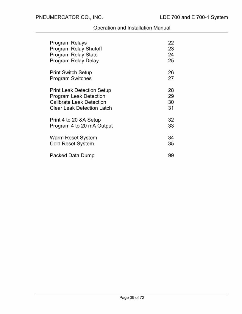
Program Relays 22 Program Relay Shutoff 23 Program Relay State 24 Program Relay Delay 25 Print Switch Setup 26 Program Switches 27 Print Leak Detection Setup 28 Program Leak Detection 29 Calibrate Leak Detection 30 Clear Leak Detection Latch 31 Print 4 to 20 &A Setup 32 Program 4 to 20 mA Output 33 Warm Reset System 34 Cold Reset System 35 Packed Data Dump 99
PNEUMERCATOR CO., INC. LDE 700 and E 700-1 System
Operation and Installation Manual
Page 40 of 72
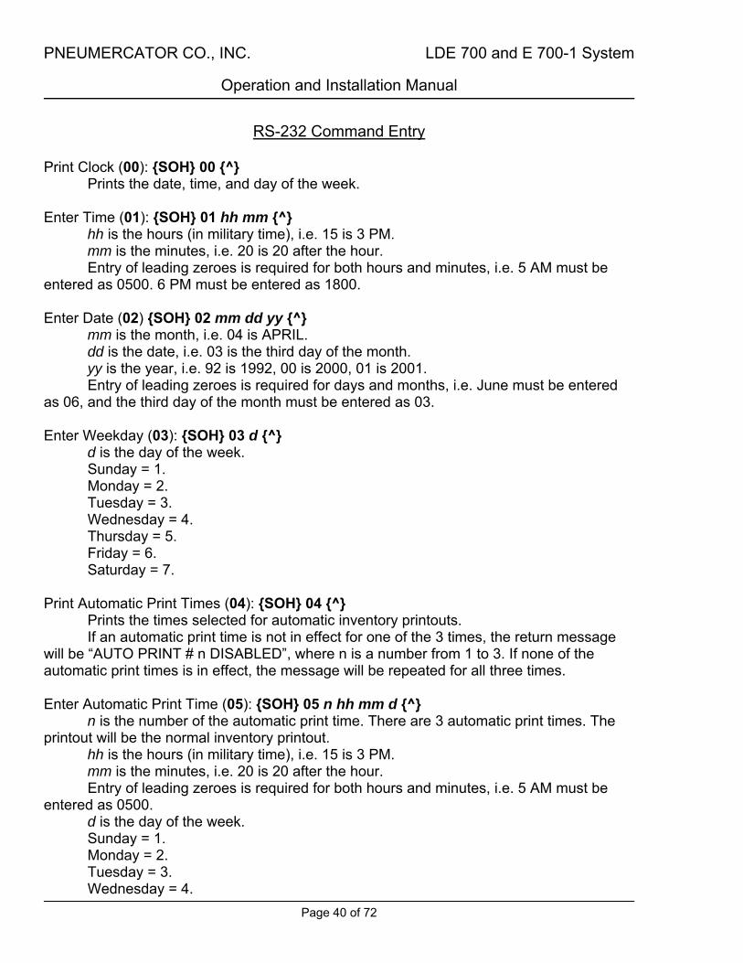
RS-232 Command Entry Print Clock (00): {SOH} 00 {^}
Prints the date, time, and day of the week. Enter Time (01): {SOH} 01 hh mm {^}
hh is the hours (in military time), i.e. 15 is 3 PM. mm is the minutes, i.e. 20 is 20 after the hour. Entry of leading zeroes is required for both hours and minutes, i.e. 5 AM must be
entered as 0500. 6 PM must be entered as 1800. Enter Date (02) {SOH} 02 mm dd yy {^}
mm is the month, i.e. 04 is APRIL. dd is the date, i.e. 03 is the third day of the month. yy is the year, i.e. 92 is 1992, 00 is 2000, 01 is 2001. Entry of leading zeroes is required for days and months, i.e. June must be entered
as 06, and the third day of the month must be entered as 03. Enter Weekday (03): {SOH} 03 d {^}
d is the day of the week. Sunday = 1. Monday = 2. Tuesday = 3. Wednesday = 4. Thursday = 5. Friday = 6. Saturday = 7.
Print Automatic Print Times (04): {SOH} 04 {^}
Prints the times selected for automatic inventory printouts. If an automatic print time is not in effect for one of the 3 times, the return message
will be “AUTO PRINT # n DISABLED”, where n is a number from 1 to 3. If none of the automatic print times is in effect, the message will be repeated for all three times. Enter Automatic Print Time (05): {SOH} 05 n hh mm d {^}
n is the number of the automatic print time. There are 3 automatic print times. The printout will be the normal inventory printout.
hh is the hours (in military time), i.e. 15 is 3 PM. mm is the minutes, i.e. 20 is 20 after the hour. Entry of leading zeroes is required for both hours and minutes, i.e. 5 AM must be
entered as 0500. d is the day of the week. Sunday = 1. Monday = 2. Tuesday = 3. Wednesday = 4.

PNEUMERCATOR CO., INC. LDE 700 and E 700-1 System
Operation and Installation Manual
Page 41 of 72
Thursday = 5. Friday = 6. Saturday = 7. If 0 is entered as the day of the week, all days are selected. If the command is entered in the form: {SOH} 05 n {^}, that automatic print time will
be disabled. Print High Alarm Setting (06): {SOH} 06 {^}
Prints the set point for the overfill alarm. Enter High Alarm Setting (07): {SOH} 07 nnnnn {^}
nnnnn is the level to set the alarm to in gallons, five (5) digits are required. Leading zeroes are required, i.e. 6000 gallons must be entered as 06000.
Print Low Alarm Setting (08): {SOH} 08 {^}
Prints the set point for the low level alarm. Enter Low Alarm Setting (09): {SOH} 09 nnnnn {^}
nnnnn is the level to set the alarm to in gallons, five (5) digits are required. Leading zeroes are required, i.e. 60 gallons must be entered as 00060.
Print Alarm Status (10): {SOH} 10 {^}
Prints all current alarms that are now ON in the system. High level, Low level, Switch 1, Switch 2, Loss alarms are profiled. The LDE 700 also prints the status of the Leak detection (or Switch(es) if so programmed) channels. Print Tank Parameters (11): {SOH} 11 {^}
Prints the setup parameters for the tank. The parameters printed are: tank product code and name; high level and low level alarm settings; tank capacity; tank diameter; and installation offset. Print offset Adjustment (12): {SOH} 12 {^}
Prints the setting of the offset adjustment. Enter Offset Adjustment (13): {SOH} 13 nnn {^}
nnn is the level to set the offset to (this level is entered in hundredths of an inch, i.e. 2 inches is entered as 200. The offset for a tank may range from -9.99 inches to +9.99 inches.
Leading zeroes are required, i.e. 0.50 inches of positive offset must be entered as 050.
If a negative offset is desired, it is preceded by a minus sign. No sign is required or allowed for a positive offset.
The offset for the tank is derived as follows: 1.First remove any pressurized or vapor recovery tubes from the dipstick
measurement opening. These tubes can cause a reading to vary by as much as 3 inches depending upon the pressure in the tank.

PNEUMERCATOR CO., INC. LDE 700 and E 700-1 System
Operation and Installation Manual
Page 42 of 72
2.Take a very careful dipstick reading with an accurate dipstick. Write down the reading.
3.Write down the fuel height in inches shown by the Gauge. 4.Subtract the Gauge reading from the dipstick reading
(Dipstick - Gauge = Difference) to get the Installation Offset and record it for reference. Print Product Name (14): {SOH} 14 {^}
Prints the name assigned to the tank contents. Enter Product Code (15): {SOH} 15 nn {^}
nn is the 2-digit number which represents the name of the product in the tank (see APPENDIX B). Print Inventory Report (16): {SOH} 16 {^}
Prints the current status of the tank for level in inches, and volume in gallons. Also prints the assigned tank name and a time and date stamp. Print System Setup (17): {SOH} 17 {^}
Prints system setup parameters. These parameters are: Serial number of system, automatic inventory printout times, clock data (time, date, day of week), the system software version, relay programming, horn programming, switch input programming, leak channel programming (LDE 700), RS-232 port programming, and 4 to 20 mA output programming. Print Horn Setup (18): {SOH} 18 {^}
Prints the setup conditions for the horn. Program Horn (19): {SOH} 19 c {^}
c is the condition that will actuate the horn. More than one condition may be set to actuate the horn. If more than one condition is set for the horn, the programming must be repeated for each condition.
0 = horn disabled. 1 = horn activated by High Level Alarm. 2 = horn activated by Low Level Alarm. 3 = horn activated by Switch 1 Alarm. 4 = horn activated by Switch 2 Alarm. 5 = horn activated by LDE 1 oil Alarm (LDE 700). 6 = horn activated by LDE 2 oil Alarm (LDE 700). 7 = horn activated by LDE 1 water Alarm (LDE 700). 8 = horn activated by LDE 2 water Alarm (LDE 700). 9 = horn activated by Loss Alarm.
*Conditions 5,6,7,8 not available with E 700-1. Minus sign (-) before condition number disables that condition.

PNEUMERCATOR CO., INC. LDE 700 and E 700-1 System
Operation and Installation Manual
Page 43 of 72
Program Horn Shutoff (20): {SOH} 20 t {^} t is the time for automatic horn shutoff after alarm actuation. There is a 10-minute
delay built-in between horn actuations for the same condition. 0 = manual horn shutoff (must be silenced with RESET pushbutton on enclosure
cover. 1 to 7 = will automatically silence after programmed number of minutes. May be
manually silenced with RESET pushbutton on enclosure cover. Print Relay Setup (21): {SOH} 21 {^}
Prints the setup conditions for all 4 relays. Program Relays (22): {SOH} 22 n c {^}
n is the number of the relay that is being setup. This is relay 1 to relay 4.
c is the condition that will actuate that relay. More than one condition may be set to actuate the relay being programmed. If more than one condition is set for that relay, the programming must be repeated for each condition.
1 = relay activated by High Level Alarm. 2 = relay activated by Low Level Alarm. 3 = relay activated by Switch 1 Alarm. 4 = relay activated by Switch 2 Alarm. 5 = relay activated by LDE 1 oil Alarm (LDE 700). 6 = relay activated by LDE 2 oil Alarm (LDE 700). 7 = relay activated by LDE 1 water Alarm (LDE 700). 8 = relay activated by LDE 2 water Alarm (LDE 700). 9 = relay activated by Loss Alarm.
*Conditions 5,6,7,8 not available with E 700-1. Minus sign (-) before condition number disables that condition. Program Relay Shutoff (23): {SOH} 23 n tt {^}
n is the number of the relay that is being setup. tt is the time for automatic relay shutoff after alarm actuation. 00 = no automatic shutoff (relay remains actuated as long as alarm condition exists.) 01 to 15 = will automatically toggle relay state after programmed number of minutes.
Program Relay State (24): {SOH} 24 n s {^}
n is the number of the relay that is being setup. s is the state for an inactive relay output. 0 = normally deenergized (relay energized after alarm). 1 = normally energized (relay deenergizes after alarm). This condition can also be
used to detect a power failure on a relay not in alarm condition.

PNEUMERCATOR CO., INC. LDE 700 and E 700-1 System
Operation and Installation Manual
Page 44 of 72
Program Relay Delay (25): {SOH} 25 n c {^} n is the number of the relay that is being setup. c is the time for relay actuation after alarm condition. 0 = no delay after alarm before relay actuates. 1 = 5 minute delay after alarm before relay actuates.
Print Switch Setup (26): {SOH} 26 {^}
Prints the setup conditions for both switches. Program Switches (27): {SOH} 27 n s {^}
n is the number of the switch that is being setup. s is the state of the switch. This programs the state of the switch input in a non-alarm condition. 0 = programmed as normally open switch input. 1 = programmed as normally closed switch Input.
Print Leak Detection (LDE) Setup (28): {SOH} 28 {^}
Prints the setup conditions for both leak channels. *Not available with E 700-1. Program Leak Detection (LDE) (29): {SOH} 29 n s {^}
n is the number of the leak channel that is being setup. This is LDE 1 or LDE 2.
s is the state of the leak channel. 0 = programmed as leak channel. 1 = programmed as normally open switch input. (Wired to R & W) 2 = programmed as normally closed switch input. (Wired to R & W)
*Not available with E 700-1. Calibrate Leak Detection (LDE) (30): {SOH} 30 {^}
Calibrates the leak detection sensors. The sensors must be clean and dry and in air. If the sensors are in oil or water, clean and dry them off before calibrating. *Not available with E 700-1. Clear Leak Detection (LDE) Latch (31): {SOH} 31 {^}
Clears the alarm memory latch for both leak detector channels. *Not available with E 700-1. Print 4 to 20 mA Setup (32): {SOH} 32 {^}
Prints the setup condition for the optional 4 to 20 mA output. Program 4 to 20 mA Output (33): {SOH} 33 s {^}
Programs the optional 4 to 20 mA output. 4 mA output is an empty tank (0 gallons or inches). 20 mA output is a full tank (100% of tank volume or height).
0 = programmed for percent volume. 1 = programmed for percent height.
PNEUMERCATOR CO., INC. LDE 700 and E 700-1 System
Operation and Installation Manual
Page 45 of 72
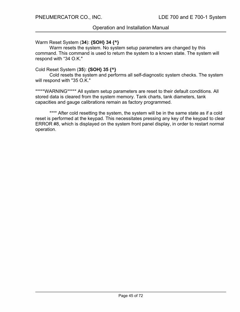
Warm Reset System (34): {SOH} 34 {^} Warm resets the system. No system setup parameters are changed by this
command. This command is used to return the system to a known state. The system will respond with “34 O.K." Cold Reset System (35): {SOH} 35 {^}
Cold resets the system and performs all self-diagnostic system checks. The system will respond with "35 O.K."
*****WARNING***** All system setup parameters are reset to their default conditions. All stored data is cleared from the system memory. Tank charts, tank diameters, tank capacities and gauge calibrations remain as factory programmed.
**** After cold resetting the system, the system will be in the same state as if a cold
reset is performed at the keypad. This necessitates pressing any key of the keypad to clear ERROR #8, which is displayed on the system front panel display, in order to restart normal operation.

PNEUMERCATOR CO., INC. LDE 700 and E 700-1 System
Operation and Installation Manual
Page 46 of 72
LDE 700, E 700-1 Packed (computer) Data Format Packed data is requested from the system by sending the ASCII sequence: SOH, 9,
9, CTRL (in hex: 01H, 39H, 39H,...) via the RS-232 port. CTRL may be any control character, such as CR (0DH) or LF (0AH).
The data transmitted is sent in ASCII-coded format with the information in the following
order: header; clock info; alarm, horn, switch, leak, & relay statuses; volume measurement; product height; checksum; footer.
HEADER (3 BYTES):
3 bytes ASCII consisting of 01H(SOH), 0DH and 0AH (newline). The header is not Included in the checksum.
CLOCK INFO (13 BYTES): Month (2 bytes) - 1 to 12, coded as 30H, 31H to 31H, 32H Day (2 bytes) - 1 to 31, coded as 30H, 31H to 33H, 31H Year (2 bytes) 00 to 99, coded as 30H, 30H to 39H, 39H Hours (2 bytes) - 00 to 23, coded as 30H, 30H to 32H, 33H Minutes (2 bytes) - 00 to 59, coded as 30H, 30H to 35H, 39H Seconds (2 bytes) - 00 to 59, coded as 30H, 30H to 35H, 39H Weekday (1 byte) - 1 to 7, coded as 31H to 37H
(Sunday = 1) ALARM, HORN, SWITCH, LEAK, and RELAY STATUSES (16 BYTES):
Each byte is a 0, coded as 30H for OFF or 1, coded as 31H for ON. The bytes are in the following order:
1. High (overfill) alarm 2. Low alarm 3. Horn status 4. Relay 1 5. Relay 2 6. Relay 3 7. Switch 1 8. Switch 2 9. Relay 4 10. Leak channel 1 air LED 11. Leak channel 1 oil LED 12. Leak channel 1 water LED 13. Leak channel 2 air LED 14. Leak channel 2 oil LED 15. Leak channel 2 water LED 16. Theft (loss) alarm * NOTE - WITH E 700-1 THE LEAK INFORMATION IS ALL SET TO 0 (30H)

PNEUMERCATOR CO., INC. LDE 700 and E 700-1 System
Operation and Installation Manual
Page 47 of 72
MEASUREMENTS FOR THE TANK (8 BYTES): Volume (4 bytes) - volume is stored in gallons as a hex number 0000H to 0FFFFH
(ranging from 0 to 65535 gallons) that is converted into 4 nibbles that are sent as ASCII (9H is sent as 39H).
Inches (4 bytes) - level is stored as inches times 100 (ranging from 0.00 inches to 655.35 inches). Data is sent the same way as with volume.
CHECKSUM (4 BYTES):
4 bytes ASCII. Each ASCII byte transmitted is added to a 16-bit accumulator with no overflow or carry or wraparound. The final sum is converted into 4 hex nibbles which are converted into ASCII. The header (01H, 0DH, 0AH) and the footer (0DH, 0AH, 03H) are not included in the checksum.
FOOTER (3 BYTES):
3 bytes ASCII consisting of 0DH, 0AH, (newline) and 03H. The footer is not included in the checksum.
PNEUMERCATOR CO., INC. LDE 700 and E 700-1 System
Operation and Installation Manual
Page 48 of 72
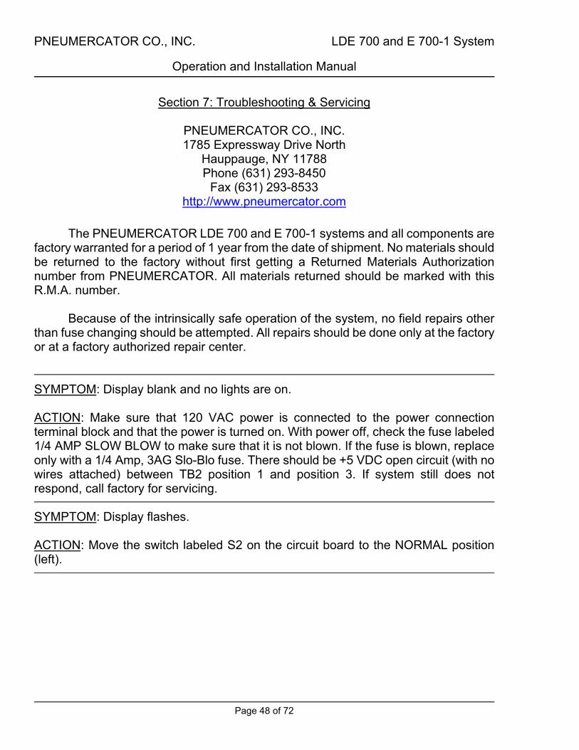
Section 7: Troubleshooting & Servicing
PNEUMERCATOR CO., INC. 1785 Expressway Drive North
Hauppauge, NY 11788 Phone (631) 293-8450
Fax (631) 293-8533 http://www.pneumercator.com
The PNEUMERCATOR LDE 700 and E 700-1 systems and all components are
factory warranted for a period of 1 year from the date of shipment. No materials should be returned to the factory without first getting a Returned Materials Authorization number from PNEUMERCATOR. All materials returned should be marked with this R.M.A. number.
Because of the intrinsically safe operation of the system, no field repairs other
than fuse changing should be attempted. All repairs should be done only at the factory or at a factory authorized repair center.
SYMPTOM: Display blank and no lights are on. ACTION: Make sure that 120 VAC power is connected to the power connection terminal block and that the power is turned on. With power off, check the fuse labeled 1/4 AMP SLOW BLOW to make sure that it is not blown. If the fuse is blown, replace only with a 1/4 Amp, 3AG Slo-Blo fuse. There should be +5 VDC open circuit (with no wires attached) between TB2 position 1 and position 3. If system still does not respond, call factory for servicing. SYMPTOM: Display flashes. ACTION: Move the switch labeled S2 on the circuit board to the NORMAL position (left).

PNEUMERCATOR CO., INC. LDE 700 and E 700-1 System
Operation and Installation Manual
Page 49 of 72
SYMPTOM: System always displays the minimum or maximum gaugeable setting no matter how much product is in the tank. SYMPTOM: System displays a negative reading or Error Code 9 (volume measurement underrange). SYMPTOM: System displays a reading greater than full capacity or Error Code 7 (volume measurement overrange). ACTION: Make sure that all wires are connected properly from the tank level transmitter to the tank input (TB2). Make sure that there are no shorted or open wires. Make sure that there is no water in a wire splice or in transmitter housing. See Testing the Tank Level Transmitter section on the next page. Make sure that the gauge calibrations are set properly (see keypad commands numbers 49 and 50). If system still does not respond call factory for servicing. SYMPTOM: Switch light is always on, or goes on when it shouldn't. ACTION: Make sure that Switch is working properly and that the switch input is programmed for the proper state. Make sure that the switch has no current leakage in an open state. If system still does not respond call factory for servicing. SYMPTOM: Leak detection channel gives false water alarm.
LIGHT INDICATIONS
Dry Water Hydrocarbon Meaning off on off water alarm ACTION: Check to make sure that the sensor is in contact only with air. Make sure that the ground wire (marked B) and the sensor input wire (marked W) have continuity from the sensor to the alarm console. Make sure that the sensor input wire (marked W) is not shorted to power. Place system in Calibrate mode with the sensor in air. If sensor still does not work properly, call factory for servicing.

PNEUMERCATOR CO., INC. LDE 700 and E 700-1 System
Operation and Installation Manual
Page 50 of 72
SYMPTOM: Leak detection channel gives false alarms. ACTION: Check to make sure that the sensor is in contact only with air. Pull sensor from installation and make sure that it is not fouled or clogged. If sensor is fouled or clogged, clean with soap and water solution or a mild solvent and dry and unclog with compressed air. Place system in Calibrate mode with the sensor in air. Check all wiring for continuity, proper connections and make sure that there are no shorts. If sensor still does not work properly, call factory for servicing.
When the sensor has been immersed in water, it takes a period of time for the
sensor to drain completely and dry. During this time the sensor will oscillate between water/hydrocarbon and hydrocarbon/air readings. This may cause the hydrocarbon or water alarm to latch into the system memory. This may be cleared when the sensor is dry and in air by calibrating the leak detection sensor.
Testing the Gauge
In order to verify that the gauge is properly reading the tank unit, first shut off
power to the gauge. Then disconnect the tank unit from the barrier block. A potentiometer (variable resistor or “pot”) of a value of about one thousand to ten thousand ohms (the exact value is not critical) should be connected to the barrier block. One end terminal of the pot is connected to terminal 1 (Red), the other end terminal is connected to terminal 3 (Black), and the middle terminal of the pot (the wiper) is connected to terminal 2 (White). The gauge should then be powered up again. The gauge readings will vary as the position of the pot wiper is changed. At the extreme ends of the pot's rotational angle, the gauge readings may show a negative reading or a reading greater than the tank's capacity, but the pot can be used to move the gauge readings over the full span of possible volumes.
*** The readings from the potentiometer should not be used to calibrate the gauge, or to judge the accuracy of the gauge, as the potentiometer is only an approximation of the tank unit, which is custom made and calibrated for the particular tank.
Testing the Tank Level Transmitter In order to test the tank level transmitter unit, it must be disconnected from the
gauge unit. Always shut off power to the gauge when connecting or disconnecting the tank units, the power cable, and any wires to the optional switches. With the tank unit disconnected from the gauge, use an ohmmeter to measure the resistance between the Red and the Black wires of the tank unit. The measurement should be 2000 on the 2-501 tank transmitter. The resistance of the 2-412 is 72.5 per inch of sensing length. If the readings are incorrect, they should be repeated where the tank unit is

PNEUMERCATOR CO., INC. LDE 700 and E 700-1 System
Operation and Installation Manual
Page 51 of 72
joined to the conduit wires. These readings should be made with the conduit wires disconnected from the tank unit. If the readings are now correct, then there is a problem with the conduit wires. Always make sure that the wires running through the conduit follow the proper color-coding. Incorrect readings will result if the color-coding is not followed.
2-412: With the float at the bottom and the top of travel, the reading between White to Black and White to Red respectively is 0. The reading between the Black and White wires will increase as the float moves up, and will be a ratio of the percentage of float travel to overall sensing length. Example: Sensing length = 80 inches.
Float travel = 20 inches. Overall resistance = 5800 (Red to Black).
Answer: Black to White resistance = 1450. Red to White resistance = 4350.
If the float has been removed from the tube of the 2-412, make sure that it is replaced facing in the same orientation. The magnet in the float will only work if it is facing in the correct orientation.
The interior of the 2-412 is hermetically sealed and no field repairs can be made on it. The 2-501 contains no parts that can be field repaired.
2-501: With the float arm at bottom of travel, Black to White is 0. Black to Red is always 2000. The Black to White reading will increase as the float moves up, and will be a ratio of the percentage of float arm travel to overall float arm travel. The Red to White resistance will vary from unit to unit, and should be measured with the float arm at the top of travel. Example: Overall float arm travel = 80 inches.
Example float arm travel = 20 inches. Overall resistance = 2000. Red to White (at top of travel) = 280 (measured). Black to White span = 1720 (calculated).
Answer: Black to White resistance = 430. Red to White resistance = 1290.
*** Make sure that all splices are contained in waterproof junction boxes or are potted or sealed to be waterproof. Part number 10585-3 is an available wiring waterproofing kit. Make sure that no water can enter the housing of the 2-412 tank unit.

PNEUMERCATOR CO., INC. LDE 700 and E 700-1 System
Operation and Installation Manual
Page 52 of 72
Figure 1 - 2-412 Installation
STEPS FOR A TROUBLE FREE INSTALLATION
STEP 1 - EXAMINE THE SHIPMENT
1.1 Each system consists of two main components, which are packed separately, the transmitter float assembly and the indicator unit. Make sure you have both parts. If cartons are missing or damaged, have the fact noted on the delivery receipts to permit a claim to be filed against the transportation company.
1.2 Match the transmitter float assembly Serial No. with the Serial No. on indicating unit to insure compatibility.
1.3 The transmitter float assembly should be checked for damage, which may have occurred during shipping. The float switch should move freely from the bottom stop to the top stop on the rod. If the float can be rotated on the rod, then the float guides have been damaged. If any problems arise, contact the factory.
DO NOT ATTEMPT TO INSTALL DAMAGED UNITS.
STEP 2 - MAKE SURE THE SYSTEM MATCHES YOUR JOB
2.1 Compare the actual tank dimensions and capacity with the tank dimensions and capacity on the packing slip and the transmitter mounting tag to insure compatibility.
2.2 Standard construction is suitable for most petroleum products.
2.3 For potentially corrosive liquids, verify the liquid's compatibility with stainless steel and Teflon. When the unit is supplied with a water switch, verify the compatibility of the liquid with nitrophyl.
2.4 Verify that the tank is set level. To obtain accurate readings from a tilted tank, the indicator must be ordered with a special calibration.
BULLETIN 104-700 Series

PNEUMERCATOR CO., INC. LDE 700 and E 700-1 System
Operation and Installation Manual
Page 53 of 72
Figure 1 - 2-412 Installation (Continued)
STEP 3 - SELECT THE CORRECT LOCATION FOR THE INSTALLATION OF THE TRANSMITTER FLOAT ASSEMBLY
3.1 The transmitter float assembly should be installed through a 4” NPT half coupling in the top of the tank as shown in figure 1-1. It is recommended that a strike plate be situated directly below the coupling. If the unit is to be standpipe mounted, it should have been ordered for the special mounting height (*) and installed as shown in figure 1-2.
3.2 When the tank is indoors, sufficient clearance must be provided between tank and ceiling to permit installation and removal of the transmitter float assembly.
3.3 When the tank is underground, a suitable chamber and cover should be provided to permit installation and removal of the transmitter float assembly should it ever be required. This is especially important when the tank is to be covered with pavement or concrete. Do not bury tank unit.
STEP 4 - INSTALL WITH CARE
4.1 Screw the mounting bushing 1-1/16” into the proper opening in the top of the tank (see figure 1-1). There should be a clearance of at least 2.0" between the bottom of the probe and the bottom of the tank (see figure 1-3).
4.2 When using a standpipe, screw the mounting bushing 1-1/16” into the 4” NPT coupling on top of the standpipe (see figure 1-2). There should be a clearance of at least 2.0” between the bottom of the probe and the bottom of the tank (see figure 1-3).
FIG. 1-1STANDARD TANK MOUNT
(BUSHING)
TANKO.D.
4” NPT OPENING
4” X 1” BUSHING(BY P.C.O.)
1-1/16 TYP.
MTG.HT.
4" NPTOPENING
TANKO.D.
* MTG.HT.
FIG. 1-2STANDPIPE MOUNT
(BUSHING)
1-1/16 TYP.
4" X 1" BUSHING(BY P.C.O.)
4" NPT COUPLING(BY CUSTOMER)
4" NPT SCHEDULE40 PIPE (BY CUST.)
BULLETIN 104-700 Series
FIG. 1-3
3" NOM. (2" MIN.)

PNEUMERCATOR CO., INC. LDE 700 and E 700-1 System
Operation and Installation Manual
Page 54 of 72
Figure 2 - 2-501 Installation
STEPS FOR A TROUBLE FREE INSTALLATION 1. Examine the shipment 2. Make sure the system matches your job 3. Select the correct location for the transmitter 4. Install the transmitter float assembly with care
STEP 1 - EXAMINE THE SHIPMENT
1.1 The system consists of two components, which are packed separately, the transmitter and the indicator. Make sure you have both parts. If cartons are missing or damaged note the delivery receipts to permit a claim to be filed against the transportation company.
DO NOT ATTEMPT TO INSTALL DAMAGED UNITS. 1.2 Match the serial no.'s on the transmitter and indicator to insure compatibility.
STEP 2 - MAKE SURE THE SYSTEM MATCHES YOUR JOB
2.1 Compare the dimensions and capacity on the packing slip with the tank drawing to insure compatibility. 2.2 Check that the tank is vented to atmosphere unless the order shows the system was designed for a pressurized tank. 2.3 Verify that the tank contents will not corrode the unit's wetted parts (Alum., Brass, Buna-N, nylon, 303 Stainless). Standard construction is suitable for most petroleum products. 2.4 Verify that the tank is set level. (Tilted tanks require special calibration.)
TRANSMITTER
FLOAT
SEE DWG.
SUPPLIED
FOR PROPER
DIMENSION
CENTERLINEOF
TANK
FIG 2-1
SPLICEKIT
10-32 MTG.SCREWS
NOTE: THE FLOAT ARM SHOULD SWING UPWARDS
FLANGENIPPLEASSY.
FIG 2-1A
TOWARDS THE CONNECTOR ON THE HOUSING.
BULLETIN 105--700 Series

PNEUMERCATOR CO., INC. LDE 700 and E 700-1 System
Operation and Installation Manual
Page 55 of 72
Figure 2 - 2-501 Installation (Continued)
STEP 3 - SELECT THE CORRECT LOCATION FOR THE TRANSMITTER 3.1 Standard installation requires a 2” half coupling in the top of the tank. The fulcrum pipe will then reach the mid-point of tank as required for accurate measurement If the transmitter is to be installed through a manway or a riser, it must be ordered with an extra long fulcrum pipe. THERE IS NO WAY TO ADJUST THE SYSTEM FOR ACCURATE GAUGING IF THE PIVOT LEVER IS NOT CORRECTLY POSITIONED. (See Figure 2-1 & 2-2) 3.2 The float arm must swing in an arc along the axis of the tank without hitting the end of the tank or other obstructions and not extend under manways or fill lines. 3.3 When tank is indoors, sufficient clearance must be provided to permit installation of the fulcrum pipe, which is approximately one-half the tank diameter plus 11 inches. 3.4 When the tank is underground or covered by pavement, a chamber should be provided to permit access to the transmitter. Covers to access chambers should provide clearance for installation and removal of the fulcrum pipe. (See 3.3 above).
STEP 4 - INSTALL THE TRANSMITTER WITH CARE 4.1 The transmitter should be installed when the tank is empty. Although it is possible to install when the liquid is below the tank midpoint, there is no way to verify factory settings and adjustments. 4.2 The flange / nipple has been preremoved to protect the float arm assembly during installation. DO NOT reattach until after the float arm assembly is in the tank. 4.3 Screw the flange / nipple into the proper tank opening. Align flange so float will rise and fall along the centerline of tank when transmitter assembly is installed. (Flange must be level). *Position gasket on flange using a suitable sealing compound on both sides.
NOTE: THE DIMENSION BETWEEN THE TANK TOP AND TOP OF THE FLANGE (SEE ATTACHED TAG) MUST BE EXACT FOR THE PIVOT TO REACH THE MIDPOINT OF THE TANK AS REQUIRED FOR ACCURATE GAUGING.
4.4 Attach the float am to the pivot lever using the two bolts furnished. Insert the stroke setting cord through hole in float arm, then through hole in the nipple and knot ends together. (NOTE: MUST BE RE-INSTALLED UPON COMPLETION OF INSTALLATION.) (See Figures. 2-2 & 2-2A) 4.5 Insert the transmitter float assembly through the flange / nipple. (See Figure 2-3.) Note: the direction of float travel is toward the cable in the transmitter housing. DO NOT LET FLOAT ARM SWING BACKWARDS DURING INSTALLATION! 4.6 Attach the transmitter float assembly to the flange / nipple using the screws from 4.2. Tighten all five screws evenly to assure a tight seal. (See Fig. 2-1A). 4.7 Raise and lower the float arm with the stroke setting cord. Make certain that the float and arm move freely (DO NOT FORCE) from bottom to top of the tank unobstructed.
FULCRUM PIPE
FLOATARM
STROKE SETTINGCORD
KNOTPIVOT LEVER
HOLE IN FLOATARMFig. 2-2
Fig. 2-2 ASEALING PLUG
KNOTTED ENDS OFLOOPED CORD
FLANGE / NIPPLE
TANKBOTTOM
PULL FLOAT UP WITH CORD TOPREVENT JAMMING ONTANKBOTTOM
ATTACHTANK ENDHOUSING TO NIPPLEDFLANGE WITH FIVESCREWS
A B C
Fig. 2-3
BULLETIN 105--700 Series

PN
EU
ME
RC
AT
OR
CO
., INC
. LD
E 700 and E
700-1 System
Operation and Installation M
anual
Page 56 of 72
Fig
ure 3 - 9-901 In
stallation
BOTTOM
ELECTRONICSENSOR
18/3 CABLE
MOUNTINGBUSHING(BY CUST.)
MARK ON CABLE
CORD CONNECTOR(SUPPLIED)
CABLEMEASUREMENT
OPENING2" MIN.
CONDUIT(BY CUST.)
25 FT. CABLE(SUPPLIED)
MOUNTINGBUSHING
(BY CUST.)
MANHOLE (BY CUST.)
1/2" NPT LIQUID-TITECORD CONNECTORS(SUPPLIED)
JUNCTION BOX-NEMA 4 ORBETTER (BY CUSTOMER)
NOTES:1. MANHOLE: 1.1) SUPPLIED BY CUSTOMER.2. JUNCTION BOX: 2.1) SUPPLIED BY CUSTOMER. TO BE NEMA 4 OR BETTER. 2.2) OPTIONAL SPLICE KIT IS AVAILABLE (P/N 10585-3).3. SENSOR: 3.1) SENSOR IS SUPPLIED AS AN ASSEMBLY WITH 25 FT. OF CABLE ATTACHED. 3.2) MOUNTING REQUIRES A 2" MINIMUM OPENING. TWO 1/2" NPT LIQUID-TITE CORD CONNECTORS ARE SUPPLIED. 3.3) CABLE IS 18/3.
INSTALLATION INSTRUCTIONS (REFER TO FIGURE 1)
1. IF YOUR TANK MANUFACTURER/BRAND IS NOT LISTED IN THE TABLE ABOVE, CALCULATE YOUR CABLE MEASUREMENT BY USING D ÷ 2 (CIRCUMFERENCE DIVIDE BY TWO). 'D' IS THE DIAMETER OF THE TANK.2. UNROLL THE SENSOR / CABLE ASSEMBLY. MEASURE FROM THE SENSOR'S BOTTOM UP THE CABLE UNTIL YOU REACH YOUR CABLE MEASUREMENT (FROM INSTRUCTION 2) AND MARK THE CABLE AT THAT POINT.3. FEED THE CABLE THROUGH THE BOTTOM OF THE MOUNTING BUSHING AND CORD CONNECTOR UNTIL YOU SEE THE MARK ON THE CABLE. INSERT THE SENSOR AND CABLE THROUGH THE TANK OPENING.4. SCREW IN THE MOUNTING BUSHING AND CONNECTOR.5. TIGHTEN THE CONNECTOR WITH THE CABLE MARK IN THE CORRECT POSITION.6. USING THE PROPER CONSOLE WIRING DRAWING, WIRE TO THE JUNCTION BOX OR SPLICE KIT AND THEN TO THE CONSOLE. FOLLOW LOCAL WIRING CODES AND EXPLOSION-HAZARD ELECTRICAL PRACTICES IF REQUIRED.
FIGURE 1
MODEL 9-901ANNULAR SPACE INSTALLATION
ELECTRONICSENSOR
ANNULARSPACE
CABLE MEASUREMENTTANKSIZE
MANUFACTURER/BRAND
MARKCABLE AT
4 FT.4 FT.
OWENS CORNING DWTXERXES DWT
81"
OWENS CORNING DWTXERXES DWT6 FT.
6 FT.118"
OWENS CORNING DWTXERXES DWT8 FT.
8 FT.149.5"
OWENS CORNING DWTXERXES DWT
10 FT.193.5"
OWENS CORNING DWTXERXES DWT
222"
10 FT.12 FT.12 FT.
MODEL 9-901 SENSOR
N/A
N/A
N/A
R. KHARE 03/23/93
B 47876 10468 B
INSTALLATION DRAWING
NONE 1 OF 1
B SEE REVISION SHEET FOR THIS AND OTHER REVISIONHISTORY 04/16/13 CHR
DATEAPPROVALS
DO NOT SCALE DRAWING
CAGE CODE
ANGLES± 0°30'
FRACTIONS
MATERIAL:
FINISH:
PART NUMBER:
UNLESS OTHERWISE SPECIFIEDDIMENSIONS ARE IN INCHES
DECIMALS.XX ±.01.XXX ±.005
± 1/64
DRAWN BY
CHECKED BY
SCALE
DESCRIPTION
SIZE
SHEET
DRAWING NO. REV.
REV APP.BYDATEDESCRIPTION
REVISIONSUSED ONNEXT ASSY
APPLICATION
Liquid Level Control SystemsPNEUMERCATOR

PN
EU
ME
RC
AT
OR
CO
., INC
. LD
E 700 and E
700-1 System
Operation and Installation M
anual
Page 57 of 72
Fig
ure 4 - 9-902 In
stallation
INSTALLATION INSTRUCTIONS(REFER TO FIGURE 1)
1. MEASURE YOUR MOUNTING HEIGHT. (THE DISTANCE FROM THE TOP OF THE OPENING TO THE BOTTOM OF THE MONITORING PIPE OR CONTAINMENT SUMP.2. YOUR MOUNTING HEIGHT + "A" - .50 IS YOUR CABLE MEASUREMENT.3. UNROLL THE SENSOR / CABLE ASSEMBLY. MEASURE FROM THE SENSOR'S BOTTOM UP THE CABLE UNTIL YOU REACH YOUR CABLE MEASUREMENT (FROM INSTRUCTION 2) AND MARK THE CABLE AT THAT POINT.4. FEED THE CABLE THROUGH THE BOTTOM OF THE MOUNTING BUSHING AND CORD CONNECTOR UNTIL YOU SEE THE MARK ON THE CABLE. INSERTTHE SENSOR AND CABLE THROUGH THE TANK OPENING.5. SCREW IN THE MOUNTING BUSHING AND CONNECTOR.6. TIGHTEN THE CONNECTOR WITH THE CABLE MARK IN THE CORRECT POSITION.7. USING THE PROPER CONSOLE WIRING DRAWING, WIRE TO THE JUNCTION BOX OR SPLICE KIT AND THEN TO THE CONSOLE. FOLLOW LOCAL WIRING CODES AND EXPLOSION-HAZARD ELECTRICAL PRACTICES IF REQUIRED.
ELECTRONICSENSOR
MANHOLE (BY CUST.)
MODEL 9-902MONITORING PIPE INSTALLATION
MODEL 9-902SUMP INSTALLATION
1/2" NPT LIQUID-TITECORD CONNECTOR(SUPPLIED)
JUNCTION BOX-NEMA 4 ORBETTER (BY CUSTOMER)
25 FT. CABLE(SUPPLIED)
ELECTRONICSENSOR
MONITORINGPIPE
MOUNTINGBUSHING
(BY CUST.)
CONDUIT(BY CUST.)
INNERTANK
25 FT. CABLE(SUPPLIED)
ANNULARSPACE ELECTRONIC
SENSOR
CONTAINMENTSUMP
CONDUIT(BY CUST.)MANHOLE
(BY CUST.)MOUNTING
BUSHING(BY CUST.)
TANK
JUNCTION BOX-NEMA 4 ORBETTER (BY CUSTOMER)
1/2" NPT LIQUID-TITECORD CONNECTOR(SUPPLIED)
MODEL 9-902PIPING SUMP OR
MANHOLE INSTALLATION
.50
NOTES:1. MANHOLE: 1.1) SUPPLIED BY CUSTOMER.2. JUNCTION BOX: 2.1) SUPPLIED BY CUSTOMER. TO BE NEMA 4 OR BETTER. 2.2) OPTIONAL SPLICE KIT IS AVAILABLE (P/N 10585-3).3. SENSOR: 3.1) SENSOR IS SUPPLIED AS AN ASSEMBLY WITH 25 FT. OF CABLE ATTACHED. 3.2) MOUNTING REQUIRES A 2" MINIMUM OPENING. TWO 1/2" NPT LIQUID-TITE CORD CONNECTORS ARE SUPPLIED. 3.3) CABLE IS 18/3.
FIGURE 1
"A"
MTG.HT.
CABLEMEASUREMENT
CONDUIT(BY CUST.)
JUNCTION BOX-NEMA 4OR BETTER (BY CUST.)
DOUBLEWALLTANK
1/2" NPTLIQUID-TITECORD CON.(SUPPLIED)
25 FT. CABLE(SUPPLIED)
PIPING SUMP(BY CUST.)
MANWAY(BY CUST.)
CUSTOMERSEQUIPMENT
MARK ON CABLE
OPENING2" MIN.
ELECTRONICSENSOR
BOTTOM
18/3 CABLE
CORD CONNECTOR(SUPPLIED)
MOUNTINGBUSHING(BY CUST.)
CONCRETECONTAINMENT
LEAKSWITCH
MONITORINGPIPE
TANK
25 FT. CABLE(SUPPLIED)
MODEL 9-902ABOVE GROUND INSTALLATION
B SEE REVISION SHEET FOR THIS AND OTHER REVISIONHISTORY 04/16/13 CHR
N/A
N/A
N/A
R. KHARE 03/23/93
C 47876 10469 B
INSTALLATION DRAWING
NONE 1 OF 1
MODEL 9-902 SENSOR
DATEAPPROVALS
DO NOT SCALE DRAWING
CAGE CODE
ANGLES± 0°30'
FRACTIONS
MATERIAL:
FINISH:
PART NUMBER:
UNLESS OTHERWISE SPECIFIEDDIMENSIONS ARE IN INCHES
DECIMALS.XX ±.01.XXX ±.005
± 1/64
DRAWN BY
CHECKED BY
SCALE
DESCRIPTION
SIZE
SHEET
DRAWING NO. REV.
REV APP.BYDATEDESCRIPTION
REVISIONSUSED ONNEXT ASSY
APPLICATION
Liquid Level Control SystemsPNEUMERCATOR

PN
EU
ME
RC
AT
OR
CO
., INC
. LD
E 700 and E
700-1 System
Operation and Installation M
anual
Page 58 of 72
Fig
ure 5 - 9-903 In
stallation
BOTTOM
ELECTRONICSENSOR
18/3 CABLE
MARK ON CABLE
CORD CONNECTOR(SUPPLIED)
MTG.HT.
LEAK TUBECOVER
NOTES:1. MANHOLE: 1.1) SUPPLIED BY CUSTOMER.2. JUNCTION BOX: 2.1) SUPPLIED BY CUSTOMER. TO BE NEMA 4 OR BETTER. 2.2) OPTIONAL SPLICE KIT IS AVAILABLE (P/N 10585-3).3. SENSOR: 3.1) SENSOR IS SUPPLIED AS AN ASSEMBLY WITH 25 FT. OF CABLE ATTACHED. 3.2) MOUNTING REQUIRES A 2" MINIMUM OPENING. TWO 1/2" NPT L IQUID-TITE CORD CONNECTORS ARE SUPPLIED. 3.3) CABLE IS 18/3.
INSTALLATION INSTRUCTIONS(REFER TO FIGURE 1)
1. MEASUREYOUR MOUNTING HEIGHT. (THE DISTANCE FROM THE TOP TO THE BOTTOM OF THE LEAK DETECTION TUBE).2. ADD 1" TO YOUR MOUNTING HEIGHT TO FIND YOUR CABLE MEASUREMENT.3. UNROLL THE SENSOR / CABLE ASSEMBLY. MEASURE FROM THE SENSOR'S BOTTOM UP THE CABLE UNTIL YOU REACH YOUR CABLE MEASUREMENT (FROM INSTRUCTION 2) AND MARK THE CABLE AT THAT POINT.4. FEED THE CABLE THROUGH THE BOTTOM OF THE MOUNTING BUSHING AND CORD CONNECTOR UNTIL YOU SEE THE MARK ON THE CABLE. INSERTTHE SENSOR AND CABLE THROUGH THE TANK OPENING.5. SCREW IN THE MOUNTING BUSHING AND CONNECTOR.6. TIGHTEN THE CONNECTOR WITH THE CABLE MARK IN THE CORRECT POSITION.7. USING THE PROPER CONSOLE WIRING DRAWING, WIRE TO THE JUNCTION BOX OR SPLICE KIT AND THEN TO THE CONSOLE. FOLLOW LOCAL WIRING CODES AND EXPLOSION-HAZARD ELECTRICAL PRACTICES IF REQUIRED.
FIGURE 1
1.0"
LEAK TUBE
STEELINNER TANK
ANNULARSPACE
TO JUNCTIONBOX
1/2" NPT LIQUID-TITECORD CONNECTOR(SUPPLIED)
CONCRETEOUTER TANK
LEAK DETECTORTUBE
25 FT. SENSOR CABLE(SUPPLIED)
ELECTRONICSENSOR
MODEL 9-903CONVAULT INSTALLATION
CABLEMEASUREMENT
MODEL 9-903 SENSOR
N/A
N/A
N/A
R. KHARE 03/23/93
B 47876 10470 B
INSTALLATION DRAWING
NONE 1 OF 1
B SEE REVISION SHEET FOR THIS AND OTHER REVISIONHISTORY 04/16/1 3 CHR
DATEAPPROVALS
DO NOT SCALE DRAWING
CAGE CODE
ANGLES± 0°30'
FRACTIONS
MATERIAL:
FINISH:
PART NUMBER:
UNLESS OTHERWISE SPECIFIEDDIMENSIONS ARE IN INCHES
DECIMALS.XX ±.01.XXX ±.005
± 1/64DRAWN BY
CHECKED BY
SCALE
DESCRIPTION
SIZE
SHEET
DRAWING NO. REV.
REV APP.BYDATEDESCRIPTION
REVISIONSUSED ONNEXT ASSY
APPLICATION
Liquid Level Control SystemsPNEUMERCATOR

PNEUMERCATOR CO., INC. LDE 700 and E 700-1 System
Operation and Installation Manual
Page 59 of 72
Figure 6 – Circuit Board Layout
COIL
NC2 C2 NC1
NO2 C1 NO1
D1
K1
COIL
NC2 C2 NC1
NO2 C1 NO1
D2
K2
COIL
NC2 C2 NC1
NO2 C1 NO1
D3
K3
COIL
NC2 C2 NC1
NO2 C1 NO1
D4
K4
R25
R15
R24
Q1Q2
R12
R27R14
NORMAL
DATA RECALL
R11
R13
R28R2
C14 GA
LLO
NS
INC
HE
S
NO
RM
AL
THE
FT
F2 F3 F4 F5 F6 F7 F8 F9
D5
R3
D7
D6
R4
D8
D9
R5
D12
D10
R6
D11
D19
R18
D20
D18
R19
D17
D15
R20
D16
D13
R21
D14
R9
R10
R7
R8
R22
R23
R16
R17
J3
J6
RN2
U16
JP3
JP1 JP2
F1
Y1C12
C11
C31C13
R26
C17
1
U1
C30
U14
C27
U12 U13
P1
NC C NOOUTPUT 1
NC C NOOUTPUT 2
4 TO 20OUT
+ -XMTR
R W BEARTHGROUND
1 2 1 2 3 1 2 3 4 1 2 3 4 5 6 1 2 1 2 3 4 5 6 1 2 3TB1 TB2 TB3 TB4
TB5
TB6
TB7
VAC
HI
LO GN
D
127
E1 E2
E3
E4 E5
1/4
AM
P S
LOW
BLO
W3A
G 2
50V
J4
J1
J5
TP
1
C6
C25
U9
C5
U6
C26
C3
C2
C1
C4U8
U7
+
+
+
++
+
+
U17
C24 C28 C29
U11 U10
RN1U2
U15
U3 U4 U5
C23C21
C22 C20
C10
J2
R1
PNEUMERCATOR CO., INC.ASSY 900369-REV SERNO
MOV1
1
22
1 4
5 8
C16
RFC2 +
+ +
C9
RFC1
C18
C7
C8C15
VR1VR2
D22 D21
C19
BR1
+
T1
+
_
NC C NOOUTPUT 3
NC C NOOUTPUT 4
R W B
LEAK 1
R W B
LEAK 2SW1
+ -SW2
+ -
S1 S2 S3
OPTIONAL4-20 mACARDCONNECTOR
FUSE
120 VACPOWERT.B.
RELAYCONTACTST.B.
4-20 mAT.B.
LEAKSENSORST.B.
SWITCHINPUTST.B.
GAUGINGSENSORT.B.
EARTHGND.
T.B.
INCH/GALLONSWITCH
NORMAL/THEFTMODE SWITCH
THEFT MODE DATARECALL PUSHBUTTON
RS-232 PORT CONNECTOR(GRAY WIRE IN TOP RIGHT)
PRINTER DATA CONNECTOR(BLACK WIRE ON TOP)
PRINTER FRONT PANELBUTTONS CONNECTOR
(WHITE WIRE ON TOP)
KEYPAD CONNECTOR(BROWN WIRE ON TOP)
DISPLAY CONNECTOR(BROWN WIRE ON TOP)
ALARM LEDS, HORN, RESETBUTTON CONNECTOR
(RED WIRE ON TOP)

PN
EU
ME
RC
AT
OR
CO
., INC
. LD
E 700 and E
700-1 System
Operation and Installation M
anual
Page 60 of 72
Fig
ure 7 – L
DE
700 System
Wirin
g D
iagram
APPROVEDDESCRIPTIONREV DATE
REVISIONS
SIZE CAGE CODE DWG. NO. REV
47876SCALE SHEET1 OF 1
C1/1
.0 1
. 005
DIM E NSIO N S AR E IN I NCHE S
TOL E RANC E S AR E :
APPROVALS DATE
SEE NOTE S
SEE NOTE S
MAT E R IA L
F I N IS H
.X X
.X X X
+-
+-
DRAWN
CHECKED
ISSUED
0 30'o
APPLICATIO N
USED ONNEXT ASSY
DO NOT SCALE DRAWING
+ +- -
F R A CT IO N S D E CI M A L S A NG L E S
UNL E SS O THER W I S E S P ECIF I E D PNEUMERCATOR COMPANY
D
AREA AREAHAZARDOUS HAZARDOUS
CLOSE AS
NON
BOUNDARYDIVIDING
PRACTICAL
TO
MOUNT AS
VAPOR SEAL
RED
RED
WHTBLK
BLU
RED
BLKWHT
BLU
BLU
BLU
BLK
WHT
INTRINSICALLYSAFE WIRING(SEE NOTE 2)
(AS REQ'D.)
SWITCH. 4-TYP.(SEE NOTE 3)
4-20mAOUTPUT
DRY CONTACT
12 AWG. TOEARTH GROUND(SEE NOTE 4) +
10%, 60 Hz
120 VAC
NEUTRALGROUND
LIVE
LEAK 2
B
6
MODEL LDE 700
SW1 SW2 RED BLK
3
B
XMTR.
GROUND
1 2 2
W
1
R
EARTH
2
-
1
+
3 4
+ -
LEAK 1
B
3
R W
1 2
R W
4 5
NC C NO
OUTPUT1
1
+
12
-
2 3 3
-
1 2
LH
POWER
FUSE.25 AMP,3 AG.SLO BLO
INTRINSIC SAFETY COVER/BARRIER
5. SWITCH INPUTS MAY CONNECT TO ANY NON ENERGY STORING OR GENERATING MECHANICAL SWITCH TYPE
DEVICE CONTAINING NO CAPACITANCE OR INDUCTANCE SUCH AS PNEUMERCATOR MODEL LS 600 SERIES.
1. INDICATOR MOUNTING: MOUNT AS CLOSE AS PRACTICAL TO DIVIDING BOUNDARY OF THE HAZARDOUS AND NON-
HAZARDOUS AREAS. NEVER MOUNT INSIDE THE HAZARDOUS AREA.
2. INTRINSICALLY SAFE INPUT WIRING: WIRE AND INSTALL IN ACCORDANCE WITH ARTICLE 504 OF NATIONAL
ELECTRICAL CODE ANSI/NFPA 70. WHEN TRANSMITTER HAS A BUILT IN WATER SWITCH (2-412),THE ORANGE
SWITCHES UP TO 5000 FEET, LEAK SENSORS UP TO 1000 FEET. TERMINAL BLOCKS WILL ACCEPT WIRES UPTO A MAXIMUM OF 14 AWG.
3. DRY CONTACT SWITCH OUTPUT WIRING: WIRE TO COMMON AND EITHER NORMALLY OPEN OR NORMALLY CLOSED
FOR DESIRED SWITCH CONTACT. OUTPUT RATED 5 AMPS AT 120 VAC. VOLTAGE MUST BE LESS THAN 120 VAC.
4. WARNING: TO INSURE INTRINSIC SAFETY, A 12 AWG WIRE MUST BE CONNECTED TO EACH TERMINAL ON THE
EARTH GROUND TERMINAL BLOCK. EACH WIRE MUST THEN BE CONNECTED TO EARTH GROUND. THE RESISTANCE
BETWEEN THE EARTH GROUND TERMINAL BLOCK AND EARTH GROUND SHALL BE LESS THAN 1 OHM.
NOTES:
KS 022792
50 139MODEL LDE 70 0
INTRINSICALLY SAFE LOOP
CLASS I,GROUPSA,B,C,D.
LEAK SENSOR
(9-90 )(2-412 OR 2-501)
TRANSMITTER
STORAGE
LIQUID
TANK
ORN
BLU
LEAK SENSOR
(9-90 )
SEPARATE SWITCHES(LS 600, SEE NOTE 5)
TERMINAL BLOCK WILL ACCEPT WIRES
UP TO A MAXIMUM OF 14 AWG.
MUST REMAIN IN PLACE.
(OPTIONAL)
LISTED INDICATOR MODEL NUMBER
MODEL LDE 700MODEL LDE 700P
USED ON THIS CIRCUIT. USE STANDARD 2 AND 3 CONDUCTOR 18 AWG WIRE. TRANSMITTERS AND
TRANSMITTER WIRE WILL BE CONNECTED TO SW 1 (+) TERMINAL ON THE INDICATOR, THE BLUE TRANSMITTER
WIRE WILL BE CONNECTED TO SW 1 (-) TERMINAL ON THE INDICATOR AND A SEPARATE SWITCH MAY NOT BE
DSWITCHES WAS 2200 FT.MAX. LENGTH FOR TRANS. AND 091101

PN
EU
ME
RC
AT
OR
CO
., INC
. LD
E 700 and E
700-1 System
Operation and Installation M
anual
Page 61 of 72
Fig
ure 8 – E
700-1 System
Wirin
g D
iagram
APPROVEDDESCRIPTIONREV DATE
REVISIONS
SIZE CAGE CODE DWG. NO. REV
47876SCALE SHEET1 OF 1
C1/1
.01
. 005
DIM E NSIO N S AR E IN I NCHE S
TOL E RANC E S AR E :
APPROVALS DATE
SEE NOTE S
SEE NOTE S
MA T E RI A L
F I N I S H
.X X
.X X X
+-
+-
DRAWN
CHECKED
ISSUED
0 30'o
APPLICATIO N
USED ONNEXT ASSY
DO NOT SCALE DRAWING
+ +- -
F RA C T ION S DE C I M AL S A N G L E S
UNL E SS O THER W I S E SP E CIFI E D PNEUMERCATOR COMPANY
D
AREA AREAHAZARDOUS HAZARDOUS
CLOSE AS
NON
BOUNDARYDIVIDING
PRACTICAL
TO
MOUNT AS
VAPOR SEAL
RED
BLU
BLU
BLU
BLU
BLK
WHT
INTRINSICALLYSAFE WIRING(SEE NOTE 2)
(AS REQ'D.)
SWITCH 1 (TYP.)(SEE NOTE 3)
4-20mAOUTPUT
DRY CONTACT
12 AWG. TOEARTH GROUND(SEE NOTE 4) +
10%, 60 Hz
120 VAC
NEUTRALGROUND
LIVE
MODEL E 700-1
SW1 SW2 RED BLK
3
B
XMTR.
GROUND
1 2 2
W
1
R
EARTH
2
-
1
+
3 4
+ - NC C NO
OUTPUT1
1
+
12
-
2 3 3
-
1 2
LH
POWER
FUSE.25 AMP,3 AG.SLO BLO
INTRINSIC SAFETY COVER/BARRIER
5. SWITCH INPUTS MAY CONNECT TO ANY NON ENERGY STORING OR GENERATING MECHANICAL SWITCH TYPE
DEVICE CONTAINING NO CAPACITANCE OR INDUCTANCE SUCH AS PNEUMERCATOR MODEL LS 600 SERIES.
1. INDICATOR MOUNTING: MOUNT AS CLOSE AS PRACTICAL TO DIVIDING BOUNDARY OF THE HAZARDOUS AND NON-
HAZARDOUS AREAS. NEVER MOUNT INSIDE THE HAZARDOUS AREA.
2. INTRINSICALLY SAFE INPUT WIRING: WIRE AND INSTALL IN ACCORDANCE WITH ARTICLE 504 OF NATIONAL
ELECTRICAL CODE ANSI/NFPA 70. WHEN TRANSMITTER HAS A BUILT IN WATER SWITCH (2-412),THE ORANGE
TO 5000 FEET. TERMINAL BLOCKS WILL ACCEPT WIRES UP TO A MAXIMUM OF 14 AWG.
3. DRY CONTACT SWITCH OUTPUT WIRING: WIRE TO COMMON AND EITHER NORMALLY OPEN OR NORMALLY CLOSED
FOR DESIRED SWITCH CONTACT. OUTPUT RATED 5 AMPS AT 120 VAC. VOLTAGE MUST BE LESS THAN 120 VAC.
4. WARNING: TO INSURE INTRINSIC SAFETY, A 12 AWG WIRE MUST BE CONNECTED TO EACH TERMINAL ON THE
EARTH GROUND TERMINAL BLOCK. EACH WIRE MUST THEN BE CONNECTED TO EARTH GROUND. THE RESISTANCE
BETWEEN THE EARTH GROUND TERMINAL BLOCK AND EARTH GROUND SHALL BE LESS THAN 1 OHM.
NOTES:
KS 022592
INTRINSICALLY SAFE LOOP
CLASS I,GROUPSA,B,C,D.
(2-412 OR 2-501)
TRANSMITTER
STORAGE
LIQUID
TANK
ORN
BLU
SEPARATE SWITCHES(LS 600, SEE NOTE 5)
TERMINAL BLOCK WILL ACCEPT WIRES
UP TO A MAXIMUM OF 14 AWG.
MUST REMAIN IN PLACE.
(OPTIONAL)
LISTED INDICATOR MODEL NUMBER
MODEL E 700-1MODEL E 700-1P
USED ON THIS CIRCUIT. USE STANDARD 2 AND 3 CONDUCTOR 18 AWG WIRE. TRANSMITTERS AND SWITCHES UP
TRANSMITTER WIRE WILL BE CONNECTED TO SW 1 (+) TERMINAL ON THE INDICATOR, THE BLUE TRANSMITTERWIRE WILL BE CONNECTED TO SW 1 (-) TERMINAL ON THE INDICATOR AND A SEPARATE SWITCH MAY NOT BE
MODEL E 70 0 - 150 138
DSWITCHES WAS 2200 FT.MAX. LENGTH FOR TRANS. AND 091101

PNEUMERCATOR CO., INC. LDE 700 and E 700-1 System
Operation and Installation Manual
Page 62 of 72
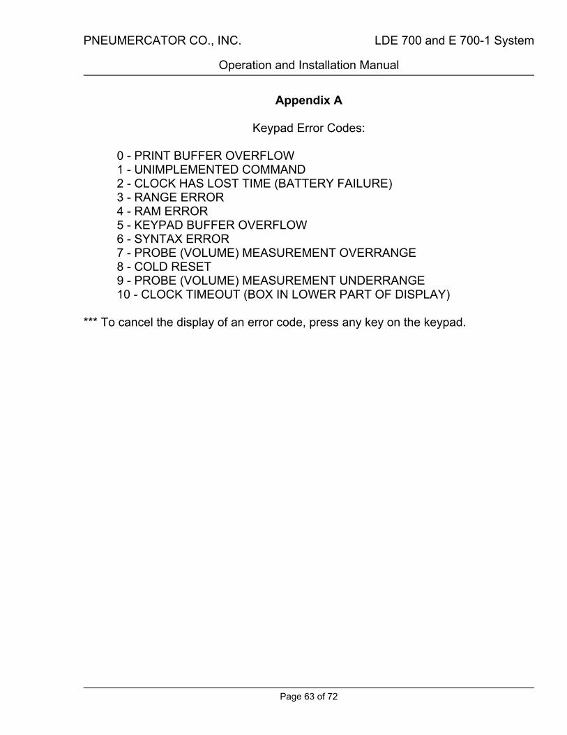
PNEUMERCATOR CO., INC. LDE 700 and E 700-1 System
Operation and Installation Manual
Page 63 of 72
Appendix A
Keypad Error Codes: 0 - PRINT BUFFER OVERFLOW 1 - UNIMPLEMENTED COMMAND 2 - CLOCK HAS LOST TIME (BATTERY FAILURE) 3 - RANGE ERROR 4 - RAM ERROR 5 - KEYPAD BUFFER OVERFLOW 6 - SYNTAX ERROR 7 - PROBE (VOLUME) MEASUREMENT OVERRANGE 8 - COLD RESET 9 - PROBE (VOLUME) MEASUREMENT UNDERRANGE 10 - CLOCK TIMEOUT (BOX IN LOWER PART OF DISPLAY)
*** To cancel the display of an error code, press any key on the keypad.

PNEUMERCATOR CO., INC. LDE 700 and E 700-1 System
Operation and Installation Manual
Page 64 of 72
Appendix B
Tank Product Codes: Product Code Product Name
00 PRODUCT 01 #2 OIL 02 #3 OIL 03 #4 OIL 04 #5 OIL 05 #6 OIL 06 FUEL OIL 07 HEATING OIL 08 DIESEL 09 KEROSENE 10 MOTOR OIL 11 WASTE OIL 12 HYDRAULIC OIL 13 CUTTING OIL 14 QUENCH OIL 15 MINERAL SPIRITS 16 STEERING FLUID 17 TRANSMISSION OIL 18 ATF 19 GASOLINE 20 UNLEADED 21 UNLEADED GASOLINE 22 UNLEADED REGULAR 23 REGULAR UNLEADED 24 UNLEADED PREMIUM 25 PREMIUM UNLEADED 26 UNLEADED SUPER 27 SUPER UNLEADED 28 SUPREME UNLEADED 29 LEAD FREE 30 LEADED 31 LEADED GASOLINE 32 LEADED REGULAR 33 REGULAR LEADED 34 LEADED PREMIUM 35 PREMIUM LEADED

PNEUMERCATOR CO., INC. LDE 700 and E 700-1 System
Operation and Installation Manual
Page 65 of 72
36 LEADED SUPER 37 SUPER LEADED 38 REGULAR 39 PREMIUM 40 SUPER 41 GASOHOL 42 METHANOL 43 METHANOL BLEND 44 ALCOHOL 45 ANTIFREEZE 46 GLYCOL 47 ACETONE 48 TOLUENE 49 MEK 50 SOLVENT 51 WASTE PRODUCT 52 WASTE WATER 53 WATER 54 AV GAS 55 JET FUEL 56 JET A 57 JP-4 58 JP-5 59 JP-6 60 JP-8 61 SPECIAL 62 ETHANOL 63 TANK CONTENTS

PNEUMERCATOR CO., INC. LDE 700 and E 700-1 System
Operation and Installation Manual
Page 66 of 72

PNEUMERCATOR CO., INC. LDE 700 and E 700-1 System
Operation and Installation Manual
Page 67 of 72
Appendix C
RS-232 Connector Pinouts:
DB-25 Connector pin Signal 1 Protective Ground 2 TxD 3 RxD 4 RTS 5 CTS 7 Signal Ground 20 DTR
NOTE DTR is actively pulled to a true state.
If DTR is not used, it may be left unconnected. TxD Transmitted data RxD Received data RTS Request to Send CTS Clear to Send DTR Data Terminal Ready

PNEUMERCATOR CO., INC. LDE 700 and E 700-1 System
Operation and Installation Manual
Page 68 of 72

PNEUMERCATOR CO., INC. LDE 700 and E 700-1 System
Operation and Installation Manual
Page 69 of 72
Appendix D
RS-232 Setup: **** Baud rate changes must be entered from LDE 700 keypad
Baud Rates 300 (default) 1200 2400 4800 9600 Word Length 7 bits Parity Even Parity Stop Bits 1 Stop Bit

PNEUMERCATOR CO., INC. LDE 700 and E 700-1 System
Operation and Installation Manual
Page 70 of 72

PNEUMERCATOR CO., INC. LDE 700 and E 700-1 System
Operation and Installation Manual
Page 71 of 72
Warranty
We warrant that our equipment, if installed according to instructions will be free from defects in material and workmanship for a period of one (1) year following the date of original shipment by Pneumercator. Our liability under this warranty shall be limited to, at our option, (i) repair of the defective equipment, (ii) replacement of the original equipment with
new equipment, or (iii) refund of the original purchase price; and, we shall not be liable for any labor, other installation costs, indirect or consequential damages, or other damages in connection with such equipment. This constitutes our obligation and none other stated for any purpose except the above shall apply.
rev031793

Distributed by:
Pneumercator Co. 1785 Expressway Drive North,
Hauppauge, NY 11788 TEL (631) 293-8450 • FAX: (631) 293-8533
http://www.pneumercator.com
PNEUMERCATORLiquid Level Control Systems