series 751 firelock alarm check valve - energie … victaulic ® series 751 alarm check valve works...
TRANSCRIPT

R
IPS CARBON STEEL PIPE – FIRE PROTECTION PRODUCTS
VICTAULIC
®
IS AN ISO 9001 CERTIFIED COMPANY
® REGISTERED TRADEMARK OF VICTAULIC – © COPYRIGHT 2004 VICTAULIC – PRINTED IN U.S.A. – SKU #WCAS-678K5Q 2218 REV G
30.01
Victaulic Company of America • Phone: 1-800-PICK-VIC (1-800-742-5842) • Fax: 610-250-8817 • e-mail: [email protected] Company of Canada • Phone: 905-884-7444 • Fax: 905-884-9774 • e-mail: [email protected] Europe • Phone:32-9-381-1500 • Fax: 32-9-380-4438 • e-mail: [email protected] America Latina • Phone: 610-559-3300 • Fax: 610-559-3608 • e-mail: [email protected] Asia Pacific • Phone: 86-21-58855151 • Fax: 86-21-58851298 • e-mail: [email protected]
Series 751 FireLock
®
Alarm Check Valve
Grooved X Groovedand Flanged X Grooved
PRODUCT DESCRIPTION
The Victaulic
®
Series 751 alarm check valve works as a check valve by preventing the reverse flow of water from the system piping to the water supply. The valve is trimmed with a water bypass line, which has an in-line swing check valve. The bypass line allows pressure surges to enter the system and to be trapped above the alarm check valve’s clapper without the clapper lifting and causing false alarms.
When a significant flow of water occurs, such as from an open sprinkler, the alarm valve’s clapper lifts and allows water to enter the system. Simultaneously, water enters an intermediate chamber, which allows the water to activate an alarm either through a water motor alarm or through a water pressure alarm. These alarms continue to sound until the flow of water is stopped.
The Victaulic Series 751 alarm check valve is made from high strength, low weight ductile iron, and offers easy access to all internal parts. All internal parts are replaceable without having to remove the valve from the installed position. The rubber clapper seal is easily replaced without removing the clapper from the valve. The valve is painted inside and out to increase corrosion resistance.
The valve can be installed in either the vertical or horizontal orientations, and it can be used in both constant and variable pressure systems when the optional retard chamber is included in the trim piping.
The Series 751 is available 1
1
/
2
- 8" grooved X grooved or 4 - 8" (100 - 200 mm) flanged X grooved. Standard grooved dimensions conform to ANSI/AWWA C606 and standard flanged dimensions conform to ANSI B16.5, Class 150.
The 1
1
/
2
- 6" (40 - 165,1 mm) valve is rated to 300 psi (2065 kPa) and is tested hydrostatically to 600 psi (4135 kPa). The 8" (200 mm) valve is rated to 225 psi (1550 kPa) and is tested hydrostatically to 450 psi (3100 kPa).
Options
Optional equipment includes pressure switch, which allows the activation of an electric alarm panel or remote alarm. The valve can be used in both constant pressure and variable pressure installations with the optional retard chamber. The body is tapped for main drain and all available trim configurations. The trim includes an alarm test valve, which allows testing of the alarm system without reducing the system pressure. Series 751 can be purchased with separate trim kits, or it can be pre-trimmed in either the vertical or horizontal configurations.
ULCUL®
FM
See Victaulicpublication 10.01
for details.
Clapper
AlarmOutlet
AlarmTest
Seat
Exaggerated for clarity
2 Series 751 FireLock
®
Alarm Check Valve
30.01
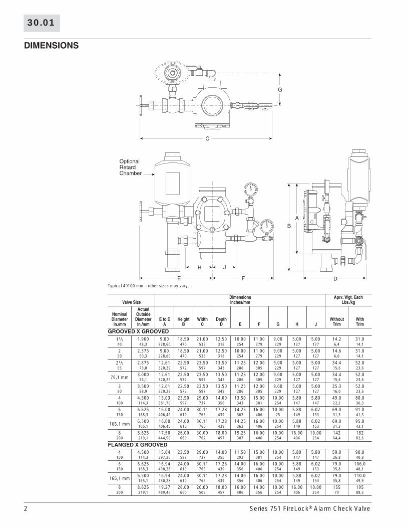
DIMENSIONS
Typical 4"/100 mm – other sizes may vary.
Valve SizeDimensionsInches/mm
Aprx. Wgt. EachLbs./kg
NominalDiameterIn./mm
ActualOutside DiameterIn./mm
E to EA
HeightB
WidthC
DepthD E F G H J
WithoutTrim
WithTrim
GROOVED X GROOVED
1
1
/
2
1.900 9.00 18.50 21.00 12.50 10.00 11.00 9.00 5.00 5.00 14.2 31.0
40 48,3 228,60 470 533 318 254 279 229 127 127 6,4 14,1
2 2.375 9.00 18.50 21.00 12.50 10.00 11.00 9.00 5.00 5.00 14.6 31.0
50 60,3 228,60 470 533 318 254 279 229 127 127 6,6 14,1
2
1
/
2
2.875 12.61 22.50 23.50 13.50 11.25 12.00 9.00 5.00 5.00 34.4 52.0
65 73,0 320,29 572 597 343 286 305 229 127 127 15,6 23,6
76,1 mm 3.000 12.61 22.50 23.50 13.50 11.25 12.00 9.00 5.00 5.00 34.4 52.0
76,1 320,29 572 597 343 286 305 229 127 127 15,6 23,6
3 3.500 12.61 22.50 23.50 13.50 11.25 12.00 9.00 5.00 5.00 35.3 52.0
80 88,9 320,29 572 597 343 286 305 229 127 127 16,0 23,6
4 4.500 15.03 23.50 29.00 14.00 13.50 15.00 10.00 5.80 5.80 49.0 80.0
100 114,3 381,76 597 737 356 343 381 254 147 147 22,2 36,3
6 6.625 16.00 24.00 30.11 17.28 14.25 16.00 10.00 5.88 6.02 69.0 91.0
150 168,3 406,40 610 765 439 362 406 25 149 153 31,3 41,3
165,1 mm 6.500 16.00 24.00 30.11 17.28 14.25 16.00 10.00 5.88 6.02 69.0 95.0
165,1 406,40 610 765 439 362 406 254 149 153 31,3 43,1
8 8.625 17.50 26.00 30.00 18.00 15.25 16.00 10.00 16.00 10.00 142 182
200 219,1 444,50 660 762 457 387 406 254 406 254 64,4 82,6
FLANGED X GROOVED
4 4.500 15.64 23.50 29.00 14.00 11.50 15.00 10.00 5.80 5.80 59.0 90.0
100 114,3 397,26 597 737 355 292 381 254 147 147 26,8 40,8
6 6.625 16.94 24.00 30.11 17.28 14.00 16.00 10.00 5.88 6.02 79.0 106.0
150 168,3 430,28 610 765 439 356 406 254 149 153 35,8 48,1
165,1 mm 6.500 16.94 24.00 30.11 17.28 14.00 16.00 10.00 5.88 6.02 79.0 110.0
165,1 430,28 610 765 439 356 406 254 149 153 35,8 49,9
8 8.625 19.27 26.00 20.00 18.00 16.00 14.00 10.00 16.00 10.00 155 195
200 219,1 489,46 660 508 457 406 356 254 406 254 70 88,5
G
C
E F
JH
A
B
D
OptionalRetardChamber
30.01
Series 751 FireLock
®
Alarm Check Valve 3
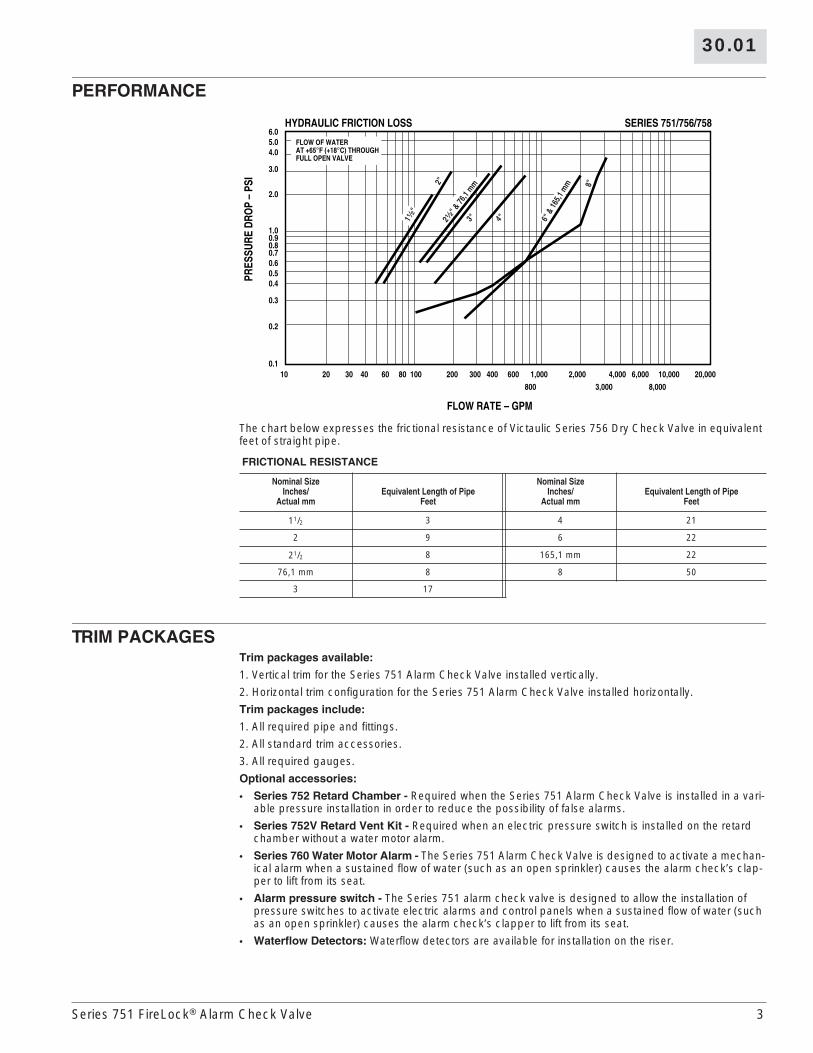
PERFORMANCE
The chart below expresses the frictional resistance of Victaulic Series 756 Dry Check Valve in equivalent feet of straight pipe.
TRIM PACKAGES
Trim packages available:
1. Vertical trim for the Series 751 Alarm Check Valve installed vertically.
2. Horizontal trim configuration for the Series 751 Alarm Check Valve installed horizontally.
Trim packages include:
1. All required pipe and fittings.
2. All standard trim accessories.
3. All required gauges.
Optional accessories:
•
Series 752 Retard
Chamber -
Required when the Series 751 Alarm Check Valve is installed in a vari-able pressure installation in order to reduce the possibility of false alarms.
•
Series 752V Retard Vent Kit -
Required when an electric pressure switch is installed on the retard chamber without a water motor alarm.
•
Series 760 Water Motor Alarm -
The Series 751 Alarm Check Valve is designed to activate a mechan-ical alarm when a sustained flow of water (such as an open sprinkler) causes the alarm check’s clap-per to lift from its seat.
•
Alarm pressure switch -
The Series 751 alarm check valve is designed to allow the installation of pressure switches to activate electric alarms and control panels when a sustained flow of water (such as an open sprinkler) causes the alarm check’s clapper to lift from its seat.
•
Waterflow Detectors:
Waterflow detectors are available for installation on the riser.
FRICTIONAL RESISTANCE
Nominal SizeInches/
Actual mmEquivalent Length of Pipe
Feet
Nominal SizeInches/
Actual mmEquivalent Length of Pipe
Feet
1
1
/
2
3 4 21
2 9 6 22
2
1
/
2
8 165,1 mm 22
76,1 mm 8 8 50
3 17
800 3,000 8,000
6.05.04.0
3.0
2.0
1.00.90.80.70.60.50.4
0.3
0.2
0.1
PRES
SURE
DRO
P–
PSI
10 20 30 40 60 80 100 200 300 400 600 1,000 2,000 4,000 6,000 10,000 20,000
FLOW RATE – GPM
SERIES 751/756/758HYDRAULIC FRICTION LOSS
FLOW OF WATERAT +65°F (+18°C) THROUGHFULL OPEN VALVE
1¹⁄₂"
2"
3" 4" 6" &
165,1
mm
2¹⁄₂"
& 76
,1 mm 8"
4 Series 751 FireLock
®
Alarm Check Valve
30.01
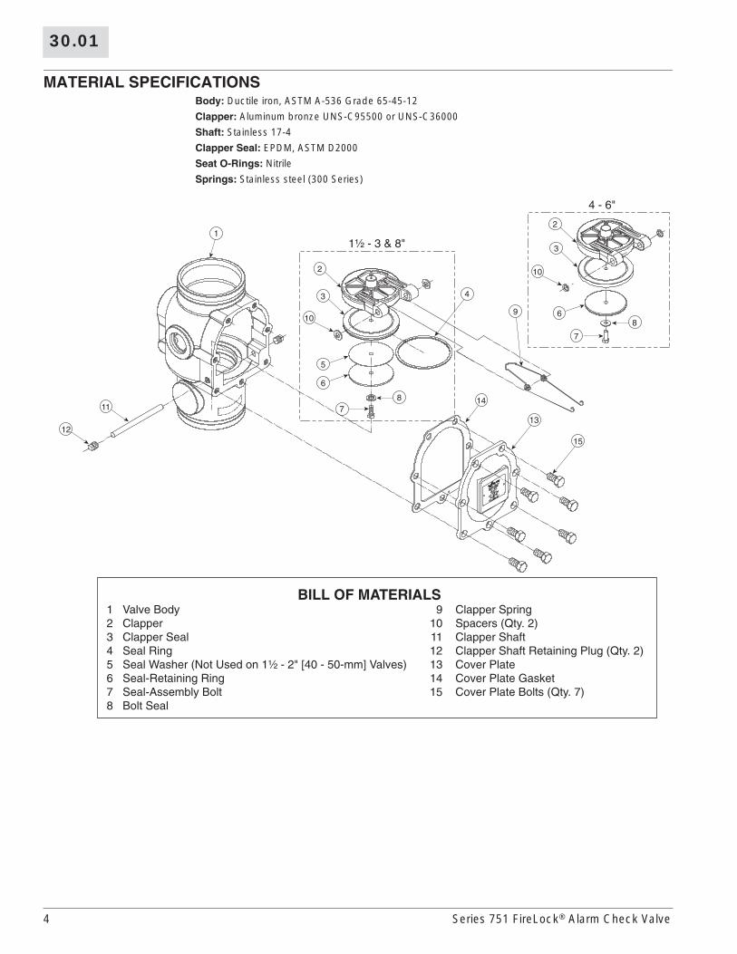
MATERIAL SPECIFICATIONS
Body:
Ductile iron, ASTM A-536 Grade 65-45-12
Clapper:
Aluminum bronze UNS-C95500 or UNS-C36000
Shaft:
Stainless 17-4
Clapper Seal:
EPDM, ASTM D2000
Seat O-Rings:
Nitrile
Springs:
Stainless steel (300 Series)
1¹⁄₂ - 3 & 8"
4 - 6"
1
12
11
9
43
2
10
7
6
5
8 14
13
15
BILL OF MATERIALS 1 Valve Body 9 Clapper Spring 2 Clapper 10 Spacers (Qty. 2) 3 Clapper Seal 11 Clapper Shaft 4 Seal Ring 12 Clapper Shaft Retaining Plug (Qty. 2) 5 Seal Washer (Not Used on 1¹⁄₂ - 2" [40 - 50-mm] Valves) 13 Cover Plate 6 Seal-Retaining Ring 14 Cover Plate Gasket 7 Seal-Assembly Bolt 15 Cover Plate Bolts (Qty. 7) 8 Bolt Seal
3
2
10
7
68

30.01
Series 751 FireLock
®
Alarm Check Valve 5
PARTS
With Vertical TrimGrooved X Grooved
WATER MOTORALARM
SERIES 760
150
F
³⁄₄
ULC
FM
LISTED
To Drain
To Drain
9
10
7
6
13
12
8
11
2
31
5
14
4
BILL OF MATERIALS 1 Series 751 FireLock Alarm Check Valve 8 System s Main Drain Valve 2 Water Supply Pressure Gauge (0-300 psi/0-2068 kPa) 9 Series 752 Retard Chamber (Optional) 3 Swing Check Valve 10 Series 760 Water Motor Alarm (Optional) 4 System Pressure Gauge (0-300 psi/0-2068 kPa) 11 Series 705W Butterfly Valve (Optional) 5 Alarm Line Ball Valve (NO) 12 Style 005 FireLock Rigid Coupling (Optional) 6 Alarm Test Line Ball Valve (NC) 13 PS10-1 or PS10-2 Alarm Pressure Switch 7 Alarm Line Drain Restrictor (¹⁄₁₆-inch) 14 Series 752V Retard Vent Kit (Optional)*
Optional Series 752VRetard Vent Kit
To Water MotorAlarm or Optional
Restrictor
Optional PressureSwitch
Pipe toOpen Drain
NO = Normally Open; NC = Normally Closed* The Series 752V Retard Vent Kit is required any time an air break is needed above the retard chamber. In addition, the Series 752V Retard Vent Kit is required if multiple valves are tied into one water motor alarm and a check valve isolates each line.
Flanged ✕ Grooved
6 Series 751 FireLock
®
Alarm Check Valve
30.01
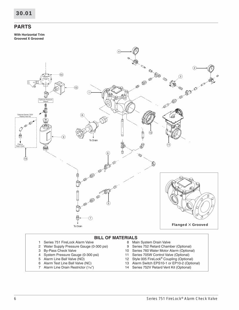
PARTS
With Horizontal TrimGrooved X Grooved
WATER MOTORALARM
SERIES 760
150
F
³⁄₄
ULC
FM
LISTED
To Drain
To Drain
9
5
7
8
1
3
4
2
14
6
10
13
12
11
BILL OF MATERIALS1 Series 751 FireLock Alarm Valve 8 Main System Drain Valve2 Water Supply Pressure Gauge (0-300 psi) 9 Series 752 Retard Chamber (Optional)3 By-Pass Check Valve 10 Series 760 Water Motor Alarm (Optional)4 System Pressure Gauge (0-300 psi) 11 Series 705W Control Valve (Optional)5 Alarm Line Ball Valve (NO) 12 Style 005 FireLock® Coupling (Optional)6 Alarm Test Line Ball Valve (NC) 13 Alarm Switch EPS10-1 or EP10-2 (Optional)7 Alarm Line Drain Restrictor (¹⁄₁₆") 14 Series 752V Retard Vent Kit (Optional)
Optional Series 752VRetard Vent Kit
Optional PressureSwitch
Pipe toOpen Drain
Flanged ✕ Grooved
30.01
Series 751 FireLock
®
Alarm Check Valve 7
PARTS
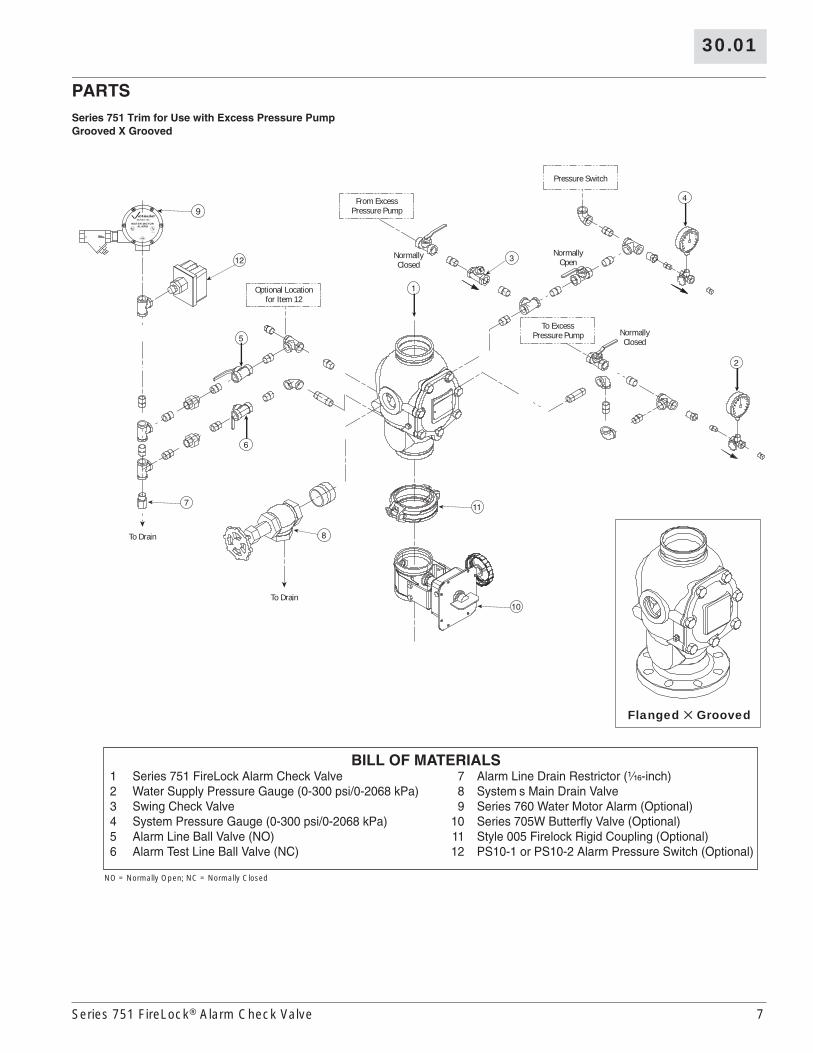
Series 751 Trim for Use with Excess Pressure PumpGrooved X Grooved
12
7
6
11
10
8
2
4
1
5
3
BILL OF MATERIALS1 Series 751 FireLock Alarm Check Valve 7 Alarm Line Drain Restrictor (¹⁄₁₆-inch)2 Water Supply Pressure Gauge (0-300 psi/0-2068 kPa) 8 System s Main Drain Valve3 Swing Check Valve 9 Series 760 Water Motor Alarm (Optional)4 System Pressure Gauge (0-300 psi/0-2068 kPa) 10 Series 705W Butterfly Valve (Optional)5 Alarm Line Ball Valve (NO) 11 Style 005 Firelock Rigid Coupling (Optional)6 Alarm Test Line Ball Valve (NC) 12 PS10-1 or PS10-2 Alarm Pressure Switch (Optional)
NormallyOpen
NormallyClosed
NormallyClosed
To Drain
To Drain
Pressure Switch
Optional Locationfor Item 12
From ExcessPressure Pump
To ExcessPressure Pump
WATER MOTORALARM
SERIES 760
150
F
³⁄₄
ULC
FM
LISTED
9
NO = Normally Open; NC = Normally Closed
Flanged ✕ Grooved

8 Series 751 FireLock
®
Alarm Check Valve
30.01
OPERATION
The Series 751 Alarm Check Valve’s construction includes a clapper, which has a replaceable rubber face. The clapper closure is assisted by a spring, which ensures proper contact of the clapper to the brass seat ring.
When installed, the alarm check valve traps pressure above the clapper and prevents the reverse flow of water. Minor pressure surges pass through the bypass loop without lifting the clapper from its seat. The swing check valve in the bypass line traps the pressure above the clapper; this can be observed in the pressure gauges. The system-side water pressure will always be equal to or greater than the supply-side water pressure in the absence of an open sprinkler.
When a sustained flow of water occurs, such as an activated sprinkler or an open inspector’s test connection, the clapper lifts from its closed position; this allows water to enter the intermediate chamber through the holes in the seat ring. The water flows from the intermediate chamber to the alarm line and activates the system’s alarms. These alarms continue to sound until the flow of water stops.
Operation with an Installed Retard Chamber
When the Series 751 Alarm Check Valve is installed with the optional retard chamber, a surge of water, greater than what the bypass line can handle, will lift the clapper. When the clapper lifts, water will enter the intermediate chamber through the holes in the seat ring, and it will fill the retard chamber. The water then drains from the retard chamber through a restricted orifice.
A sustained flow of water, as in an open sprinkler, will lift the clapper. Water will flow into the intermediate chamber, and it will fill the retard chamber completely; these events activate the water motor alarm and/or the pressure switch for the electric alarm.
WARNING
• This product must be installed by an experienced, trained installer, in accordance with the instructions provided with each valve. These instructions contain important information.
Failure to follow these instructions may result in serious personal injury, property damage, or valve leakage.If you need additional copies of this product literature or the valve installation instructions, or if you have any questions about the safe installation and use of this device, contact Victaulic Company, P.O. Box 31, Easton, PA 18044-0031 USA, Telephone: 001-610-559-3300.
This product shall be manufactured by Victaulic Company. All products to be installed in accordance with current Victaulic installation/assembly instructions.Victaulic reserves the right to change product specifications, designs and standard equipment without notice and without incurring obligations.