series 5400 - microframe corporation 5400 installation & specification guide item no: a5400-7019...
TRANSCRIPT
SERIES 5400
INSTALLATION & SPECIFICATION GUIDE
ITEM NO: A5400-7019
REVISION DATE: 11/09
Microframe Corporation
604 S. 12th Street
Broken Arrow, OK 74012
Tel: (918) 258-4839
Toll Free: 1-800-635-3811
Website: www.microframecorp.com
E-mail: [email protected]
A5400-7019
*A5400-7019*
Microframe Corporation
P.O. Box 1700
Broken Arrow, OK 74013
1-800-635-3811
Limited Warranty Agreement
Your Microframe System is warranted against failure due to
defects in workmanship or material for a period of one (1) year
from the date of purchase. Microframe Corporation will repair
or replace any defective unit. Obvious abuse or mishandling of
the unit is NOT covered by this warranty.
Merchandise Return
If your Unit does not work satisfactorily, please give us a call.
We may be able to clear up the problem by phone. If it becomes
necessary to return your Unit to the factory, please observe the
following:
1. Place Unit in a sturdy box with suffi cient packing mate-
rial.
2. If requested, include the AC power adapter. It is not necessary
to return the cable and connectors unless they are the problem.
3. Return the system insured and prepaid since we are not
responsible for shipping damages and losses on returned Units.
Warranty Service
For warranty service, please contact Microframe toll-free at
(800) 635-3811. A technician will gladly assist you.
Assistance
For any product assistance or maintenance help, contact
Microframe by either calling 1-800-635-3811 or e-mailing us
at: [email protected].
Safety
Do not install substitute parts or perform any modifi cation to
the product without fi rst contacting Microframe.
Warning
All power adapters, line cords, and electrical equipment
should be kept out of the reach of children and away from water.
(If you are installing cable in an air plenum area, such as a drop
ceiling used for air return, you must use plenum-rated cable. The
cable supplied from Microframe is rated CL2 and is approved for
installation everywhere indoors except plenum areas.)
Life Support Policy
Microframe's products are not authorized for use as com-
ponents in life support devices or systems without the express
written approval of the president of Microframe Corporation.
As used herein:
1. Life support devices or systems are defi ned as systems
which support or sustain life, and whose failure to perform when
properly used in accordance with instructions for use provided in
the labeling, can be reasonably expected to result in a signifi cant
injury to the user or any one depending on the system.
2. A critical component is any component of a life support
device or system whose failure to perform can be reasonably
expected to cause the failure of the life support device or system,
or to affect its safety or effectiveness.
Disclaimer
We are constantly striving to improve our products. Due to
this, specifi cations are subject to change without notice.

Table of Contents
How to Use this Manual and the Remote Control ........5
Take-A-Number System Quick Start Instructions ....6
Time-of-Day Clock Quick Start Instructions ...............7
Count Up/Countdown Timer Quick Start Info ...........8
Wiring Diagrams ...........................................................9
Multiple AC Adapter Connection Detail Info ..................10
Optional External Chime Connection Detail Info ..........10
Using Multiple Displays ............................................... 11
Understanding the Programmable Options ................12
Setting the Programmable Options .............................14
Options Table .................................................................15
Multi-Window Service System (MWSS) ..........................16
Model 5400 Specifi cations ...............................................19
Stand-Alone Displays ......................................................19
Timer/Clock Troubleshooting Chart .................................20
General Troubleshooting Chart .......................................20
Take-A-Number Troubleshooting Chart ...........................20
Remote Control Troubleshooting .....................................20
5400 Remote Display Mounting Template .......................21
Microframe Corporation System 5400 General Information
System 5400 General Information
Congratulations on your purchase of the Microframe Model
5400 display. This display can be used as a Take-A-Number/Counter
System, a Clock, or a Count Up/Down Timer.
Manual Organization
Realizing that most users are only interested in one of these
modes, we have made "Quick Start Instructions" for each of the
three applications. Users with only one display per installation
and no special requirements should be able to connect and run
their displays by reading only the "Quick Start" page pertaining
to their application.
Quick Start Sections are as follows:
* Take-A-Number System ------------Page 6
* Time-of-Day Clock ------------------Page 7
* Count Up/Down Timer-------------- Page 8
For more advanced wiring needs, see the "Wiring Diagrams" on
pages 9 and 10.
If you have multiple displays, see "Using Multiple Displays"
on page 11.
To custom-confi gure your displays, see "Understanding the
Programmable Options" on pages 12 and 13 and "Setting the
Programmable Options" on pages 14 and 15.
To understand the advanced Multiple Window Service System,
read the description of "Multi-Window Service System" on pages
16, 17 and 18.
For a spec sheet, see page 19
For troubleshooting needs, see page 20
For mounting templates, see page 21.
Defi nition of Terms
Programming Buttons: These are the three function buttons
on the back of the Model 5400 display designed to program your
system and are labeled Mode, Advance and Increment.
Push Buttons: These are the buttons that you may wire to the
back of the display to control the display's functions.
Remote Control: This is the 'TV' style remote control which
you may purchase as an option with your display to program and/or
operate your system.
Legends
Remote Control Instructions
When reading the programming instructions for the remote
control, the buttons on the remote are enclosed with "quotes" and
items shown on the display are enclosed in (parentheses).
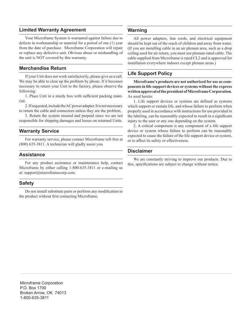
How to Use this Manual and the Remote Control
CLEAR
Remote Control Overview
The following is a summary of the remote control's functional-
ity utilized by this display:
Clear
• resets the number to zero in Take-A-Number (TAN) mode
• resets to zero or reload time in Timer mode
Up/Down
• increment or decrement the current number in TAN mode
• start/stop the timer in timer mode
• go through choices in programming mode
Enter
• accept/enter an entry
Exit
• cancel an entry
• hold for 5 seconds to activate Remote Lockout (see program-
mable option L)
Menu
• puts the display in programming mode.
The system works with most Philips (RC5) remotes.
ENTER
EXIT
UP
DOWN
MENU
NUMERIC
KEYPAD]
Microframe Corporation System 5400 General Information
System 5400 General Information
The 5400 system is preset at the factory to work as a Take-
A-Number system. Simply make the connections as described
below, read the brief operating instructions, and you should be
ready to go.
Installation Instructions
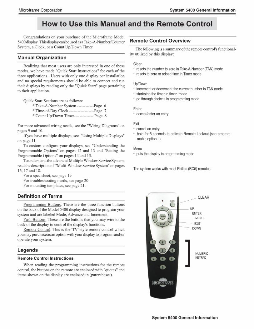
(Please refer to diagram below for further details)
Step 1: Screwdown Connectors
All push button/wire connections to the 5400 Series displays
are made with screwdown terminals located on the back of the
display. To use "screwdown terminals," simply push the stripped
wire into the hole in the side of the connector and then tighten
the screw onto the wire with a screwdriver.
Step 2: Connecting Push Buttons
Typical Take-A-Number systems use push buttons wired to the
display to increment and decrement the "Now Serving" number.
If you have purchased a remote control, you may fi nd that you
do not need these buttons.
To connect the push buttons, connect one wire from each
button under the screwdown terminal labeled "Common." Place
one of the remaining wires under "Input 1" terminal and the
other under "Input 2" (see diagram below). Pushing the button
connected to "Input 1" increments the display, and pushing the
button connected to "Input 2" decrements the display.
Step 3: Connecting Power
Each 5400 Series display includes an AC power adapter. With
the power adapter unplugged from the wall outlet, connect
the wires from the power adapter to the screwdown terminals
labeled "24 VAC."
Step 4: Powering the Display
Plug in the power adapter to an AC outlet. The system should
now be operational.
Take-A-Number System Quick Start Instructions
Step 5: Hanging the Display
The 5400 Series displays hang on the wall like a picture. De-
pending on your installation, you may want to run the wires to the
display in a wall or raceway for aesthetic purposes.
Operating Instructions
Count Up
Push the button wired as the "count up" button or push the
"UP" button on your remote control.
Countdown
Push the button wired as the "countdown" button or push the
"DOWN" button on your remote control.
Quick Set
If you have a remote control, enter the desired number on the
remote and then press the "ENTER" button to accept that number.
If you only have push buttons, push and hold the "Count Up"
button until the 10's digit begins to blink. You may now use the
count up button to change the 10's digit, or continue holding the
button down until the next most signifi cant digit on your display
begins to blink. You can use this method to set all of the digits
on your display.
Reset to Zero
If you are using the remote control, press the "CLEAR" but-
ton to reset the dislays to zero. If you have a "Count Up" and
"Countdown" push button connected, then pushing them both at
the same time will cause the display to reset to all zeros.
Chime
The 5400 Series displays are equipped with an internal chime.
This will sound every time a number is changed. To disable the
chime from a remote control, follow this procedure: Press "Menu"
on the remote. The display will show (-1). Press "UP" until
the display shows (-6) then press "ENTER." The display will
show (00). Press the "UP" button until the display shows (Jx)
where "x" is any number. Press "0" then "ENTER." The chime
is now disabled. If you do not have a remote control, please read
the programming instructions.
115 TO 24 VAC
WALL MOUNTED
TRANSFORMER
CHIMEOPTION
DO
OR
CH
IME
C O R P O R A T I O N
Model 5430 Display
MICROFRAMEINCREMENT SELECT MODE
CO
MM
ON
BA
DO
WN
24
VA
C
UP
485
GN
D
REAR VIEWCO
MM
ON
B A
INP
UT
2
24VA
C
INP
UT
1
485
CO
MM
Count
UP
Count
Down
Microframe Corporation System 5400 General Information
System 5400 General Information
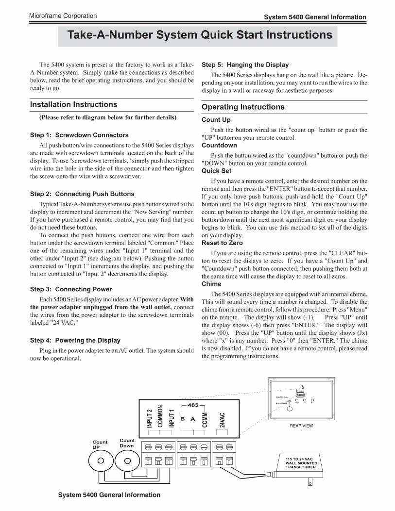
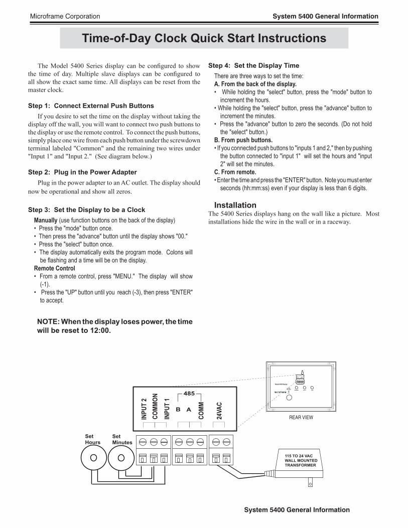
Step 4: Set the Display Time
There are three ways to set the time:
A. From the back of the display.
• While holding the "select" button, press the "mode" button to
increment the hours.
• While holding the "select" button, press the "advance" button to
increment the minutes.
• Press the "advance" button to zero the seconds. (Do not hold
the "select" button.)
B. From push buttons.
• If you connected push buttons to "inputs 1 and 2," then by pushing
the button connected to "input 1" will set the hours and "input
2" will set the minutes.
C. From remote.
• Enter the time and press the "ENTER" button. Note you must enter
seconds (hh:mm:ss) even if your display is less than 6 digits.
InstallationThe 5400 Series displays hang on the wall like a picture. Most
installations hide the wire in the wall or in a raceway.
The Model 5400 Series display can be confi gured to show
the time of day. Multiple slave displays can be confi gured to
all show the exact same time. All displays can be reset from the
master clock.
Step 1: Connect External Push Buttons
If you desire to set the time on the display without taking the
display off the wall, you will want to connect two push buttons to
the display or use the remote control. To connect the push buttons,
simply place one wire from each push button under the screwdown
terminal labeled "Common" and the remaining two wires under
"Input 1" and "Input 2." (See diagram below.)
Step 2: Plug in the Power Adapter
Plug in the power adapter to an AC outlet. The display should
now be operational and show all zeros.
Step 3: Set the Display to be a Clock
Manually (use function buttons on the back of the display)
• Press the "mode" button once.
• Then press the "advance" button until the display shows "00."
• Press the "select" button once.
• The display automatically exits the program mode. Colons will
be fl ashing and a time will be on the display.
Remote Control
• From a remote control, press "MENU." The display will show
(-1).
• Press the "UP" button until you reach (-3), then press "ENTER"
to accept.
NOTE: When the display loses power, the time
will be reset to 12:00.
Time-of-Day Clock Quick Start Instructions
115 TO 24 VAC
WALL MOUNTED
TRANSFORMER
CHIMEOPTION
DO
OR
CH
IME
C O R P O R A T I O N
Model 5430 Display
MICROFRAMEINCREMENT SELECT MODE
CO
MM
ON
BA
DO
WN
24
VA
C
UP
485
GN
D
REAR VIEWCO
MM
ON
B A
INP
UT
2
24V
AC
INP
UT
1
485
CO
MM
Set
Hours
�
Set
Minutes
Microframe Corporation System 5400 General Information
System 5400 General Information
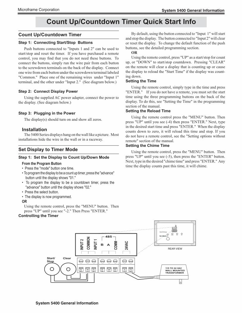
Count Up/Countdown Timer Quick Start Info
By default, using the button connected to "Input 1" will start
and stop the display. The button connected to "Input 2" will clear
or reset the display. To change the default function of the push
buttons, see the detailed programming section.
OR
Using the remote control, press "UP" as a start/stop for count
up, or "DOWN" to start/stop countdown. Pressing "CLEAR"
on the remote will clear a display that is counting up or cause
the display to reload the "Start Time" if the display was count-
ing down.
Setting the Time
Using the remote control, simply type in the time and press
"ENTER." If you do not have a remote, you must set the start
time using the three programming buttons on the back of the
display. To do this, see "Setting the Time" in the programming
section of the manual.
Setting the Reload Time
Using the remote control press the "MENU" button. Then
press "UP" until you see (-4) then press "ENTER." Next, type
in the desired start time and press "ENTER." When the display
counts down to zero, it will reload this time and stop. If you
do not have a remote control, see the "Setting options without
remote" section of the manual.
Setting the Chime Time
Using the remote control, press the "MENU" button. Then
press "UP" until you see (-5), then press the "ENTER" button.
Next, type in the desired "chime time" and press "ENTER." Any
time the display counts past this time, it will chime.
Count Up/Countdown Timer
Step 1: Connecting Start/Stop Buttons
Push buttons connected to "Inputs 1 and 2" can be used to
start/stop and reset the timer. If you have purchased a remote
control, you may fi nd that you do not need these buttons. To
connect the buttons, simply run the wire pair from each button
to the screwdown terminals on the back of the display. Connect
one wire from each button under the screwdown terminal labeled
"Common." Place one of the remaining wires under "Input 1"
terminal, and the other under "Input 2." (See diagram below.)
Step 2: Connect Display Power
Using the supplied AC power adapter, connect the power to
the display. (See diagram below.)
Step 3: Plugging in the Power
The display(s) should turn on and show all zeros.
InstallationThe 5400 Series displays hang on the wall like a picture. Most
installations hide the wire in the wall or in a raceway.
Set Display to Timer Mode
Step 1: Set the Display to Count Up/Down Mode
From the Program Button
• Press the "mode" button one time.
• To program the display to be a count up timer, press the "advance"
button until the display shows "01."
• To program the display to be a countdown timer, press the
"advance" button until the display shows "02."
• Press the select button.
• The display is now programmed.
OR
Using the remote control, press the "MENU" button. Then
press "UP" until you see "-2." Then Press "ENTER."
Controlling the Timer
115 TO 24 VAC
WALL MOUNTED
TRANSFORMER
CHIMEOPTION
DO
OR
CH
IME
C O R P O R A T I O N
Model 5430 Display
MICROFRAMEINCREMENT SELECT MODE
CO
MM
ON
BA
DO
WN
24V
AC
UP
485
GN
D
REAR VIEWCO
MM
ON
B A
INP
UT
2
24VA
C
INP
UT
1
485
CO
MM
Start/
Stop
�
Clear
Microframe Corporation System 5400 General Information
System 5400 General Information
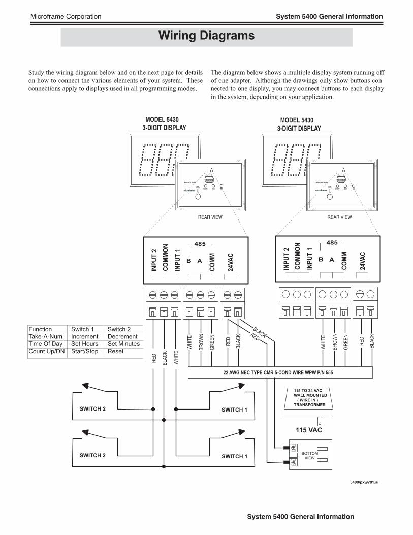
Study the wiring diagram below and on the next page for details
on how to connect the various elements of your system. These
connections apply to displays used in all programming modes.
The diagram below shows a multiple display system running off
of one adapter. Although the drawings only show buttons con-
nected to one display, you may connect buttons to each display
in the system, depending on your application.
Wiring Diagrams
5400\px\9701.ai
115 TO 24 VAC
WALL MOUNTED
( WIRE IN )TRANSFORMER
115 VAC
22 AWG NEC TYPE CMR 5-COND WIRE WPW P/N 555
RE
D
BLA
CK
GR
EE
N
BR
OW
N
WH
ITE RED
BLACK
CHIMEOPTION
DO
OR
CH
IME
C O R P O R A T I O N
Model 5430 Display
MICROFRAMEINCREMENT SELECT MODE
CO
MM
ON
BA
DO
WN
24V
AC
UP
485
GN
D
CHIMEOPTION
DO
OR
CH
IME
C O R P O R A T I O N
Model 5430 Display
MICROFRAMEINCREMENT SELECT MODE
CO
MM
ON
BA
DO
WN
24V
AC
UP
485
GN
D
SWITCH 2 SWITCH 1
SWITCH 2 SWITCH 1
RE
D
BLA
CK
GR
EE
N
BR
OW
N
WH
ITE
MODEL 5430
3-DIGIT DISPLAY MODEL 5430
3-DIGIT DISPLAY
REAR VIEW REAR VIEW
CO
MM
ON
B A
INP
UT
2
24V
AC
INP
UT
1
485
CO
MM
CO
MM
ON
B A
INP
UT
2
24V
AC
INP
UT
1
485
CO
MM
BOTTOM
VIEW
BLA
CK
RE
D
WH
ITE
Function Switch 1 Switch 2
Take-A-Num. Increment Decrement
Time Of Day Set Hours Set Minutes
Count Up/DN Start/Stop Reset
Microframe Corporation System 5400 General Information
System 5400 General Information
5400\px\9705.ai
REAR VIEW
CO
MM
ON
B A
INP
UT
2
24V
AC
INP
UT
1
485
CO
MM
CO
MM
ON
B A
INP
UT
2
24V
AC
INP
UT
1
485
CO
MM
CHIME
OPTION
DO
OR
CH
IME
C O R P O R A T I O N
Model 5440 Display
MICROFRAMEINCREMENT SELECT MODE
CO
MM
ON
BA
DO
WN
24V
AC
UP
485
GN
D
MODEL 5440
4-DIGIT DISPLAY
CHIME
OPTION
DO
OR
CH
IME
C O R P O R A T I O N
Model 5440 Display
MICROFRAMEINCREMENT SELECT MODE
CO
MM
ON
BA
DO
WN
24V
AC
UP
485
GN
D
MODEL 5440
4-DIGIT DISPLAY
REAR VIEW
REAR VIEW
CO
MM
ON
B A
INP
UT
2
24V
AC
INP
UT
1
485
CO
MM
CO
MM
ON
B A
INP
UT
2
24V
AC
INP
UT
1
485
CO
MM
CHIME
OPTION
DO
OR
CH
IME
C O R P O R A T I O N
Model 5440 Display
MICROFRAMEINCREMENT SELECT MODE
CO
MM
ON
BA
DO
WN
24V
AC
UP
485
GN
D
MODEL 5440
4-DIGIT DISPLAY
CHIME
OPTION
DO
OR
CH
IME
C O R P O R A T I O N
Model 5440 Display
MICROFRAMEINCREMENT SELECT MODE
CO
MM
ON
BA
DO
WN
24V
AC
UP
485
GN
D
MODEL 5440
4-DIGIT DISPLAY
REAR VIEW
RE
D
BL
AC
K
115 TO 24 VAC
WALL MOUNTED
TRANSFORMER
115 VAC
RED
BLACK
RE
D
BL
AC
K
POWER CABLE
RE
D
BL
AC
K
115 TO 24 VAC
WALL MOUNTED
TRANSFORMER
115 VAC
RED
BLACK
RE
D
BL
AC
K
POWER CABLE
22 AWG 3-Conductor Wire
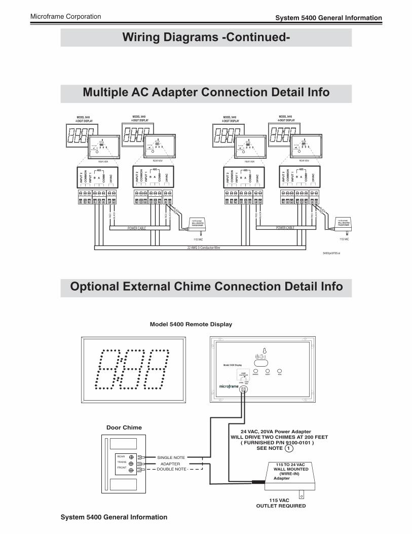
Model 5400 Remote Display
REAR
TRANS
FRONT
Door Chime
DOUBLE NOTE
SINGLE NOTE
ADAPTER 115 TO 24 VACWALL MOUNTED (WIRE-IN)Adapter
115 VACOUTLET REQUIRED
24 VAC, 20VA Power AdapterWILL DRIVE TWO CHIMES AT 200 FEET ( FURNISHED P/N 9100-0101 ) SEE NOTE 1
CO
MM
ON
B AINP
UT
2
24VA
C
INP
UT
1 485
CO
M
Model 5430 Display
C O R P O R A T I O N
MICROFRAME
ADVANCE SELECT MODE CHIME
CONTROLER
24VAC
MAXCHIME
Multiple AC Adapter Connection Detail Info
Optional External Chime Connection Detail Info
Wiring Diagrams -Continued-
Microframe Corporation System 5400 General Information
System 5400 General Information
Using Multiple Displays
Introduction
The 5400 Series displays have been designed to be capable of
working together in large systems. The electrical connections for
multiple displays have been shown in the wiring diagrams on the
previous pages which is the same for connecting multiple displays,
regardless of the application.
Depending on your application, you may have to set the mode
of additional displays to operate as "slaves." The specifi cs for using
multiple displays with each mode are outlined below.
Take-A-Number System (Standard)
To have multiple displays all showing the same number in a
Take-A-Number system, simply connect the displays as shown in
the electrical connection diagrams. You may wire push buttons to
any of the displays in the system. Pushing the buttons connected
to any of the displays will cause the numbers to change on all of
the displays. No programming is necessary for this option.
Time-of-Day Clock and
Count Up/Down Timers
To use multiple displays with these systems, you will need to
set one display in the system to either a Clock (as outlined in the
"Clock Quick Start" instructions) or a timer (as outlined in the
"Timer Quick Start" instructions). All additional displays will
need to be set as "Slaves." To set a display to slave mode, you will
need to use the programming buttons on the back of the display
or the remote control as outlined below. All "slave" displays will
show the same numbers as the master. Remote push buttons
connected to slaves will not function. Only the remote control
or push buttons used on the master display can change the
time on the slave displays.
Set as Slave using Remote Control
From the remote control, press "MENU." The display will
show
(-1). Press "UP" until you reach (-6) then press "ENTER."
The display will show (00). Now press "UP" one time, then type
3, then "ENTER."
Set as Slave using Programming Buttons
• Press the "mode" button twice.
• Press the "advance" button until the display shows "13."
• Press and hold the "mode" button until the display returns to
normal. Colons will begin to fl ash.
Multi-Window Service System
A Multi-Window Service System is basically a Take-A-Num-
ber system with the ability to have displays over multiple service
counters. Each service counter display can show the number of
the customer that is actually being served rather than the highest
number. Because this is a complex confi guration, there is an entire
section of the manual dedicated to this topic. Please see "Multi-
Window Service Systems" for further information.
Microframe Corporation System 5400 General Information
System 5400 General Information
Understanding the Programmable Options
Introduction
Customers with standard Take-A-Number, Clock or Count
Up/Down systems will not need to read this section of the manual.
All of the programming for 90 percent of the applications are
specifi ed on the quick start pages for the particular application.
This section should be read by those customers desiring to change
the standard behavior of the display or to utilize the advanced
features of the display. The fi rst step in programming the displays
is understanding the programmable options. This section will
include a defi nition of what each option will do. The fi nal step is
to understand how to set the features on the display (see "Setting
the Programmable Options").
Organization
The memory for the 5400 Series displays is organized into
"areas." The "areas" are numbered 1- 9 and then A-J. Each "area"
contains a 1-digit value from 0 - 9. For instance, "area B" could be
set to 4. The 5400 display looks at the values stored in its memory
to determine its behavior. In the following pages, the meaning of
the values stored in each area will be discussed in detail as they
pertain to each of the three modes (Take-A-Number, Clock and
Timer). In addition to these memory locations, areas U,V and Y
are used to store 6-digit times for purposes discussed below.
It makes the most sense to study the memory locations or-
ganized by functions as seen below. To view memory by loca-
tion, see the "Programmable Options Summary Sheet" on the
following pages.
Overall Mode of Display
Area 1 - Mode
The display looks at this area of memory to determine what type
of display it is; i.e. Clock, Take-A-Number, Count Up/Count-
down, etc.
0 - Clock
1 - Count Up Timer
2 - Countdown Timer
3 - Slave Display (Clock or Timer)
4 - MWSS Lobby Master
5 - MWSS Lobby Slave
6 - MWSS window slave auto address
7 - MWSS clerk slave manual address
Button Logic (Affects all Modes)
These options effect how the display "Inputs 1 and 2" respond.
Area 9 - Dry/Voltage Input
0 - If Area 9 is set to a 0, then the push buttons will respond
when the inputs are shorted together. No external voltage should
be applied with the inputs in this state.
1- If Area 9 is set to a 1, then the push buttons will respond
to a TTL level signal between the input and "common."
NOTE: "Common" should be tied to ground.
Area A - Normally Open/Normally Closed
0 - With the value set to zero, the display will assume that the
normal state of the inputs is not shorted together.
1 - With the value set to 1, the display will assume that the
normal state of the inputs is shorted together or +5 volts if Area
9 is set to 1.
Area C - Momentary vs. Continuous
0 - With the value set to zero, the display will expect a momen-
tary contact closure at its inputs; i.e. a doorbell push button.
1 - With the value set to 1, the display will treat the buttons
as "change of state;" i.e. it will trigger an event when the signal
changes from shorted to open and vice versa.
Area L - IR Lockout
0 - Display will ignore the remote (prevents accidental changes
to display in a multi-display installation).
1 - Display will respond to remote.
You may also toggle IR Lockout on/off by pressing and holding
the exit button for 5 seconds. The display will indicate the change
by showing "0ir" or "1ir," where "0"=locked and "1"=normal.
Clock and Timer Features
These options pertain to the Clock or Timer modes of the display
only.
Area 2 - On Roll Over
If the display is counting up and reaches its roll over point (see
range lock), it will either stop or reset to zero and keep counting
depending on this option.
0 - With value set to zero, display will stop.
1 - With value set to 1, display will keep counting from
zero.
Area 3 - On Zero
When the display is being used as a countdown timer and it reaches
zero, it decides what to do based on the value in this area.
0 - Stop
1 - Reload with "Reload" time and stop
2 - Reload with "Reload" time and continue
3 - Begin Counting Up
Area E - Military Time
When set as a clock, the display will look at this area to determine
if military time is active.
0 - 12 Hour Clock mode
1 - 24 Hour Military Time Mode
Area D - Start/Stop Button Logic
This area only affects the external buttons and count up/down
timers. The display looks at the value in this area to determine
what to do the "third" time the button connected to "Input 1" is
pressed. The fi rst time the button is pressed, the display always
starts. The second time the button is pressed, the display always
stops. The third time the button is pressed, the display will either
start again, go to to zero, or reload and start again, or go to zero or
reload and stop. If the display is counting up, it will go to zero.
Microframe Corporation System 5400 General Information
System 5400 General Information
If it is counting down it will reload the reload time.
0 - Zero or Reload and Start
1 - Zero or Reload and Stop
2 - Start/Stop/Start (Factory Default)
Area V - Set Reload Time
This memory area is used to store the 6-digit reload time for
timers. When a timer reaches zero while counting down, it looks
in this area for the time to reload.
Area Y - Set Chime Time
This area stores the 6-digit time value at which the display will
chime. This can be used with count up/down timers to set a chime at
a given point in the count or with a clock to serve as an alarm.
Area 6 - Display Size
The display looks at this area to see how many digits it has. It
is set at the factory to match the number of digits of your display;
i.e. a 3-digit display would have a "3" in this option. The only
reason you would change this value would be to fool the display
into thinking it had a different number of digits than it really had.
You may want to call technical support if your needs are this
complex.
Area 7 - Least Signifi cant Digit Lock
This area sets the smallest time increment that will be shown on
a display; i.e. if you want your 4-digit display to only show hours
and minutes and never seconds, you would set this value to "2."
0 - not used
1 - 4 = Seconds, Minutes, Hours, Days
Area 8 - Most Signifi cant Digit Lock
This area sets the largest increment of time the display will
show: For example, if you want your display to count more then
24 hours but did not want it to roll over to days, you would set
this value to "3" for hours.
0 - Not Used
1 - 4 = Seconds, Minutes, Hours, Days
Area F - Flash Colons
This area allows you to change which colons can be turned
on.
0 - No Colons Flash
1 - Left Colons Flash (6-Digit Display Only)
2 - Right Colons Flash
3 - Both Colons Flash
Area G - Colon Flash Rate
Use this area to control how fast your colons fl ash.
0 - Colons stay on all of the time
1 - Colons fl ash once a second
2 - Colons fl ash twice a second
3 - Colons fl ash four times a second
Take-A-Number Options
Area B - Leading Zero Suppression
The value in this area determines whether or not your display
will show leading zeros; i.e., the difference between seeing "1"
on your display and seeing "000001."
0 - Shows leading zeros
1 - Does not show leading zeros
Area H - Display Address "Tens" Digit
This is used in the Multi-Window Service System confi gura-
tion to set the address of Window Slaves; stores a value from 0-9.
See the Multi-Window Service System section of the manual for
further details.
Area I - Display Address "Ones" Digit
This is used in the Multi-Window Service System confi guration
to set the address of Window Slaves; stores a value from 0-9. See
the Multi-Window Service System for further details.
Chime Options
The display comes standard with an internal chime. In addi-
tion, an external "chime driver" circuit can be purchased at the
time of order. Both the internal chime and the external "chime
driver" activate at the same time. The "chime driver" circuit can
be connected to an external doorbell or other 24VAC device.
For details on the "Chime Driver" circuit, see the "Chime Driver"
specifi cations in this manual. Unless otherwise specifi ed, both
the options below effect both the internal chime and the chime
driver circuit.
Area 4 - Chime on Zero
When the display is used as a countdown clock, it will activate
the chime when it reaches zero based on this value.
0 - Do not activate chime when counting down to zero.
1 - Activate the chime when counting down to zero.
Area 5 - Chime Duration Chime Driver Circuit Only
This area is valid only if you have purchased the optional chime
driver circuit. The display looks at this area of memory to determine
how long to allow the current to fl ow through the external chime
circuit. Values can be set from 0 -9 with each increment adding
0.1 seconds to the value. See the "Programming Area Table" for
a complete listing.
Area J - Internal Chime Options
This area controls the volume and sound of the internal chime.
The single chime is a "Ding-Dong" sound where a double chime
is a "Ding-Dong, Ding-Dong" sound.
0 - Internal Chime Off
1 - Low Volume Single Chime
2 - High Volume Single Chime
3 - Low Volume Double Chime
4 - High Volume Double Chime
Understanding Programmable Options
Microframe Corporation System 5400 General Information
System 5400 General Information
Intro to Setting Options
This section describes how to set the options on the 5400 display.
To understand the function of each option, see "Understanding
Programmable Options."
This page references the table on the next page extensively.
As you look at the table on the next page, you should see four
distinct areas: "Remote Control Quick Set," "Push Button Quick
Set," "Standard Options" and "Push Button Time Set."
The "Quick Set Areas" are used to quickly set all of the other
"standard option" areas in memory to typical application settings.
The "Standard Options" area stores the actual settings for the
display. The "Push Button Time Set" area is used to set the reload
and chime times if you do not have a remote control.
There are two ways to set the options on the display. Please
skip to the section below discussing your method.
Setting the Options with a Remote Control
Pressing the "MENU" button on the remote will access the
programming mode. The "UP/DOWN" buttons will move you
through the areas. Where applicable, the numbers on the remote
will change the values. The "ENTER" button will save the changes
and exit the programming mode.
When you press the "MENU" button on the remote control,
you will see a "-1." This corresponds to the "-1" at the top of the
chart on the next page. Pressing the "UP" button on the remote
will move you through the chart to "-6," and then back to "-1."
Option "-1" through "-3" are used to quickly change the mode
of the display. For instance to change to a clock, simply press
the "ENTER" button with the display showing "-3."
To set the reload time or the chime time, press the "ENTER"
button with either "-4" or "-5" showing on the display. Then
using the numbers on the remote enter a 6-digit time then press
"ENTER" to save.
To set the standard options of the display press the "UP/
DOWN" until you see a "-6" on the display, then press the "EN-
TER" button. You will then see "00" on the display corresponding
to the "00" on the "Push Button Quick Set" on the chart on the
next page. Press the "UP" button to move through the areas in the
standard options. When you fi nd the option you want to change,
type the value using the numbers on the remote; then press the
"ENTER" button to accept the changes and exit programming,
or press the "EXIT" changes to quit without saving.
You will not use the "Push Button Time Set"
with the remote control.
Setting the Programmable Options
Setting the Options Using the Programming
Buttons
(on the back of the display)
To get into programming mode, press the "mode" button. The
display will show "00" corresponding to the "00" in the "Push
Button Quick Set" on the table on the next page. Pressing the
"advance" button will increment the value of a given area. Pressing
the "mode" button will move you through the areas.
When in the "quick set" area, pressing "select" will set all of
the options to the given application type and save and exit the
programming mode.
To change the value of an option in the "standard options area,
press the "mode" button until you reach the desired area. Then
press the "advance" button to change the value of the area. Press
"mode" again to move to another area or press and hold "mode"
to save changes and exit. To exit without saving changes, simply
wait 30 seconds without pushing any buttons.
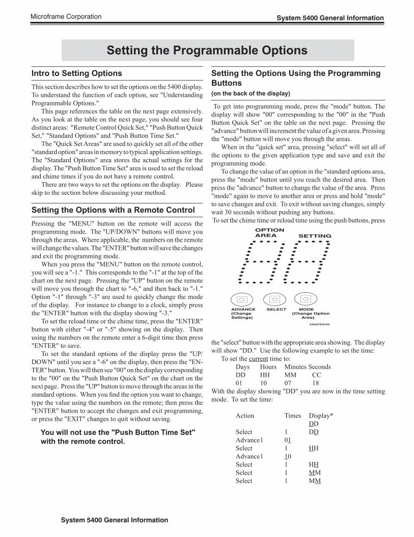
To set the chime time or reload time using the push buttons, press
the "select" button with the appropriate area showing. The display
will show "DD." Use the following example to set the time:
To set the current time to:
Days Hours Minutes Seconds
DD HH MM CC
01 10 07 18
With the display showing "DD" you are now in the time setting
mode. To set the time:
Action Times Display*
DD
Select 1 DD
Advance 1 01
Select 1 HH
Advance 1 10
Select 1 HH
Select 1 MM
Select 1 MM
OPTION
AREA
ADVANCE SELECT MODE
(Change (Change Option
Settings) Area)
5400\PX\9700
SETTING
Microframe Corporation System 5400 General Information
System 5400 General Information
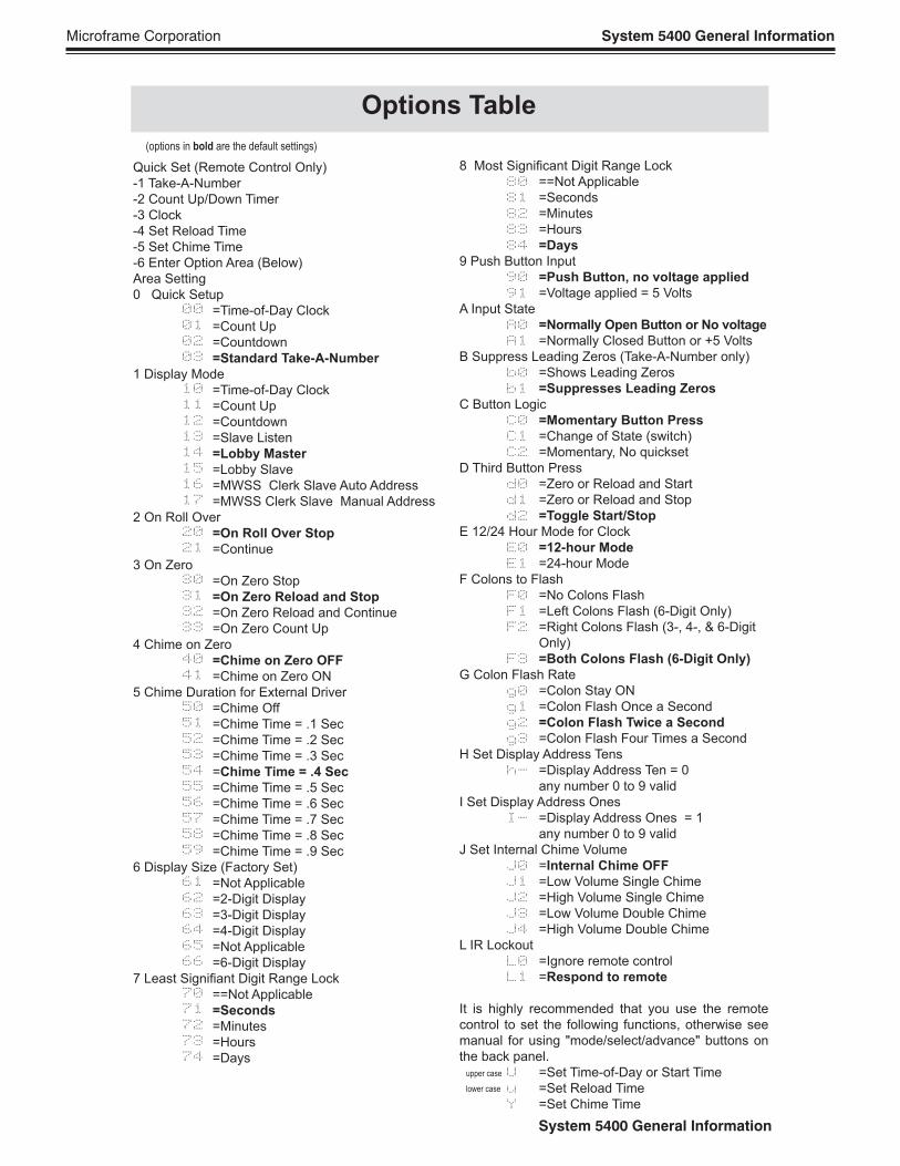
Quick Set (Remote Control Only)
-1 Take-A-Number
-2 Count Up/Down Timer
-3 Clock
-4 Set Reload Time
-5 Set Chime Time
-6 Enter Option Area (Below)
Area Setting
0 Quick Setup
=Time-of-Day Clock
=Count Up
=Countdown
=Standard Take-A-Number
1 Display Mode
=Time-of-Day Clock
=Count Up
=Countdown
=Slave Listen
=Lobby Master
=Lobby Slave
=MWSS Clerk Slave Auto Address
=MWSS Clerk Slave Manual Address
2 On Roll Over
=On Roll Over Stop
=Continue
3 On Zero
=On Zero Stop
=On Zero Reload and Stop
=On Zero Reload and Continue
=On Zero Count Up
4 Chime on Zero
=Chime on Zero OFF
=Chime on Zero ON
5 Chime Duration for External Driver
=Chime Off
=Chime Time = .1 Sec
=Chime Time = .2 Sec
=Chime Time = .3 Sec
=Chime Time = .4 Sec
=Chime Time = .5 Sec
=Chime Time = .6 Sec
=Chime Time = .7 Sec
=Chime Time = .8 Sec
=Chime Time = .9 Sec
6 Display Size (Factory Set)
=Not Applicable
=2-Digit Display
=3-Digit Display
=4-Digit Display
=Not Applicable
=6-Digit Display
7 Least Signifi ant Digit Range Lock
==Not Applicable
=Seconds
=Minutes
=Hours
=Days
8 Most Signifi cant Digit Range Lock
==Not Applicable
=Seconds
=Minutes
=Hours
=Days
9 Push Button Input
=Push Button, no voltage applied
=Voltage applied = 5 Volts
A Input State
=Normally Open Button or No voltage
=Normally Closed Button or +5 Volts
B Suppress Leading Zeros (Take-A-Number only)
=Shows Leading Zeros
=Suppresses Leading Zeros
C Button Logic
=Momentary Button Press
=Change of State (switch)
=Momentary, No quickset
D Third Button Press
=Zero or Reload and Start
=Zero or Reload and Stop
=Toggle Start/Stop
E 12/24 Hour Mode for Clock
=12-hour Mode
=24-hour Mode
F Colons to Flash
=No Colons Flash
=Left Colons Flash (6-Digit Only)
=Right Colons Flash (3-, 4-, & 6-Digit
Only)
=Both Colons Flash (6-Digit Only)
G Colon Flash Rate
=Colon Stay ON
=Colon Flash Once a Second
=Colon Flash Twice a Second
=Colon Flash Four Times a Second
H Set Display Address Tens
=Display Address Ten = 0
any number 0 to 9 valid
I Set Display Address Ones
=Display Address Ones = 1
any number 0 to 9 valid
J Set Internal Chime Volume
=Internal Chime OFF
=Low Volume Single Chime
=High Volume Single Chime
=Low Volume Double Chime
=High Volume Double Chime
L IR Lockout
=Ignore remote control
=Respond to remote
It is highly recommended that you use the remote
control to set the following functions, otherwise see
manual for using "mode/select/advance" buttons on
the back panel.
=Set Time-of-Day or Start Time
=Set Reload Time
=Set Chime Time
00
01
02
03
10
11
12
13
14
15
16
17
20
21
30
31
32
33
40
41
50
51
52
53
54
55
56
57
58
59
61
62
63
64
65
66
70
71
72
73
74
80
81
82
83
84
90
91
A0
A1
b0
b1
C0
C1
C2
d0
d1
d2
E0
E1
F0
F1
F2
F3
g0
g1
g2
g3
h-
I-
J0
J1
J2
J3
J4
L0
L1
U
u
Y
Options Table
upper case
lower case
(options in bold are the default settings)
Microframe Corporation Section 2: Take-A-Number System
Section 2: Take-A-Number System
Multi-Window Service System (MWSS)
System Overview
A Multi-Window Service System is an advanced
Take-A-Number system. In a typical MWSS applica-
tion, there are several clerks at a service counter. All
of the clerks are serving a "pool" of customers with
sequentially numbered tickets. The system can be
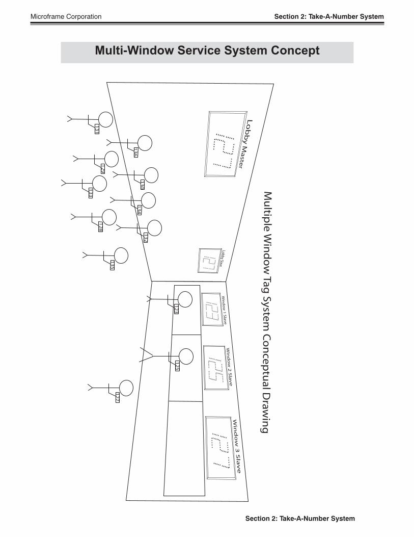
best understood by studying the concept drawing on
the next page.
There are three types of displays shown in the con-
cept drawing. The 5400 Series displays can be set to
any of these types using the programmable options.
Lobby Master
The "Lobby Master" display shows the highest
number being served. There can only be one "Lobby
Master" per system.
Lobby Slave
The "Lobby Slave" displays show the same number
as the "Lobby Master." You can have as many "Lobby
Slaves" as you need.
Window Slave
"Window Slave" displays show the number cur-
rently being serviced by a clerk. You can have as many
"Window Slave" displays as you need. Push buttons
are attached to each window slave display.
System Operation
Push buttons are generally connected to the window
slave displays. When the clerk pushes the button con-
nected to the window slave, the lobby master and lobby
slave displays will increment by one. The window
slave, whose button was pushed, will show the same
number as the lobby master. Other window slaves will
not change. In this way customers in the waiting area
will be able to see that their number is being called
and see which clerk to go to for service.
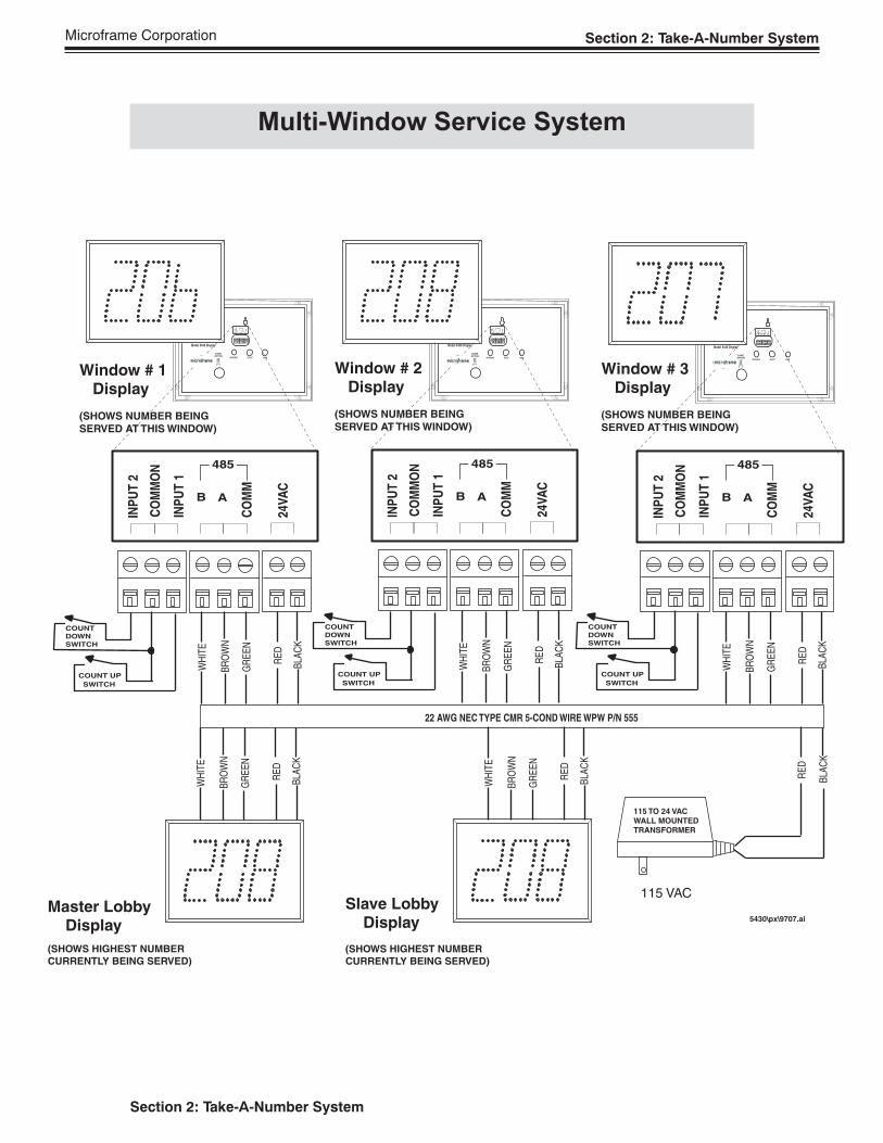
Setting Up the System
To set up a Take-A-Number System, fi rst wire
the system as shown in the "Take-A-Number Wiring
Diagram" on page 18. Next, program the display to
the appropriate value in Area 1. Setting Area 1 to a
4 will cause the display to be a lobby master; setting
Area 1 to a 5 will cause the display to be a lobby slave,
and setting Area 1 to a 6 will cause the display to be a
window slave. See the "Setting Programmable Options"
section for details on how to change these values.
All displays may be hung on the wall like a picture.
See the "Mounting Template" section for easy wire
cutouts when running wire through the wall.
Special Case MWSS
In some cases, it may be necessary to have two
window slave displays showing the same number.
For instance, each service had one display facing the
customer and another display facing the clerk so that
the clerk could see the number they were about to
serve. In this case all of the window slave displays
will have to be set to "MWSS Clerk Slave Manual
Address." This is done by setting Area 1 to a value of
7. In addition, each window slave display will have to
be assigned an "address." This is done by setting the
values of areas "H" and "I." Window slave displays
with the same address will show the same number.
For details on setting the values of these areas, see the
section "Setting the Programmable Options."
Microframe Corporation Section 2: Take-A-Number System
Section 2: Take-A-Number System
Multi-Window Service System Concept
12
7
Mu
ltiple
Win
do
w T
ag
Sy
stem
Co
nc
ep
tua
l Dra
win
g
12
51
23
13
2
13
41
30
13
6
13
5
12
8
13
3
12
9
13
1
Microframe Corporation Section 2: Take-A-Number System
Section 2: Take-A-Number System
Multi-Window Service System
5430\px\9707.ai
115 TO 24 VAC
WALL MOUNTED
TRANSFORMER
115 VAC
RE
D
BLA
CK
22 AWG NEC TYPE CMR 5-COND WIRE WPW P/N 555
RE
D
BLA
CK
GR
EE
N
BR
OW
N
WH
ITE
RE
D
BLA
CK
GR
EE
N
BR
OW
N
WH
ITE
RE
D
BLA
CK
GR
EE
N
BR
OW
N
WH
ITE
CO
MM
ON
B A
INP
UT
2
24V
AC
INP
UT
1
485
CO
MM
CO
MM
ON
B A
INP
UT
2
24V
AC
INP
UT
1
485
CO
MM
CO
MM
ON
B A
INP
UT
2
24V
AC
INP
UT
1
485
CO
MM
COUNT
DOWN
SWITCH
COUNT UP
SWITCH
CHIME
OPTION
DO
OR
C
HIM
E
C O R P O R A T I O N
Model 5430 Display
MICROFRAMEINCREMENT SELECT MODE
CO
MM
ON
BA
DO
WN
24
VA
C
UP
485
GN
D
CHIME
OPTION
DO
OR
C
HIM
E
C O R P O R A T I O N
Model 5430 Display
MICROFRAMEINCREMENT SELECT MODE
CO
MM
ON
BA
DO
WN
24
VA
C
UP
485
GN
D
CHIME
OPTION
DO
OR
C
HIM
E
C O R P O R A T I O N
Model 5430 Display
MICROFRAMEINCREMENT SELECT MODE
CO
MM
ON
BA
DO
WN
24
VA
C
UP
485
GN
D
COUNT
DOWN
SWITCH
COUNT UP
SWITCH
COUNT
DOWN
SWITCH
COUNT UP
SWITCH
RE
D
BLA
CK
GR
EE
N
BR
OW
N
WH
ITE
Master Lobby Display
(SHOWS HIGHEST NUMBER
CURRENTLY BEING SERVED)
Window # 1 Display
(SHOWS NUMBER BEING
SERVED AT THIS WINDOW)
Window # 2 Display
(SHOWS NUMBER BEING
SERVED AT THIS WINDOW)
Window # 3 Display
(SHOWS NUMBER BEING
SERVED AT THIS WINDOW)
RE
D
BLA
CK
GR
EE
N
BR
OW
N
WH
ITE
Slave Lobby Display
(SHOWS HIGHEST NUMBER
CURRENTLY BEING SERVED)
Microframe Corporation System 5400 General Information
System 5400 General Information
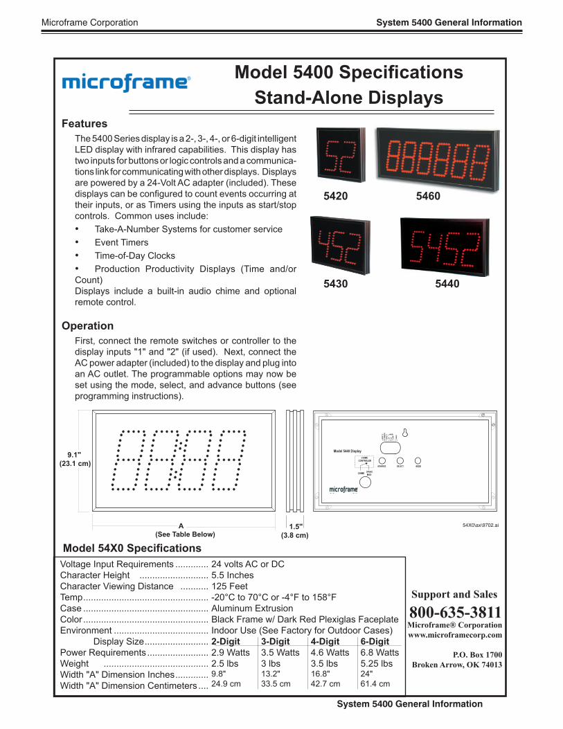
Model 5400 Specifi cations
Stand-Alone Displays
Voltage Input Requirements .............
Character Height ...........................
Character Viewing Distance ...........
Temp .................................................
Case .................................................
Color .................................................
Environment .....................................
Display Size .........................
Power Requirements ........................
Weight .........................................
Width "A" Dimension Inches .............
Width "A" Dimension Centimeters ....
24 volts AC or DC
5.5 Inches
125 Feet
-20°C to 70°C or -4°F to 158°F
Aluminum Extrusion
Black Frame w/ Dark Red Plexiglas Faceplate
Indoor Use (See Factory for Outdoor Cases)
2-Digit 3-Digit 4-Digit 6-Digit
2.9 Watts 3.5 Watts 4.6 Watts 6.8 Watts
2.5 lbs 3 lbs 3.5 lbs 5.25 lbs9.8" 13.2" 16.8" 24"
24.9 cm 33.5 cm 42.7 cm 61.4 cm
Support and Sales
800-635-3811Microframe® Corporation
www.microframecorp.com
P.O. Box 1700
Broken Arrow, OK 74013
Model 54X0 Specifi cations
5420
5430 5440
5460
Features
The 5400 Series display is a 2-, 3-, 4-, or 6-digit intelligent
LED display with infrared capabilities. This display has
two inputs for buttons or logic controls and a communica-
tions link for communicating with other displays. Displays
are powered by a 24-Volt AC adapter (included). These
displays can be confi gured to count events occurring at
their inputs, or as Timers using the inputs as start/stop
controls. Common uses include:
• Take-A-Number Systems for customer service
• Event Timers
• Time-of-Day Clocks
• Production Productivity Displays (Time and/or
Count)
Displays include a built-in audio chime and optional
remote control.
Operation
First, connect the remote switches or controller to the
display inputs "1" and "2" (if used). Next, connect the
AC power adapter (included) to the display and plug into
an AC outlet. The programmable options may now be
set using the mode, select, and advance buttons (see
programming instructions).
1.5"
(3.8 cm)
9.1"
(23.1 cm)
A
(See Table Below)
54X0\ax\9702.ai
CO
MM
ON
B AINP
UT
2
24V
AC
INP
UT
1 485
CO
M
Model 5440 Display
C O R P O R A T I O N
MICROFRAME
ADVANCE SELECT MODE
CHIME
CONTROLER
24VAC
MAXCHIME
Microframe Corporation System 5400 General Information
System 5400 General Information
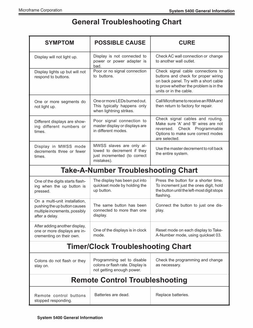
General Troubleshooting Chart
SYMPTOM POSSIBLE CAUSE CURE
Display will not light up.
Display lights up but will not
respond to buttons.
One or more segments do
not light up.
Different displays are show-
ing different numbers or
times.
Display in MWSS mode
decrements three or fewer
times.
One of the digits starts fl ash-
ing when the up button is
pressed.
On a multi-unit installation,
pushing the up button causes
multiple increments, possibly
after a delay.
After adding another display,
one or more displays are in-
crementing on their own.
Colons do not fl ash or they
stay on.
Remote control buttons
stopped responding.
Display is not connected to
power or power adapter is
bad.
Poor or no signal connection
to buttons.
One or more LEDs burned out.
This typically happens only
when lightning strikes.
Poor signal connection to
master display or displays are
in different modes.
MWSS slaves are only al-
lowed to decrement if they
just incremented (to correct
mistakes).
The display has been put into
quickset mode by holding the
up button.
The same button has been
connected to more than one
display.
One of the displays is in clock
mode.
Programming set to disable
colons or fl ash rate. Display is
not getting enough power.
Batteries are dead.
Check AC wall connection or change
to another wall outlet.
Check signal cable connections to
buttons and check for proper wiring
on back panel. Try with a short cable
to prove whether the problem is in the
units or in the cable.
Call Microframe to receive an RMA and
then return to factory for repair.
Check signal cables and routing.
Make sure 'A' and 'B' wires are not
reversed. Check Programmable
Options to make sure correct modes
are selected.
Use the master decrement to roll back
the entire system.
Press the button for a shorter time.
To increment just the ones digit, hold
the button until the left-most digit stops
fl ashing.
Connect the button to just one dis-
play.
Reset mode on each display to Take-
A-Number mode, using quickset 03.
Check the programming and change
as necessary.
Replace batteries.
Take-A-Number Troubleshooting Chart
Timer/Clock Troubleshooting Chart
Remote Control Troubleshooting
Microframe Corporation System 5400 General Information
System 5400 General Information
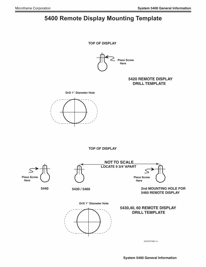
5400 Remote Display Mounting Template
5420 REMOTE DISPLAY DRILL TEMPLATE
Place Screw Here
Drill 1" Diameter Hole
TOP OF DISPLAY
5430,40, 60 REMOTE DISPLAY DRILL TEMPLATE
Drill 1" Diameter Hole
TOP OF DISPLAY
Place Screw Here
NOT TO SCALE LOCATE 9 3/4"APART
Place Screw Here
2nd MOUNTING HOLE FOR
5460 REMOTE DISPLAY
A5400\PX\9801.ai
5430 / 54605440

Microframe Corporation
604 S. 12th Street
Broken Arrow, OK 74012
Tel: (918) 258-4839
Toll Free: 1-800-635-3811
Website: www.microframecorp.com
E-mail: [email protected]