series 4200 - fagerberg ... 9 ring joint 7 open lever 0 no gag ... 4. remove cap assembly: remove...
TRANSCRIPT

Technical Manual 806T R1
Series 4200Maintenance Manual

1
Table of ContentsIntroduction Numbering System ...........................................................................1
Bill of Materials..........................................................................................2
Disassembly ..............................................................................................3Nozzle & Disc Refacing/Lapping Nozzle Refacing ................................................................................4 Disc Refacing ....................................................................................4 Lapping Procedures ..........................................................................4
Assembly ...................................................................................................4Setting & Testing Initial Ring Setting .............................................................................6 Set Pressure Tolerance ......................................................................6
Valve Setting For Steam Service ........................................................6 Basic Ring Functions .........................................................................7 Method of Securing the Adjusting Rings ............................................7 Ring Adjustments ..............................................................................7 Blowdown Tolerance .........................................................................8 Seat Tightness Test ...........................................................................8 Final Notes ........................................................................................8
Troubleshooting .........................................................................................8
Appendix A: Adjusting Ring Settings ...........................................................9
Appendix B: Critical Nozzle & Disc Dimensions ........................................10
Introduction
42 F A 1 2 – 1 7 0Series Number Orifice/Area Sq. In.
Seat Construction Temp. & Materials Inlet Class1 Inlet Facing Cap Construction Test Gag
42 F 0.316
G 0.518
H 0.809
J 1.325
K 1.897
L 2.938
M 3.822
N 4.471
P 6.573
Q 11.39
A Metal Seat 1 To 800°F
3 801°F to 1000°F
0 1501
2 300
3 600
1 Raised Face
9 Ring Joint
7 Open Lever 0 No Gag
1 Test Gag
Numbering System
The chart below illustrates the Farris Series 4200 valve type numbering system. The type number is imprinted on the nameplate of every Farris Series 4200 valve and describes its construction and metallurgy. Valve types with numbers ending in “SP” are special valves. Example: 42FA12-170/SP. Contact the Farris Factory for assistance when replacement parts or maintenance are required on these valves.
1 Valves with 150# inlet flanges available on application. Consult the factory.

2
Built in conformance to ASME Code Section I & Section VIII. Capacity certified by National Board (steam service).
4200 Series Bill of Materials
Bill of MaterialsItem Part Name Material
1Body (up to 800 °F) SA-216 GR. WCB
Carbon Steel
Body (801 °F to 1000 °F) SA-217 GR.WC6 Alloy St. (1 1/4 CR – 1/2 Moly)
2 Bonnet (Open) SA-216 GR. WCB Carbon Steel
3 Nozzle 316 St. St.
4 Disc Precipitation Hardened St. St.
5Disc Holder (L to Q Orifice Only) (up to 800 °F) Stainless Steel
(801 °F to 1000 °F) Monel
6Guide (Up to 800 °F) Stainless Steel
(801 °F to 1000 °F) Monel
7 Stem Stainless Steel
8 Adjusting Ring-Upper Stainless Steel
9 Adjusting Ring-Lower Stainless Steel
10 Lock Screw (Adj. Ring) (2) Stainless Steel
11 Lock Screw Stud (Adj. Ring) (2) Stainless Steel
12 Jam Nut, Lock Screw (2) Stainless Steel
13 Stem Collar Stainless Steel
14 Lift Stop (L-Q only) Stainless Steel
15 Spring (Up to 1000 °F) Chrome Alloy
16 Spring Buttons Steel, Pltd.
17 Body Stud ASME A193 Gr. B7 Alloy St.
18 Hex Nut, Body ASME A194 Gr. 2H Alloy St.
19 Spring Adjusting Screw Stainless Steel
20 Jam Nut, Spring Adj. Screw Stainless Steel
21 Spring Pin (Not Shown) Steel
22 Cotter Pin Steel, Pltd.
23 Cap Iron
24 Cap Screw Steel
25 Test Lever Iron
26 Test Lever Fork Iron
27 Stem Test Nut Stainless Steel
28 Jam Nut, Stem Stainless Steel
29 Round Head Rivet (Fork) Steel
30 Round Head Rivet (Lever) Steel
31 Wire Seal St. St. Wire / Lead Seal
32 Nameplate (Not Shown) Stainless Steel
33 Pipe Plug, Body Steel
34 Cotter Pin (2) Fork & Lever (Not Shown) Steel, Pltd.
14
6
8
4
3
9
7
22
5
7
11
12
17
19
30
26
27
7
23
25
2
20
18
8
10
10
11
12
11
3
1
33
9
6
15
16
24
29
4
“L” to “Q” Orifice Detail
28
31
12
13

3
DisassemblyVisually inspect the valve when it arrives in the shop and note its condition when removed from service. Carefully dismantle the valve and look for evidence of wear and corrosion at each stage in the disassembly process. Replace any worn parts with genuine Farris components only. Use of non Farris parts could lead to potentially dangerous operating conditions.
1. Place the valve at a comfortable working height. The work surface should be clean and strong enough to handle the weight of the parts plus the forces required during disassembly and assembly.
2. Record the position of the lever to the outlet as some installations may require nonstandard lever positions.
3. Remove wire seals.
4. Remove cap assembly:
Remove two cotter pins and pull rivets out of test lever and test lever fork
Slide out test lever and test lever fork
Remove cap screws and lift off cap
5. Remove stem jam nut and stem test nut from the end of the stem.
6. Measure the distance from the top of the stem to the top of the spring adjusting screw. Use this measurement when reassembling the valve to approximate the original set pressure.
7. Loosen the spring adjusting screw jam nut and unscrew the spring adjusting screw.
8. Remove the body hex nuts then lift the bonnet and upper spring button over the stem. The upper spring button must be removed with the bonnet because the spring pin extends through the bonnet window.
9. Remove the spring and lower spring button.
10. Loosen the upper and lower adjusting ring lock screw assemblies.
11. Use the stem as a handle to lift the stem and attached parts from the body.
F – K: The disc, guide, and upper adjusting ring will come out with the stem.
Slide the disc and stem out the bottom of the guide
Unscrew disc from stem
L – Q: The disc, disc holder, collar with cotter pin, and lift stop will come out with the stem.
Remove lift stop
Remove cotter pin from collar and stem
Unscrew collar and lift over stem
Lift off the disc holder
Unscrew the disc from the stem
Lift out the guide and upper adjusting ring
12. Unscrew the upper adjusting ring from the guide.
13. Unscrew the lower adjusting ring from the nozzle.
14. Unscrew the nozzle from the body. Be careful not to damage the seat.
15. Clean all parts and threaded surfaces thoroughly.

4
Nozzle & Disc Refacing / LappingInspect the nozzle and disc seats. If machining is not required, go to the lapping section.
Nozzle Refacing1. Measure the length from the nozzle seat to the top of the nozzle flange
and compare with the minimum length listed in Appendix B. The measured length minus the minimum length listed in Appendix B is the maximum amount of material that can be removed during refacing and lapping. Replace the nozzle when the length from the seat to the flange becomes less than dimension “L min” listed in Appendix B.
2. Prior to refacing the nozzle seating area, grip the nozzle flange in a universal three-jaw lathe chuck fitted with soft jaws (preferably with removable top jaws). The jaws should be bored during each set-up to fit the nozzle flange outside diameter.
3. True up the nozzle with a dial indicator to within 0.002” full indicator reading.
4. Machine light cuts across the seat until the damaged areas are removed. The seat should be machined to the smoothest possible finish. Rigidity of the cutting tool is critical.
5. Lap seat to a mirror finish.
Disc Refacing1. Measure the depth of the raised seat. Replace the disc if there is less
than 0.005” of raised seating surface.
2. Prior to refacing the disc seating area, grip the disc outside diameter in a universal three-jaw lathe chuck fitted with soft jaws (preferably with removable top jaws). The jaws should be bored during each set-up to fit the disc outside diameter. Avoid excessive chucking force.
3. True up the disc with a dial indicator, ensuring that the disc outside diameter and seat face are true with each other within 0.002” full indicator reading.
4. Machine light cuts across the seat at 90° to the axis until the damaged areas are removed, facing to the smoothest possible finish. Rigidity of the cutting tool is critical.
5. Lap seat to a mirror finish.
Lapping Procedures (Manual)1. Use a cast iron or Pyrex lapping glass which is known to have a
perfectly flat face.
2. Select the appropriate lapping compound. Use a rough compound for heavy scratches and nicks, medium compound for slight defects, and smooth compound for the final lapping to obtain a mirror finish (32 AARH max.).
3. When lapping the disc, operate with a light figure eight motion over the entire block surface. This motion will ensure complete contact between the disc and lapping surface.
4. Lap the disc until all blemishes and score marks have been removed. Do not contaminate the compound with dirt that could scratch the disc. Keep the compound jar covered when not in use. Only use clean applicators to transfer the compound from the jar to the lapping surface.
5. Follow the same procedure for lapping the nozzle seat. The nozzle can be placed on a table and a lapping block placed on the nozzle. Be sure that the lapping block does not tip over the side of the nozzle (which would cause rounding of the edges). Use a light, rapid figure eight stroke, lifting the block from the nozzle occasionally.
6. Carefully clean compound from all parts. Failure to do so may foul the seat surfaces.
7. Clean lapping glass.
Assembly1. Lubricate all threaded and mating surfaces with Bostik Never-Seez®
or equivalent.
2. Thread body studs into body.
3. Thread nozzle into body and tighten.
4. Thread lower adjusting ring onto nozzle.
5. Thread body pipe plug into body.
6. Thread lower adjusting ring stud into lock screw and screw assembly into body. Adjust the lock screw stud so that it engages the adjusting ring notches without jamming the ring when the lock screw assembly is fully tightened into the body. Secure the lock screw and stud with jam nut.
7. Thread stem into disc and make sure that the disc is free floating, that is the stem head has passed far enough into the disc that the stem / disc threads are no longer engaged.
L – Q valves contain a stem collar to keep the disc holder in place. So additional steps are required to complete the stem / disc assembly:
Slide disc holder over stem and onto disc.
Set disc on flat surface (preferably on a clean rag so the seat doesn’t get scratched) and push stem into disc.
Thread stem collar onto stem until it touches the disc holder, then turn the collar 1-2 notches up (counterclockwise).
Insert cotter pin through collar and stem to lock collar in place.
Verify that disc is not locked too tightly in disc holder by rocking disc side to side. If disc cannot move side to side, loosen collar another notch and check disc rock again.
Note: Bostik Never-Seez is a registered trademark of Bostik Inc.

5
8. Screw the upper adjusting ring onto the guide.
9. The reference point for the upper adjusting ring position is the nozzle seat. The upper ring is set even with the nozzle seat during assembly and the ring adjustments during testing are recorded as number of notches above or below the nozzle seat. The method used to set this starting point is described below.
Place the guide into body counterbore and measure from the top of the guide to the nozzle seat. The measurement can be made with a dial caliper or with a gage like the one shown in the Figure 1.
Remove the guide from the body and transfer the guide-to-seat measurement to the upper adjusting ring as shown in Figure 2.
10. Insert guide and stem / disc assembly into body.
F – K: Slide disc / stem combination into bottom of guide and lower whole assembly into body until the disc sits on the nozzle seat.
L – Q: Insert guide into body recess, then slide disc / disc holder / stem assembly into top of guide and lower disc onto nozzle seat.
11. Thread stud into upper adjusting ring lock screw and screw assembly into body.
12. Adjust the lock screw stud so that it engages the adjusting ring notches without jamming the ring when the lock screw assembly is fully tightened into the body. Secure the lock screw and stud with a jam nut.
13. Place lower spring button over stem to rest on stem shoulder.
14 Place spring on lower spring button.
15. The upper spring button contains a pin that prevents rotational motion of the spring adjusting screw from being transferred to the valve seat. This pin extends out the side of the bonnet and must be installed together with the bonnet. Hold bonnet over stem while placing upper spring button through bonnet window. Lower bonnet and spring button over stem and place spring button onto spring. Center the bonnet over the stem and align body studs with the bonnet holes. Lower bonnet onto stem and body studs. Make sure that the spring pin fits into the slot machined near the top of the bonnet.
16. Thread hex nuts onto body studs and tighten.
17. Place spring adjusting screw over stem and screw into bonnet. Thread the spring adjusting screw into the bonnet until the distance between the tops of the spring adjusting screw and stem equals the value recorded before disassembly.
Work Bench
Gage
Gage
Guide
Guide
Body
Upper Adjusting Ring
Nozzle
Vise
Metal Scale or Straight Edge
Figure 2
Figure 1

6
Setting & TestingInitial Ring SettingSee Appendix A for a table of suggested adjusting ring settings. If this table is unavailable, use the following method to position the rings for initial testing. See “Ring Adjustments” if additional adjustments are necessary.
Upper Ring – Set the lower surface of the upper ring level with the nozzle seat. (This was done at assembly.)
Lower Ring – Turn the lower ring up to touch the disc (F – K) or disc holder (L – Q), then turn down three notches for pressures below 70 psig. For pressures above 70 psig, turn down two additional notches per 100 psig.
Set Pressure ToleranceThe valve shall be set to the pressure specified by the purchase order. The set pressure tolerances of the ASME Boiler & Pressure Vessel Code, Section I, paragraph PG-72.2 shall be applied.
Valve Setting For Steam Service1. All valves for steam service shall be set on steam. Mount valve on the
test stand in an upright vertical position as close to the test drum as possible. Test gages shall be calibrated and mounted with a siphon between the gage and pressure force.
2. Turn the spring adjusting screw clockwise to increase the spring force and raise the set pressure. Verify that the stem does not turn with the spring adjusting screw. A rotating stem could cause the disc to rotate on the nozzle and damage the seats. The spring pin in the upper button is usually sufficient to prevent stem rotation, but pliers can be used to hold the stem if additional resistance is necessary to keep it from turning.
3. A gag is recommended when setting the valve opening pressure in order to reduce wear on the seating surfaces. Generally, backing off the gag half a turn after lightly touching the top of the stem is a good staring point with a cold valve. Since the valve internals have more exposure to the high temperature steam than the bonnet, they expand more. This typically causes the clearance between the stem and gag to decrease significantly. So the gag may need to be readjusted after the valve is hot.
4. Slowly raise the test drum pressure and observe the popping point. Turn the spring adjusting screw until the valve opens at the required pressure, then torque the jam nut to 25 ft-lb. Check the popping point once more after locking the jam nut.
NEVER MAKE ADJUSTMENTS WHEN THE PRESSURE UNDER THE VALVE IS NEAR THE POPPING POINT. THE VALVE COULD POP UNEXPECTEDLY AND CAUSE INJURY. THEREFORE, ALWAYS LOWER THE PRESSURE IN THE VALVE AT LEAST 25% BEFORE MAKING ADJUSTMENTS
Set Pressure, psi (MPa) Tolerance, plus or minus from set pressure
<− 70 (0.5) 2 psi (15 kPa)> 70 (0.5) and <− 300 (2.1) 3% of set pressure> 300 (2.1) and <− 1000 (7.0) 10 psi (70 kPa)> 1000 (7.0) 1% of set pressure

7
Basic Ring FunctionsThe lower ring is used to adjust simmer, obtain a clean popping action, and to cushion the closing action. It is not typically used to adjust blowdown, but if set too high it can increase lift and cause long blowdown. If set too low, the valve will have excessive simmer and could flutter or chatter.
Simmer (also called warning pressure) is the audible or visible escape of steam between the nozzle and disc prior to the valve popping.
The upper ring is the blowdown control. It directs steam from the secondary orifice onto the disc (and disc holder for L – Q valves) to exert more or less lifting force. A low position provides more initial lift but longer blowdown. A high position allows the steam to escape faster, which shortens blowdown, but also reduces lift.
To increase simmer: Move lower ring to the left (clockwise) to lower the ring.
To reduce simmer: Move lower ring to the right (counterclockwise) to raise the ring.
To eliminate hang-up: Move lower ring to the left (clockwise) to lower the ring for sharp closing.
To decrease blowdown: Move upper ring to the right (counterclockwise) to raise the ring.
To increase blowdown: Move upper ring to the left (clockwise) to lower the ring.
To increase lift: Move upper ring to the left (clockwise) to lower the ring.
Method Of Securing The Adjusting RingsEach adjusting ring is held in position with a lock screw that engages the notches (like gear teeth) on the outside diameter of the ring. The lock screw threads into the body from the outside. To change the position of the adjusting ring, loosen the lock screw nut and remove the lock screw assembly. Insert a screwdriver through the lock screw hole in the valve body and rotate the nearest notch on the adjusting ring in the desired direction. Move the ring to the left to lower the ring or to the right to raise the ring. NEVER USE YOU FINGERS TO ADJUST THE RING. Record the number of notches the ring was moved from its original position. Reinstall the lock screw assembly, ensuring that it engages a notch without exerting a side load on the ring.
Ring AdjustmentsSection I of the ASME Boiler & Pressure Vessel Code no longer contains maximum blowdown limits for production valves. However, the code does specify maximum blowdown limits during certification testing. Also, minimum blowdown limits are still required for all Section I valves. This section will describe the proper procedure to adjust blowdown.
The initial ring settings should produce a sharp pop with very little simmer. Those ring positions are considered a starting point and the following adjustments are usually necessary to fine-tune the valve performance.
1. Remove gag in order to obtain accurate blowdown. Pop valve and record pressures for simmer, pop, and reseat.
2. The lower ring is usually set first. From the initial position, adjust the ring to the lowest position possible without excessive simmer. Simmer should be a maximum of 1% to 2% of the popping pressure.
3. Tighten the lock screw after every adjustment of the upper and lower rings to prevent the rings from rotating as steam flows through the valve.
4. Adjust the upper ring to obtain proper blowdown. Moving the ring five notches at a time is usually sufficient to change blowdown. Raising the upper ring will shorten blowdown but it will also reduce lift. If lift is reduced too much, the valve will not meet capacity standards. Therefore, raise the upper ring high enough to ensure that the valve consistently meets blowdown requirements, but don’t position it unnecessarily high.
5. Adjust the rings until the valve reseats within tolerance and note the settings. Record lower ring setting as notches down from disc holder (disc for F – K). Record upper ring setting as notches up or down from initial setting. If upper ring stays at the initial setting, record as “even.”
6. Adjustment of the rings will often change the set pressure slightly. Therefore, it’s important to verify that the popping point is still within the set pressure tolerance after the rings have been set. The valve is set when pop and reseat pressures are within tolerance.
Final ring settings of valves of similar size and set pressure may differ due to variations in spring rates, or because of manufacturing tolerances, or temperature effects.

8
Blowdown Tolerance
Seat Tighness TestSection I, PG-73.5.3, of the ASME Boiler & Pressure Vessel Code requires a seat tightness test with no visible signs of leakage from the valve. But Section I doesn’t specify a procedure for the test. So the Farris recom-mended test procedure is described below.
1. After set point and blowdown adjustments have been made, tighten the jam nuts to secure the spring adjusting screw and adjusting rings lock screws.
2. Raise the pressure under the valve and hold for three minutes before checking seat tightness.
For set pressures greater than 50 psig, raise the pressure under the valve to 90% of set (the 90% value is a Farris standard, not an ASME requirement).
For set pressures of 50 psig or less, raise the pressure under the valve to 5 psig less than set.
3. Remove any condensate in the body bowl by blowing out with compressed air or nitrogen because the condensate could boil off and give the appearance of a leak.
4. View across the valve outlet against a dark background. For the valve to be acceptable there must be no observable sign of steam leakage at the outlet for at least one minute.
5. If valve is satisfactory, vent pressure under valve, remove valve, and affix wire seal.
Final NotesOnce the valve has been assembled and tested, verify that all necessary records have been completed before putting the valve back into service. These records will provide some guidance as to when to replace components or retire the valve as well as provide a history of the its service life and operating conditions.
The valve should be properly installed in service or prepared for storage. If the valve will be stored, first cover the inlet and outlet to keep foreign matter out of the valve.
1. Valve won’t pop cleanly. Disc doesn’t seem to lift fully.
Lower ring too low. Reset lower ring according to instructions given in Ring Adjustments.
Capacity of valve is greater than steam generating capacity of test system. Verify that the steam source can produce steam at a rate equal to the relieving capacity of the valve.
2. Short Blowdown
Upper ring too high. Lower upper ring.
3. Long Blowdown.
Upper ring too low. Raise upper ring until blowdown is within tolerance.
Lower ring too high. Re-set lower ring to produce a sharp closing, then adjust upper ring to obtain proper blowdown.
4. Valve Leaks – Won’t Pass Seat Tightness Test
Seat Damaged. Repeated popping of a valve can damage the nozzle and disc. Disassemble valve and inspect seating surfaces. Lap nozzle and disc as necessary.
Disc not seated properly in disc holder (L – Q) and isn’t free to tilt slightly to conform to nozzle surface. Shut down boiler and remove valve from test stand. Disassemble valve and verify that the disc is free to “rock” slightly in the disc holder. If disc can’t move, remove collar and reassemble according to instruction in assembly procedure.
5. Valve Flutters or Chatters
Lower ring set too low. Raise ring to lowest position that produces 1% to 2% simmer.
6. Excessive Simmer
Lower ring set too low. Raise ring to lowest position that produces 1% to 2% simmer.
7. Valve Has Sloppy Closing Action
Lower ring set too high. Lower bottom ring until valve closing action is acceptable. Verify that new lower ring setting doesn’t cause excessive simmer.
8. Valve Performance is Inconsistent
Blowdown ring lock screws not tightened. If rings aren’t secure, they will rotate as the steam flows through the valve. Check ring positions and tighten lock screws.
9. Valve doesn’t have enough capacity / lift
Upper adjusting ring set too high. Lower upper ring.
ASME Section I (per PG-73.4.3):Set Pressure, P psig (kPa) Max. Blowdown Min. Blowdown
P < 67 (500) 4 psi (30) 2 psi (15)
67 (500) −< P −< 250 (1700) 6% 2 psi (15)
250 (1700) < P < 375 (2500) 15 psi (100) 2%
P −> 375 (2500) 4% 2%
Percentages are of set pressure.
Troubleshooting
9
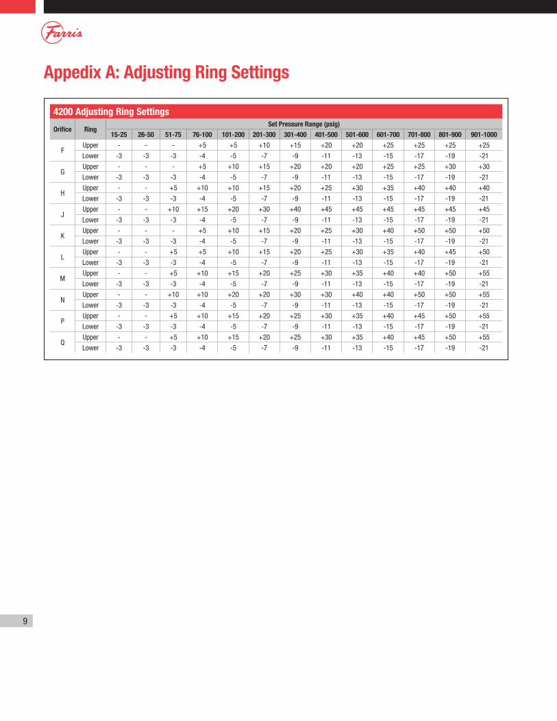
Appedix A: Adjusting Ring Settings
4200 Adjusting Ring Settings
Orifice RingSet Pressure Range (psig)
15-25 26-50 51-75 76-100 101-200 201-300 301-400 401-500 501-600 601-700 701-800 801-900 901-1000
FUpper - - - +5 +5 +10 +15 +20 +20 +25 +25 +25 +25
Lower -3 -3 -3 -4 -5 -7 -9 -11 -13 -15 -17 -19 -21
GUpper - - - +5 +10 +15 +20 +20 +20 +25 +25 +30 +30
Lower -3 -3 -3 -4 -5 -7 -9 -11 -13 -15 -17 -19 -21
HUpper - - +5 +10 +10 +15 +20 +25 +30 +35 +40 +40 +40
Lower -3 -3 -3 -4 -5 -7 -9 -11 -13 -15 -17 -19 -21
JUpper - - +10 +15 +20 +30 +40 +45 +45 +45 +45 +45 +45
Lower -3 -3 -3 -4 -5 -7 -9 -11 -13 -15 -17 -19 -21
KUpper - - - +5 +10 +15 +20 +25 +30 +40 +50 +50 +50
Lower -3 -3 -3 -4 -5 -7 -9 -11 -13 -15 -17 -19 -21
LUpper - - +5 +5 +10 +15 +20 +25 +30 +35 +40 +45 +50
Lower -3 -3 -3 -4 -5 -7 -9 -11 -13 -15 -17 -19 -21
MUpper - - +5 +10 +15 +20 +25 +30 +35 +40 +40 +50 +55
Lower -3 -3 -3 -4 -5 -7 -9 -11 -13 -15 -17 -19 -21
NUpper - - +10 +10 +20 +20 +30 +30 +40 +40 +50 +50 +55
Lower -3 -3 -3 -4 -5 -7 -9 -11 -13 -15 -17 -19 -21
PUpper - - +5 +10 +15 +20 +25 +30 +35 +40 +45 +50 +55
Lower -3 -3 -3 -4 -5 -7 -9 -11 -13 -15 -17 -19 -21
QUpper - - +5 +10 +15 +20 +25 +30 +35 +40 +45 +50 +55
Lower -3 -3 -3 -4 -5 -7 -9 -11 -13 -15 -17 -19 -21

10
Appendix B: Critical Nozzle and Disc DimensionsRefer to this table when machining a nozzle or disc. Replace the part when the minimum dimension is reached.
.005 Min..005 Min..005 Min.
C
B
L(Minimum Length)
A
HH
H
JJJ
D
F
Disc #1 Disc #2 Disc #3
30º
Nozzle Dimensions, Inches Disc Dimensions, Inches
TypeA
+.010 -.000
B +.000 -.005
C +.005 -.005
D +.005 -.005
F +.005 -.005
L Min.
H +.005 -.005
J +.005 -.005
Disc Fig.
42F .634 .750 .870 .032 .050 3.694 .760 .860 1
42G .812 .960 1.080 .032 .050 3.694 .970 1.070 1
42H 1.015 1.200 1.325 .032 .050 3.787 1.210 1.315 2
42J 1.299 1.535 1.685 .032 .050 3.787 1.545 1.675 2
42K 1.554 1.840 2.020 .032 .050 4.315 1.850 2.010 2
42L 1.934 2.290 2.505 .032 .050 5.194 2.300 2.495 3
42M 2.206 2.595 2.835 .032 .050 5.569 2.605 2.825 3
42N 2.386 2.825 3.085 .062 .100 6.725 2.835 3.075 3
42P 2.893 3.425 3.735 .062 .100 6.725 3.435 3.725 3
42Q 3.808 4.475 4.875 .062 .100 9.350 4.485 4.865 3

11/10 3M R1© 2010 Farris Engineering Printed in U.S.A.
10195 Brecksville Road, Brecksville, OH 44141 USA • Telephone: 440-838-7690 • Fax: 440-838-7699 • http://farris.cwfc.comFacilities: Brecksville, Ohio, USA; Brantford, Ontario, Edmonton, Alberta, Canada; Bridport, Dorset, UK; Delhi, India; Tianjin, Beijing, China; Dubai, U.A.E.Offices Worldwide: For a listing of our global sales network, visit our website at http://farris.cwfc.com.
While this information is presented in good faith and believed to be accurate, Farris Engineering, division of Curtiss-Wright Flow Control Corporation, does not guarantee satisfactory results from reliance on such information. Nothing contained herein is to be construed as a warranty or guarantee, expressed or implied, regarding the performance, merchantability, fitness or any other matter with respect to the products, nor as a recommendation to use any product or process in conflict with any patent. Farris Engineering, division of Curtiss-Wright Flow Control Corporation, reserves the right, without notice, to alter or improve the designs or specifications of the products described herein.
Repair valve FAST tags
New valve FAST tags
Farris Aftermarket ServicesFAST Track TurnaroundFarris Engineering is dedicated to making our FAST Program work for you, which is why we have the FAST Track Center at our headquarters in Brecksville, OH. For urgent service requirements, our FAST Track Center has a large inventory of spare parts, finished valves, and dedicated machining and material resources. Farris can provide quick turnaround on inventory and machined parts for both current and obsolete valve designs.
FAST CentersOur FAST Centers are a global network of independently owned and operated valve repair facilities offering:
• Total valve replacement, service and repair any hour, any day: 24/7 – 365
• Local pressure relief valve inventories, plus a Web-accessible global inventory
• Factory trained, ASME and VR certified professionals
• Asset management solutions to keep plants safe
Look for the FAST tag, your assurance
for quality and safety.
In the US or Canada contact 1-877-FARRIS1 or 1-877-327-7747 to find the location of your nearest FAST Center, or for a global listing go to http://farris.cwfc.com/Services/spokes/fast_centers.asp