series 3000a fiberglass pipe and fittings - salvex.com 3000a bondstrand.pdf · series 3000a...
TRANSCRIPT

Series 3000A FiberglassPipe and Fittings
for general oilfield service
FP1065 (10/11)
Uses and applications Brine and brackish water
Frac source and flowback water
Oilfield gathering and transmission lines
Potable water
Source and recycle water
Sump discharge
Water mains
Water treatment
Performance Working pressure to 450 psig depending on pipe size.
No thrust blocks are required at rated system pressure for most buried piping
configurations and most soil conditions. Thrust blocks may be required for 14 and 16-
inch Bondstrand 3000A. For above-ground use, consult Ameron Fiberglass Pipe
Division.
Temperatures to 210°F (99°C) maximum.
Full vacuum capabilities when buried and properly backfilled. For above-ground use,
refer to collapse pressures listed below under pipe pressure performance.
Recommended burial depth: 3 to 25 feet.
Recommended for water, waste water (pH 1 to 12), moderately corrosive liquids and
mild chemicals. Consult Ameron corrosion guide FP132 or Ameron Applications
Engineering for recommendations for your particular application.
Bondstrand Series 3000A is available with the patented Pronto-Lock® and
Pronto-Lock II mechanical joining systems and may be used to temperatures as high
as 210°F (99°C).
Individual system components may not have the same ratings as the pipe.
Refer to the detailed product information for the specific components to
determine the pressure rating for the system as a whole.
Listings MIL-P-29206A for jet fuels and petroleum liquids.
Bondstrand® Product DataFIBERGLASS-COMPOSITE PIPEGROUP
ISO-9001
CERTIFICATED FIRM

Composition Pipe
Filament-wound fiberglass reinforced epoxy pipe with integral epoxy liner and
exterior coating.
NominalPipe Size ASTM Designation
(in) (mm) (D2310) (D2996)
2 - 6 50 - 150 RTRP 11FX RTRP 11FX-5430
8 - 16 200 - 400 RTRP 11FX RTRP 11FX-3210
Fittings
2 to 6-inch
Compression-molded fiberglass reinforced epoxy elbows and tees
Filament-wound and/or mitered crosses, wyes, laterals and reducers
8 to 16-inch
Filament-wound fiberglass reinforced epoxy elbows
Filament-wound and/or mitered crosses, wyes, and laterals
Contact-molded reducers
Flanges
Flange rings:
Molded or filament-wound fiberglass
Stub ends:
Molded or centrifugally cast fiberglass
Blind flanges
Compression-molded fiberglass or epoxy-coated cast iron or steel.
O-rings
Buna-N standard.
Other materials available on request.
Adhesive
Ameron two-part epoxy adhesive for field fabrication.
(consult Ameron for specifications)
Standard 20 and 39-ft random lengths.
Other lengths available on request.
Pipe lengths
Joining systems 2 to 6-inch
Pronto-Lock mechanical coupling.
U.S. Patent No. 3,784,239.
8 to 16-inch
Pronto-Lock II mechanical coupling.
U.S. Patent No. 4,014,568.
2 to 16-inch
Bell and spigot taper/taper adhesive-bonded joint.
2

Ultimate
Nominal Static Ultimate Collapse Pressure2
Pipe Size Pressure Rating Internal Pressure1 80°F 27°C 210°F 99°C
(in) (mm) (psig) (bar) (psig) (bar) (psig) (bar) (psig) (bar)
2 50 450 30 3200 215 145 10.0 125 8.6
3 80 450 30 2400 160 50 3.4 45 3.1
4 100 375 25 2000 135 40 2.8 35 2.4
6 150 300 20 2000 135 35 2.4 30 2.1
8 200 150 10 900 60 25 1.7 21 1.4
10 250 150 10 900 60 18 1.2 12 0.8
12 300 150 10 900 60 12 0.8 9 0.6
14 350 150 10 900 60 10 0.7 7.5 0.5
16 400 150 10 900 60 10 0.7 7.5 0.5
1) Quality control minimum2) For vacuum service above ground in sizes 8 inches and above consult Ameron.
Nominal Pipe Outside Pipe Inside Wall Thickness
Pipe Size Diameter1 Diameter Total Structural
(in) (mm) (in) (mm) (in) (mm) (in) (mm) (in) (mm)
2 50 2.38 60 2.22 56 0.080 1.8 0.073 1.6
3 80 3.50 90 3.31 84 0.086 2.1 0.079 1.8
4 100 4.50 114 4.33 110 0.087 2.2 0.080 1.9
6 150 6.64 168 6.40 162 0.120 3.0 0.113 2.7
8 200 8.63 219 8.30 211 0.150 3.8 0.125 3.2
10 250 10.75 273 10.41 264 0.175 4.4 0.150 3.8
12 300 12.75 324 12.30 312 0.200 5.1 0.175 4.4
14 350 14.44 367 14.01 356 0.215 5.4 0.190 4.8
16 400 16.50 419 16.02 407 0.235 6.0 0.210 5.3
1) Typical outside diameters of 2 through 12-inch pipe are within API, ASTM and ANSI fiberglass and steel pipe dimensions.
Nominal Taper Taper PipePipe Size Angle Length Weight
(in) (mm) (deg) (in) (mm) (lb/ft) (kg/m)
2 50 1.75 1.5 38 0.5 .75
3 80 1.75 1.7 43 0.7 1.05
4 100 1.75 1.9 48 1.0 1.50
6 150 1.75 2.8 71 1.9 2.85
8 200 2.00 2.6 66 3.1 4.60
10 250 2.00 3.1 79 4.5 6.70
12 300 2.00 3.6 91 6.1 9.10
14 350 2.00 4.2 107 7.5 11.15
16 400 2.00 4.7 119 9.4 14.00
3
Typical pipedimensions andweights
Typical pipeperformance
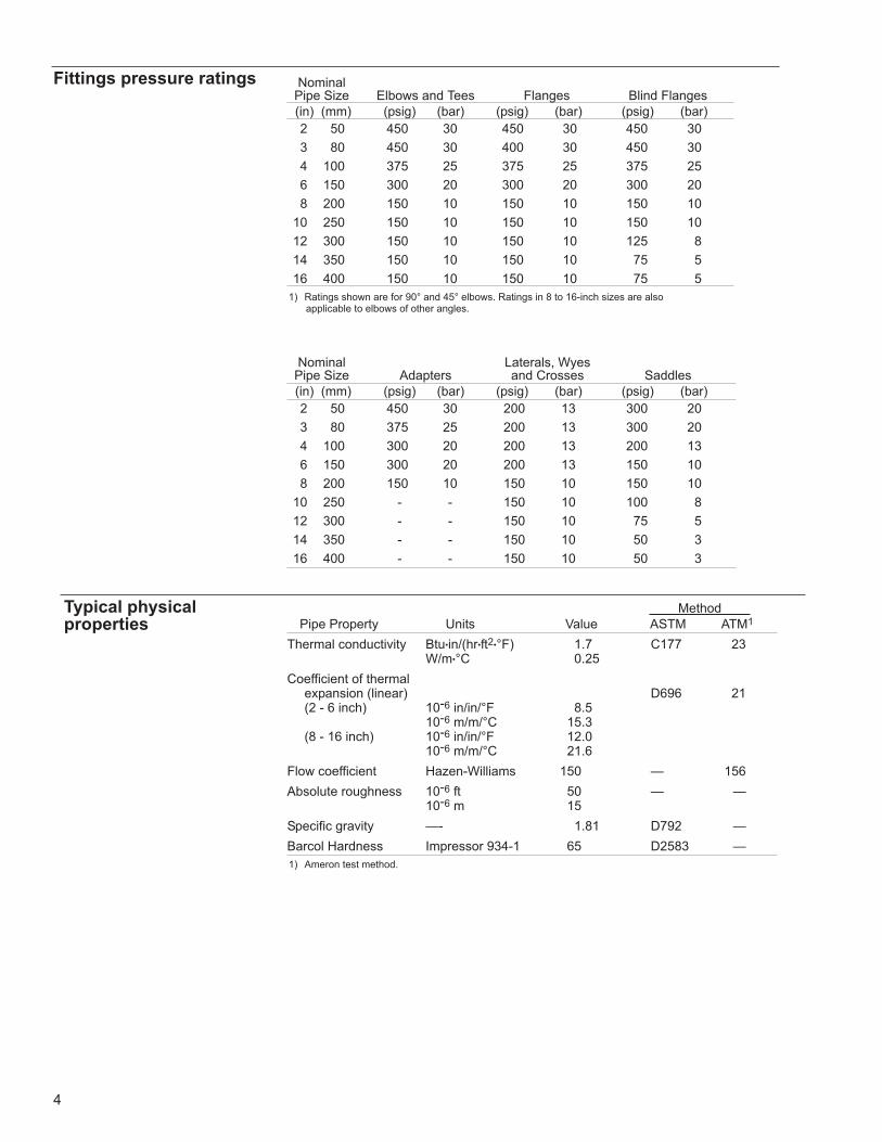
Typical physicalproperties
Method
Pipe Property Units Value ASTM ATM1
Thermal conductivity Btu•in/(hr•ft2•°F) 1.7 C177 23W/m•°C 0.25
Coefficient of thermalexpansion (linear) D696 21(2 - 6 inch) 10-6 in/in/°F 8.5
10-6 m/m/°C 15.3(8 - 16 inch) 10-6 in/in/°F 12.0
10-6 m/m/°C 21.6
Flow coefficient Hazen-Williams 150 — 156
Absolute roughness 10-6 ft 50 — —10-6 m 15
Specific gravity —- 1.81 D792 —
Barcol Hardness Impressor 934-1 65 D2583 —
1) Ameron test method.
4
Nominal Laterals, WyesPipe Size Adapters and Crosses Saddles
(in) (mm) (psig) (bar) (psig) (bar) (psig) (bar)
2 50 450 30 200 13 300 20
3 80 375 25 200 13 300 20
4 100 300 20 200 13 200 13
6 150 300 20 200 13 150 10
8 200 150 10 150 10 150 10
10 250 - - 150 10 100 8
12 300 - - 150 10 75 5
14 350 - - 150 10 50 3
16 400 - - 150 10 50 3
Fittings pressure ratings NominalPipe Size Elbows and Tees Flanges Blind Flanges
(in) (mm) (psig) (bar) (psig) (bar) (psig) (bar)
2 50 450 30 450 30 450 30
3 80 450 30 400 30 450 30
4 100 375 25 375 25 375 25
6 150 300 20 300 20 300 20
8 200 150 10 150 10 150 10
10 250 150 10 150 10 150 10
12 300 150 10 150 10 125 8
14 350 150 10 150 10 75 5
16 400 150 10 150 10 75 5
1) Ratings shown are for 90° and 45° elbows. Ratings in 8 to 16-inch sizes are alsoapplicable to elbows of other angles.
5
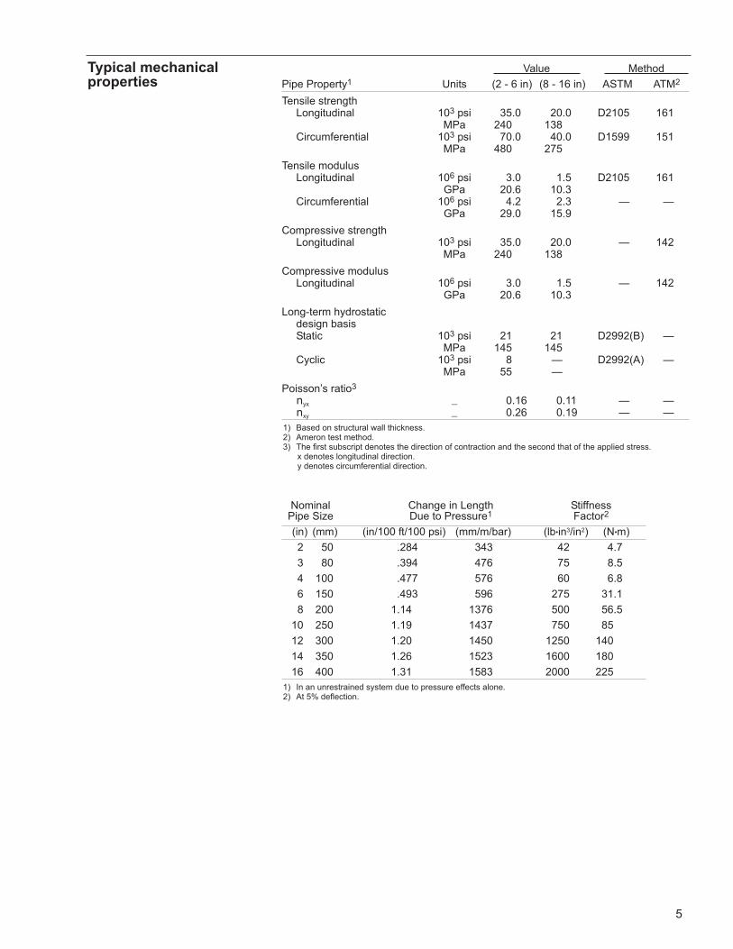
Typical mechanicalproperties
Value Method
Pipe Property1 Units (2 - 6 in) (8 - 16 in) ASTM ATM2
Tensile strengthLongitudinal 103 psi 35.0 20.0 D2105 161
MPa 240 138Circumferential 103 psi 70.0 40.0 D1599 151
MPa 480 275
Tensile modulusLongitudinal 106 psi 3.0 1.5 D2105 161
GPa 20.6 10.3Circumferential 106 psi 4.2 2.3 — —
GPa 29.0 15.9
Compressive strengthLongitudinal 103 psi 35.0 20.0 — 142
MPa 240 138
Compressive modulusLongitudinal 106 psi 3.0 1.5 — 142
GPa 20.6 10.3
Long-term hydrostatic design basisStatic 103 psi 21 21 D2992(B) —
MPa 145 145Cyclic 103 psi 8 — D2992(A) —
MPa 55 —
Poisson’s ratio3
nyx — 0.16 0.11 — —nxy — 0.26 0.19 — —
1) Based on structural wall thickness.2) Ameron test method.3) The first subscript denotes the direction of contraction and the second that of the applied stress.
x denotes longitudinal direction.y denotes circumferential direction.
Nominal Change in Length StiffnessPipe Size Due to Pressure1 Factor2
(in) (mm) (in/100 ft/100 psi) (mm/m/bar) (lb•in3/in2) (N•m)
2 50 .284 343 42 4.7
3 80 .394 476 75 8.5
4 100 .477 576 60 6.8
6 150 .493 596 275 31.1
8 200 1.14 1376 500 56.5
10 250 1.19 1437 750 85
12 300 1.20 1450 1250 140
14 350 1.26 1523 1600 180
16 400 1.31 1583 2000 225
1) In an unrestrained system due to pressure effects alone.2) At 5% deflection.

6
Support spacing Values are based on a 1/2-inch (12 mm) deflection at midspan.
Nominal Single Span1 Continuous Span2
Pipe Size Gases 1.003 1.25 Gases 1.00 1.25
(in) (mm) (ft) (m) (ft) (m) (ft) (m) (ft) (m) (ft) (m) (ft) (m)
2 50 14.4 4.4 9.7 3.0 9.3 2.8 21.5 6.6 14.5 4.4 13.9 4.2
3 80 17.7 5.4 11.1 3.4 10.6 3.2 26.4 8.0 16.6 5.1 15.8 4.8
4 100 20.0 6.1 12.1 3.7 11.5 3.5 29.9 9.1 18.1 5.5 17.2 5.2
6 150 24.9 7.6 14.6 4.5 13.9 4.2 37.2 11.3 21.9 6.7 20.8 6.3
8 200 23.8 7.3 13.9 4.2 13.2 4.0 35.6 10.9 20.8 6.3 19.7 6.0
10 250 26.9 8.2 15.4 4.7 14.6 4.5 40.2 12.3 23.0 7.0 21.9 6.7
12 300 29.3 8.9 16.7 5.1 15.9 4.8 43.8 13.4 25.0 7.6 23.7 7.2
14 350 31.3 9.5 17.6 5.4 16.7 5.1 46.8 14.3 26.3 8.0 25.0 7.6
16 400 33.5 10.2 18.7 5.7 17.8 5.4 50.1 15.3 27.9 8.5 26.6 8.1
1) For fluid temperatures above 78°F (25°C), the span lengths decrease by 0.2 in/°F (9 mm/°C). 2) For intermediate spans. End spans may be calculated by multiplying the single span length by 1.8.3) Fluid specific gravity.
Minimum Maximum MinimumNominal Bending Deflection Length RequiredPipe Size Radius1 per 39-ft Joint for 10° Change
(in) (mm) (ft) (m) (deg) (ft) (m)
2 50 75 23 302 132 4
3 80 100 30 20 20 6
4 100 150 46 15 27 8
6 150 200 61 10 40 12
8 200 300 91 7 + 2 = 93 57 - 13 = 444 12
10 250 350 107 6 + 2 = 8 67 - 13 = 54 16
12 300 400 123 5 + 2 = 7 80 - 13 = 67 20
14 350 450 137 4 + 2 = 6 100 - 13 = 87 27
16 400 500 152 3 + 2 = 5 133 - 13 = 120 37
1) At rated pressure. Sharper bends may create excessive stress concentrations. Do not bend pipe untiladhesive has cured.
2) 2 - 6 inch: pipe only.3) 8 - 16 inch: pipe deflection plus 2° Pronto-Lock II coupling deflection.4) 8 - 16 inch: pipe minimum minus 13-ft (4 m) effect of Pronto-Lock II coupling deflection.
Bending radius

7
Pipe construction Pipe—The structural wall of fiberglass pipe in 2 through 16-inch nominal pipe sizes shall
be constructed of continuous glass fibers wound in a matrix of aromatic amine cured
epoxy resin in a dual angle pattern that takes optimum advantage of the tensile
strength of the filaments. Pipe produced by filament-winding shall have a smooth
outer surface with an outside diametral tolerance not exceeding ±1.0%. The pipe
shall incorporate an integral liner with a nominal thickness of 0.010 ± 0.005 inches for
2 through 6-inch nominal sizes and 0.020 ± 0.005 inches for 8 through 16-inch
nominal sizes. The pipe shall be manufactured in accordance with ASTM Standard
D2996 for filament-wound reinforced thermosetting resin pipe (RTRP). When
classified under ASTM Standard D2310, the pipe shall be Type 1, Grade 1, and Class
F for 2 through 16-inch nominal pipe sizes.
Pipe shall be provided in standard lengths up to 40 feet, and shall be available in 60-ft
lengths on special request to minimize the number of field joints for rapid installation.
Pressure rating—Pipe in 2 through 16-inch sizes shall be rated for a minimum
internal pressure of 150 psig at 210°F. In 2 through 10-inch sizes the pipe shall have
a full vacuum capability at 80°F when installed above ground.
Physical andmechanicalrequirements
Values for physical and mechanical properties shall be no less than 95% of those
shown tabulated above under TYPICAL PHYSICAL PROPERTIES and TYPICAL MECHANICAL
PROPERTIES.
Fittings construction Fittings in 8 through 16-inch nominal sizes shall be filament wound and incorporate a
resin-rich liner of equal or greater thickness than the pipe liner and shall be
constructed of the same glass and resin type for corrosion and abrasion resistance
equal to that of the pipe. Fittings in 2 through 6-inch nominal sizes may be
compression molded from glass and resins similar to those used in the pipe. Contact-
molded, sprayed-up or hand laid-up fittings shall not be permitted.
Pipe and fittings shall be joined using bell and spigot taper/taper adhesive-bonded
joints or mechanical screw-on type joints with O-ring seals inside the bell for rapid
installation.
Workmanship The pipe and fittings shall be free from all defects, including delaminations,
indentations, pinholes, foreign inclusions, bubbles and resin-starved areas which, due
to their nature, degree or extent, detrimentally affect the strength and serviceability of
the pipe or fittings. Pigments or dyes may be used in the resin as long as the product
is sufficiently translucent to verify the structural integrity of the structural wall. The
pipe and fittings shall be as uniform as commercially practicable in color, density and
other physical properties.
Testing Quality control testing—Samples of pipe and fittings shall be tested at random
based on standard quality control practices to determine conformance of the
materials to the following ASTM guidelines for testing fiberglass pipe products: ASTM
D1599, D2105, D2925, D2992A or D2992B. Test samples may be hydrostatically
tested by the manufacturer to 1.5 times the pressure rating for signs of leakage.
Marking Each component shall be marked to show the following
Manufacturer’s name and address
Nominal pipe size
Hydrostatic test pressure (if so ordered)
Date and shift of manufacture (pipe only)
Bondstrand® Guide Specification
© 2011 Ameron • FP1065 (10/11) • Printed in U.S.A.
1 psi = 6895 Pa = 0.07031 kg/cm2
1 bar = 105 Pa = 14.5 psi = 1.02 kg/cm2
1 MPa = 106 Pa = 145 psi = 10.2 kg/cm2
1 GPa = 109 Pa = 145,000 psi = 10,200 kg/cm2
1 in = 25.4 mm
1 ft = 0.3048 m
1 lb•in = 0.113 N•m
1 in4 = 4.162 x 10⁻⁷m4
°C = 5/9 (°F - 32)
Conversions
Important Notice This literature and the information and recommendations it contains are based on data reasonably believed to bereliable. However, such factors as variations in environment, application or installation, changes in operatingprocedures, or extrapolation of data may cause different results. Ameron makes no representation or warranty,express or implied, including warranties of merchantability or fitness for purpose, as to the accuracy, adequacy orcompleteness of the recommendations or information contained herein. Ameron assumes no liability whatsoeverin connection with this literature or the information or recommendations it contains. Product specifications aresubject to change.
Group HeadquartersAmeron International Corporation
Fiberglass-Composite Pipe Division
9720 Cypresswood Drive, Suite 325
Houston, Texas 77070 U.S.A.
Phone: + 1 832 912 8282
Fax: +1 832 912 9393
North AmericaAmeron International Corporation
1004 Ameron Road
P.O. Box 878
Burkburnett, Texas 76354
U.S.A.
Phone: +1 940 569 1471
Fax: +1 940 569 2764
Centron International
600 FM 1195 South
Mineral Wells, Texas 76068
U.S.A.
Phone: +1 940 325 1341
Fax: +1 940 325 9681
Email: [email protected]
EuropeAmeron B.V.
Fiberglass-Composite Pipe
P.O. Box 6
4190 CA Geldermalsen
The Netherlands
Phone: +31 345 587 587
Fax: +31 345 587 561
Email: [email protected]
Asia & Middle EastAmeron (Pte) Ltd.
No. 7A, Tuas Avenue 3
Jurong
Singapore 639407
Phone: +65 6861 6118
Fax: +65 6862 1302/6861 7834
Email: [email protected]
South AmericaAmeron Brasil
Industria e Comercio de Tubos Ltda
Rua Aurora Maria da Conceição, 958
Santa Cruz, Betim
Minas Gerais CEP: 32.530-050
Brazil
Phone: +55 31 3326-6900
www.ameron-fpg.com
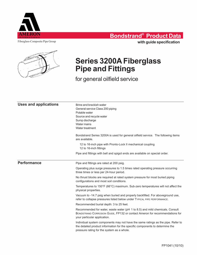
Series 3200A FiberglassPipe and Fittings
for general oilfield service
FP1041 (10/10)
Uses and applications Brine and brackish water
General service Class 200 piping
Potable water
Source and recycle water
Sump discharge
Water mains
Water treatment
Bondstrand Series 3200A is used for general oilfield service. The following items
are available.
12 to 16-inch pipe with Pronto-Lock II mechanical coupling
12 to 16-inch fittings
Pipe and fittings with bell and spigot ends are available on special order.
Performance Pipe and fittings are rated at 200 psig.
Operating plus surge pressures to 1.5 times rated operating pressure occurring
three times or less per 24-hour period.
No thrust blocks are required at rated system pressure for most buried piping
configurations and most soil conditions.
Temperatures to 150°F (66°C) maximum. Sub-zero temperatures will not affect the
physical properties.
Vacuum to -14.7 psig when buried and properly backfilled. For aboveground use,
refer to collapse pressures listed below under TYPICAL PIPE PERFORMANCE.
Recommended burial depth: 3 to 25 feet.
Recommended for water, waste water (pH 1 to 8.5) and mild chemicals. Consult
BONDSTRAND CORROSION GUIDE, FP132 or contact Ameron for recommendations for
your particular application.
Individual system components may not have the same ratings as the pipe. Refer to
the detailed product information for the specific components to determine the
pressure rating for the system as a whole.
Fiberglass-Composite Pipe Group with guide specification
Bondstrand® Product Data

Fittings Elbows:
12 - 16 inch 90° 60° 45° 30° 221⁄2° 111⁄4°
Cast iron pipe end (CIPE) adapters
Tees Flanges Blind flanges
Concentric reducers Sleeve couplings
For fittings dimensions, refer to the most recent release of Ameron product data sheet
FITTINGS 8 THROUGH 16-INCH, FP101.
Composition Pipe
Filament-wound fiberglass reinforced epoxy pipe with integral epoxy liner and
exterior coating.
NominalPipe Size ASTM Designation
(in) (mm) (D2310) (D2996)
12 - 16 200 - 400 RTRP 11FX RTRP 11FX-4420
Fittings
12 to 16-inch:
Filament-wound fiberglass reinforced epoxy elbows
Mitered tees, crosses, wyes, and laterals
Flanges
Molded or filament-wound fiberglass flange rings
Molded or centrifugally cast fiberglass stub ends
Blind flanges
Compression-molded fiberglass or epoxy-coated cast iron or steel
O-rings
Buna-N standard; other materials available on request
Adhesive
PSX•20 two-part epoxy
Joining systems 12 to 16-inch:
Pronto-Lock II mechanical coupling
U.S. Patent No. 4,014,568.
12 to 16-inch:
Bell and spigot taper/taper adhesive-bonded joint
Standard 39-ft random lengths
Other lengths available on request
Pipe lengths
2

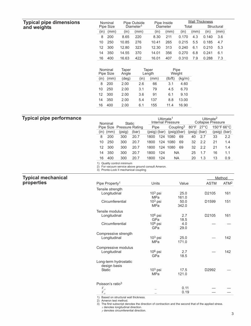
Nominal Pipe Outside Pipe Inside Wall Thickness
Pipe Size Diameter Diameter Total Structural
(in) (mm) (in) (mm) (in) (mm) (in) (mm) (in) (mm)
12 300 12.71 323 12.31 313 0.200 5.1 0.175 4.4
14 350 14.45 367 14.03 356 0.210 5.3 0.185 4.7
16 400 16.52 420 16.06 408 0.230 5.8 0.205 5.2
Typical pipe dimensions
Nominal Taper Taper PipePipe Size Angle Length Weight
(in) (mm) (deg) (in) (mm) (lb/ft) (kg/m)
12 300 2.00 3.6 91 6.1 9.10
14 350 2.00 4.2 107 7.5 11.15
16 400 2.00 4.7 119 9.4 14.00
Ultimate1 Ultimate2
Nominal Static Internal Pressure nn Collapse Pressure
Pipe Size Pressure Rating Pipe Coupling3 80°F 27°C 150°F 66°C
(in) (mm) (psig) (bar) (psig)(bar) (psig)(bar) (psig) (bar) (psig) (bar)
12 300 200 13.6 1200 80 800 55 12 0.8 9 0.6
14 350 200 13.6 1200 80 800 55 10 0.7 7.5 0.5
16 400 200 13.6 1200 80 800 55 10 0.7 7.5 0.5
1) Quality control minimum2) For vacuum service above ground in sizes 12 inches and above consult Ameron.3) Pronto-Lock II mechanical coupling
Typical pipe performance
3
Typical mechanicalproperties
Method
Pipe Property1 Units Value ASTM ATM2
Tensile strengthLongitudinal 103 psi 35.0 D2105 161
MPa 240Circumferential 103 psi 70.0 D1599 151
MPa 480
Tensile modulusLongitudinal 106 psi 3.0 D2105 161
GPa 20.6Circumferential 106 psi 4.2 — —
GPa 29.0
Compressive strengthLongitudinal 103 psi 35.0 — 142
MPa 240
Compressive modulusLongitudinal 106 psi 3.0 — 142
GPa 20.6
Long-term hydrostatic design basisStatic 103 psi 31.5 D2992(B) —
MPa 217Cyclic 103 psi 8 D2992(A) —
MPa 55
Poisson’s ratio3
Vyx — 0.16 — —Vxy — 0.26 — —
1) Based on structural wall thickness.2) Ameron test method.3) The first subscript denotes the direction of contraction and the second that of the applied stress.
x denotes longitudinal direction.y denotes circumferential direction.
When axial movement of the pipe is anticipated, a soft rubber pad should be placed
between the clamp and the pipe. Support clamps should extend at least 120° around
the pipe.
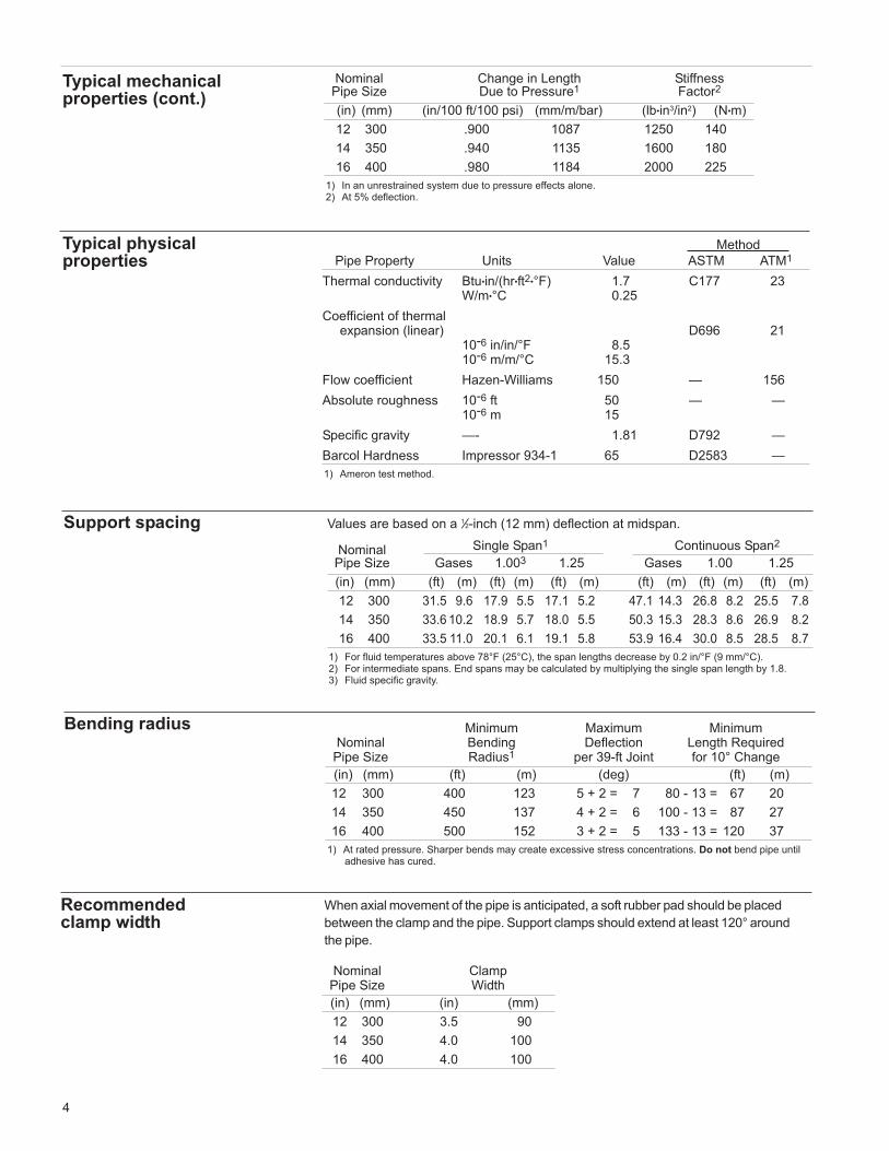
Support spacing Values are based on a 1⁄2-inch (12 mm) deflection at midspan.
Nominal Single Span1 Continuous Span2
Pipe Size Gases 1.003 1.25 Gases 1.00 1.25
(in) (mm) (ft) (m) (ft) (m) (ft) (m) (ft) (m) (ft) (m) (ft) (m)
12 300 31.5 9.6 17.9 5.5 17.1 5.2 47.1 14.3 26.8 8.2 25.5 7.8
14 350 33.6 10.2 18.9 5.7 18.0 5.5 50.3 15.3 28.3 8.6 26.9 8.2
16 400 33.5 11.0 20.1 6.1 19.1 5.8 53.9 16.4 30.0 8.5 28.5 8.7
1) For fluid temperatures above 78°F (25°C), the span lengths decrease by 0.2 in/°F (9 mm/°C). 2) For intermediate spans. End spans may be calculated by multiplying the single span length by 1.8.3) Fluid specific gravity.
Minimum Maximum MinimumNominal Bending Deflection Length RequiredPipe Size Radius1 per 39-ft Joint for 10° Change
(in) (mm) (ft) (m) (deg) (ft) (m)
12 300 400 123 5 + 2 = 7 80 - 13 = 67 20
14 350 450 137 4 + 2 = 6 100 - 13 = 87 27
16 400 500 152 3 + 2 = 5 133 - 13 = 120 37
1) At rated pressure. Sharper bends may create excessive stress concentrations. Do not bend pipe untiladhesive has cured.
Bending radius
Nominal Clamp Pipe Size Width
(in) (mm) (in) (mm)
12 300 3.5 90
14 350 4.0 100
16 400 4.0 100
Recommended clamp width
Typical physicalproperties
Method
Pipe Property Units Value ASTM ATM1
Thermal conductivity Btu•in/(hr•ft2•°F) 1.7 C177 23W/m•°C 0.25
Coefficient of thermalexpansion (linear) D696 21
10-6 in/in/°F 8.510-6 m/m/°C 15.3
Flow coefficient Hazen-Williams 150 — 156
Absolute roughness 10-6 ft 50 — —10-6 m 15
Specific gravity —- 1.81 D792 —
Barcol Hardness Impressor 934-1 65 D2583 —
1) Ameron test method.
Nominal Change in Length StiffnessPipe Size Due to Pressure1 Factor2
(in) (mm) (in/100 ft/100 psi) (mm/m/bar) (lb•in3/in2) (N•m)
12 300 .900 1087 1250 140
14 350 .940 1135 1600 180
16 400 .980 1184 2000 225
1) In an unrestrained system due to pressure effects alone.2) At 5% deflection.
4
Typical mechanicalproperties (cont.)

Guide Specification
Materials Liner—All filament-wound pipe shall incorporate an integral liner with a nominal
thickness of 0.025 ± 0.005 inches for 12 through 16-inch nominal sizes. The resin
system used in the liner shall be a chemically resistant thermosetting epoxy resin
suitable for the intended service.
Structural wall—Pipe shall be filament wound using continuous glass fiber
reinforcements with a resin-compatible finish and a chemically resistant thermo -
setting epoxy resin. The glass filaments shall be wound in a dual-angle pattern that
takes optimum advantage of the tensile strength of the filaments. The glass fiber
content of the reinforced wall shall not be less than 60% by weight. Pigments or
dies may be used in the resin as long as the product remains translucent.
External surface—The pipe shall have a typical 0.005-inch thick resin-rich coating
with organic fibrous reinforcement. This protection must be provided for both above-
and below-ground pipe installations. All external surfaces must be resistant to
anticipated corrosion imposed by the service and the environment.
Fittings—Fittings supplied under this specification shall be filament-wound,
compression molded, centrifugally cast, or manufactured from mitered pipe
sections. The glass fiber content of the structural portion of compression-molded
and filament-wound fittings shall not be less than 55% by weight.
Joining methods Adhesive-bonded bell and spigot—Both tapered bell and tapered spigot shall
have matching taper angles and shall be joined by bonding with an epoxy adhesive.
The nominal taper angle shall be 2° on 12 through 16-inch nominal pipe sizes. The
adhesive shall be a two-part epoxy supplied as a kit with all necessary application
materials.
Mechanical coupling—Nonmetallic threaded mechanical couplings shall have an
O-ring compression seal. The joints shall be capable of carrying the axial load
imposed by the operating pressure. Couplings in 12 through 16-inch nominal pipe
sizes shall be capable of a 2° angular deflection without loss of pressure integrity.
Flanges—Flanges shall be two-piece van Stone type provided with raised grooves
on the sealing surface. Fiberglass-reinforced compression-molded or centrifugally-
cast stub ends are to be adhesive bonded to the pipe or fitting.
Adapters or crossovers—The following adapters or crossovers shall be available
on request:
Cast iron pipe end (12 through 16-inch nominal pipe sizes)
Guide specification This specification covers approval, performance, materials and physical properties
requirements for general oilfield service piping in 12 though 16-inch nominal pipe
sizes at operating temperatures to 200°F.
Listing requirements Pipe, fittings and other components furnished under this specification and intended
for use as below-grade fire protection piping shall be listed with Underwriters
Laboratories for Class 200 service.
Performance requirements Pipe, fittings and other components furnished under this specification shall be rated
for service to 200 psig at 200°F. All components shall be rated at or above the
design pressure of the system.
When classified in accordance with ASTM standards, the pipe shall meet the
following cell limits:
NominalPipe Size ASTM Designation
(in) (mm) (D2310) (D2996)
12 - 16 200 - 400 RTRP 11FX RTRP 11FX-4420
5
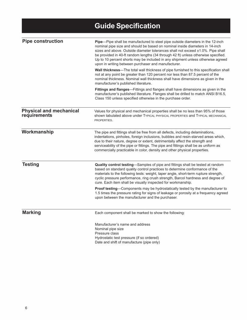
Guide Specification
Pipe construction Pipe—Pipe shall be manufactured to steel pipe outside diameters in the 12-inch
nominal pipe size and should be based on nominal inside diameters in 14-inch
sizes and above. Outside diameter tolerances shall not exceed ±1.0%. Pipe shall
be provided in 40-ft random lengths (34 through 42 ft) unless otherwise specified.
Up to 10 percent shorts may be included in any shipment unless otherwise agreed
upon in writing between purchaser and manufacturer.
Wall thickness—The total wall thickness of pipe furnished to this specification shall
not at any point be greater than 120 percent nor less than 87.5 percent of the
nominal thickness. Nominal wall thickness shall have dimensions as given in the
manufacturer’s published literature.
Fittings and flanges—Fittings and flanges shall have dimensions as given in the
manufacturer’s published literature. Flanges shall be drilled to match ANSI B16.5,
Class 150 unless specified otherwise in the purchase order.
Physical and mechanicalrequirements
Values for physical and mechanical properties shall be no less than 95% of those
shown tabulated above under TYPICAL PHYSICAL PROPERTIES and TYPICAL MECHANICAL
PROPERTIES.
Testing Quality control testing—Samples of pipe and fittings shall be tested at random
based on standard quality control practices to determine conformance of the
materials to the following tests: weight, taper angle, short-term rupture strength,
cyclic pressure performance, ring crush strength, Barcol hardness and degree of
cure. Each item shall be visually inspected for workmanship.
Proof testing—Components may be hydrostatically tested by the manufacturer to
1.5 times the pressure rating for signs of leakage or porosity at a frequency agreed
upon between the manufacturer and the purchaser.
Workmanship The pipe and fittings shall be free from all defects, including delaminations,
indentations, pinholes, foreign inclusions, bubbles and resin-starved areas which,
due to their nature, degree or extent, detrimentally affect the strength and
serviceability of the pipe or fittings. The pipe and fittings shall be as uniform as
commercially practicable in color, density and other physical properties.
Marking Each component shall be marked to show the following:
Manufacturer’s name and address
Nominal pipe size
Pressure class
Hydrostatic test pressure (if so ordered)
Date and shift of manufacture (pipe only)
6
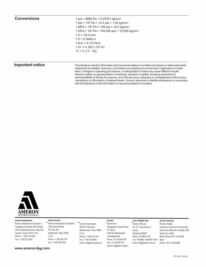
FP1041 (10/10)
This literature and the information and recommendations it contains are based on data reasonablybelieved to be reliable. However, such factors as variations in environment, application or instal-lation, changes in operating procedures, or extrapolation of data may cause different results.Ameron makes no representation or warranty, express or implied, including warranties ofmerchantability or fitness for purpose, as to the accuracy, adequacy or completeness of the recom-mendations or information contained herein. Ameron assumes no liability whatsoever in connectionwith this literature or the information or recommendations it contains.
Important notice
1 psi = 6895 Pa = 0.07031 kg/cm2
1 bar = 105 Pa = 14.5 psi = 1.02 kg/cm2
1 MPa = 106 Pa = 145 psi = 10.2 kg/cm2
1 GPa = 109 Pa = 145,000 psi = 10,200 kg/cm2
1 in = 25.4 mm
1 ft = 0.3048 m
1 lb•in = 0.113 N•m
1 in4 = 4.162 x 10⁻⁷m4
°C = 5/9 (°F - 32)
Conversions
Group HeadquartersAmeron International Corporation
Fiberglass-Composite Pipe Division
9720 Cypresswood Drive, Suite 325
Houston, Texas 77070 U.S.A.
Phone: + 1 832 912 8282
Fax: +1 832 912 9393
North AmericaAmeron International Corporation
1004 Ameron Road
P.O. Box 878
Burkburnett, Texas 76354
U.S.A.
Phone: +1 940 569 1471
Fax: +1 940 569 2764
Centron International
600 FM 1195 South
Mineral Wells, Texas 76068
U.S.A.
Phone: +1 940 325 1341
Fax: +1 940 325 9681
Email: [email protected]
EuropeAmeron B.V.
Fiberglass-Composite Pipe
P.O. Box 6
4190 CA Geldermalsen
The Netherlands
Phone: +31 345 587 587
Fax: +31 345 587 561
Email: [email protected]
Asia & Middle EastAmeron (Pte) Ltd.
No. 7A, Tuas Avenue 3
Jurong
Singapore 639407
Phone: +65 6861 6118
Fax: +65 6862 1302/6861 7834
Email: [email protected]
South AmericaAmeron Brasil
Industria e Comercio de Tubos Ltda
Rua Aurora Maria da Conceição, 958
Santa Cruz, Betim
Minas Gerais CEP: 32.530-050
Brazil
Phone: +55 31 3326-6900
www.ameron-fpg.com

-

Recommended for water, waste water (pH 1 to 8.5) and mild chemicals. Consult
BONDSTRAND CORROSION GUIDE, FP132 or contact Ameron for recommendations for
your particular application.
Individual system components may not have the same ratings as the pipe. Refer to
the detailed product information for the specific components to determine the
pressure rating for the system as a whole.
Bondstrand® Series 3300AFiberglass Pipe and Fittings
for general oilfield service
FP1066 (10/11)
Uses and applications
Performance Pipe and fittings are rated at 300 psig.
Operating plus surge pressures to 1.5 times rated operating pressure occurring
three times or less per 24-hour period.
No thrust blocks are required at rated system pressure for most buried piping
configurations and most soil conditions. For aboveground use, consult Ameron.
Temperatures to 210°F (98°C) maximum. Sub-zero temperatures will not affect the
physical properties.
Vacuum to -14.7 psig when buried and properly backfilled. For aboveground use,
refer to collapse pressures listed below under TYPICAL PIPE PERFORMANCE.
Recommended burial depth: 3 to 25 feet.
Bondstrand® Product Datawith guide specificationFiberglass-Composite Pipe Group
Brine and brackish water
Frac source and flowback water
Oilfield gathering and transmission lines
Potable water
Source and recycle water
Sump discharge
Water mains
ISO-9001
CERTIFICATED FIRM

Composition Pipe
Filament-wound fiberglass reinforced epoxy pipe with integral epoxy liner and
exterior coating.
NominalPipe Size ASTM Designation
(in) (mm) (D2310) (D2996)
8 - 16 200 - 400 RTRP 11FW RTRP 11FW-4320
Fittings
8 to 16 -inch:
Filament-wound fiberglass reinforced epoxy elbows
Mitered tees, crosses, wyes, and laterals
Flanges
Filament-wound fiberglass flange rings
Filament wound fiberglass stub ends
Blind flanges
Epoxy-coated cast iron or steel
O-rings
Buna-N standard; other materials available on request
Adhesive
PSX•20 or PSX•34 two-part epoxy
Joining systems 8 to 12 inch:
Pronto-Lock II mechanical coupling
U.S. Patent No. 4,014,568
8 to 16-inch:
Bell and spigot taper/taper adhesive-bonded joint
Standard 39-ft random lengths
Other lengths available on request
Pipe lengths
2
Elbows:
8 - 16 inch 90° 60° 45° 30° 221/2° 111/4°
Tees Flanges Blind flanges
Concentric reducers Reducer bushings Sleeve couplings
For fittings dimensions, refer to the most recent release of Ameron product data sheets
FITTINGS 8 THROUGH 16-INCH, FP101.
Fittings
Typical mechanicalproperties
Method
Pipe Property1 Units Value ASTM ATM2
Tensile strengthLongitudinal 103 psi 25.0 D2105 161
MPa 161.0Circumferential 103 psi 50.0 D1599 151
MPa 342.0
Tensile modulusLongitudinal 106 psi 2.7 D2105 161
GPa 18.5Circumferential 106 psi 4.0 — —
GPa 29.0
Compressive strengthLongitudinal 103 psi 25.0 — 142
MPa 171.0
Compressive modulusLongitudinal 106 psi 2.7 — 142
GPa 18.5
Long-term hydrostatic design basisStatic 103 psi 17.5 D2992 —
MPa 121.0
Poisson’s ratio3
Vyx — 0.11 — —Vxy — 0.19 — —
1) Based on structural wall thickness.2) Ameron test method.3) The first subscript denotes the direction of contraction and the second that of the applied stress.
x denotes longitudinal direction.y denotes circumferential direction.
Ultimate1 Ultimate2
Nominal Static Internal Pressure nn Collapse Pressure
Pipe Size Pressure Rating Pipe Coupling3 80°F 27°C 150°F 66°C
(in) (mm) (psig) (bar) (psig) (bar) (psig)(bar) (psig) (bar) (psig) (bar)
8 200 300 20.7 1800 124 1080 69 40 2.7 33 2.2
10 250 300 20.7 1800 124 1080 69 32 2.2 21 1.4
12 300 300 20.7 1800 124 1080 69 32 2.2 21 1.4
14 350 300 20.7 1800 124 NA 25 1.7 16 1.1
16 400 300 20.7 1800 124 NA 20 1.3 13 0.9
1) Quality control minimum2) For vacuum service above ground consult Ameron.3) Pronto-Lock II mechanical coupling
Typical pipe performance
3
Nominal Taper Taper PipePipe Size Angle Length Weight
(in) (mm) (deg) (in) (mm) (lb/ft) (kg/m)
8 200 2.00 2.6 66 3.1 4.60
10 250 2.00 3.1 79 4.5 6.70
12 300 2.00 3.6 91 6.1 9.10
14 350 2.00 5.4 137 8.8 13.00
16 400 2.00 6.1 155 11.4 16.90
Nominal Pipe Outside Pipe Inside Wall Thickness
Pipe Size Diameter1 Diameter Total Structural
(in) (mm) (in) (mm) (in) (mm) (in) (mm) (in) (mm)
8 200 8.65 220 8.30 211 0.170 4.3 0.140 3.6
10 250 10.85 276 10.41 265 0.215 5.5 0.185 4.7
12 300 12.80 323 12.30 313 0.240 6.1 0.210 5.3
14 350 14.55 370 14.01 356 0.270 6.8 0.241 6.1
16 400 16.63 422 16.01 407 0.310 7.9 0.288 7.3
Typical pipe dimensionsand weights

Typical physicalproperties
Method
Pipe Property Units Value ASTM ATM1
Thermal conductivity Btu•in/(hr•ft2•°F) 1.7 C177 23W/m•°C 0.25
Coefficient of thermalexpansion (linear) D696 21
10-6 in/in/°F 8.510-6 m/m/°C 15.3
Flow coefficient Hazen-Williams 150 — 156
Absolute roughness 10-6 ft 50 — —10-6 m 15
Specific gravity —- 1.81 D792 —
1) Ameron test method.
4
Support spacing Values are based on a 1/2-inch (12 mm) deflection at midspan.
Nominal Single Span1 Continuous Span2
Pipe Size Gases 1.003 1.25 Gases 1.00 1.25
(in) (mm) (ft) (m) (ft) (m) (ft) (m) (ft) (m) (ft) (m) (ft) (m)
8 200 25.6 7.8 14.9 4.5 14.2 4.3 38.3 11.7 22.3 6.8 21.2 6.4
10 250 28.9 8.8 16.5 5.0 15.7 4.8 43.2 13.1 24.7 7.5 23.5 7.2
12 300 31.5 9.6 17.9 5.5 17.1 5.2 47.1 14.3 26.8 8.2 25.5 7.8
14 350 33.1 10.1 18.8 5.7 17.8 5.4 49.3 15.0 28.0 8.5 26.7 8.1
16 400 36.1 11.0 20.4 6.2 19.5 5.9 53.6 16.3 30.5 9.5 29.0 8.8
1) For fluid temperatures above 78°F (25°C), the span lengths decrease by 0.2 in/°F (9 mm/°C).
2) For intermediate spans. End spans may be calculated by multiplying the single span length by 1.8.
3) Fluid specific gravity.
Minimum Maximum MinimumNominal Bending Deflection Length RequiredPipe Size Radius1 per 39-ft Joint for 10° Change
(in) (mm) (ft) (m) (deg) (ft) (m)
8 200 300 91 7 + 2 = 92 57 - 13 = 443 12.0
10 250 350 107 6 + 2 = 8 67 - 13 = 54 16.0
12 300 400 123 5 + 2 = 7 80 - 13 = 67 20.0
14 350 450 137 4.8 98 81 24.7
16 400 500 152 4.5 130 87 26.5
1) At rated pressure. Sharper bends may create excessive stress concentrations. Do not bend pipe until
adhesive has cured.
2) 8 - 12 inch: pipe deflection plus 2° Pronto-Lock II coupling deflection.
3) 8 - 12 inch: pipe minimum minus 13-ft (4 m) effect of Pronto-Lock II coupling deflection.
Bending radius

Guide Specification
Materials Liner—All filament-wound pipe shall incorporate an integral liner with a nominal
thickness of 0.025 ± 0.005. The resin system used in the liner shall be a chemically
resistant thermosetting epoxy resin suitable for the intended service.
Structural wall—Pipe shall be filament wound using continuous glass fiber
reinforcements with a resin-compatible finish and a chemically resistant thermo -
setting epoxy resin. The glass filaments shall be wound in a dual-angle pattern that
takes optimum advantage of the tensile strength of the filaments. The glass fiber
content of the reinforced wall shall not be less than 60% by weight. Pigments or
dies may be used in the resin as long as the product remains translucent.
External surface—The pipe shall have a typical 0.005-inch thick resin-rich coating
with organic fibrous reinforcement. This protection must be provided for both above-
and below-ground pipe installations. All external surfaces must be resistant to
anticipated corrosion imposed by the service and the environment.
Fittings—Fittings supplied under this specification shall be filament-wound,
compression molded, centrifugally cast, or manufactured from mitered pipe
sections. The glass fiber content of the structural portion of compression-molded
and filament-wound fittings shall not be less than 55% by weight.
Joining methods Adhesive-bonded bell and spigot—Both tapered bell and tapered spigot shall
have matching taper angles and shall be joined by bonding with an epoxy adhesive.
The nominal taper angle shall be 2°. The adhesive shall be a two-part epoxy
supplied as a kit with all necessary application materials.
Mechanical coupling—Nonmetallic threaded mechanical couplings shall have an
O-ring compression seal. The joints shall be capable of carrying the axial load
imposed by the operating pressure. Couplings in 8 through 16-inch nominal pipe
sizes shall be capable of a 2° angular deflection without loss of pressure integrity.
Flanges—Flanges shall be two-piece van Stone type provided with raised grooves
on the sealing surface. Fiberglass-reinforced compression-molded or centrifugally-
cast stub ends are to be adhesive bonded to the pipe or fitting.
Guide specification This specification covers approval, performance, materials and physical properties
requirements for fire protection piping and general industrial service piping in
8 though 16-inch nominal pipe sizes at operating temperatures to 210°F.
Performance requirements Pipe, fittings and other components furnished under this specification shall be rated
for service to 300 psig at 210°F. All components shall be rated at or above the
design pressure of the system.
When classified in accordance with ASTM standards, the pipe shall meet the
following cell limits:
NominalPipe Size ASTM Designation
(in) (mm) (D2310) (D2996)
8 - 16 200 - 400 RTRP 11FW RTRP 11FW-4320
5

Guide Specification
Pipe construction Pipe—Outside diameter tolerances shall not exceed ±1.0%. Pipe shall be provided
in 40-ft random lengths (34 through 42 ft) unless otherwise specified. Up to 10
percent shorts may be included in any shipment unless otherwise agreed upon in
writing between purchaser and manufacturer.
Wall thickness—The total wall thickness of pipe furnished to this specification shall
not at any point be greater than 120 percent nor less than 87.5 percent of the
nominal thickness. Nominal wall thickness shall have dimensions as given in the
manufacturer’s published literature.
Fittings and flanges—Fittings and flanges shall have dimensions as given in the
manufacturer’s published literature. Flanges shall be drilled to match ANSI B16.5,
Class 150 unless specified otherwise in the purchase order.
Physical and mechanicalrequirements
Values for physical and mechanical properties shall be no less than 95% of those
shown tabulated above under TYPICAL PHYSICAL PROPERTIES and TYPICAL MECHANICAL
PROPERTIES.
Testing Quality control testing—Samples of pipe and fittings shall be tested at random
based on standard quality control practices to determine conformance of the
materials to the following tests: weight, taper angle, short-term rupture strength,
cyclic pressure performance, ring crush strength, Barcol hardness and degree of
cure. Each item shall be visually inspected for workmanship.
Components may be hydrostatically tested by the manufacturer to 1.5 times the
pressure rating for signs of leakage or porosity at a frequency agreed upon
between the manufacturer and the purchaser.
Workmanship The pipe and fittings shall be free from all defects, including delaminations,
indentations, pinholes, foreign inclusions, bubbles and resin-starved areas which,
due to their nature, degree or extent, detrimentally affect the strength and
serviceability of the pipe or fittings. The pipe and fittings shall be as uniform as
commercially practicable in color, density and other physical properties.
Marking Manufacturer’s name and address
Nominal pipe size
Pressure class
Hydrostatic test pressure (if so ordered)
Date and shift of manufacture (pipe only)
6
1 psi = 6895 Pa = 0.07031 kg/cm2
1 bar = 105 Pa = 14.5 psi = 1.02 kg/cm2
1 MPa = 106 Pa = 145 psi = 10.2 kg/cm2
1 GPa = 109 Pa = 145,000 psi = 10,200 kg/cm2
1 in = 25.4 mm
1 ft = 0.3048 m
1 lb•in = 0.113 N•m
1 in4 = 4.162 x 10⁻⁷m4
°C = 5/9 (°F - 32)
Conversions

© 2004 Ameron • FP1066 (10/11)
This literature and the information and recommendations it contains are based on data
reasonably believed to be reliable. However, such factors as variations in environment,
application or installation, changes in operating procedures, or extrapolation of data may
cause different results. Ameron makes no representation or warranty, express or
implied, including warranties of merchantability or fitness for purpose, as to the accuracy,
adequacy or completeness of the recommendations or information contained herein.
Ameron assumes no liability whatsoever in connection with this literature or the
information or recommendations it contains.
Important notice
Group HeadquartersAmeron International Corporation
Fiberglass-Composite Pipe Division
9720 Cypresswood Drive, Suite 325
Houston, Texas 77070 U.S.A.
Phone: + 1 832 912 8282
Fax: +1 832 912 9393
North AmericaAmeron International Corporation
1004 Ameron Road
P.O. Box 878
Burkburnett, Texas 76354
U.S.A.
Phone: +1 940 569 1471
Fax: +1 940 569 2764
Centron International
600 FM 1195 South
Mineral Wells, Texas 76068
U.S.A.
Phone: +1 940 325 1341
Fax: +1 940 325 9681
Email: [email protected]
EuropeAmeron B.V.
Fiberglass-Composite Pipe
P.O. Box 6
4190 CA Geldermalsen
The Netherlands
Phone: +31 345 587 587
Fax: +31 345 587 561
Email: [email protected]
Asia & Middle EastAmeron (Pte) Ltd.
No. 7A, Tuas Avenue 3
Jurong
Singapore 639407
Phone: +65 6861 6118
Fax: +65 6862 1302/6861 7834
Email: [email protected]
South AmericaAmeron Brasil
Industria e Comercio de Tubos Ltda
Rua Aurora Maria da Conceição, 958
Santa Cruz, Betim
Minas Gerais CEP: 32.530-050
Brazil
Phone: +55 31 3326-6900
www.ameron-fpg.com

Series 3400 FiberglassEpoxy Pipe Systemsusing Key-Lock® mechanical joint orTaper/Taper adhesive joint
Uses and applications •• Saltwater and seawater lines• Brackish water lines• Fire protection systems (Factory Mutual approved)• Potable water lines• Waste water and sewage systems• Drainage systems• Oil field reinjection systems• Crude oil transmission lines• Temporary pipelines• Electrical conduit• General industrial service for mildly corrosive liquids
Performance Laminate meets requirements of API Specification 15LR.Pipe wall design using a 148 N/mm2 hydrostatic design basis (Procedure B.) with a 0.5service factor. Liner thickness: 0.5 mm.Maximum operating temperature : 93ºC.ASTM-D-2310 Classification: RTRP-11FX.This system is designed to provide minimal 4:1 safety factor in accordance with ASTM-D-1599.
Description PipeFilament-wound fiberglass reinforced epoxy pipe with Key-Lock® male and female mechanical joint orTaper/Taper male and female adhesive joint.
FittingsStandard filament-wound couplings, 45º and 90º Elbows, Tees and Reducing Tees, ConcentricReducers, Flanges* and Nipples. Special fittings are available on request.
* Flanges are available with the following drillings : ANSI B16.5 Class 150 and 300, DIN, ISO & JIS.Other drilling patterns are available on request.
For dimensional data and standard configurations for fittings, please refer to respective Fitting Guides.
© Ameron 1990 FP452 C 01/95 Printed in Holland

Joining systems Key-Lock® integral filament-wound male and female mechanical joint assembled with locking keys.Hydrostatic seal by means of an elastomeric O-ring. Taper/Taper integral filament-wound male andfemale adhesive bonded joint.
Pipe sizes From 50 - 150 mm. (2-6") : 6.1 m. random length.From 200-600 mm. (8-24") : 6.1 or 12.2 m. random lengths.From 700-1000 mm. (28-40"): 11.8 m. random length.
Physical properties Pipe property Units Value MethodThermal conductivity W(m•K) .33 AmeronThermal expansivity 10-6 mm/mm/ºC 18.0 Ameron(lineair)Flow coefficient Hazen-Williams 150 -Absolute roughness 10-6 m 5.3 -Density g/cm3 1.8 -
Mechanical properties Pipe property Units 21ºC 93ºC MethodBi-axialUltimate hoop stress at weeping N/mm2 300 - ASTM D-1599CircumferentialHoop tensile strength N/mm2 300 - ASTM D-2290Hoop tensile modulus N/mm2 25300 22000 ASTM D-2290Poisson's ratio axial/hoop - 0.50 0.65 AmeronLongitudinalAxial tensile strength N/mm2 65 50 ASTM D-2105Axial tensile modulus N/mm2 10000 7800 ASTM D-2105Poisson's ratio hoop/axial - 0.40 0.45 ASTM D-2105Axial bending strength N/mm2 80 - AmeronBeamApparent elastic modulus N/mm2 9200 7000 ASTM D-2925Hydrostatic Design BasisStatic N/mm2 148* - ASTM D-2992
(Proc. B.)Cyclic N/mm2 50* - ASTM D-2992
(Proc. A.)* at 65ºC
Typical pipe dimensions Nominal Pipe lD Minimum total wall thickness* (mm.)pipe size(mm.) (in) (mm.) 3410 3412 3414 3416 3420 3425 3432 3440 3450
50 2 53.2 2.3 2.3 2.3 2.3 2.3 2.3 2.3 2.5 2.880 3 81.8 2.3 2.3 2.3 2.3 2.3 2.4 2.6 3.2 3.9
100 4 105.2 2.3 2.3 2.3 2.5 2.5 2.9 3.2 4.0 5.0150 6 159.0 2.5 2.7 2.8 3.0 3.4 3.9 4.6 5.8 7.2200 8 208.8 3.1 3.1 3.3 3.5 4.0 5.0 5.9 7.5 9.3250 10 262.9 3.5 3.5 3.7 4.3 4.8 6.0 7.3 9.3 11.5300 12 313.7 3.9 4.1 4.3 5.0 5.7 7.1 8.6 10.9 13.6350 14 344.4 4.1 4.5 4.9 5.4 6.1 7.9 9.4 12.0400 16 393.7 4.4 4.8 5.3 6.1 7.0 8.9 10.7 13.6450 18 433.8 4.6 5.5 5.8 6.7 7.6 9.7 11.7 14.9500 20 482.1 5.4 6.0 6.5 7.4 8.3 10.7 13.0 16.5600 24 578.6 6.0 7.0 7.5 8.7 10.1 12.8 15.5700 28 700.0 7.0 7.6 9.0 10.5750 30 750.0 7.2 8.1 9.7 11.2800 32 800.0 7.4 8.6 10.3 11.9900 36 900.0 7.9 9.6 11.4 13.3
1000 40 1000.0 8.6 10.6 12.7 14.7* Total wall thickness is including 0.5 mm. liner
Note: Pipe series designation: First two digits indicate product serie. Final two digits indicateinternal pressure class (bar).
2
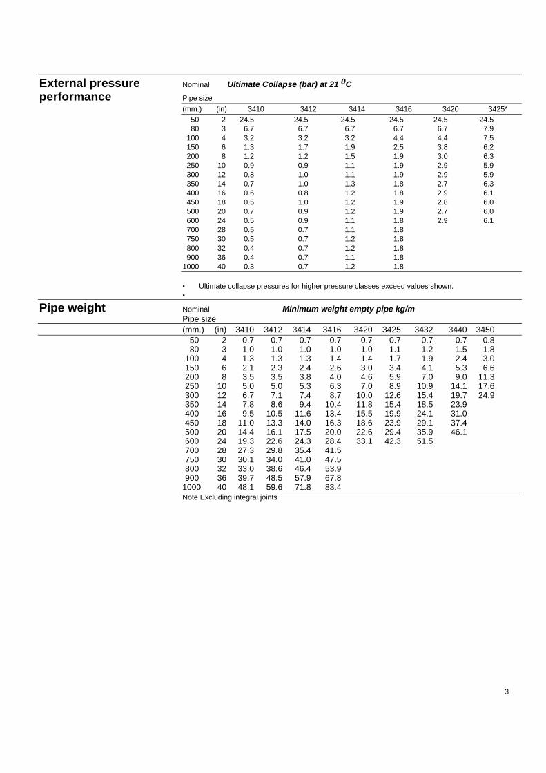
External pressure Nominal Ultimate Collapse (bar) at 21 0C
performance Pipe size
(mm.) (in) 3410 3412 3414 3416 3420 3425*50 2 24.5 24.5 24.5 24.5 24.5 24.580 3 6.7 6.7 6.7 6.7 6.7 7.9
100 4 3.2 3.2 3.2 4.4 4.4 7.5150 6 1.3 1.7 1.9 2.5 3.8 6.2200 8 1.2 1.2 1.5 1.9 3.0 6.3250 10 0.9 0.9 1.1 1.9 2.9 5.9300 12 0.8 1.0 1.1 1.9 2.9 5.9350 14 0.7 1.0 1.3 1.8 2.7 6.3400 16 0.6 0.8 1.2 1.8 2.9 6.1450 18 0.5 1.0 1.2 1.9 2.8 6.0500 20 0.7 0.9 1.2 1.9 2.7 6.0600 24 0.5 0.9 1.1 1.8 2.9 6.1700 28 0.5 0.7 1.1 1.8750 30 0.5 0.7 1.2 1.8800 32 0.4 0.7 1.2 1.8900 36 0.4 0.7 1.1 1.8
1000 40 0.3 0.7 1.2 1.8
• Ultimate collapse pressures for higher pressure classes exceed values shown.•
Pipe weight Nominal Minimum weight empty pipe kg/mPipe size(mm.) (in) 3410 3412 3414 3416 3420 3425 3432 3440 3450
50 2 0.7 0.7 0.7 0.7 0.7 0.7 0.7 0.7 0.880 3 1.0 1.0 1.0 1.0 1.0 1.1 1.2 1.5 1.8
100 4 1.3 1.3 1.3 1.4 1.4 1.7 1.9 2.4 3.0150 6 2.1 2.3 2.4 2.6 3.0 3.4 4.1 5.3 6.6200 8 3.5 3.5 3.8 4.0 4.6 5.9 7.0 9.0 11.3250 10 5.0 5.0 5.3 6.3 7.0 8.9 10.9 14.1 17.6300 12 6.7 7.1 7.4 8.7 10.0 12.6 15.4 19.7 24.9350 14 7.8 8.6 9.4 10.4 11.8 15.4 18.5 23.9400 16 9.5 10.5 11.6 13.4 15.5 19.9 24.1 31.0450 18 11.0 13.3 14.0 16.3 18.6 23.9 29.1 37.4500 20 14.4 16.1 17.5 20.0 22.6 29.4 35.9 46.1600 24 19.3 22.6 24.3 28.4 33.1 42.3 51.5700 28 27.3 29.8 35.4 41.5750 30 30.1 34.0 41.0 47.5800 32 33.0 38.6 46.4 53.9900 36 39.7 48.5 57.9 67.8
1000 40 48.1 59.6 71.8 83.4Note Excluding integral joints
3
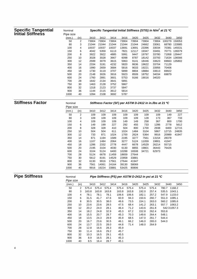
Specific Tangential Nominal Specific Tangential Initial Stiffness (STIS) in N/m2 at 21 ºCInitial Stiffness Pipe size
(mm.) (in) 3410 3412 3414 3416 3420 3425 3432 3440 345050 2 73904 73904 73904 73904 73904 73904 73904 100279 15005380 3 21044 21044 21044 21044 21044 24662 33061 68780 133985
100 4 10037 10037 10037 13691 13691 23396 33034 70381 145531150 6 4042 5359 6113 7821 12117 19347 33491 70771 139379200 8 3922 3922 4885 5991 9447 19797 33780 71958 139447250 10 3028 3028 3667 6098 8787 18142 33793 71634 136566300 12 2599 3079 3615 5963 9141 18446 33623 69663 135802350 14 2334 3191 4232 5820 8636 19622 33704 71129400 16 1990 2659 3684 5816 9033 19221 33956 70406450 18 1730 3119 3707 5899 8804 18884 33613 69922500 20 2148 3026 3916 5923 8509 18752 34034 69879600 24 1760 2891 3601 5753 9166 19016 34020700 28 1642 2134 3641 5891750 30 1463 2128 3752 5867800 32 1318 2123 3737 5847900 36 1144 2115 3612 5814
1000 40 1094 2108 3692 5787
Stiffness Factor Nominal Stiffness Factor (SF) per ASTM D-2412 in in./lbs at 21 ºCPipe size(mm.) (in) 3410 3412 3414 3416 3420 3425 3432 3440 3450
50 2 109 109 109 109 109 109 109 149 22780 3 109 109 109 109 109 128 173 367 733
100 4 109 109 109 149 149 258 367 800 1700150 6 149 199 227 292 455 733 1286 2778 5612200 8 328 328 410 504 800 1700 2938 6400 12715250 10 504 504 611 1024 1484 3104 5867 12715 24835300 12 733 871 1024 1700 2624 5364 9916 20989 41947350 14 871 1194 1589 2195 3277 7561 13154 28378400 16 1107 1484 2064 3277 5124 11059 19801 41947450 18 1286 2332 2778 4447 6678 14529 26214 55715500 20 2195 3104 4030 6130 8855 19801 36443 76426600 24 3104 5124 6400 10288 16508 34721 62973700 28 5124 6678 11459 18659 27644750 30 5612 8191 14529 22858 33881800 32 6130 9916 17561 27644 41947900 36 7561 14061 24164 39130 58069
1000 40 9916 19224 33881 53425 80806
Pipe Stiffness Nominal Pipe Stiffness (PS) per ASTM D-2412 in psi at 21 ºCPipe size(mm.) (in) 3410 3412 3414 3416 3420 3425 3432 3440 3450
50 2 575.4 575.4 575.4 575.4 575.4 575.4 575.4 780.7 1168.280 3 163.8 163.8 163.8 163.8 163.8 192.0 257.4 535.5 1043.1
100 4 78.1 78.1 78.1 106.6 106.6 182.1 257.2 547.9 1133.0150 6 31.5 41.7 47.6 60.9 94.3 150.6 260.7 551.0 1085.1200 8 30.5 30.5 38.0 46.6 73.5 154.1 263.0 560.2 1085.6250 10 23.6 23.6 28.5 47.5 68.4 141.2 263.1 557.7 1063.2300 12 20.2 24.0 28.1 46.4 71.2 143.6 261.8 542:31057.3350 14 18.2 24.8 32.9 45.3 67.2 152.8 262.4 553.8400 16 15.5 20.7 28.7 45.3 70.3 149.6 264.4 548.1450 18 13.5 24.3 28.9 45.9 68.5 147.0 261.7 544.4500 20 16.7 23.6 30.5 46.1 66.2 146.0 265.0 544.0600 24 13.7 22.5 28.0 44.8 71.4 148.0 264.9700 28 12.8 16.6 28.3 45.9750 30 11.4 16.6 29.2 45.7800 32 10.3 16.5 29.1 45.5900 36 8.9 16.5 28.1 45.3
1000 40 8.5 16.4 28.7 45.1
4

Span lengths Nominal Partial span recommendations* (in meters) for horizontal supportPipe size arrangements at21 ºC(mm.) (in) 3410 3412 3414 3416 3420 3425 3432 3440 3450
50 2 3.2 3.2 3.2 3.2 3.2 3.2 3.2 3.2 3.380 3 3.6 3.6 3.6 3.6 3.6 3.6 3.7 3.9 4.1
100 4 3.8 3.8 3.8 3.9 3.9 4.1 4.2 4.4 4.7150 6 4.4 4.4 4.5 4.6 4.7 4.9 5.1 5.4 5.7200 8 5.0 5.0 5.0 5.1 5.3 5.6 5.8 6.2 6.5250 10 5.4 5.4 5.5 5.7 5.9 6.2 6.5 6.9 7.3300 12 5.9 5.9 6.0 6.3 6.5 6.8 7.1 7.6 7.9350 14 6.1 6.2 6.4 6.5 6.7 7.2 7.5 7.9400 16 6.4 6.6 6.7 7.0 7.2 7.7 8.0 8.5450 18 6.7 7.0 7.1 7.3 7.6 8.0 8.4 8.9500 20 7.1 7.3 7.5 7.7 7.9 8.5 8.9 9.4600 24 7.7 8.0 8.1 8.4 8.8 9.3 9.7700 28 8.4 8.6 8.9 9.3750 30 8.6 8.9 9.3 9.6800 32 8.8 9.2 9.6 9.9900 36 9.2 9.7 10.1 10.5
1000 40 9.7 10.2 10.7 11.1
'Note: For continuous span use of above values : plus 20%.For simple span use of above values: minus 20%.
1) Span recommendations are based on pipes tilled with water with a specific gravity of 1000kg/rn3
and include no provision for weights caused by valves, flanges or other heavy objects.2) Span recommendations are calculated for a maximum long time deflection of 13 mm to ensure
good appearance and adequate drainage.
Bending radius Nominal Minimum allowable bending radius(Rb) in m. at 21 ºC andPipe size standard pressure rating(mm.) (in) 3410 3412 3414 3416 3420 3425 3432 3440 3450
50 2 8 8 9 9 11 12 17 21 2780 3 14 15 16 18 23 31 50 46 46
100 4 20 22 26 27 38 42 63 56 53150 6 38 41 48 53 62 74 92 84 83200 8 50 62 72 83 101 94 119 107 108250 10 69 91 113 103 138 129 149 135 139300 12 87 108 136 125 157 151 178 166 166350 14 101 115 131 139 183 156 195 177400 16 126 149 167 159 199 181 220 205450 18 151 147 183 173 225 203 246 227500 20 147 167 194 192 260 227 268 252600 24 199 206 250 235 286 269 322700 28 281 320 299 279750 30 318 344 312 300800 32 358 367 334 321900 36 445 415 387 362
1000 40 520 462 421 404
Note: Do not bend pipe until adhesive has cured. At rated pressure, sharper bends may createexcessive stress concentrations.
Field testing Pipe system is designed for field testing with water at 150% of rated pressure.
Surge pressure Maximum allowable surge pressure is 150% of rated pressure.
5

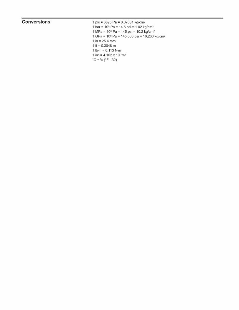
Conversions 1 psi = 6895 Pa = 0.07031 kg/cm2
1 bar = 105Pa = 14.5 psi = 1.02 kg/cm2
1 MPa = 1 N/mm2 = 145 psi = 10.2 kg/cm2
1 inch = 25.4 mm.1 Btu·in/(h•ft2 • ºF) = 0.1442 W/(m•K).ºC = 5/9 (ºF-32).
Important notice This product literature and the recommendations for usage it contains are based on test datareasonably believed to be reliable. It is intended that this literature be used by personnel havingspecialised training in accordance with currently accepted industry practice and normal operatingconditions. Variation in environment, changes in operating procedures, or extrapolation of data maycause unsatisfactory results. We recommend that your engineers verify the suitability of this product foryour intended application. Since we have no control over the conditions of service, we expresslydisclaim responsibility for the results obtained or for any consequential or incidental damages of anykind incurred.
EuropeAmeron B.V.Fiberglass-Composite Pipe P.O. Box 64190 CA GeldermalsenThe NetherlandsPhone: +31 345 587 587Fax: +31 345 587 561E-mail: [email protected]
Group Headquarters Ameron International Corporation - Fiberglass-Composite Pipe Division9720 Cypresswood Drive, Suite 325 - Houston, Texas 77070 - U.S.A.Phone: +1 832 912 8282 - Fax: +1 832 912 9393E-mail: [email protected]
Website: http://www.ameron-fpg.com
AsiaAmeron (Pte) Ltd.No. 7A, Tuas Avenue 3JurongSingapore 639407Phone: +65 6861 6118Fax: +65 6862 1302/6861 7834E-mail: [email protected]
U.S.A.Centron International, Inc.P.O. Box 490600 FM 1195 SouthMineral Wells - Texas 76068U.S.A.Phone: +1 940 325 1341Fax: +1 940 325 9681E-mail: [email protected]
U.S.A.Ameron International Corporation1004 Ameron RoadP.O. Box 878Burkburnett, Texas 76364U.S.A.Phone: +1 940 569 1471Fax: +1 940 569 2764

© Ameron 2005. FP 158 A 08/05. Page 1 of 6. Printed in the Netherlands.
Series 2400 Fiberglass Pipe and Fittingsusing Key-Lock® mechanical joint or Taper/ Taper adhesive joint
Uses and applications ● Saltwater and seawater lines ● Oil field reinjection systems● Brackish water lines ● Crude oil transmission lines● Fire protection systems ● Temporary pipelines● Potable water lines ● Electrical conduit● Waste water and sewage systems ● General industrial service for mildly● Drainage systems corrosive liquids
Performance Laminate meets requirements of API Specification 15LR.Pipe wall design using a 124 N/mm2 hydrostatic design basis (Procedure B.) with a 0.5service factor. Liner thickness: 0.5 mm.Maximum operating temperature: 121°C (250 °F).ASTM D-2310 Classification: RTRP-11FW (or RTRP-11 FE as applicable).This system is designed to provide minimal 4:1 safety factor in accordance with ASTMD-1599.
Description PipeFilament-wound fiberglass reinforced epoxy pipe with Key-Lock‚ male and female orDouble O-Ring male and female mechanical joint or Taper/ Taper male and female adhesivejoint.
FittingsStandard filament-wound couplings, 45° and 90° Elbows, Tees and Reducing Tees,Concentric Reducers, Flanges* and Nipples. Special fittings are available on request.
* Flanges are available with the following drillings : ANSI B16.5 Class 150 and 300, DIN,ISO & JIS. Other drilling patterns are available on request.
For dimensional data and standard configurations for fittings, please refer to the respec-tive Fitting Guides.
Optional, the system can be supplied conductive - Bondstrand 2400C or Fireproofing2400-FP.For conductive ASTM D-2310 Classification: RTRP-11AW for pipes or RTRP-11AE asapplicable.
Key-Lock joint
Taper/Taper joint
C
M
Y
CM
MY
CY
CMY
K
FP158 A-1.pdf 4-8-2005 9:51:37FP158 A-1.pdf 4-8-2005 9:51:37

Joining systems Key-Lock‚ integral filament-wound male and female or Double O-Ring male and femalemechanical joint assembled with locking keys. Hydrostatic seal by means of an elas-tomeric O-ring. Taper/ Taper integral filament-wound male and female adhesive bondedjoint.
Pipe sizes From 50 - 100 mm (2-4”) : 5.85 or 9 m depends on end configuration.For 150 mm (6”) : 5.85, 9 or 11.89 m depends on end configuration.From 200 - 1000 mm (8-40”) : 11.89 m random length.
Physical properties Pipe property Units Value Method
Thermal conductivity W(m•k) .33 AmeronThermal expansivity 10-6 mm/mm/°C 18.0 Ameron (lineair)Flow coefficient Hazen-Williams 150 —Absolute roughness 10-6 m 5.3 —Density g/cm3 1.8 —Shielding capability* volts 1001 —Grounding resistance @1500 volts* 106 ohms 1.01 —
* Applicable for conductive
Mechanical properties Pipe property Units 21°C 93°C Method
Bi-axialUltimate hoop stress at weeping N/mm2 250 — ASTM D-1599CircumferentialHoop tensile strength N/mm2 220 — ASTM D-2290Hoop tensile modulus N/mm2 25200 22100 ASTM D-2290Poisson’s ratio axial/ hoop — 0.65 0.81 AmeronLongitudinalAxial tensile strength N/mm2 80 65 ASTM D-2105Axial tensile modulus N/mm2 12500 9700 ASTM D-2105Poisson’s ratio hoop/ axial — 0.40 0.44 ASTM D-2105Axial bending strength N/mm2 85 — AmeronBeamApparent elastic modulus N/mm2 12500 8000 ASTM D-2925Hydrostatic Design BasisStatic N/mm2 —— 124* ASTM D-2992
(Proc.B.)Cyclic N/mm2 41.5* — ASTM D-2992
(Proc.A.)
* at 65°C
Typical pipe dimensions Nominal Pipe Minimum total wall thickness* (mm)pipe size ID(mm) (in) (mm) 2410 2412 2414 2416 2420 2425 2432 2440 245050 2 53.2 2.3 2.3 2.3 2.3 2.3 2.3 2.3 2.8 3.380 3 81.8 2.3 2.3 2.3 2.3 2.3 2.7 3.1 3.9 4.7100 4 105.2 2.3 2.3 2.3 2.5 2.7 3.3 3.9 4.9 5.9150 6 159.0 2.5 2.7 3.0 3.4 3.8 4.6 5.6 7.0 8.7200 8 208.8 3.1 3.2 3.7 4.2 4.8 5.8 7.2 9.1 11.2250 10 262.9 3.5 3.9 4.5 5.1 5.8 7.2 8.8 11.2 14.0300 12 313.7 3.9 4.5 5.3 6.0 6.8 8.4 10.4 13.4 16.6350 14 344.4 4.1 4.8 5.7 6.6 7.4 9.2 11.4 14.6 18.2400 16 393.7 4.5 5.5 6.4 7.4 8.4 10.5 12.9 15.6450 18 433.8 4.9 6.0 7.0 8.1 9.2 11.5 14.2 18.2500 20 482.1 5.4 6.6 7.7 8.9 10.1 12.7 15.7 20.1600 24 578.6 6.3 7.7 9.3 10.6 12.1 15.1 18.8700 28 700.0 7.4 9.1 10.8 12.6 14.3 17.9 22.3750 30 750.0 7.9 9.7 11.6 13.5 15.3 19.1 23.9800 32 800.0 8.4 10.3 12.3 14.3 16.3 20.4 25.5900 36 900.0 9.3 11.5 13.7 16.0 18.2 22.8 28.51000 40 1000.0 10.3 12.8 15.3 17.8 20.3
* Total wall thickness is including 0.5 mm liner. No liner for conductive pipe
Note: Pipe series designation: First two digits indicate product series. Final two digitsindicate inernal pressure class (bar).
© Ameron 2005. FP 158 A 08/05. Page 2 of 6. Printed in the Netherlands.

© Ameron 2005. FP 158 A 08/05. Page 3 of 6. Printed in the Netherlands.
External pressure Nominal Ultimate Collapse Pressure* (bar)performance pipe size
(mm) (in) 2410 2412 2414 2416 2420 2425*
50 2 26.4 26.4 26.4 26.4 26.4 26.480 3 7.3 7.3 7.3 7.3 7.3 13.2
100 4 3.4 3.4 3.4 4.7 6.2 12.8150 6 1.4 1.8 2.6 4.1 6.1 11.7200 8 1.3 1.5 2.5 3.8 5.9 11.1250 10 1.0 1.5 2.4 3.6 5.6 11.3300 12 0.9 1.4 2.4 3.7 5.5 10.9350 14 0.8 1.3 2.3 3.8 5.5 11.0400 16 0.7 1.4 2.3 3.7 5.5 11.2450 18 0.7 1.4 2.3 3.7 5.5 11.1500 20 0.7 1.4 2.3 3.6 5.4 11.0600 24 0.7 1.3 2.4 3.6 5.5 10.9700 28 0.7 1.3 2.2 3.5 4.9 10.0750 30 0.7 1.3 2.2 3.5 4.9 9.9800 32 0.7 1.3 2.2 3.5 4.9 10.0900 36 0.6 1.2 2.1 3.5 4.9 10.0
1000 40 0.6 1.3 2.2 3.5 4.9 9.9
* Ultimate collapse pressures for higher pressure classes exceed values shown.
Pipe weight Nominal Minimum weight empty pipe kg/mpipe size
(mm) (in) 2410 2412 2414 2416 2420 2425 2432 2440 2450
50 2 0.67 0.67 0.67 0.67 0.67 0.67 0.67 0.84 1.0080 3 1.02 1.02 1.02 1.02 1.02 1.21 1.41 1.81 2.22
100 4 1.30 1.30 1.30 1.42 1.55 1.93 2.31 2.95 3.61150 6 2.13 2.32 2.60 2.97 3.35 4.11 5.06 6.42 8.10200 8 3.52 3.64 4.25 4.86 5.60 6.84 8.60 11.02 13.74250 10 5.02 5.64 6.56 7.48 8.56 10.75 13.27 17.11 21.67300 12 6.71 7.80 9.26 10.55 12.03 15.00 18.76 24.49 30.71350 14 7.75 9.15 10.96 12.78 14.40 18.07 22.61 29.31400 16 9.76 12.04 14.11 16.41 18.73 23.63 29.29 35.74450 18 11.75 14.51 17.04 19.83 22.64 28.55 35.56 46.11500 20 14.43 17.78 20.87 24.26 27.66 35.08 43.74 56.63600 24 20.29 24.98 30.37 34.77 39.87 50.15 62.96700 28 28.94 35.83 42.75 50.11 56.90 61.98 90.30750 30 33.15 40.96 49.25 57.58 65.30 71.93 103.80800 32 37.65 46.44 55.74 65.09 74.30 82.25 118.10900 36 46.97 58.43 69.94 82.03 93.10 93.75 148.10
1000 40 57.90 72.37 86.90 101.51 115.90
Note: Excluding integral joints
© Ameron 2005. FP 158 A 08/05. Page 4 of 6. Printed in the Netherlands.
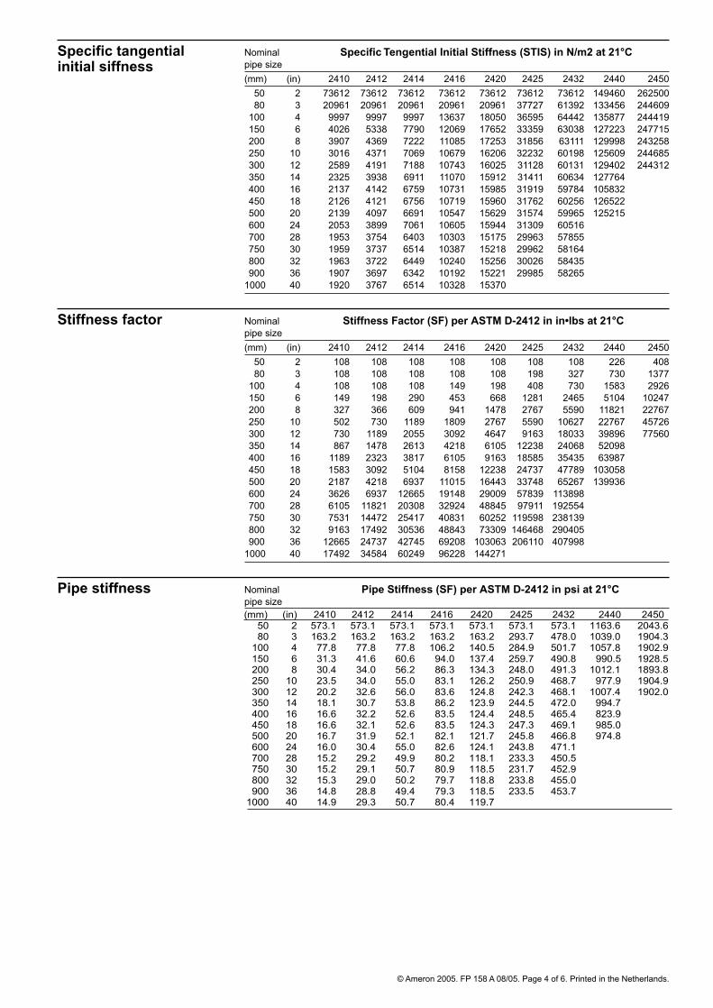
Specific tangential Nominal Specific Tengential Initial Stiffness (STIS) in N/m2 at 21°Cinitial siffness pipe size
(mm) (in) 2410 2412 2414 2416 2420 2425 2432 2440 245050 2 73612 73612 73612 73612 73612 73612 73612 149460 26250080 3 20961 20961 20961 20961 20961 37727 61392 133456 244609
100 4 9997 9997 9997 13637 18050 36595 64442 135877 244419150 6 4026 5338 7790 12069 17652 33359 63038 127223 247715200 8 3907 4369 7222 11085 17253 31856 63111 129998 243258250 10 3016 4371 7069 10679 16206 32232 60198 125609 244685300 12 2589 4191 7188 10743 16025 31128 60131 129402 244312350 14 2325 3938 6911 11070 15912 31411 60634 127764400 16 2137 4142 6759 10731 15985 31919 59784 105832450 18 2126 4121 6756 10719 15960 31762 60256 126522500 20 2139 4097 6691 10547 15629 31574 59965 125215600 24 2053 3899 7061 10605 15944 31309 60516700 28 1953 3754 6403 10303 15175 29963 57855750 30 1959 3737 6514 10387 15218 29962 58164800 32 1963 3722 6449 10240 15256 30026 58435900 36 1907 3697 6342 10192 15221 29985 58265
1000 40 1920 3767 6514 10328 15370
Stiffness factor Nominal Stiffness Factor (SF) per ASTM D-2412 in in•lbs at 21°Cpipe size(mm) (in) 2410 2412 2414 2416 2420 2425 2432 2440 2450
50 2 108 108 108 108 108 108 108 226 40880 3 108 108 108 108 108 198 327 730 1377
100 4 108 108 108 149 198 408 730 1583 2926150 6 149 198 290 453 668 1281 2465 5104 10247200 8 327 366 609 941 1478 2767 5590 11821 22767250 10 502 730 1189 1809 2767 5590 10627 22767 45726300 12 730 1189 2055 3092 4647 9163 18033 39896 77560350 14 867 1478 2613 4218 6105 12238 24068 52098400 16 1189 2323 3817 6105 9163 18585 35435 63987450 18 1583 3092 5104 8158 12238 24737 47789 103058500 20 2187 4218 6937 11015 16443 33748 65267 139936600 24 3626 6937 12665 19148 29009 57839 113898700 28 6105 11821 20308 32924 48845 97911 192554750 30 7531 14472 25417 40831 60252 119598 238139800 32 9163 17492 30536 48843 73309 146468 290405900 36 12665 24737 42745 69208 103063 206110 407998
1000 40 17492 34584 60249 96228 144271
Pipe stiffness Nominal Pipe Stiffness (SF) per ASTM D-2412 in psi at 21°Cpipe size
(mm) (in) 2410 2412 2414 2416 2420 2425 2432 2440 2450 50 2 573.1 573.1 573.1 573.1 573.1 573.1 573.1 1163.6 2043.6
80 3 163.2 163.2 163.2 163.2 163.2 293.7 478.0 1039.0 1904.3 100 4 77.8 77.8 77.8 106.2 140.5 284.9 501.7 1057.8 1902.9 150 6 31.3 41.6 60.6 94.0 137.4 259.7 490.8 990.5 1928.5 200 8 30.4 34.0 56.2 86.3 134.3 248.0 491.3 1012.1 1893.8 250 10 23.5 34.0 55.0 83.1 126.2 250.9 468.7 977.9 1904.9 300 12 20.2 32.6 56.0 83.6 124.8 242.3 468.1 1007.4 1902.0 350 14 18.1 30.7 53.8 86.2 123.9 244.5 472.0 994.7 400 16 16.6 32.2 52.6 83.5 124.4 248.5 465.4 823.9 450 18 16.6 32.1 52.6 83.5 124.3 247.3 469.1 985.0 500 20 16.7 31.9 52.1 82.1 121.7 245.8 466.8 974.8 600 24 16.0 30.4 55.0 82.6 124.1 243.8 471.1 700 28 15.2 29.2 49.9 80.2 118.1 233.3 450.5 750 30 15.2 29.1 50.7 80.9 118.5 231.7 452.9 800 32 15.3 29.0 50.2 79.7 118.8 233.8 455.0 900 36 14.8 28.8 49.4 79.3 118.5 233.5 453.7
1000 40 14.9 29.3 50.7 80.4 119.7
C
M
Y
CM
MY
CY
CMY
K
Acr53.pdf 4-8-2005 9:39:31Acr53.pdf 4-8-2005 9:39:31
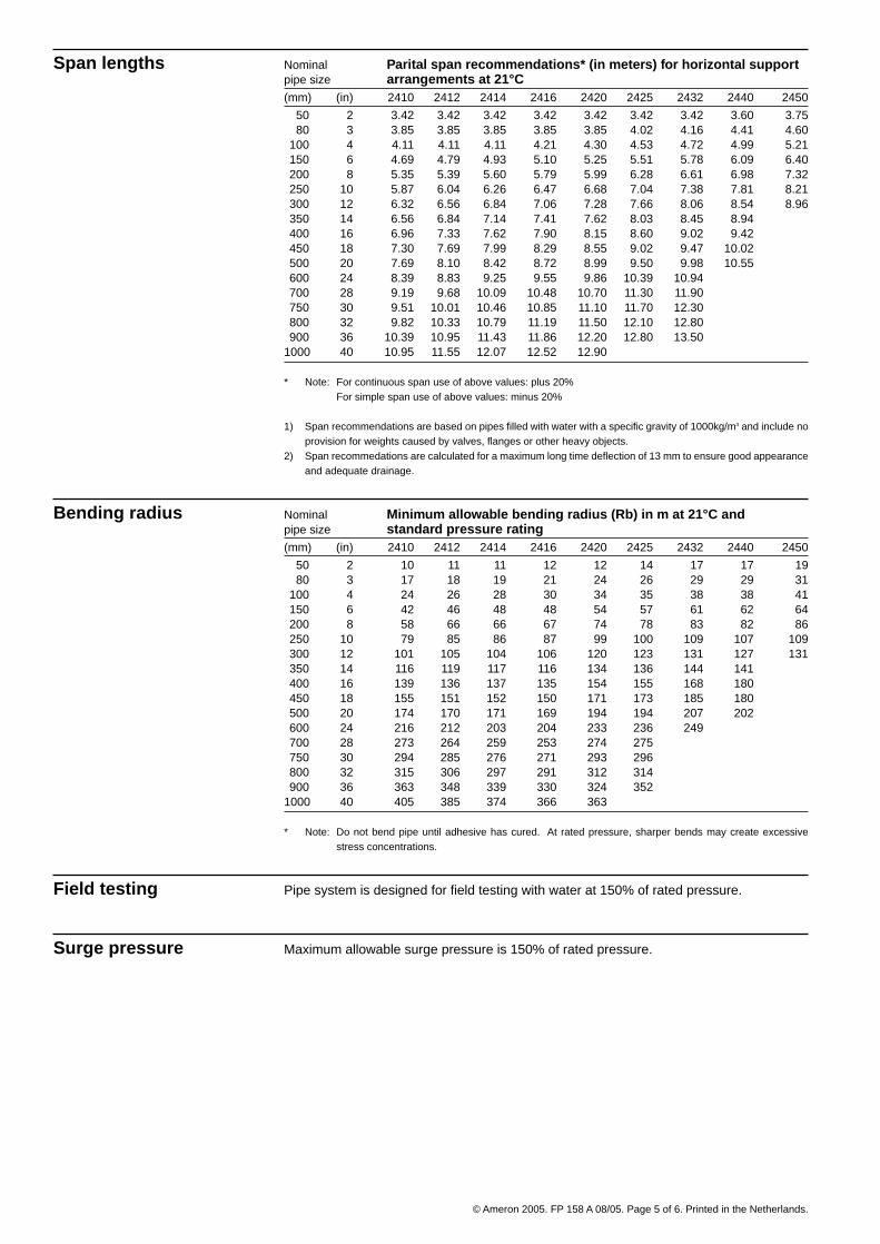
Span lengths Nominal Parital span recommendations* (in meters) for horizontal supportpipe size arrangements at 21°C(mm) (in) 2410 2412 2414 2416 2420 2425 2432 2440 2450
50 2 3.42 3.42 3.42 3.42 3.42 3.42 3.42 3.60 3.7580 3 3.85 3.85 3.85 3.85 3.85 4.02 4.16 4.41 4.60
100 4 4.11 4.11 4.11 4.21 4.30 4.53 4.72 4.99 5.21150 6 4.69 4.79 4.93 5.10 5.25 5.51 5.78 6.09 6.40200 8 5.35 5.39 5.60 5.79 5.99 6.28 6.61 6.98 7.32250 10 5.87 6.04 6.26 6.47 6.68 7.04 7.38 7.81 8.21300 12 6.32 6.56 6.84 7.06 7.28 7.66 8.06 8.54 8.96350 14 6.56 6.84 7.14 7.41 7.62 8.03 8.45 8.94400 16 6.96 7.33 7.62 7.90 8.15 8.60 9.02 9.42450 18 7.30 7.69 7.99 8.29 8.55 9.02 9.47 10.02500 20 7.69 8.10 8.42 8.72 8.99 9.50 9.98 10.55600 24 8.39 8.83 9.25 9.55 9.86 10.39 10.94700 28 9.19 9.68 10.09 10.48 10.70 11.30 11.90750 30 9.51 10.01 10.46 10.85 11.10 11.70 12.30800 32 9.82 10.33 10.79 11.19 11.50 12.10 12.80900 36 10.39 10.95 11.43 11.86 12.20 12.80 13.50
1000 40 10.95 11.55 12.07 12.52 12.90
* Note: For continuous span use of above values: plus 20%For simple span use of above values: minus 20%
1) Span recommendations are based on pipes filled with water with a specific gravity of 1000kg/m3 and include noprovision for weights caused by valves, flanges or other heavy objects.
2) Span recommedations are calculated for a maximum long time deflection of 13 mm to ensure good appearanceand adequate drainage.
Bending radius Nominal Minimum allowable bending radius (Rb) in m at 21°C andpipe size standard pressure rating(mm) (in) 2410 2412 2414 2416 2420 2425 2432 2440 2450
50 2 10 11 11 12 12 14 17 17 1980 3 17 18 19 21 24 26 29 29 31
100 4 24 26 28 30 34 35 38 38 41150 6 42 46 48 48 54 57 61 62 64200 8 58 66 66 67 74 78 83 82 86250 10 79 85 86 87 99 100 109 107 109300 12 101 105 104 106 120 123 131 127 131350 14 116 119 117 116 134 136 144 141400 16 139 136 137 135 154 155 168 180450 18 155 151 152 150 171 173 185 180500 20 174 170 171 169 194 194 207 202600 24 216 212 203 204 233 236 249700 28 273 264 259 253 274 275750 30 294 285 276 271 293 296800 32 315 306 297 291 312 314900 36 363 348 339 330 324 352
1000 40 405 385 374 366 363
* Note: Do not bend pipe until adhesive has cured. At rated pressure, sharper bends may create excessivestress concentrations.
Field testing Pipe system is designed for field testing with water at 150% of rated pressure.
Surge pressure Maximum allowable surge pressure is 150% of rated pressure.
© Ameron 2005. FP 158 A 08/05. Page 5 of 6. Printed in the Netherlands.

Conversions 1 psi = 6895 Pa = 0.07031 kg/cm2
1 bar = 105Pa = 14.5 psi = 1.02 kg/cm2
1 Mpa = 1 N/mm2 = 145 psi = 10.2 kg/cm2
1 inch = 25.4 mm1 Btu.in/(h•ft2•°F) = 0.1442 W/(m•K)° C = 5/9 (°F-32)
Important Notice This literature and the information and recommendations it contains are based on datareasonably believed to be reliable. However, such factors as variations in environment,application or installation, changes in operating procedures, or extrapolation of data maycause different results. Ameron makes no representation or warranty, express or implied,including warranties of merchantability or fitness for purpose, as to the accuracy, ade-quacy or completeness of the recommendations or information contained herein. Ameronassumes no liability whatsoever in connection with this literature or the information orrecommendations it contains.
Fiberglass-CompositePipe GroupEuropeAmeron B.V.P.O. Box 64190 CA GeldermalsenThe NetherlandsPhone: (+31) 345 587 587Fax: (+31) 345 587 561e-mail: [email protected]: http://www.ameron-fpg.nl
Fiberglass-CompositePipe GroupThe AmericasP.O. Box 878Burkburnett, Texas 76364U.S.A.Phone: (+1) 940 569 1471Fax: (+1) 940 569 2764
Fiberglass-CompositePipe Group Headquarters9720 Cypresswood Drive, Suite 325Houston, TX 77070U.S.A.Phone: (+1) 832 912 8282Fax: (+1) 832 912 9393e-mail: [email protected]: http://www.ameron.com
Fiberglass-CompositePipe GroupAsiaAmeron (Pte) LtdNo. 7A, Tuas Avenue 3JurongSingapore 639407Phone: (+65) 6861 6118Fax: (+65) 6862 1302/6861 7834e-mail: [email protected]: http://www.ameron.com.sg
C
M
Y
CM
MY
CY
CMY
K
Acr1EB.pdf 3-8-2005 15:43:11Acr1EB.pdf 3-8-2005 15:43:11