series 300 valves 300 valves edition 04/2018 dorotdorot’’s areas of s areas of 2 dorot, part of...
TRANSCRIPT
Pro
du
ct
Ca
talo
gu
e
Se
rie
s 3
00
Va
lve
s
Series 3
00 V
alv
es
Cata
logue
Editi
on 0
4/20
18
Series 300 Valves
Series 300 Valves
Edition 04/2018
Dorot’s Areas Of Dorot’s Areas Of
2
Dorot, part of Matholding Group since 2014, is one of the world’s leading manufacturers and developers
of sustainable technologies and products for water control and optimization systems.
With more than 70 years of experience, the company is a worldwide pioneer
in providing high quality solutions for Hydraulic Controlled Valves and Air Valves.
Customers around the globe benefit on a daily basis from our experience and wide variety of solutions and services in the following areas:
Waterworks Distribution Systems for civil and industrial engineering Fire Protection Industrial Applications such as Mining,
Wastewater, Marine Water Treatment and Filtration
Agricultural and Landscape Irrigation Water Metering and others
Innovation and expertise are the backbones of Dorot. It drove us into developing a
diverse portfolio of water and other fluids systems application, in compliance with
specifications and international quality standards. Customer satisfaction and recognition is of paramount importance for Dorot. This guarantees uncompromised know-how, expertise and professionalism in planning, designing and providing the optimal hydraulic control solutions.
We invite you to join our family of business partners.Together we can provide the best control solutions for
the world’s most valuable natural resource: water
Series 300 Valves
Edition 04/2018
Contents
General Information 4Overview 4Features 4Engineering Data 5Technical Specifications 5Materials 5Basic Valve Operating Modes 6Typical Pressure Reducing Performance Chart 10Cavitation Data 11Dimensions & Weights 12Size Selection Tables 14Headloss Charts 15Components 16Waterworks Control Application 17Electronic and Remote control functions 17EL Solenoid Control Valve 17EL\TO Two Stage Opening Solenoid Control Valve 18EC Electronic Control Valve 19Pressure Regulating functions 20PR Pressure-Reducing Valve 20PR[D] Proportional Pressure-Reducing Valve 21PRM Dual Set-Point Pressure-Reducing Valve 22HyMod Flow-Modulated Pressure-Reducing Valve 23PS[R] Pressure-Sustaining\Relief Valve 24PS Pressure-Sustaining Valve 25PR\PS Pressure Sustaining\Reducing Valve 26DI Pressure Differential Sustaining Valve 27Rate of Flow Regulating functions 28FR Flow Control Valve 28FR\EL Flow Control Valve 29Water Level Control functions 30FL Modulating Float Valve 30FLEL Electric Float Controlled Valve 31FLDI Differential Float Valve 32FLDI\PS Differential Float and Pressure Sustaining Valve 33FLDI\FR(PR) Differential Float and Flow Control Valve 34FLDI\SP Differential-Level Control Valve with Surge-Preventing closure 35AL 3W Altitude Pilot Controlled Valve 36CXAL 2W Altitude Pilot Controlled Valve 37Pump Control functions 38BC Pump Control Valve 39BC\PS Pump Control and Pressure Sustaining Valve 39NS Two-Stages, Cushioned Closure Check Valve 40CV Hydraulic Non-Return Valve 41DW Deep Well (Borehole) Pump Control Valve 42Safety functions 43RE Surge Anticipating Valve 43REEL Surge Anticipating Valve 44QR Quick Pressure-Relief Valve 45FE Excessive Flow Shut-off Valve 46Fire Protection Applications 47
Series 300 Valves
Edition 04/2018
4
General Information
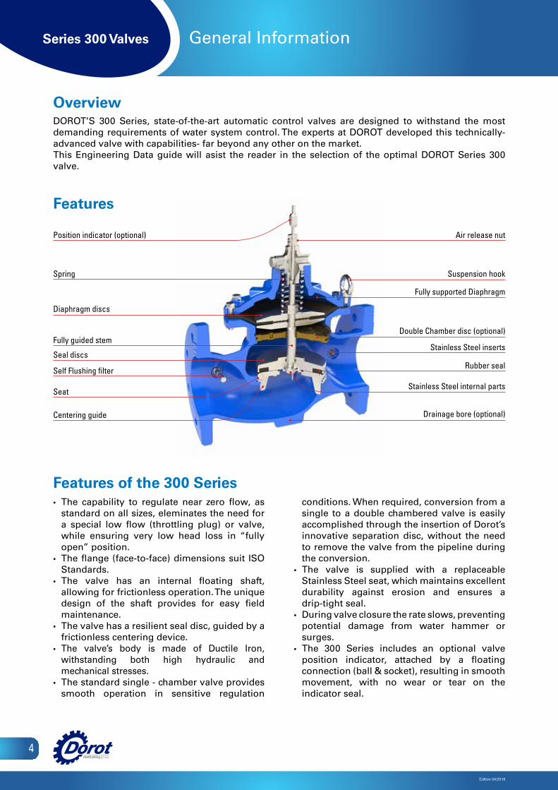
• The capability to regulate near zero flow, as standard on all sizes, eleminates the need for a special low flow (throttling plug) or valve, while ensuring very low head loss in “fully open” position.
• The flange (face-to-face) dimensions suit ISO Standards.
• The valve has an internal floating shaft, allowing for frictionless operation. The unique design of the shaft provides for easy field maintenance.
• The valve has a resilient seal disc, guided by a frictionless centering device.
• The valve’s body is made of Ductile Iron, withstanding both high hydraulic and mechanical stresses.
• The standard single - chamber valve provides smooth operation in sensitive regulation
conditions. When required, conversion from a single to a double chambered valve is easily accomplished through the insertion of Dorot’s innovative separation disc, without the need to remove the valve from the pipeline during the conversion.
• The valve is supplied with a replaceable Stainless Steel seat, which maintains excellent durability against erosion and ensures a drip-tight seal.
• During valve closure the rate slows, preventing potential damage from water hammer or surges.
• The 300 Series includes an optional valve position indicator, attached by a floating connection (ball & socket), resulting in smooth movement, with no wear or tear on the indicator seal.
Features of the 300 Series
Position indicator (optional)
Spring
Stainless Steel inserts
Diaphragm discs
Fully guided stem
Seal discs
Seat
Centering guide
Air release nut
Suspension hook
Fully supported Diaphragm
Double Chamber disc (optional)
Rubber seal
Stainless Steel internal parts
Drainage bore (optional)
Overview DOROT’S 300 Series, state-of-the-art automatic control valves are designed to withstand the most demanding requirements of water system control. The experts at DOROT developed this technically-advanced valve with capabilities- far beyond any other on the market.This Engineering Data guide will asist the reader in the selection of the optimal DOROT Series 300 valve.
Features
Self Flushing filter
Series 300 Valves
Edition 04/2018
5
Engineering Data
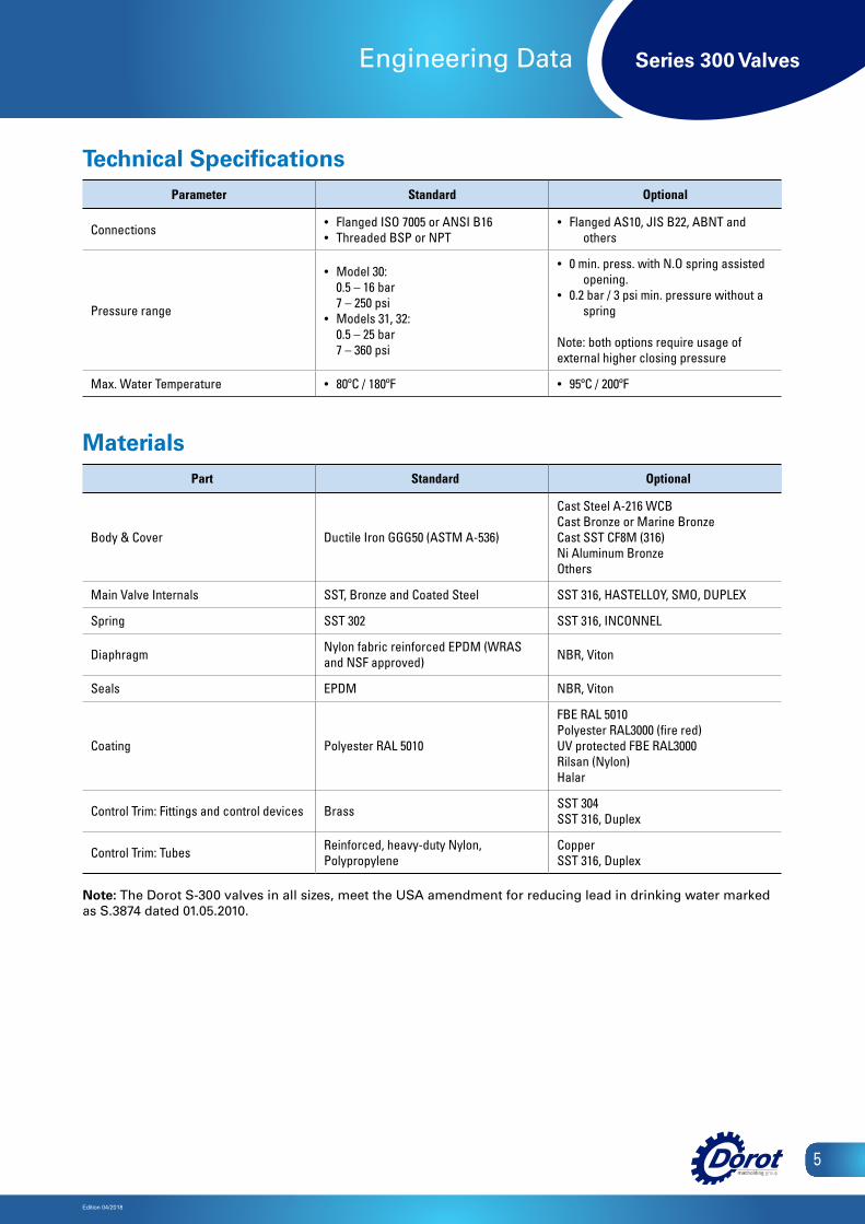
Technical SpecificationsParameter Standard Optional
Connections • Flanged ISO 7005 or ANSI B16• Threaded BSP or NPT
• Flanged AS10, JIS B22, ABNT and others
Pressure range
• Model 30: 0.5 – 16 bar 7 – 250 psi
• Models 31, 32: 0.5 – 25 bar 7 – 360 psi
• 0 min. press. with N.O spring assisted opening.
• 0.2 bar / 3 psi min. pressure without a spring
Note: both options require usage of external higher closing pressure
Max. Water Temperature • 80ºC / 180ºF • 95ºC / 200ºF
MaterialsPart Standard Optional
Body & Cover Ductile Iron GGG50 (ASTM A-536)
Cast Steel A-216 WCBCast Bronze or Marine BronzeCast SST CF8M (316)Ni Aluminum BronzeOthers
Main Valve Internals SST, Bronze and Coated Steel SST 316, HASTELLOY, SMO, DUPLEX
Spring SST 302 SST 316, INCONNEL
Diaphragm Nylon fabric reinforced EPDM (WRAS and NSF approved) NBR, Viton
Seals EPDM NBR, Viton
Coating Polyester RAL 5010
FBE RAL 5010Polyester RAL3000 (fire red)UV protected FBE RAL3000Rilsan (Nylon)Halar
Control Trim: Fittings and control devices Brass SST 304SST 316, Duplex
Control Trim: Tubes Reinforced, heavy-duty Nylon, Polypropylene
CopperSST 316, Duplex
Note: The Dorot S-300 valves in all sizes, meet the USA amendment for reducing lead in drinking water marked as S.3874 dated 01.05.2010.

Series 300 Valves
Edition 04/2018
6
Engineering Data
Standard (Single Chamber) ValveClosed Mode: The control pressure (taken from the pipeline) is applied by the control device to the control chamber (top of the diaphragm). The pipeline pressure pushes the seal to open, and the control chamber pressure forces the diaphragm to close. Since the diaphragm area is larger than the seal area, it has greater hydraulic force so the valve remains in the closed position.
Open Mode: The control device relieves the pressure from the control chamber. The pipeline pressure forces the seal to the “open” position so that the fluid can pass through the valve. While the valve is open, outlet pressure is applied to the lower side of the diaphragm, assisting the opening.
Double Chamber Valve (Version D)The double chamber version is created by inserting a separation disc between the diaphragm and the seal. This assembly creates a second control chamber below the diaphragm, permitting for the activation of the valve in low-pressure systems and enabling the activation faster valve response. The response to varying conditions is quick, since closure downward movement is not resisted by pressure below the diaphragm.
Closed Mode: The control pressure (taken from the pipeline or from supplementary pressure source) is applied to the top of the external diaphragm. The bottom control chamber drains. The pipeline pressure pushes the seal to open, but since the diaphragm area is larger than the seal area it creates greater hydraulic force and which forces the valve to close thus the valve closes. At this stage, the bottom chamber should be drained.
Open Mode: The control device releases the pressure from the top control chamber.The seal assembly is forced to the “open” position by the pipeline pressure, allowing flow through the valve.
Closed Mode
Opened Mode
Closed Mode
Opened Mode
Basic Valve Operating Modes On-Off Mode
Closed Mode
Open Mode
Closed Mode
Open Mode
D chamber - Closed Mode
D chamber - Open Mode
ControlDevice
SeparationDisc
ControlDevice
D chamber - Closed Mode
D chamber - Open Mode
ControlDevice
SeparationDisc
ControlDevice
Series 300 Valves
Edition 04/2018
7
Engineering Data
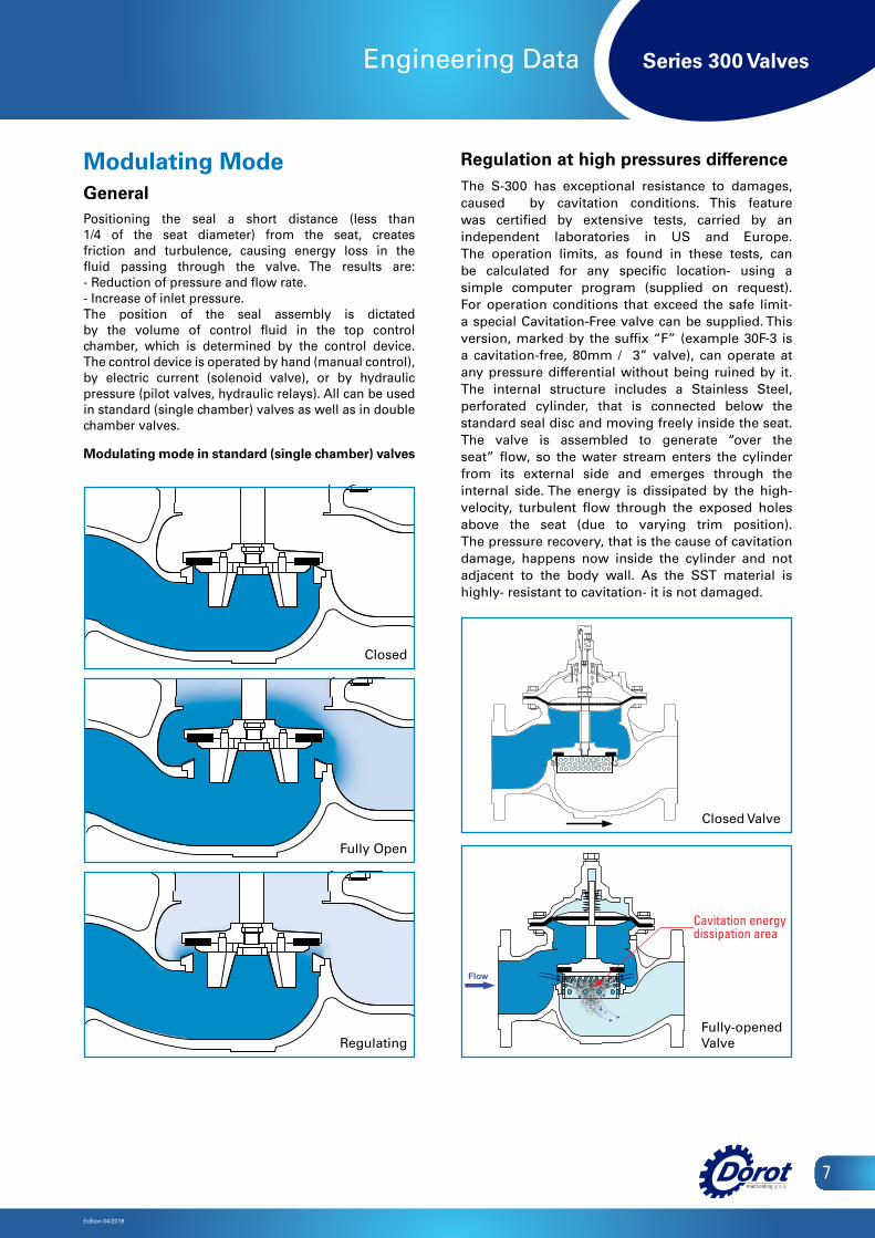
Modulating ModeGeneralPositioning the seal a short distance (less than 1/4 of the seat diameter) from the seat, creates friction and turbulence, causing energy loss in the fluid passing through the valve. The results are: - Reduction of pressure and flow rate.- Increase of inlet pressure.The position of the seal assembly is dictated by the volume of control fluid in the top control chamber, which is determined by the control device. The control device is operated by hand (manual control), by electric current (solenoid valve), or by hydraulic pressure (pilot valves, hydraulic relays). All can be used in standard (single chamber) valves as well as in double chamber valves.
Modulating mode in standard (single chamber) valves
Regulation at high pressures differenceThe S-300 has exceptional resistance to damages, caused by cavitation conditions. This feature was certified by extensive tests, carried by an independent laboratories in US and Europe. The operation limits, as found in these tests, can be calculated for any specific location- using a simple computer program (supplied on request). For operation conditions that exceed the safe limit- a special Cavitation-Free valve can be supplied. This version, marked by the suffix “F” (example 30F-3 is a cavitation-free, 80mm / 3” valve), can operate at any pressure differential without being ruined by it. The internal structure includes a Stainless Steel, perforated cylinder, that is connected below the standard seal disc and moving freely inside the seat. The valve is assembled to generate “over the seat” flow, so the water stream enters the cylinder from its external side and emerges through the internal side. The energy is dissipated by the high-velocity, turbulent flow through the exposed holes above the seat (due to varying trim position). The pressure recovery, that is the cause of cavitation damage, happens now inside the cylinder and not adjacent to the body wall. As the SST material is highly- resistant to cavitation- it is not damaged.
Pg .G3-b 3/3/02 11:38 Page 1
Composite
C M Y CM MY CY CMY K
Fully Open
Power-Opening ModeDouble Chamber ValveThis operating mode is selected when the control pressureis taken from an external source ( a water system withhigher pressure, compressed air, etc...) rather than fromthe pipeline. This mode is usually selected when pipelinepressure is extremely low. The control system is able topressurize one chamber while simultaneously draining theother one.
Closed Mode: The control device applies pressure tothe top chamber while draining the bottom chamber. Thediaphragm is forced down, causing the seal to close thewater passage.
2002G3-b
Open Mode: The control device releases the pressurefrom the top control chamber and applies pressure to thebottom control chamber. The seal assembly is forced to the"open" position, allowing flow through the valve.
Closed Mode
SeparationDisc
Open Mode
ControlDevice
ControlDevice
Closed
Regulating
Modulating Mode
GeneralPositioning the seal a short distance (less than 1/4 of theseat diameter) from the seat, creates friction and turbulence,causing energy loss in the fluid passing through the valve.The results are:-Reduction of pressure and flow rate.-Increase of inlet pressure.The position of the seal assembly is dictated by the volumeof control fluid in the top control chamber which is determinedby the control device.The control device is operated by hand (manual control), byelectric current (solenoid valve), or by hydraulic pressure(pilot valves, hydraulic relays). All can be used in standard(single chamber) valves as well as in double chamber valves.
Modulating mode in standard (single chamber) valves.
Closed
Fully Open
Regulating
Closed Valve
Fully-opened Valve
Cavitation energy dissipation area
Series 300 Valves
Edition 04/2018
8
Engineering Data
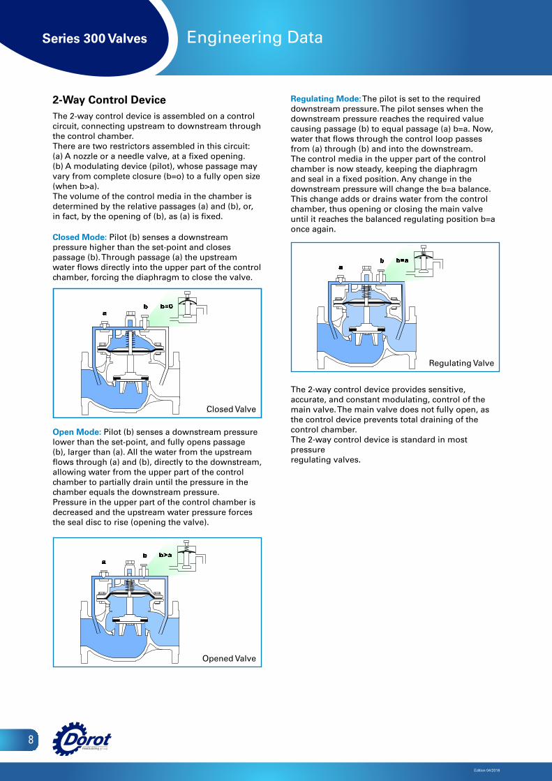
2-Way Control DeviceThe 2-way control device is assembled on a control circuit, connecting upstream to downstream through the control chamber.There are two restrictors assembled in this circuit:(a) A nozzle or a needle valve, at a fixed opening.(b) A modulating device (pilot), whose passage may vary from complete closure (b=o) to a fully open size (when b>a).The volume of the control media in the chamber is determined by the relative passages (a) and (b), or, in fact, by the opening of (b), as (a) is fixed.
Closed Mode: Pilot (b) senses a downstream pressure higher than the set-point and closes passage (b). Through passage (a) the upstream water flows directly into the upper part of the control chamber, forcing the diaphragm to close the valve.
Open Mode: Pilot (b) senses a downstream pressure lower than the set-point, and fully opens passage (b), larger than (a). All the water from the upstream flows through (a) and (b), directly to the downstream, allowing water from the upper part of the control chamber to partially drain until the pressure in the chamber equals the downstream pressure.Pressure in the upper part of the control chamber is decreased and the upstream water pressure forces the seal disc to rise (opening the valve).
Regulating Mode: The pilot is set to the required downstream pressure. The pilot senses when the downstream pressure reaches the required value causing passage (b) to equal passage (a) b=a. Now, water that flows through the control loop passes from (a) through (b) and into the downstream. The control media in the upper part of the control chamber is now steady, keeping the diaphragm and seal in a fixed position. Any change in the downstream pressure will change the b=a balance. This change adds or drains water from the control chamber, thus opening or closing the main valve until it reaches the balanced regulating position b=a once again.
The 2-way control device provides sensitive, accurate, and constant modulating, control of the main valve. The main valve does not fully open, as the control device prevents total draining of the control chamber.The 2-way control device is standard in most pressureregulating valves.
Closed Valve
Opened Valve
Closed Valve
Regulating Valve
Regulating Valve
Closed Mode
Open Mode
Closed Mode
Open Mode
Series 300 Valves
Edition 04/2018
9
Engineering Data
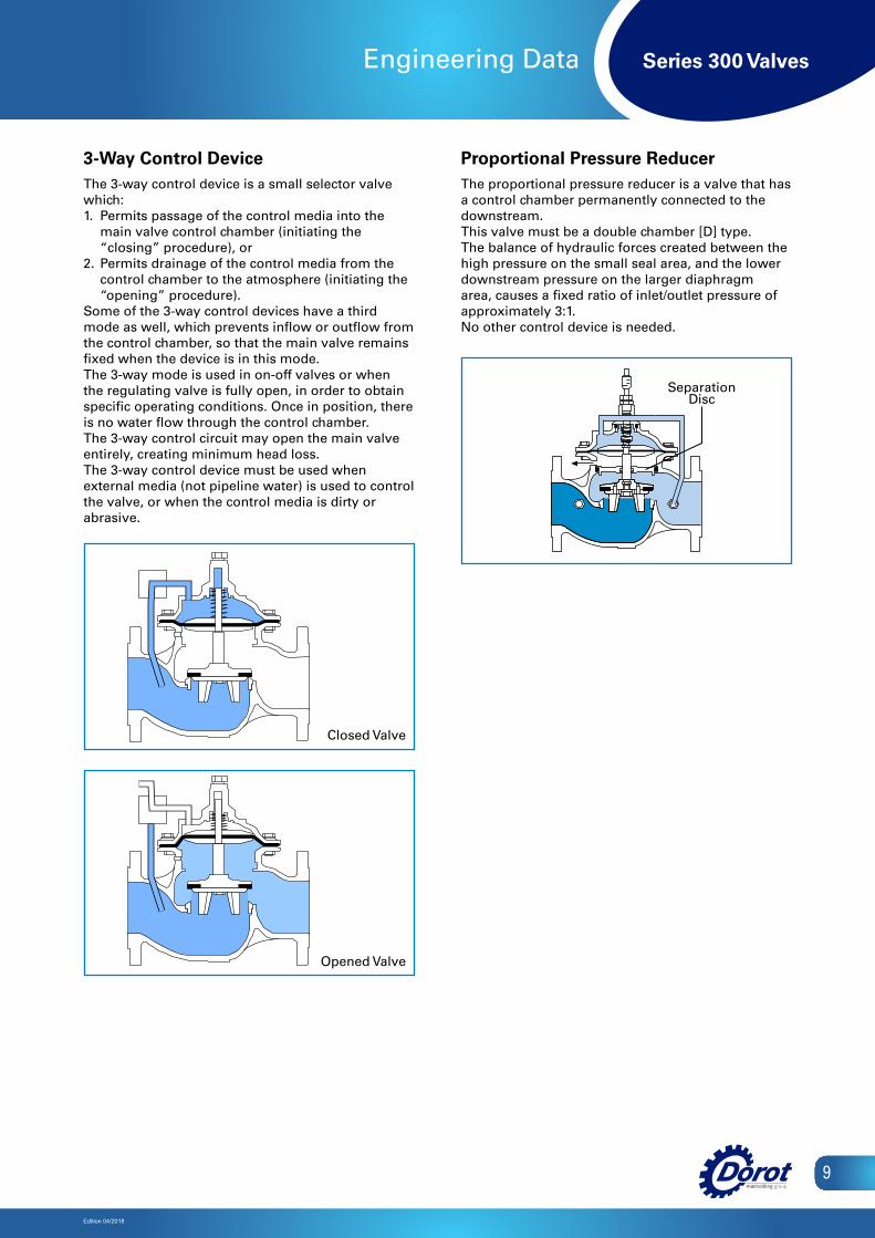
3-Way Control DeviceThe 3-way control device is a small selector valve which:1. Permits passage of the control media into the
main valve control chamber (initiating the “closing” procedure), or
2. Permits drainage of the control media from the control chamber to the atmosphere (initiating the “opening” procedure).
Some of the 3-way control devices have a third mode as well, which prevents inflow or outflow from the control chamber, so that the main valve remains fixed when the device is in this mode.The 3-way mode is used in on-off valves or when the regulating valve is fully open, in order to obtain specific operating conditions. Once in position, there is no water flow through the control chamber.The 3-way control circuit may open the main valve entirely, creating minimum head loss.The 3-way control device must be used when external media (not pipeline water) is used to control the valve, or when the control media is dirty or abrasive.
Proportional Pressure ReducerThe proportional pressure reducer is a valve that has a control chamber permanently connected to the downstream.This valve must be a double chamber [D] type.The balance of hydraulic forces created between the high pressure on the small seal area, and the lower downstream pressure on the larger diaphragm area, causes a fixed ratio of inlet/outlet pressure of approximately 3:1.No other control device is needed.
Closed Valve
Opened Valve
Pg .G3-d 3/3/02 11:50 Page 1
Composite
C M Y CM MY CY CMY K
2002G3-d
Non-Return (Check Valve) ModeDouble Chamber ValveFlow in the normal direction forces the seal to the "open"position, allowing for free flow. When downstream pressureexceeds upstream pressure, return flow may occur, causingthe seal disc to instantly close as a result of both hydraulicforce and the spring's force.
Proportional Pressure ReducerThe proportional pressure reducer is a valve that has a controlchamber permanently connected to the downstream.This valve must be a double chamber [D] type.The balance of hydraulic forces created between the highpressure on the small seal area, and the lower downstreampressure on the larger diaphragm area, causes a fixed ratioof inlet/outlet pressure of approximately 3:1.
No other control device is needed.
Regular Flow
Return Flow
Closed Valve
Open Valve
3-Way Control DeviceThe 3-way control device is a small selector valve which:1.Permits passage of the control media into the main valvecontrol chamber (initiating the "closing" procedure),or2. Permits drainage of the control media from the controlchamber to the atmosphere (initiating the "opening" procedure).
Some of the 3-way control devices have a third mode aswell, which prevents inflow or outflow from the controlchamber, so that the main valve remains fixed when thedevice is in this mode.This mode is used in on-off valves or when the regulatingvalve is fully open, in order to obtain specific operatingconditions. Once in position, there is no water flow throughthe control chamber.The 3-way control device may open the main valve entirely,creating minimum head loss.The 3-way control device must be used when external media(not pipeline water) is used to control the valve, or whenthe control media is abrasive.
Separation Disc
Closed Mode
Open Mode
Closed Mode
Open Mode
Series 300 Valves
10
Edition 04/2018
0
10
20
30
40
50
60
70
80
90
100
0 0.1 0.2 0.3 0.4 0.5 0.6 0.7KnKv
0
10
20
30
40
50
60
70
80
9.2.2001 10.2.2001 11.2.2001 12.2.2001 13.2.2001 14.2.2001 15.2.2001 16.2.20010
1
2
3
4
5
6
7
8
9
0.8 0.9 1.0
0
10
20
30
40
50
60
70
80
90
100
0 0.1 0.2 0.3 0.4 0.5 0.6 0.7KnKv
0
10
20
30
40
50
60
70
80
9.2.2001 10.2.2001 11.2.2001 12.2.2001 13.2.2001 14.2.2001 15.2.2001 16.2.20010
1
2
3
4
5
6
7
8
9
0.8 0.9 1.0
Engineering Data
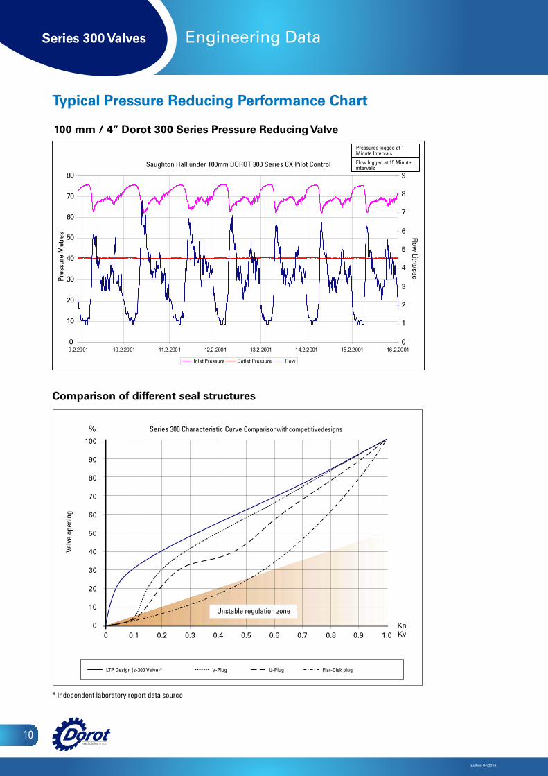
Typical Pressure Reducing Performance Chart
Comparison of different seal structures
100 mm / 4” Dorot 300 Series Pressure Reducing Valve
%
Unstable regulation zone
Pres
sure
Met
res
Outlet Pressure
* Independent laboratory report data source
Pressures logged at 1 Minute Intervals
Flow logged at 15 Minute intervals
Inlet Pressure
LTP Design (s-300 Valve)*
Saughton Hall under 100mm DOROT 300 Series CX Pilot Control
Flow Litre/sec
Flow
Valv
e op
enin
g
V-Plug U-Plug Flat-Disk plug
Series 300 Characteristic Curve Comparisonwithcompetitivedesigns

Series 300 Valves
Edition 04/2018
11
Engineering Data
Cavitation Data
10 20 30 40 50 60 70 80 mwc
Outlet pressure
10 30 50 60 70 90 100 110 psi 80 40 20
0
10
20
30
40
50
60
70
80
90
100
110
120
130
140
150
160
170
180
190
200
210
220
230
240
250
20
40
60
80
100
120
140
160
180
200
220
240
260
280
300
320
340
360 mwc psi
Inlet pressure
Case- III
Case- II
Case- I
Destructive Cavitation
Noisy Operating
Safe Operating conditions
Cavitation Chart Limits of operating conditionsThe chart above sets the safe limits for valves that are supposed to operate at a considerable pressure differential.Such conditions generate noise and possible cavitation damages to the valve body.How to use the chart:i. Determine the maximal dynamic pressure that may be applied in the inlet of the valve.ii. Draw an horizontal line from the pressure scale at the left side of the chartiii. Find the requested outlet pressure in the pressure scale at the bottom of the chart.iv. Draw an upward line at this point.v. The intersection of the two lines defines the cavitation characteristics of the valve operation.
- In the case that it falls in the RED zone (case I)- the valve may be damaged in a fairly short time.- In the case that it falls in the YELLOW zone (case II)- the valve may generate a noise that exceeds 80db.- In the case that the intersection is within the GREEN zone (case III)- the valve will perform safely and quietly
General remark: The cavitation and noise data are based on tests done by the Utah State University, US, and Delft Hydraulic Laboratories, Holland.
Inlet pressure
Outlet pressure
Destructive Cavitation
NoisyOperating
Case 1
Case 2
Case 3
Safe OperatingConditions
Series 300 Valves
Edition 04/2018
12
Engineering Data
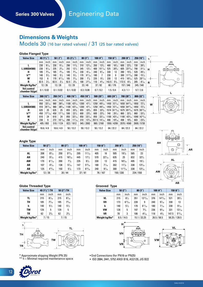
Dimensions & WeightsModels 30 (16 bar rated valves) / 31 (25 bar rated valves)
H
L
W
AH
AR
AL
TH
TR
TL
R
TW
AB
h h
AW
H
L
W
AH
AR
AL
TH
TR
TL
R
TW
AB
h h
AW
Globe Flanged Type Valve Size 40 (11/2”) 50 ( 2”) 65 (21/2”) 80 (3”) 100 (4”) 150 (6”) 200 (8”) 250 (10”)
mm inch mm inch mm inch mm inch mm inch mm inch mm inch mm inchL
L (ANSI#300)H
h**WR
23023018514015382.5
91/16
91/16
75/16
51/2
631/4
23023518514017082.5
91/16
23/16
75/16
51/2
611/16
31/4
29029218514018592.5
113/8
121/2
75/16
51/2
73/16
35/8
310345230170200100
123/16
131/2
91/16
611/16
77/8
315/16
350400240180235110
133/4
1511/16
97/16
791/4
45/16
480525330230330
142.5
187/8
205/8
1391355/8
600605390300415
172.5
235/8
2313/16
153/8
1113/16
165/16
63/4
730790520390525205
283/4
311/8
201/2
151/4
2011/16
81/16
Weight Kg/Ibs* 12 / 26 12 / 26 13 / 29 22 / 49 37 / 82 80 / 176 157 / 346 245 / 540Vol.control
chamber lit/gal 0.1 / 0.02 0.1 / 0.02 0.1 / 0.02 0.3 / 0.08 0.7 / 0.2 1.5 / 0.4 4.3 / 1.1 9.7 / 2.6
Valve Size 300 (12”) 350 (14”) 400 (16”) 450 (18”) 500 (20”) 600 (24”) 700 (28”) 800 (32”)mm inch mm inch mm inch mm inch mm inch mm inch mm inch mm inch
LL (ANSI#300)
Hh**WR
850910635450610230
337/16
3513/16
251711/16
249
980980635450610272
389/16
389/16
251711/16
241011/16
11001100855590850290
435/16
435/16
335/8
231/4
337/16
117/16
12001200855600850310
471/4
471/4
335/8
235/8
337/16
123/16
12501250855600850
357.5
493/16
493/16
335/8
235/8
337/16
141/16
1450145015747401100490
571/16
571/16
6115/16
291/8
435/16
195/16
1650165016758601100498
6415/16
6415/16
6515/16
337/8
435/16
195/8
1850185016758601090603
727/8
727/8
6515/16
337/8
4215/16
233/4
Weight Kg/Ibs* 405 / 893 510 / 1124 822 / 1812 945 / 2083 980 / 2160 1950 / 4299 2070 / 4560 2600 / 5730Vol.control
chamber lit/gal 18.6 / 4.9 18.6 / 4.9 50 / 13.2 50 / 13.2 50 / 13.2 84 / 22.2 84 / 22.2 84 / 22.2
Globe Threaded TypeValve Size 40 (11/2”) TH 50 (2”) TH
mm inch mm inchTL 215 87/16 215 87/16
TH 185 75/16 185 75/16
h 140 51/2 140 51/2
TW 129 5 129 5TR 62 23/8 62 23/8
Weight kg/lbs* 7 / 15 7 / 15
H
L
W
AH
AR
AL
TH
TR
TL
R
TW
AB
h h
AW
H
L
W
AH
AR
AL
TH
TR
TL
R
TW
AB
h h
AW
Angle TypeValve Size 50 (2”) 80 (3”) 100 (4”) 150 (6”) 200 (8”) 250 (10”)
mm inch mm inch mm inch mm inch mm inch mm inchAL 208 83/16 250 913/16 295 111/16 405 16 505 197/8 585 23AH 240 97/16 415 165/16 445 171/2 570 227/16 635 25 832 323/4
AW 170 611/16 200 77/8 235 91/4 330 13 415 165/16 495 191/2
AR 107 43/16 138 57/16 147 513/16 180 71/16 302 117/8 338 135/16
AB 125 415/16 150 57/8 173 613/16 240 97/16 300 1113/16 338 135/16
Weight kg/lbs* 12 / 26 20 / 44 37 / 81 76 / 167 150 / 330 234 / 550
H
L
W
AH
AR
AL
TH
TR
TL
R
TW
AB
h h
AW
H
L
W
AH
AR
AL
TH
TR
TL
R
TW
AB
h h
AW
Grooved TypeValve Size 50 (2”) 80 (3”) 100 (4”) 150 (6”)
mm inch mm inch mm inch mm inchVL 215 81/2 351 1313/16 376 1413/16 521 201/2
VH 173 613/16 228 9 240 97/16 330 13 h 140 51/2 170 611/16 180 71/16 230 91/16
VW 128 5 197 73/4 236 95/16 331 131/16
VR 78 3 106 43/16 118 45/8 147.5 513/16
Weight kg/lbs* 6.5 / 14.5 15.1 / 33.25 26.5 / 58.5 58.25 / 128.5VH
H
VRVH
H
VRVW
VL
VW
VL
* Approximate shipping Weight (PN 25) ** h = Minimal required maintenance space
• End Connections (for PN16 or PN25)• ISO 2084, 2441, 5752 ANSI B16, AS2129, JIS B22
Series 300 Valves
Edition 04/2018
13
Engineering Data
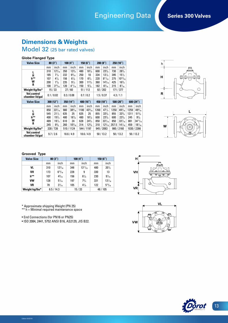
Dimensions & WeightsModel 32 (25 bar rated valves)
Globe Flanged TypeValve Size 80 (3”) 100 (4”) 150 (6”) 200 (8”) 250 (10”)
mm inch mm inch mm inch mm inch mm inch
LH
h**WR
310185107200100
123/16
71/4
41/4
77/8
315/16
350232156235120
133/4
93/16
61/8
91/4
411/16
480250170300150
187/8
10 63/4
113/4
57/8
600334220360182
235/8
131/8
811/16
143/16
63/16
730395275425215
283/4
151/2
1013/16
163/4
87/16
Weight Kg/Ibs* 15 / 33 27 / 60 51 / 112 92 / 202 171 / 377Vol.control
chamber lit/gal 0.1 / 0.02 0.3 / 0.08 0.7 / 0.2 1.5 / 0.37 4.3 / 1.1
Valve Size 300 (12”) 350 (14”) 400 (16”) 450 (18”) 500 (20”) 600 (24”)mm inch mm inch mm inch mm inch mm inch mm inch
LH
h**WR
850545400489245
337/16
211/2
153/4
191/4
93/8
980635480610260
389/16
25187/8
24103/16
1100635480628314
435/16
25187/8
243/4
123/8
1200855600850310
471/4
335/8
235/8
337/16
123/16
1250855600850
357.5
493/16
335/8
235/8
337/16
141/16
12591311245881459
499/16
515/8
95/8
3411/16
181/16
Weight Kg/Ibs* 330 / 726 510 / 1124 544 / 1197 945 / 2083 980 / 2160 1030 / 2266Vol.control
chamber lit/gal 9.7 / 2.6 18.6 / 4.9 18.6 / 4.9 50 / 13.2 50 / 13.2 50 / 13.2
Grooved TypeValve Size 80 (3”) 100 (4”) 150 (6”)
mm inch mm inch mm inchVL 310 123/16 348 1311/16 480 201/2
VH 173 613/16 228 9 330 13h** 107 43/16 156 61/8 230 91/16
VW 128 51/16 197 73/4 331 131/16
VR 78 31/16 105 41/8 122 513/16
Weight kg/lbs* 6.5 / 14.3 15 / 33 48 / 105
* Approximate shipping Weight (PN 25) ** h = Minimal required maintenance space
• End Connections (for PN16 or PN25) • ISO 2084, 2441, 5752 ANSI B16, AS2129, JIS B22.
H
L
W
AH
AR
AL
TH
TR
TL
R
TW
AB
h h
AW
H
L
W
AH
AR
AL
TH
TR
TL
R
TW
AB
h h
AW
VH
H
VRVH
H
VRVW
VL
VW
VL
Series 300 Valves
Edition 04/2018
14
Engineering Data
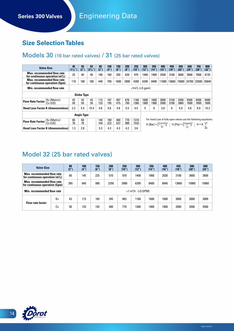
Model 32 (25 bar rated valves)
Valve Size 80(3”)
100(4”)
150(6”)
200(8”)
250(10”)
300(12”)
350(14”)
400(16”)
450(18”)
500(20”)
600(24”)
Max. recommended flow rate for continuous operation (m3/h) 60 145 225 510 970 1400 1900 2030 3100 3600 3600
Max. recommended flow rate for continuous operation (Gpm) 265 640 990 2250 3990 6200 8400 8940 13660 15860 15860
Min. recommended flow rate <1 m3/h (<5 GPM)
Flow rate factor:Kv 43 115 165 345 663 1160 1600 1600 3000 3000 3000
Cv 50 133 192 400 770 1360 1900 1900 3500 3500 3500
Size Selection Tables
Models 30 (16 bar rated valves) / 31 (25 bar rated valves)
Valve Size 40 (11/2”)
50 (2”)
65 (21/2”)
80 (3”)
100 (4”)
150 (6”)
200 (8”)
250 (10”)
300 (12”)
350 (14”)
400 (16”)
450 (18”)
500 (20”)
600 (24”)
700 (28”)
800 (32”)
Max. recommended flow rate for continuous operation (m3/h) 25 40 40 100 160 350 620 970 1400 1900 2500 3100 3600 5600 7600 8135
Max. recommended flow rate for continuous operation (Gpm) 110 180 180 440 700 1600 2800 4300 6200 8400 11000 13660 15800 24700 33500 35840
Min. recommended flow rate <1m3/h (<5 gpm)
Globe Type
Flow Rate Factor: Kv (Metric)Cv (US)
4350
4350
4350
115133
167195
407475
676790
11601360
16001900
16001900
30003500
31503700
33003860
65007600
65007600
65007600
Head Loss Factor K (dimensionless) 2.2 5.4 15.4 4.8 5.6 4.8 5.5 4.5 5 9 3.8 6 5.9 4.8 8.9 15.2
Angle Type
Flow Rate Factor: Kv (Metric)Cv (US)
6070
6070
140164
190222
460537
770900
13101533
Head Loss Factor K (dimensionless) 1.3 2.8 3.3 4.3 4.3 4.2 3.6
For head Loss of fully open valves use the following equations:
H (Bar) = (Q [m3/h])2 H (Psi) = (Q [gpm])2 H = K V2 Kv Cv 2g
Series 300 Valves
Edition 04/2018
15
Engineering Data
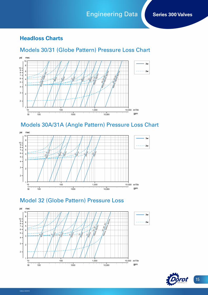
Headloss Charts
100 1000 10,000 gpm50
3w 2w
1
10
10 1,000
2
3
4
5
6
8
100 10,000 m3/hr
mwc
2
3
4
5
678
109
psi
3"80
mm
4 "10
0mm
6 "15
0mm
8 "20
0mm
10"
250m
m
24"
, 20
",
18"
450m
m,
50
0mm
,
600m
m
MODEL 32 (GLOBE PATTERN) PRESSURE LOSS CHART
12"
300m
m
16"
,14
"35
0mm
,
400m
m
w 3 w 2
1
0 1
0 0 0 , 1 0 1
2
3
4
5
6
8
0 0 1
001
0 0 0 , 0 1 m 3 r h / m p g
c w m
2
3
4
5 6 7 8
0 1 9
i s p
3 "
8 0 m
m
4 "
1 0 0 m
m
6 "
1 5 0 m
m
8 "
2 0 0 m
m
1 0 "
2 5 0 m
m 1 8
" , 2 0
" , 2 4
" 4 5
0 m m
, 5 0 0
m m
, 6 0 0
m m
T R A H C S S O L E R U S S E R P ) N R E T T A P E B O L G ( 2 3 L E D O M
1 2 "
3 0 0 m
m 1 4
" , 1 6 "
3 5
0 m m
, 4 0 0
m m
000,1 000,01
Model 32 (Globe Pattern) Pressure Loss
Models 30/31 (Globe Pattern) Pressure Loss Chart
Models 30A/31A (Angle Pattern) Pressure Loss Chart
w 3 w 2
1
0 1
0 0 0 , 1 0 1
2
3
4
5
6
8
0 0 1
001
0 0 0 , 0 1 m 3 r h / m p g
c w m
2
3
4
5 6 7 8
0 1 9
i s p
3 "
8 0 m
m
4 "
1 0 0 m
m
6 "
1 5 0 m
m
8 "
2 0 0 m
m
1 0 "
2 5 0 m
m 1 8
" , 2 0
" , 2 4
" 4 5
0 m m
, 5 0 0
m m
, 6 0 0
m m
T R A H C S S O L E R U S S E R P ) N R E T T A P E B O L G ( 2 3 L E D O M
1 2 "
3 0 0 m
m 1 4
" , 1 6 "
3 5
0 m m
, 4 0 0
m m
000,1 000,01
100 1000 10,000 gpm50
1
10
10 1,000
2
3
4
5
6
8
100 10,000 m3/hr
mwc
2
3
4
5
678
109
psi
2½"
, 2 ",
1½"
40m
m,
50m
m,
65m
m
3"80
mm
4"10
0mm
6 "15
0mm
8 "20
0mm
10"
250m
m 14"
, 12
"30
0mm
,
350
mm
20"
,18
",
16"
400m
m,
45
0mm
,
500
mm
32"
,28
",
24"
600m
m,
70
0mm
,
800
mm
MODELS 30 \ 31 (GLOBE PATTERN) PRESSURE LOSS CHART
3w 2w
1
10
10 1,000
2
3
4
5
6
8
100 10,000 m3/hr
mwc
2
3
4
5
678
109
psi
1½",
2 "40
mm
,
50m
m
3"80
mm
4"10
0mm
6 "15
0mm
8"20
0mm
MODELS 30A \ 31A (ANGLE PATTERN) PRESSURE LOSS CHART
10"
250m
m
3w 2w
100 1000 10,000 gpm50
w 3 w 2
1
0 1
0 0 0 , 1 0 1
2
3
4
5
6
8
0 0 1
001
0 0 0 , 0 1 m 3 r h / m p g
c w m
2
3
4
5 6 7 8
0 1 9
i s p
3 "
8 0 m
m
4 "
1 0 0 m
m
6 "
1 5 0 m
m
8 "
2 0 0 m
m
1 0 "
2 5 0 m
m 1 8
" , 2 0
" , 2 4
" 4 5
0 m m
, 5 0 0
m m
, 6 0 0
m m
T R A H C S S O L E R U S S E R P ) N R E T T A P E B O L G ( 2 3 L E D O M
1 2 "
3 0 0 m
m 1 4
" , 1 6 "
3 5
0 m m
, 4 0 0
m m
000,1 000,01
Series 300 Valves
Edition 04/2018
16
Engineering Data
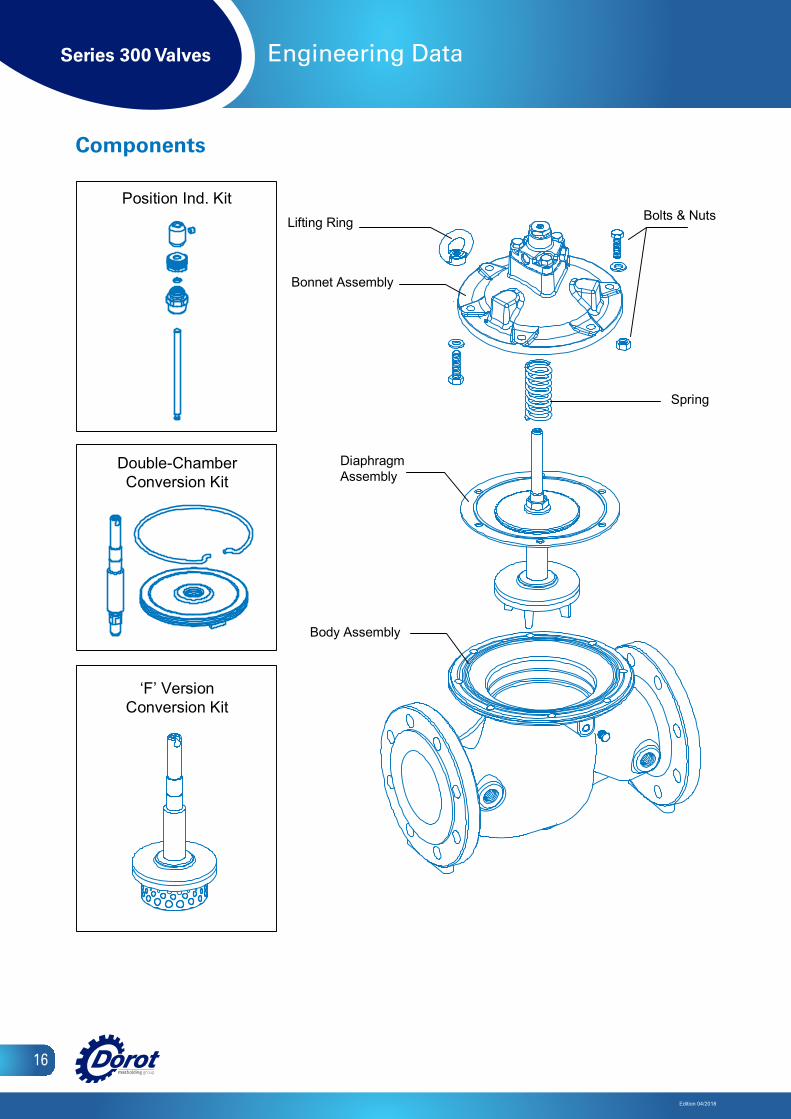
Components
DiaphragmAssembly
Bonnet Assembly
Body Assembly
Bolts & NutsLifting Ring
Spring
Position Ind. Kit
Double-ChamberConversion Kit
‘F’ VersionConversion Kit
Series 300 Valves
Edition 04/2018
17
Electronic and Remote control functions
S300 Features• Superb performance:
∙ Regulates at a stable mode, regardless of valve-size, down to near-zero flow. Thus, eliminating the need for a special low flow plug-design (such as ‘V-port’) or a bypass valve.
∙ ‘Floating’, low-friction internal-trim design, guided by unique LPT® device.
• High reliability: ∙ All control ports are fitted with SST sleeves for preventing
corrosion-blockage. ∙ Pre-shaped reinforced diaphragm – for easier assembly
and improved longevity.• Reduced periodic inspection/maintenance labor:
∙ The control-trim is fitted with a self-flushing, inline control-filter.
∙ Easy in-situ adjustment and maintenance. • Versatility:
∙ A standard and simple single-chamber valve design, provides smooth operation. Conversion to a double chamber is a patented option.
Standard Materials• Body & Cover – Ductile Iron
Optional – Cast Steel, SST, N.A.B, S.Duplex• Main Internal – SST (1.5”-6), Coated steel (8”-32”)
Optional – Cast Steel, SST, N.A.B, S.Duplex• Elastomers – EPDM
Optional – NBR, Neoprene, Viton or others• Coating – Polyester, Epoxy / Optional – Halar and others• Control trim – Brass, PA / Optional – SST316, Duplex
Purchase Specifications• The valve will be controlled by an electric solenoid valve. • Face-to-face length dimension meets ISO 5752 Standard.• The stem will be guided at the top by a replaceable guide
bearing and at the bottom by a stainless steel unique LPT® device.
• All control ports will be fitted with stainless steel sleeves for preventing corrosion-blockage.
Design Considerations• The valve should be suited for the maximal flow and allowed
Headloss.• Large pressure differentials may cause cavitation damage.
Consult Dorot for solutions if such conditions are expected.
Quick Sizing• Valve sized to be the same as line-size or one nominal-size
smaller.• Maximum recommended flow velocity for continuous
operation 5.5 m/sec (18 ft. /sec).
Pressure rating• Model 30, 30A for medium pressure (PN16 bar / 250 psi) • Model 31, 31A for high pressure (PN25 bar / 360 psi)
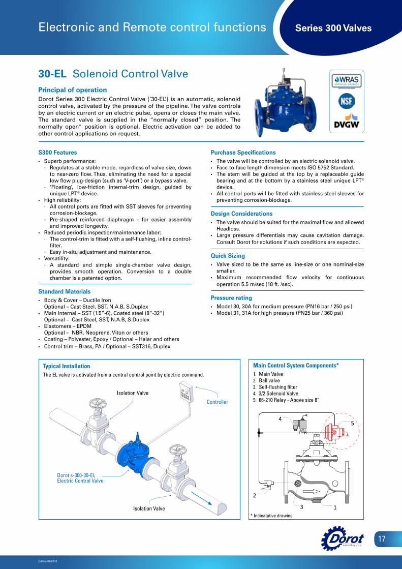
30-EL Solenoid Control ValvePrincipal of operationDorot Series 300 Electric Control Valve (’30-EL’) is an automatic, solenoid control valve, activated by the pressure of the pipeline. The valve controls by an electric current or an electric pulse, opens or closes the main valve. The standard valve is supplied in the “normally closed” position. The normally open” position is optional. Electric activation can be added to other control applications on request.
Controller
Isolation Valve
Isolation Valve
Dorot s-300-30-ELElectric Control Valve
Main Control System Components1 Main Valve2 Ball valve 3 Self-flushing filter 4 3/2 Solenoid Valve5 66-210 Relay – Above size 8"
13
2
45
Main Control System Components*1. Main Valve2. Ball valve3. Self-flushing filter4. 3/2 Solenoid Valve5. 66-210 Relay - Above size 8”
Typical InstallationThe EL valve is activated from a central control point by electric command.
* Indicatative drawing

Series 300 Valves
Edition 04/2018
18
Electronic and Remote control functions
S300 Features• Superb performance:
∙ Regulates at a stable mode, regardless of valve-size, down to near-zero flow. Thus, eliminating the need for a special low flow plug-design (such as ‘V-port’) or a bypass valve.
∙ ‘Floating’, low-friction internal-trim design, guided by unique LPT® device.
• High reliability: ∙ All control ports are fitted with SST sleeves for preventing
corrosion-blockage. ∙ Pre-shaped reinforced diaphragm – for easier assembly
and improved longevity.• Reduced periodic inspection/maintenance labor:
∙ The control-trim is fitted with a self-flushing, inline control-filter.
∙ Easy in-situ adjustment and maintenance. • Versatility:
∙ A standard and simple single-chamber valve design, provides smooth operation. Conversion to a double chamber is a patented option.
Standard Materials• Body & Cover – Ductile Iron
Optional – Cast Steel, SST, N.A.B, S.Duplex• Main Internal – SST (1.5”-6), Coated steel (8”-32”)
Optional – Cast Steel, SST, N.A.B, S.Duplex• Elastomers – EPDM
Optional – NBR, Neoprene, Viton or others• Coating – Polyester, Epoxy / Optional – Halar and others• Control trim – Brass, PA / Optional – SST316, Duplex
Purchase Specifications• The valve will be controlled by an electric solenoid valve. • Face-to-face length dimension meets ISO 5752 Standard.• The stem will be guided at the top by a replaceable guide
bearing and at the bottom by a stainless steel unique LPT® device.
• All control ports will be fitted with stainless steel sleeves for preventing corrosion-blockage.
Design Considerations• The valve should be suited for the maximal flow and allowed
Headloss.• Large pressure differentials may cause cavitation damage.
Consult Dorot for solutions if such conditions are expected.
Quick Sizing• Valve sized to be the same as line-size or one nominal-size
smaller.• Maximum recommended flow velocity for continuous
operation 5.5 m/sec (18 ft. /sec).
Pressure rating• Model 30, 30A for medium pressure (PN16 bar / 250 psi) • Model 31, 31A for high pressure (PN25 bar / 360 psi)
30-EL\ TO Two Stage Opening Solenoid Control ValvePrincipal of operation Dorot Series 300 Electric Control Valve (’30-EL\TO’) is an automatic, solenoid control valve, activated by the pressure of the pipeline. The valve controls by an electric current or an electric pulse, opens or closes the main valve. The ‘TO’ device prevents damage caused by too fast filling of a drained pipeline. The flow rate will be restricted, until the network, downstream of the valve is full and then a full opening of the valve is enabled.
*The ‘TO’ device can be added to any el control function.
Controller
Isolation Valve
Isolation Valve
Dorot s-300-30-EL\TOElectric Control Valve
Main Control System Components1 Main Valve2 Ball valve 3 Self-flushing filter 4 3/2 Solenoid Valve5 66-210 Relay – Above size 8" 6 3W PR Pilot Valve
13
2
45
6
Main Control System Components*1. Main Valve2. Ball valve3. Self-flushing filter4. 3/2 Solenoid Valve5. 66-210 Relay - Above size 8”6. 3W PR Pilot Valve
Typical InstallationThe EL\TO valve is activated from a central control point by electric command. The ‘TO’ device prevents damage caused by too fast filling of a drained pipeline
* Indicatative drawing
Series 300 Valves
Edition 04/2018
19
Electronic and Remote control functions
S300 Features• Superb performance:
∙ Regulates at a stable mode, regardless of valve-size, down to near-zero flow. Thus, eliminating the need for a special low flow plug-design (such as ‘V-port’) or a bypass valve.
∙ ‘Floating’, low-friction internal-trim design, guided by unique LPT® device.
• High reliability: ∙ All control ports are fitted with SST sleeves for preventing
corrosion-blockage. ∙ Pre-shaped reinforced diaphragm – for easier assembly
and improved longevity.• Reduced periodic inspection/maintenance labor:
∙ The control-trim is fitted with a self-flushing, inline control-filter.
∙ Easy in-situ adjustment and maintenance. • Versatility:
∙ A standard and simple single-chamber valve design, provides smooth operation. Conversion to a double chamber is a patented option.
Standard Materials• Body & Cover – Ductile Iron
Optional – Cast Steel, SST, N.A.B, S.Duplex• Main Internal – SST (1.5”-6), Coated steel (8”-32”)
Optional – Cast Steel, SST, N.A.B, S.Duplex• Elastomers – EPDM
Optional – NBR, Neoprene, Viton or others• Coating – Polyester, Epoxy / Optional – Halar and others• Control trim – Brass, PA / Optional – SST316, Duplex
Purchase Specifications• The valve will be controlled by an electric solenoid valves and
DOROT “ConDor” Controller. • Face-to-face length dimension meets ISO 5752 Standard.• The stem will be guided at the top by a replaceable guide
bearing and at the bottom by a stainless steel unique LPT®
device.• All control ports will be fitted with stainless steel sleeves for
preventing corrosion-blockage.
Design Considerations• The valve should be suited for the maximal flow and allowed
Headloss.• Large pressure differentials may cause cavitation damage.
Consult Dorot for solutions if such conditions are expected.
Quick Sizing• Valve sized to be the same as line-size or one nominal-size
smaller.• Maximum recommended flow velocity for continuous
operation 5.5 m/sec (18 ft. /sec).
Pressure rating• Model 30, 30A for medium pressure (PN16 bar / 250 psi) • Model 31, 31A for high pressure (PN25 bar / 360 psi)
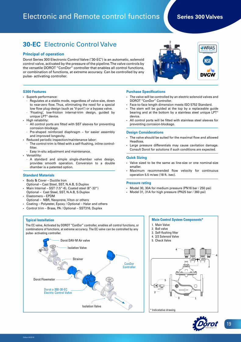
30-EC Electronic Control ValvePrincipal of operationDorot Series 300 Electronic Control Valve (’30-EC’) is an automatic, solenoid control valve, activated by the pressure of the pipeline. The valve controls by the versatile DOROT “ConDor” controller that enables all control functions, or combination of functions, at extreme accuracy. Can be controlled by any pulse- activating controller.
ConDor Controller
Isolation Valve
Strainer
Dorot DAV-M Air valve
Dorot Flowmeter
Isolation Valve
Dorot s-300-30-ECElectric Control Valve
13
2
21 21
5
4
4
Main Control System Components*1. Main Valve2. Ball valve3. Self-flushing filter4. 2/2 Solenoid Valve5. Check Valve
Typical InstallationThe EC valve, Activated by DOROT “ConDor” controller, enables all control functions, or combinations of functions, at extreme accuracy. The EC valve can be controlled by any pulse- activating controller.
* Indicatative drawing
Series 300 Valves
Edition 04/2018
20
Pressure regulating functions
S300 Features• Superb performance:
∙ Regulates at a stable mode, regardless of valve-size, down to near-zero flow. Thus, eliminating the need for a special low flow plug-design (such as ‘V-port’) or a bypass valve.
∙ ‘Floating’, low-friction internal-trim design, guided by unique LPT® device.
• High reliability: ∙ All control ports are fitted with SST sleeves for preventing
corrosion-blockage. ∙ Pre-shaped reinforced diaphragm – for easier assembly
and improved longevity.• Reduced periodic inspection/maintenance labor:
∙ The control-trim is fitted with a self-flushing, inline control-filter.
∙ Easy in-situ adjustment and maintenance. • Versatility:
∙ A standard and simple single-chamber valve design, provides smooth operation. Conversion to a double chamber is a patented option.
Standard Materials• Body & Cover – Ductile Iron
Optional – Cast Steel, SST, N.A.B, S.Duplex• Main Internal – SST (1.5”-6), Coated steel (8”-32”)
Optional – Cast Steel, SST, N.A.B, S.Duplex• Elastomers – EPDM
Optional – NBR, Neoprene, Viton or others• Coating – Polyester, Epoxy / Optional – Halar and others• Control trim – Brass, PA / Optional – SST316, Duplex
Purchase Specifications• The valve will be hydraulic, pilot-operated globe type.• Face-to-face length dimension meets ISO 5752 Standard.• The stem will be guided at the top by a replaceable guide
bearing and at the bottom by a stainless steel unique LPT®
device. • The valve will regulate any flow within the specified range
without the need for a smaller bypass valve or throttling plug.• All control ports will be corrosion free protected by stainless
steel 316 inserts.
Design Considerations• The valve should be suited for the maximal flow and allowed
Headloss.• In case upstream pressure may drop below the required set
pressure, select a 3-way control pilot.• Large pressure differentials may cause cavitation damage.
Consult Dorot for solutions if such conditions are expected.
Quick Sizing• Valve sized to be the same as line-size or one nominal-size
smaller.• Maximum recommended flow velocity for continuous
operation 5.5 m/sec (18 ft. /sec).
Pressure rating• Model 30, 30A for medium pressure (PN16 bar / 250 psi) • Model 31, 31A for high pressure (PN25 bar / 360 psi)
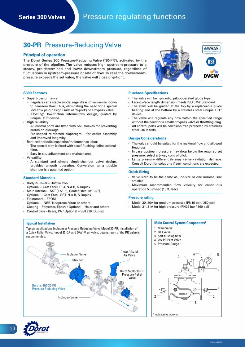
30-PR Pressure-Reducing ValvePrincipal of operationThe Dorot Series 300 Pressure-Reducing Valve (’30-PR’), activated by the pressure of the pipeline, The valve reduces high upstream-pressure to a steady, pre-determined and lower downstream pressure, regardless of fluctuations in upstream-pressure or rate of flow. In case the downstream-pressure exceeds the set value, the valve will close drip-tight.
Main Control System Components1 Main Valve2 Ball valve 3 Self-flushing filter 4 2W PR Pilot Valve5 Pressure Gauge
2
542
2
3 1
Main Control System Components*1. Main Valve2. Ball valve3. Self-flushing filter4. 2W PR Pilot Valve5. Pressure Gauge
Typical InstallationTypical applications Includes a Pressure Reducing Valve Model 30-PR. Installation of a Quick Relief Valve, model 30-QR and DAV-M air valve, downstream of the PR Valve is recommended.
Dorot DAV-M Air ValveIsolation Valve
Strainer
Isolation Valve
Dorot s-300-30-PRPressure Reducing Valve
Dorot S-300-30-QR Pressure Relief
Valve
* Indicatative drawing

Series 300 Valves
Edition 04/2018
21
Pressure regulating functions
S300 Features• Superb performance:
∙ Regulates at a stable mode, regardless of valve-size, down to near-zero flow. Thus, eliminating the need for a special low flow plug-design (such as ‘V-port’) or a bypass valve.
∙ ‘Floating’, low-friction internal-trim design, guided by unique LPT® device.
• High reliability: ∙ All control ports are fitted with SST sleeves for preventing
corrosion-blockage. ∙ Pre-shaped reinforced diaphragm – for easier assembly
and improved longevity.• Reduced periodic inspection/maintenance labor:
∙ The control-trim is fitted with a self-flushing, inline control-filter.
∙ Easy in-situ adjustment and maintenance. • Versatility:
∙ A standard and simple single-chamber valve design, provides smooth operation. Conversion to a double chamber is a patented option.
Standard Materials• Body & Cover – Ductile Iron
Optional – Cast Steel, SST, N.A.B, S.Duplex• Main Internal – SST (1.5”-6), Coated steel (8”-32”)
Optional – Cast Steel, SST, N.A.B, S.Duplex• Elastomers – EPDM
Optional – NBR, Neoprene, Viton or others• Coating – Polyester, Epoxy / Optional – Halar and others• Control trim – Brass, PA / Optional – SST316, Duplex
Purchase Specifications• Face-to-face length dimension meets ISO 5752 Standard.• The stem will be guided at the top by a replaceable guide
bearing and at the bottom by a stainless steel unique LPT®
device. • The valve will regulate any flow within the specified range
without the need for a smaller bypass valve or throttling plug.• All control ports will be corrosion free protected by stainless
steel 316 inserts.
Design Considerations• The valve should be suited for the maximal flow and allowed
Headloss.
Quick Sizing• Valve sized to be the same as line-size or one nominal-size
smaller.• Maximum recommended flow velocity for continuous
operation 5.5 m/sec (18 ft. /sec).
Pressure rating• Model 30, 30A for medium pressure (PN16 bar / 250 psi) • Model 31, 31A for high pressure (PN25 bar / 360 psi)
30-PR[D] Proportional Pressure-Reducing ValvePrincipal of operationThe Dorot Series 300 Proportional Pressure-Reducing Valve (’30-PR[D]’), is an automatic, proportional pressure-reducing valve. The valve is a double-chambered valve that will control the downstream pressure to vary in a fixed proportion in relation to the upstream pressure-value.
Isolation Valve
Strainer
Isolation Valve
Isolation Valve
Dorot s-300-30-PR[D]Differential Pressure Reducing Valve
Main Control System Components1 Main Valve2 Ball valve 3 Nozzle
2
3
1
Main Control System Components*1. Main Valve2. Ball valve3. Nozzle
Typical InstallationTypical applications Includes a Proportional Pressure Reducing Valve Model 30-PR[D]. Assembly of a PR[D] valve, upstream of a PR Valve, creates a two-stage, cavitation-free, pressure reducing station. Installation of a Quick Relief Valve, model 30-QR and DAV-M air valve, downstream of the PR Valve is recommended.
Dorot s-300-30-PRPressure Reducing Valve
Dorot s-300-30-QRPressure Relief Valve
Dorot DAV-M Air Valve
* Indicatative drawing

Series 300 Valves
Edition 04/2018
22
Pressure regulating functions
Dorot DAV-M Air ValveIsolation Valve
Strainer
Isolation Valve
Dorot s-300-30-PRM[E2]Pressure Reducing Valve
Dorot S-300-30-QR Pressure Relief
Valve
S300 Features• Superb performance:
∙ Regulates at a stable mode, regardless of valve-size, down to near-zero flow. Thus, eliminating the need for a special low flow plug-design (such as ‘V-port’) or a bypass valve.
∙ ‘Floating’, low-friction internal-trim design, guided by unique LPT® device.
• High reliability: ∙ All control ports are fitted with SST sleeves for preventing
corrosion-blockage. ∙ Pre-shaped reinforced diaphragm – for easier assembly
and improved longevity.• Reduced periodic inspection/maintenance labor:
∙ The control-trim is fitted with a self-flushing, inline control-filter.
∙ Easy in-situ adjustment and maintenance. • Versatility:
∙ A standard and simple single-chamber valve design, provides smooth operation. Conversion to a double chamber is a patented option.
Standard Materials• Body & Cover – Ductile Iron
Optional – Cast Steel, SST, N.A.B, S.Duplex• Main Internal – SST (1.5”-6), Coated steel (8”-32”)
Optional – Cast Steel, SST, N.A.B, S.Duplex• Elastomers – EPDM
Optional – NBR, Neoprene, Viton or others• Coating – Polyester, Epoxy / Optional – Halar and others• Control trim – Brass, PA / Optional – SST316, Duplex
Purchase Specifications• The valve will be hydraulic, pilot-operated globe type.• Face-to-face length dimension meets ISO 5752 Standard.• The stem will be guided at the top by a replaceable guide
bearing and at the bottom by a stainless steel unique LPT®
device. • The valve will regulate any flow within the specified range
without the need for a smaller bypass valve or throttling plug.• All control ports will be corrosion free protected by stainless
steel 316 inserts.
Design Considerations• The valve should be suited for the maximal flow and allowed
Headloss.• In case upstream pressure may drop below the required set
pressure, select a 3-way control pilot.• Large pressure differentials may cause cavitation damage.
Consult Dorot for solutions if such conditions are expected.
Quick Sizing• Valve sized to be the same as line-size or one nominal-size
smaller.• Maximum recommended flow velocity for continuous
operation 5.5 m/sec (18 ft. /sec).
Pressure rating• Model 30, 30A for medium pressure (PN16 bar / 250 psi) • Model 31, 31A for high pressure (PN25 bar / 360 psi)
30-PRM Dual Set-Point Pressure-Reducing ValvePrincipal of operationThe Dorot Series 300 Duel set-point Pressure-Reducing (’30-PRM’) valve, isan automatic, pilot controlled pressure reducing valve.The valve will regulate downstream pressure to one of two set-values.The set-value is selected by an hydraulic command sent to the control-trimof the valve. Both pressure values can be easily adjusted by the user.
Main Control System Components1 Main Valve2 Ball valve 3 Self-flushing filter 4 2W PRM Pilot Valve5 Pressure Gauge
3 1
22
24
5
Main Control System Components*1. Main Valve2. Ball valve3. Self-flushing filter4. 2W PRM Pilot Valve5. Pressure Gauge
Typical InstallationTypical applications Includes a Pressure Reducing Valve Model 30-PRM Installation of a Quick Relief Valve, model 30-QR and DAV-M air valve, downstream of the PR Valve is recommended.
* Indicatative drawing
Series 300 Valves
Edition 04/2018
23
Pressure regulating functions
Features• Superb performance:
∙ Regulates at a stable mode, regardless of valve-size, down to near-zero flow. Thus, eliminating the need for a special low flow plug-design (such as ‘V-port’) or a bypass valve.
∙ ‘Floating’, low-friction internal-trim design, guided by unique LPT® device.
• High reliability: ∙ All control ports are fitted with SST sleeves for preventing
corrosion-blockage. ∙ Pre-shaped reinforced diaphragm – for easier assembly
and improved longevity.• Reduced periodic inspection/maintenance labor:
∙ The control-trim is fitted with a self-flushing, inline control-filter.
∙ Easy in-situ adjustment and maintenance. • Versatility:
∙ A standard and simple single-chamber valve design, provides smooth operation. Conversion to a double chamber is a patented option.
Standard Materials• Body & Cover – Ductile Iron
Optional – Cast Steel, SST, N.A.B, S.Duplex• Main Internal – SST (1.5”-6), Coated steel (8”-32”)
Optional – Cast Steel, SST, N.A.B, S.Duplex• Elastomers – EPDM
Optional – NBR, Neoprene, Viton or others• Coating – Polyester, Epoxy / Optional – Halar and others• Control trim – Brass, PA / Optional – SST316, Duplex
Purchase Specifications• The valve will be hydraulic, pilot-operated globe type.• Face-to-face length dimension meets ISO 5752 Standard.• The stem will be guided at the top by a replaceable guide
bearing and at the bottom by a stainless steel unique LPT®
device.• The valve will regulate any flow within the specified range
without the need for a smaller bypass valve or throttling plug.• All control ports will be corrosion free protected by stainless
steel 316 inserts.
Design Considerations• The valve should be suited for the maximal flow and allowed
Headloss.• In case upstream pressure may drop below the required
set pressure, select a 3-way control pilot.• Large pressure differentials may cause cavitation
damage. Consult Dorot for solutions if such conditions are expected.
Quick Sizing• Valve sized to be the same as line-size or one nominal-size
smaller.• Maximum recommended flow velocity for continuous
operation 5.5 m/sec (18 ft. /sec).
Pressure rating• Model 30, 30A for medium pressure (PN16 bar / 250 psi) • Model 31, 31A for high pressure (PN25 bar / 360 psi)
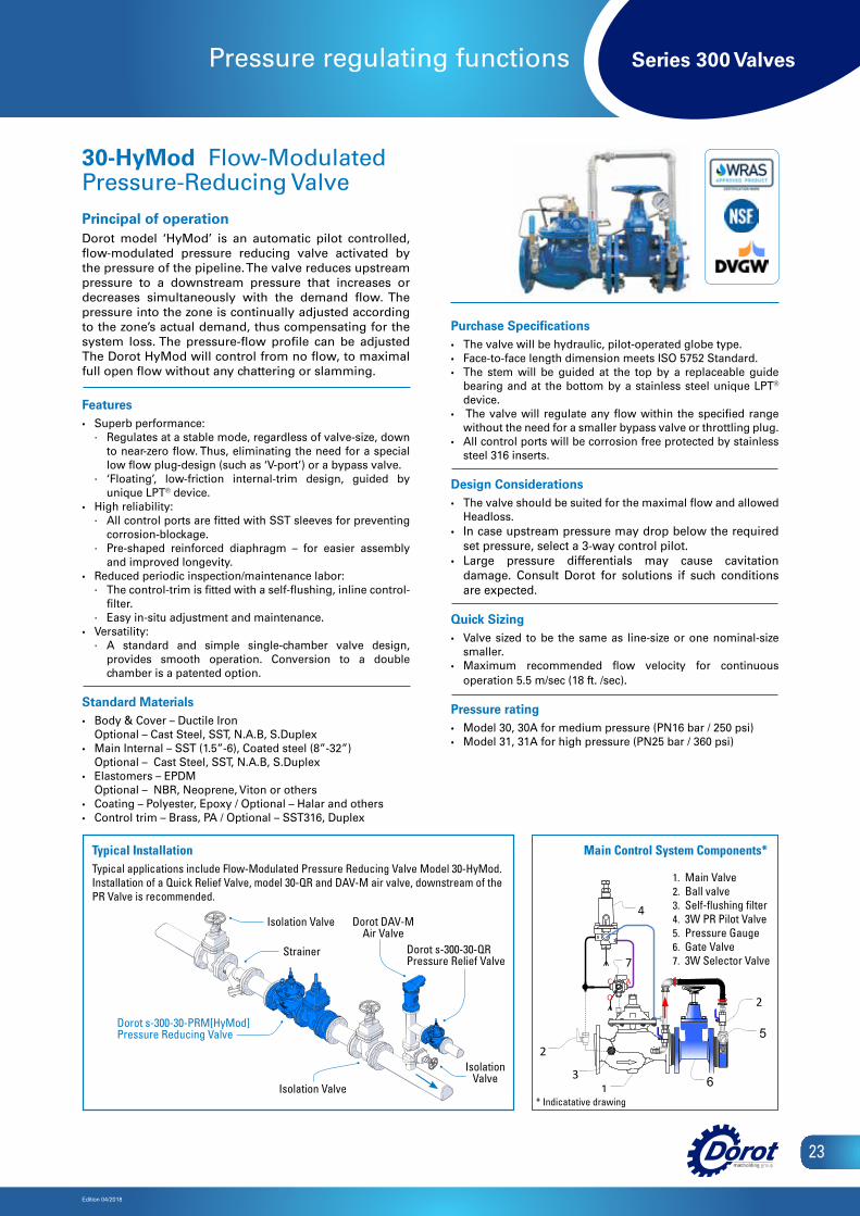
30-HyMod Flow-Modulated Pressure-Reducing ValvePrincipal of operationDorot model ‘HyMod’ is an automatic pilot controlled, flow-modulated pressure reducing valve activated by the pressure of the pipeline. The valve reduces upstream pressure to a downstream pressure that increases or decreases simultaneously with the demand flow. The pressure into the zone is continually adjusted according to the zone’s actual demand, thus compensating for the system loss. The pressure-flow profile can be adjusted The Dorot HyMod will control from no flow, to maximal full open flow without any chattering or slamming.
AC
O
1
2
3
4
2
5
6
7
Main Control System Components*Typical InstallationTypical applications include Flow-Modulated Pressure Reducing Valve Model 30-HyMod. Installation of a Quick Relief Valve, model 30-QR and DAV-M air valve, downstream of the PR Valve is recommended.
1. Main Valve2. Ball valve3. Self-flushing filter4. 3W PR Pilot Valve5. Pressure Gauge6. Gate Valve7. 3W Selector Valve
Strainer
Isolation Valve
Isolation Valve
Dorot s-300-30-PRM[HyMod]Pressure Reducing Valve
Dorot s-300-30-QRPressure Relief Valve
Dorot DAV-M Air Valve
Isolation Valve
* Indicatative drawing
Series 300 Valves
Edition 04/2018
24
Pressure regulating functions
S300 Features• Superb performance:
∙ Regulates at a stable mode, regardless of valve-size, down to near-zero flow. Thus, eliminating the need for a special low flow plug-design (such as ‘V-port’) or a bypass valve.
∙ ‘Floating’, low-friction internal-trim design, guided by unique LPT® device.
• High reliability: ∙ All control ports are fitted with SST sleeves for preventing
corrosion-blockage. ∙ Pre-shaped reinforced diaphragm – for easier assembly
and improved longevity.• Reduced periodic inspection/maintenance labor:
∙ The control-trim is fitted with a self-flushing, inline control-filter.
∙ Easy in-situ adjustment and maintenance. • Versatility:
∙ A standard and simple single-chamber valve design, provides smooth operation. Conversion to a double chamber is a patented option.
Standard Materials• Body & Cover – Ductile Iron
Optional – Cast Steel, SST, N.A.B, S.Duplex• Main Internal – SST (1.5”-6), Coated steel (8”-32”)
Optional – Cast Steel, SST, N.A.B, S.Duplex• Elastomers – EPDM
Optional – NBR, Neoprene, Viton or others• Coating – Polyester, Epoxy / Optional – Halar and others• Control trim – Brass, PA / Optional – SST316, Duplex
Purchase Specifications• The valve will be hydraulic, pilot-operated globe type.• Face-to-face length dimension meets ISO 5752 Standard.• The stem will be guided at the top by a replaceable guide• bearing and at the bottom by a stainless steel unique LPT®
device. • The valve will regulate any flow within the specified range
without the need for a smaller bypass valve or throttling plug.• All control ports will be corrosion free protected by stainless
steel 316 inserts.
Design Considerations• The valve should be suited for the maximal flow and allowed
Headloss.• Large pressure differentials may cause cavitation damage.
Consult Dorot for solutions if such conditions are expected.
Quick Sizing• Valve sized to be the same as line-size or one nominal-size
smaller.• Maximum recommended flow velocity for continuous
operation 5.5 m/sec (18 ft. /sec).
Pressure rating• Model 30, 30A for medium pressure (PN16 bar / 250 psi) • Model 31, 31A for high pressure (PN25 bar / 360 psi)
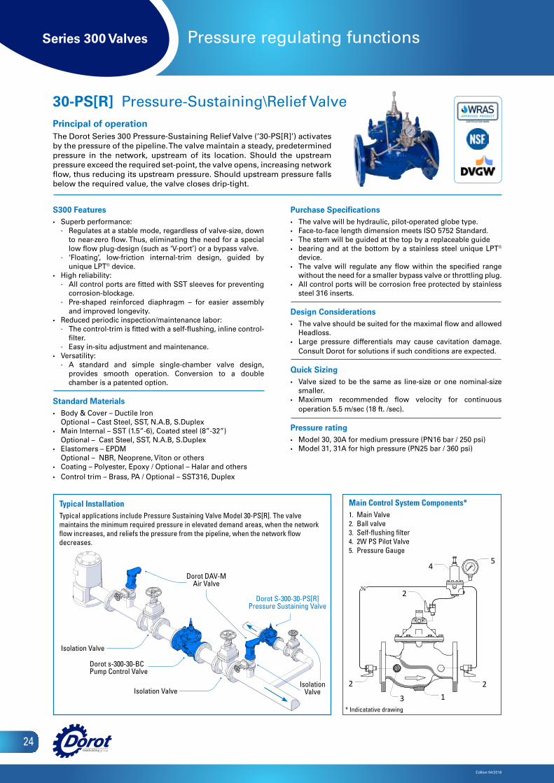
30-PS[R] Pressure-Sustaining\Relief ValvePrincipal of operationThe Dorot Series 300 Pressure-Sustaining Relief Valve (’30-PS[R]’) activates by the pressure of the pipeline. The valve maintain a steady, predetermined pressure in the network, upstream of its location. Should the upstream pressure exceed the required set-point, the valve opens, increasing network flow, thus reducing its upstream pressure. Should upstream pressure falls below the required value, the valve closes drip-tight.
Main Control System Components1 Main Valve2 Ball valve 3 Self-flushing filter 4 2W PR Pilot Valve5 Pressure Gauge
2
54
2
2
3 1
⅜"
Main Control System Components*1. Main Valve2. Ball valve3. Self-flushing filter4. 2W PS Pilot Valve5. Pressure Gauge
Typical InstallationTypical applications include Pressure Sustaining Valve Model 30-PS[R]. The valve maintains the minimum required pressure in elevated demand areas, when the network flow increases, and reliefs the pressure from the pipeline, when the network flow decreases.
Dorot DAV-M Air Valve
Isolation ValveIsolation
Valve
Dorot s-300-30-BCPump Control Valve
Dorot S-300-30-PS[R] Pressure Sustaining Valve
Isolation Valve
* Indicatative drawing

Series 300 Valves
Edition 04/2018
25
Pressure regulating functions
S300 Features• Superb performance:
∙ Regulates at a stable mode, regardless of valve-size, down to near-zero flow. Thus, eliminating the need for a special low flow plug-design (such as ‘V-port’) or a bypass valve.
∙ ‘Floating’, low-friction internal-trim design, guided by unique LPT® device.
• High reliability: ∙ All control ports are fitted with SST sleeves for preventing
corrosion-blockage. ∙ Pre-shaped reinforced diaphragm – for easier assembly
and improved longevity.• Reduced periodic inspection/maintenance labor:
∙ The control-trim is fitted with a self-flushing, inline control-filter.
∙ Easy in-situ adjustment and maintenance. • Versatility:
∙ A standard and simple single-chamber valve design, provides smooth operation. Conversion to a double chamber is a patented option.
Standard Materials• Body & Cover – Ductile Iron
Optional – Cast Steel, SST, N.A.B, S.Duplex• Main Internal – SST (1.5”-6), Coated steel (8”-32”)
Optional – Cast Steel, SST, N.A.B, S.Duplex• Elastomers – EPDM
Optional – NBR, Neoprene, Viton or others• Coating – Polyester, Epoxy / Optional – Halar and others• Control trim – Brass, PA / Optional – SST316, Duplex
Purchase Specifications• The valve will be hydraulic, pilot-operated globe type.• Face-to-face length dimension meets ISO 5752 Standard.• The stem will be guided at the top by a replaceable guide
bearing and at the bottom by a stainless steel unique LPT®
device. • The valve will regulate any flow within the specified range
without the need for a smaller bypass valve or throttling plug.• All control ports will be corrosion free protected by stainless
steel 316 inserts.
Design Considerations• The valve should be suited for the maximal flow and allowed
Headloss.• For low pressure systems, consider a 3-way control pilots.• Large pressure differentials may cause cavitation
damage. Consult Dorot for solutions if such conditions are expected.
Quick Sizing• Valve sized to be the same as line-size or one nominal-size
smaller.• Maximum recommended flow velocity for continuous
operation 5.5 m/sec (18 ft. /sec).
Pressure rating• Model 30, 30A for medium pressure (PN16 bar / 250 psi) • Model 31, 31A for high pressure (PN25 bar / 360 psi)
30-PS Pressure Sustaining ValvePrincipal of operationThe Dorot Series 300 Pressure-Sustaining Valve (’30-PS’) activates by the pressure of the pipeline. The valve maintains a steady, predetermined pressure in the network, upstream of its location. Should the upstream pressure exceed the required set-point, the valve opens, increasing network flow, thus reducing its upstream pressure. If upstream pressure falls below the required value, the valve closes drip-tight.
Isolation Valve
Dorot s-300-30-PSPressure Sustaining Valve
Main Control System Components1 Main Valve2 Ball valve 3 Self-flushing filter 4 2W PS Pilot Valve5 Pressure Gauge
2
54
2
2
3 1
⅜"
Main Control System Components*1. Main Valve2. Ball valve3. Self-flushing filter4. 2W PS Pilot Valve5. Pressure Gauge
Typical InstallationTypical applications include Pressure Sustaining Valve Model 30-PS. The valve will maintain a steady, predetermined pressure in the network, upstream of its location.
Dorot DAV-MH-SA Air Valve
* Indicatative drawing
Series 300 Valves
Edition 04/2018
26
Pressure regulating functions
S300 Features• Superb performance:
∙ Regulates at a stable mode, regardless of valve-size, down to near-zero flow. Thus, eliminating the need for a special low flow plug-design (such as ‘V-port’) or a bypass valve.
∙ ‘Floating’, low-friction internal-trim design, guided by unique LPT® device.
• High reliability: ∙ All control ports are fitted with SST sleeves for preventing
corrosion-blockage. ∙ Pre-shaped reinforced diaphragm – for easier assembly
and improved longevity.• Reduced periodic inspection/maintenance labor:
∙ The control-trim is fitted with a self-flushing, inline control-filter.
∙ Easy in-situ adjustment and maintenance. • Versatility:
∙ A standard and simple single-chamber valve design, provides smooth operation. Conversion to a double chamber is a patented option.
Standard Materials• Body & Cover – Ductile Iron
Optional – Cast Steel, SST, N.A.B, S.Duplex• Main Internal – SST (1.5”-6), Coated steel (8”-32”)
Optional – Cast Steel, SST, N.A.B, S.Duplex• Elastomers – EPDM
Optional – NBR, Neoprene, Viton or others• Coating – Polyester, Epoxy / Optional – Halar and others• Control trim – Brass, PA / Optional – SST316, Duplex
Purchase Specifications• The valve will be hydraulic, pilot-operated globe type.• Face-to-face length dimension meets ISO 5752 Standard.• The stem will be guided at the top by a replaceable guide• bearing and at the bottom by a stainless steel unique LPT®
device. • The valve will regulate any flow within the specified range
without the need for a smaller bypass valve or throttling plug.• All control ports will be corrosion free protected by stainless
steel 316 inserts.
Design Considerations• The valve should be suited for the maximal flow and allowed
Headloss.• For low pressure systems, consider a 3-way control pilots.• Large pressure differentials may cause cavitation damage.
Consult Dorot for solutions if such conditions are expected.
Quick Sizing• Valve sized to be the same as line-size or one nominal-size
smaller.• Maximum recommended flow velocity for continuous
operation 5.5 m/sec (18 ft. /sec).
Pressure rating• Model 30, 30A for medium pressure (PN16 bar / 250 psi) • Model 31, 31A for high pressure (PN25 bar / 360 psi)
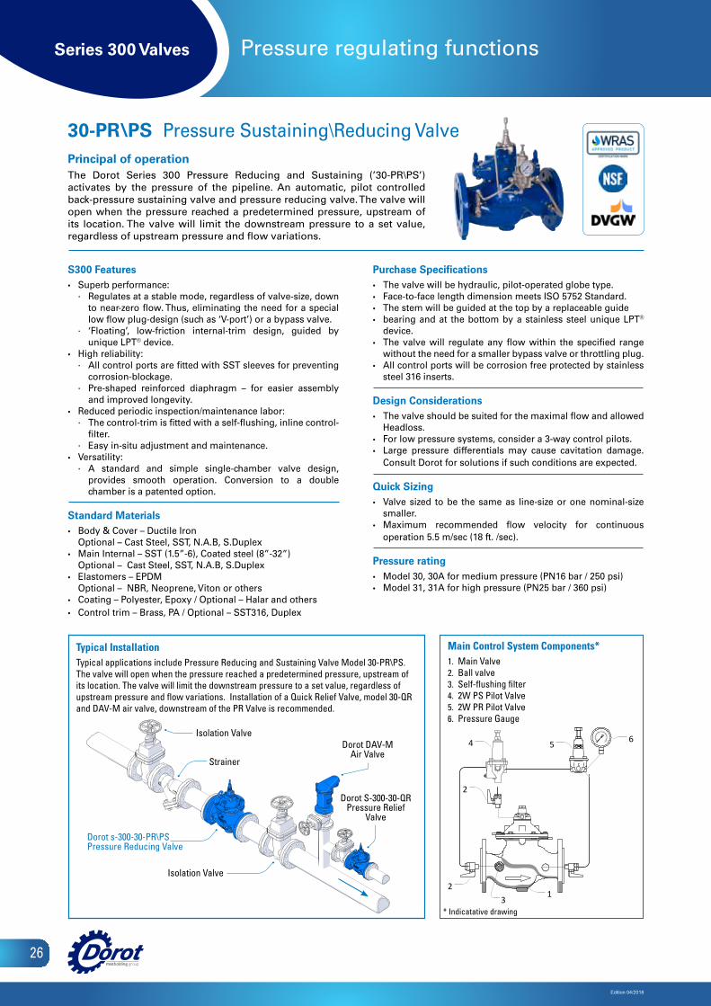
30-PR\ PS Pressure Sustaining\Reducing ValvePrincipal of operationThe Dorot Series 300 Pressure Reducing and Sustaining (’30-PR\PS’) activates by the pressure of the pipeline. An automatic, pilot controlled back-pressure sustaining valve and pressure reducing valve. The valve will open when the pressure reached a predetermined pressure, upstream of its location. The valve will limit the downstream pressure to a set value, regardless of upstream pressure and flow variations.
Main Control System Components
1 Main Valve 4 2W PS Pilot Valve2 Ball valve 5 2W PR Pilot Valve 3 Self-flushing filter 6 Pressure Gauge
23
1
2
4 5 6
Main Control System Components*1. Main Valve2. Ball valve3. Self-flushing filter4. 2W PS Pilot Valve5. 2W PR Pilot Valve6. Pressure Gauge
Typical InstallationTypical applications include Pressure Reducing and Sustaining Valve Model 30-PR\PS. The valve will open when the pressure reached a predetermined pressure, upstream of its location. The valve will limit the downstream pressure to a set value, regardless of upstream pressure and flow variations. Installation of a Quick Relief Valve, model 30-QR and DAV-M air valve, downstream of the PR Valve is recommended.
* Indicatative drawing
Dorot DAV-M Air Valve
Isolation Valve
Strainer
Isolation Valve
Dorot s-300-30-PR\PSPressure Reducing Valve
Dorot S-300-30-QR Pressure Relief
Valve
Series 300 Valves
Edition 04/2018
27
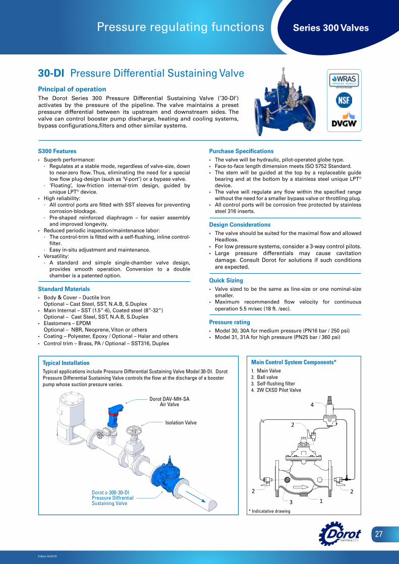
Pressure regulating functions
S300 Features• Superb performance:
∙ Regulates at a stable mode, regardless of valve-size, down to near-zero flow. Thus, eliminating the need for a special low flow plug-design (such as ‘V-port’) or a bypass valve.
∙ ‘Floating’, low-friction internal-trim design, guided by unique LPT® device.
• High reliability: ∙ All control ports are fitted with SST sleeves for preventing
corrosion-blockage. ∙ Pre-shaped reinforced diaphragm – for easier assembly
and improved longevity.• Reduced periodic inspection/maintenance labor:
∙ The control-trim is fitted with a self-flushing, inline control-filter.
∙ Easy in-situ adjustment and maintenance. • Versatility:
∙ A standard and simple single-chamber valve design, provides smooth operation. Conversion to a double chamber is a patented option.
Standard Materials• Body & Cover – Ductile Iron
Optional – Cast Steel, SST, N.A.B, S.Duplex• Main Internal – SST (1.5”-6), Coated steel (8”-32”)
Optional – Cast Steel, SST, N.A.B, S.Duplex• Elastomers – EPDM
Optional – NBR, Neoprene, Viton or others• Coating – Polyester, Epoxy / Optional – Halar and others• Control trim – Brass, PA / Optional – SST316, Duplex
Purchase Specifications• The valve will be hydraulic, pilot-operated globe type.• Face-to-face length dimension meets ISO 5752 Standard.• The stem will be guided at the top by a replaceable guide
bearing and at the bottom by a stainless steel unique LPT®
device. • The valve will regulate any flow within the specified range
without the need for a smaller bypass valve or throttling plug.• All control ports will be corrosion free protected by stainless
steel 316 inserts.
Design Considerations• The valve should be suited for the maximal flow and allowed
Headloss.• For low pressure systems, consider a 3-way control pilots.• Large pressure differentials may cause cavitation
damage. Consult Dorot for solutions if such conditions are expected.
Quick Sizing• Valve sized to be the same as line-size or one nominal-size
smaller.• Maximum recommended flow velocity for continuous
operation 5.5 m/sec (18 ft. /sec).
Pressure rating• Model 30, 30A for medium pressure (PN16 bar / 250 psi) • Model 31, 31A for high pressure (PN25 bar / 360 psi)
30-DI Pressure Differential Sustaining ValvePrincipal of operationThe Dorot Series 300 Pressure Differential Sustaining Valve (’30-DI’) activates by the pressure of the pipeline. The valve maintains a preset pressure differential between its upstream and downstream sides. The valve can control booster pump discharge, heating and cooling systems, bypass configurations,filters and other similar systems.
Main Control System Components1 Main Valve2 Ball valve 3 Self-flushing filter 4 2W CXSD Pilot Valve
2
4
2
2
3 1
⅜"
Main Control System Components*1. Main Valve2. Ball valve3. Self-flushing filter4. 2W CXSD Pilot Valve
Typical InstallationTypical applications include Pressure Differential Sustaining Valve Model 30-DI. Dorot Pressure Differential Sustaining Valve controls the flow at the discharge of a booster pump whose suction pressure varies.
* Indicatative drawing
Isolation Valve
Dorot s-300-30-DIPressure Diffrential Sustaining Valve
Dorot DAV-MH-SA Air Valve
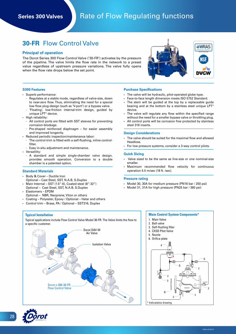
Series 300 Valves
Edition 04/2018
28
Rate of Flow Regulating functions
S300 Features• Superb performance:
∙ Regulates at a stable mode, regardless of valve-size, down to near-zero flow. Thus, eliminating the need for a special low flow plug-design (such as ‘V-port’) or a bypass valve.
∙ ‘Floating’, low-friction internal-trim design, guided by unique LPT® device.
• High reliability: ∙ All control ports are fitted with SST sleeves for preventing
corrosion-blockage. ∙ Pre-shaped reinforced diaphragm – for easier assembly
and improved longevity.• Reduced periodic inspection/maintenance labor:
∙ The control-trim is fitted with a self-flushing, inline control-filter.
∙ Easy in-situ adjustment and maintenance. • Versatility:
∙ A standard and simple single-chamber valve design, provides smooth operation. Conversion to a double chamber is a patented option.
Standard Materials• Body & Cover – Ductile Iron
Optional – Cast Steel, SST, N.A.B, S.Duplex• Main Internal – SST (1.5”-6), Coated steel (8”-32”)
Optional – Cast Steel, SST, N.A.B, S.Duplex• Elastomers – EPDM
Optional – NBR, Neoprene, Viton or others• Coating – Polyester, Epoxy / Optional – Halar and others• Control trim – Brass, PA / Optional – SST316, Duplex
Purchase Specifications• The valve will be hydraulic, pilot-operated globe type.• Face-to-face length dimension meets ISO 5752 Standard.• The stem will be guided at the top by a replaceable guide
bearing and at the bottom by a stainless steel unique LPT®
device. • The valve will regulate any flow within the specified range
without the need for a smaller bypass valve or throttling plug.• All control ports will be corrosion free protected by stainless
steel 316 inserts.
Design Considerations• The valve should be suited for the maximal flow and allowed
Headloss.• For low pressure systems, consider a 3-way control pilots.
Quick Sizing• Valve sized to be the same as line-size or one nominal-size
smaller. • Maximum recommended flow velocity for continuous
operation 5.5 m/sec (18 ft. /sec).
Pressure rating• Model 30, 30A for medium pressure (PN16 bar / 250 psi) • Model 31, 31A for high pressure (PN25 bar / 360 psi)
30-FR Flow Control ValvePrincipal of operationThe Dorot Series 300 Flow Control Valve (’30-FR’) activates by the pressure of the pipeline. The valve limits the flow rate in the network to a preset value regardless of upstream pressure variations. The valve fully opens when the flow rate drops below the set point.
1 Main Valve2 Ball valve 3 Self-flushing filter
2
61
2
2
4
5
5
2
Main Control System Components
3
Main Control System Components*1. Main Valve2. Ball valve3. Self-flushing filter4. CXSD Pilot Valve5. Nozzle6. Orifice plate
Typical InstallationTypical applications include Flow Control Valve Model 30-FR. The Valve limits the flow to a specific customer.
Dorot DAV-M Air Valve
Isolation Valve
Dorot s-300-30-FRFlow Control Valve
* Indicatative drawing
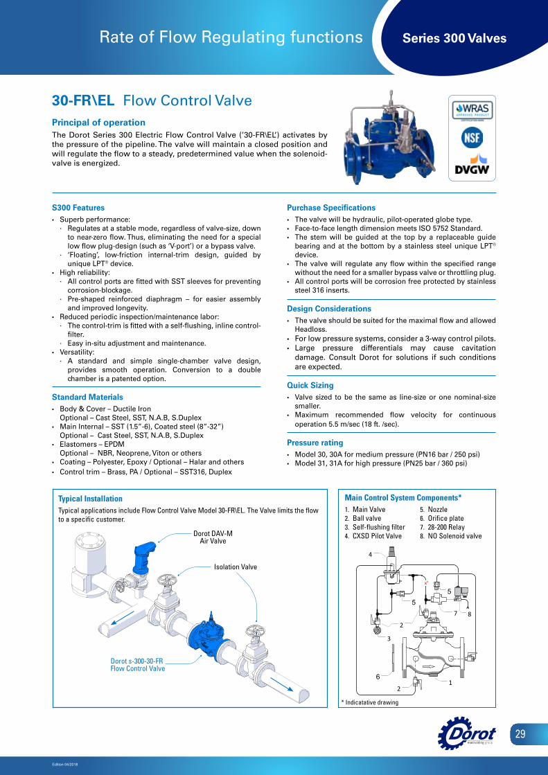
Series 300 Valves
Edition 04/2018
29
Rate of Flow Regulating functions
S300 Features• Superb performance:
∙ Regulates at a stable mode, regardless of valve-size, down to near-zero flow. Thus, eliminating the need for a special low flow plug-design (such as ‘V-port’) or a bypass valve.
∙ ‘Floating’, low-friction internal-trim design, guided by unique LPT® device.
• High reliability: ∙ All control ports are fitted with SST sleeves for preventing
corrosion-blockage. ∙ Pre-shaped reinforced diaphragm – for easier assembly
and improved longevity.• Reduced periodic inspection/maintenance labor:
∙ The control-trim is fitted with a self-flushing, inline control-filter.
∙ Easy in-situ adjustment and maintenance. • Versatility:
∙ A standard and simple single-chamber valve design, provides smooth operation. Conversion to a double chamber is a patented option.
Standard Materials• Body & Cover – Ductile Iron
Optional – Cast Steel, SST, N.A.B, S.Duplex• Main Internal – SST (1.5”-6), Coated steel (8”-32”)
Optional – Cast Steel, SST, N.A.B, S.Duplex• Elastomers – EPDM
Optional – NBR, Neoprene, Viton or others• Coating – Polyester, Epoxy / Optional – Halar and others• Control trim – Brass, PA / Optional – SST316, Duplex
Purchase Specifications• The valve will be hydraulic, pilot-operated globe type.• Face-to-face length dimension meets ISO 5752 Standard.• The stem will be guided at the top by a replaceable guide
bearing and at the bottom by a stainless steel unique LPT®
device. • The valve will regulate any flow within the specified range
without the need for a smaller bypass valve or throttling plug.• All control ports will be corrosion free protected by stainless
steel 316 inserts.
Design Considerations• The valve should be suited for the maximal flow and allowed
Headloss.• For low pressure systems, consider a 3-way control pilots.• Large pressure differentials may cause cavitation
damage. Consult Dorot for solutions if such conditions are expected.
Quick Sizing• Valve sized to be the same as line-size or one nominal-size
smaller.• Maximum recommended flow velocity for continuous
operation 5.5 m/sec (18 ft. /sec).
Pressure rating• Model 30, 30A for medium pressure (PN16 bar / 250 psi) • Model 31, 31A for high pressure (PN25 bar / 360 psi)
30-FR\ EL Flow Control ValvePrincipal of operationThe Dorot Series 300 Electric Flow Control Valve (’30-FR\EL’) activates by the pressure of the pipeline. The valve will maintain a closed position and will regulate the flow to a steady, predetermined value when the solenoid-valve is energized.
Main Control System Components
1 Main Valve2 Ball valve 3 Self-flushing filter
4 CXSD Pilot Valve5 Nozzle 6 Orifice plate 7 28-200 Relay8 NO Solenoid valve
x"
2
61
5
2
4
3
2
57 8
Main Control System Components*1. Main Valve2. Ball valve3. Self-flushing filter4. CXSD Pilot Valve
Typical InstallationTypical applications include Flow Control Valve Model 30-FR\EL. The Valve limits the flow to a specific customer.
5. Nozzle6. Orifice plate7. 28-200 Relay8. NO Solenoid valveDorot DAV-M
Air Valve
Isolation Valve
Dorot s-300-30-FRFlow Control Valve
* Indicatative drawing
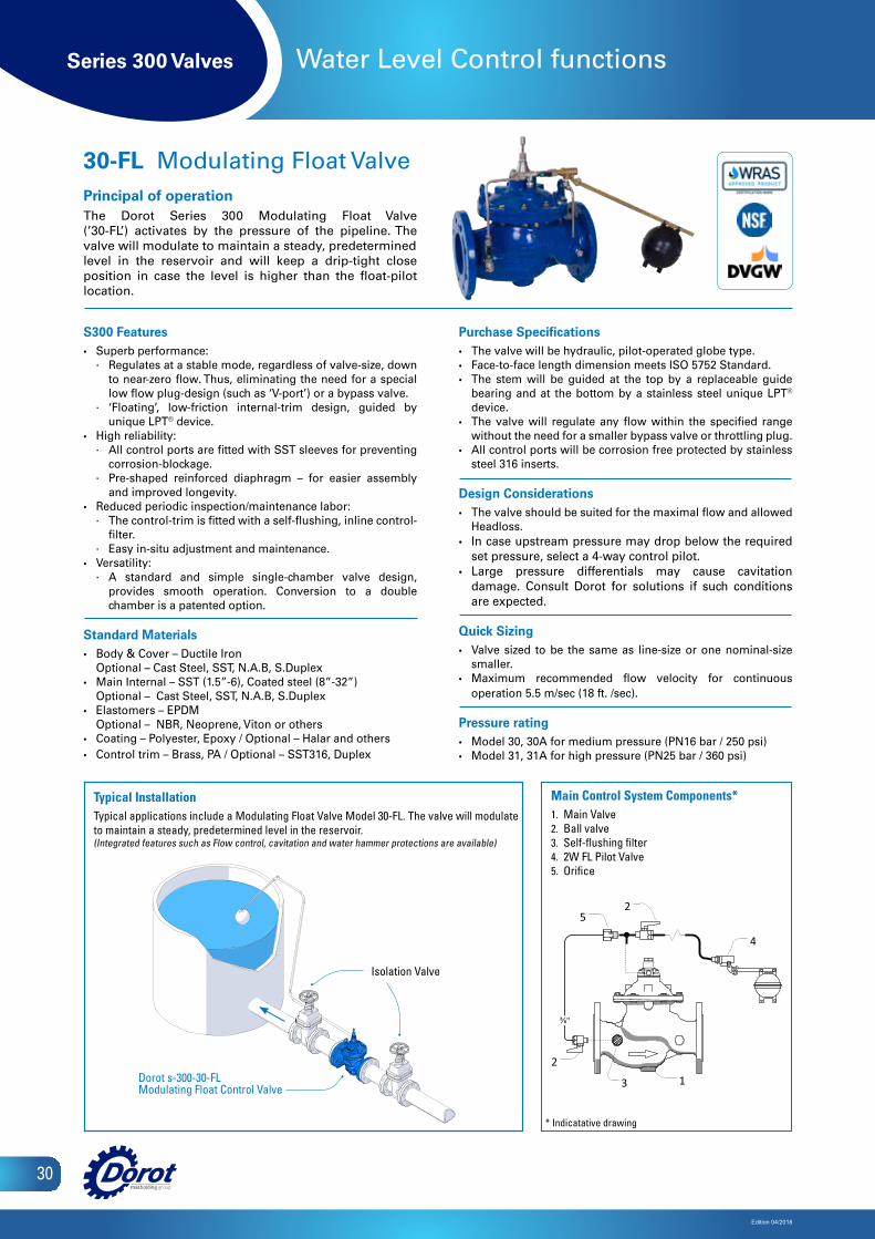
Series 300 Valves
Edition 04/2018
30
Water Level Control functions
S300 Features• Superb performance:
∙ Regulates at a stable mode, regardless of valve-size, down to near-zero flow. Thus, eliminating the need for a special low flow plug-design (such as ‘V-port’) or a bypass valve.
∙ ‘Floating’, low-friction internal-trim design, guided by unique LPT® device.
• High reliability: ∙ All control ports are fitted with SST sleeves for preventing
corrosion-blockage. ∙ Pre-shaped reinforced diaphragm – for easier assembly
and improved longevity.• Reduced periodic inspection/maintenance labor:
∙ The control-trim is fitted with a self-flushing, inline control-filter.
∙ Easy in-situ adjustment and maintenance. • Versatility:
∙ A standard and simple single-chamber valve design, provides smooth operation. Conversion to a double chamber is a patented option.
Standard Materials• Body & Cover – Ductile Iron
Optional – Cast Steel, SST, N.A.B, S.Duplex• Main Internal – SST (1.5”-6), Coated steel (8”-32”)
Optional – Cast Steel, SST, N.A.B, S.Duplex• Elastomers – EPDM
Optional – NBR, Neoprene, Viton or others• Coating – Polyester, Epoxy / Optional – Halar and others• Control trim – Brass, PA / Optional – SST316, Duplex
Purchase Specifications• The valve will be hydraulic, pilot-operated globe type.• Face-to-face length dimension meets ISO 5752 Standard.• The stem will be guided at the top by a replaceable guide
bearing and at the bottom by a stainless steel unique LPT®
device. • The valve will regulate any flow within the specified range
without the need for a smaller bypass valve or throttling plug.• All control ports will be corrosion free protected by stainless
steel 316 inserts.
Design Considerations• The valve should be suited for the maximal flow and allowed
Headloss.• In case upstream pressure may drop below the required
set pressure, select a 4-way control pilot.• Large pressure differentials may cause cavitation
damage. Consult Dorot for solutions if such conditions are expected.
Quick Sizing• Valve sized to be the same as line-size or one nominal-size
smaller.• Maximum recommended flow velocity for continuous
operation 5.5 m/sec (18 ft. /sec).
Pressure rating• Model 30, 30A for medium pressure (PN16 bar / 250 psi) • Model 31, 31A for high pressure (PN25 bar / 360 psi)
30-FL Modulating Float ValvePrincipal of operationThe Dorot Series 300 Modulating Float Valve (’30-FL’) activates by the pressure of the pipeline. The valve will modulate to maintain a steady, predeterminedlevel in the reservoir and will keep a drip-tight close position in case the level is higher than the float-pilot location.
Main Control System Components1 Main Valve2 Ball valve 3 Self-flushing filter 4 2W FL Pilot Valve5 Orifice
5
4
2
2
3 1
⅜"
Main Control System Components*1. Main Valve2. Ball valve3. Self-flushing filter4. 2W FL Pilot Valve5. Orifice
Typical InstallationTypical applications include a Modulating Float Valve Model 30-FL. The valve will modulate to maintain a steady, predetermined level in the reservoir. (Integrated features such as Flow control, cavitation and water hammer protections are available)
Isolation Valve
Dorot s-300-30-FLModulating Float Control Valve
* Indicatative drawing
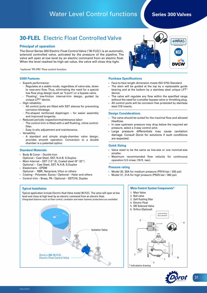
Series 300 Valves
Edition 04/2018
31
Water Level Control functions
S300 Features• Superb performance:
∙ Regulates at a stable mode, regardless of valve-size, down to near-zero flow. Thus, eliminating the need for a special low flow plug-design (such as ‘V-port’) or a bypass valve.
∙ ‘Floating’, low-friction internal-trim design, guided by unique LPT® device.
• High reliability: ∙ All control ports are fitted with SST sleeves for preventing
corrosion-blockage. ∙ Pre-shaped reinforced diaphragm – for easier assembly
and improved longevity.• Reduced periodic inspection/maintenance labor:
∙ The control-trim is fitted with a self-flushing, inline control-filter.
∙ Easy in-situ adjustment and maintenance. • Versatility:
∙ A standard and simple single-chamber valve design, provides smooth operation. Conversion to a double chamber is a patented option.
Standard Materials• Body & Cover – Ductile Iron
Optional – Cast Steel, SST, N.A.B, S.Duplex• Main Internal – SST (1.5”-6), Coated steel (8”-32”)
Optional – Cast Steel, SST, N.A.B, S.Duplex• Elastomers – EPDM
Optional – NBR, Neoprene, Viton or others• Coating – Polyester, Epoxy / Optional – Halar and others• Control trim – Brass, PA / Optional – SST316, Duplex
Purchase Specifications• Face-to-face length dimension meets ISO 5752 Standard. • The stem will be guided at the top by a replaceable guide
bearing and at the bottom by a stainless steel unique LPT® device.
• The valve will regulate any flow within the specified range without the need for a smaller bypass valve or throttling plug.
• All control ports will be corrosion free protected by stainless steel 316 inserts.
Design Considerations• The valve should be suited for the maximal flow and allowed
Headloss.• In case upstream pressure may drop below the required set
pressure, select a 3-way control pilot.• Large pressure differentials may cause cavitation
damage. Consult Dorot for solutions if such conditions are expected.
Quick Sizing• Valve sized to be the same as line-size or one nominal-size
smaller.• Maximum recommended flow velocity for continuous
operation 5.5 m/sec (18 ft. /sec).
Pressure rating• Model 30, 30A for medium pressure (PN16 bar / 250 psi) • Model 31, 31A for high pressure (PN25 bar / 360 psi)
30-FLEL Electric Float Controlled ValvePrincipal of operationThe Dorot Series 300 Electric Float Control Valve (’30-FLEL’) is an automatic, solenoid controlled valve, activated by the pressure of the pipeline. The valve will open at low level by an electric command from an electric float. When the level reached its high set value, the valve will close drip tight.
*optional ‘FR (PR)’ Flow control function.
Main Control System Components*1. Main Valve2. Ball valve3. Self-flushing filter4. Electric Float5. 3W Solenoid Valve6. Orifice (Optional)
Main Control System Components1 Main Valve2 Ball valve 3 Self-flushing filter 4 Electric Float5 3W Solenoid Valve
6. Orifice(Optional)
21
Control-Panel(by customer)
13
2
45
6
Isolation Valve
Dorot s-300-30-FLELElectric Float Control Valve
* Indicatative drawing
Typical InstallationTypical application include Electric float Valve model 30-FLEL. The valve will open at low level and close at high level by an electric command from an electric float. (Integrated features such as Flow control, cavitation and water hammer protections are available)
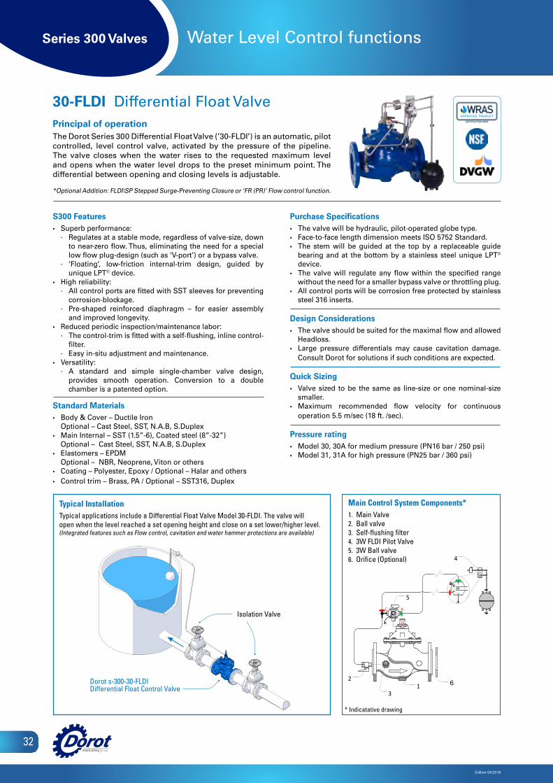
Series 300 Valves
Edition 04/2018
32
Water Level Control functions
S300 Features• Superb performance:
∙ Regulates at a stable mode, regardless of valve-size, down to near-zero flow. Thus, eliminating the need for a special low flow plug-design (such as ‘V-port’) or a bypass valve.
∙ ‘Floating’, low-friction internal-trim design, guided by unique LPT® device.
• High reliability: ∙ All control ports are fitted with SST sleeves for preventing
corrosion-blockage. ∙ Pre-shaped reinforced diaphragm – for easier assembly
and improved longevity.• Reduced periodic inspection/maintenance labor:
∙ The control-trim is fitted with a self-flushing, inline control-filter.
∙ Easy in-situ adjustment and maintenance. • Versatility:
∙ A standard and simple single-chamber valve design, provides smooth operation. Conversion to a double chamber is a patented option.
Standard Materials• Body & Cover – Ductile Iron
Optional – Cast Steel, SST, N.A.B, S.Duplex• Main Internal – SST (1.5”-6), Coated steel (8”-32”)
Optional – Cast Steel, SST, N.A.B, S.Duplex• Elastomers – EPDM
Optional – NBR, Neoprene, Viton or others• Coating – Polyester, Epoxy / Optional – Halar and others• Control trim – Brass, PA / Optional – SST316, Duplex
Purchase Specifications• The valve will be hydraulic, pilot-operated globe type. • Face-to-face length dimension meets ISO 5752 Standard.• The stem will be guided at the top by a replaceable guide
bearing and at the bottom by a stainless steel unique LPT®
device.• The valve will regulate any flow within the specified range
without the need for a smaller bypass valve or throttling plug.• All control ports will be corrosion free protected by stainless
steel 316 inserts.
Design Considerations• The valve should be suited for the maximal flow and allowed
Headloss.• Large pressure differentials may cause cavitation damage.
Consult Dorot for solutions if such conditions are expected.
Quick Sizing• Valve sized to be the same as line-size or one nominal-size
smaller.• Maximum recommended flow velocity for continuous
operation 5.5 m/sec (18 ft. /sec).
Pressure rating• Model 30, 30A for medium pressure (PN16 bar / 250 psi) • Model 31, 31A for high pressure (PN25 bar / 360 psi)
30-FLDI Differential Float ValvePrincipal of operationThe Dorot Series 300 Differential Float Valve (’30-FLDI’) is an automatic, pilot controlled, level control valve, activated by the pressure of the pipeline. The valve closes when the water rises to the requested maximum level and opens when the water level drops to the preset minimum point. The differential between opening and closing levels is adjustable.
*Optional Addition: FLDI\SP Stepped Surge-Preventing Closure or ‘FR (PR)’ Flow control function.
5
4
2
AC
O
Main Control System Components1 Main Valve2 Ball valve 3 Self-flushing filter 4 3W FLDI Pilot Valve5 3W Ball valve
6. Orifice(Optional)
31 6
Main Control System Components*1. Main Valve2. Ball valve3. Self-flushing filter4. 3W FLDI Pilot Valve5. 3W Ball valve6. Orifice (Optional)
Typical InstallationTypical applications include a Differential Float Valve Model 30-FLDI. The valve will open when the level reached a set opening height and close on a set lower/higher level. (Integrated features such as Flow control, cavitation and water hammer protections are available)
Isolation Valve
Dorot s-300-30-FLDIDifferential Float Control Valve
* Indicatative drawing

Series 300 Valves
Edition 04/2018
33
Water Level Control functions
S300 Features• Superb performance:
∙ Regulates at a stable mode, regardless of valve-size, down to near-zero flow. Thus, eliminating the need for a special low flow plug-design (such as ‘V-port’) or a bypass valve.
∙ ‘Floating’, low-friction internal-trim design, guided by unique LPT® device.
• High reliability: ∙ All control ports are fitted with SST sleeves for preventing
corrosion-blockage. ∙ Pre-shaped reinforced diaphragm – for easier assembly
and improved longevity.• Reduced periodic inspection/maintenance labor:
∙ The control-trim is fitted with a self-flushing, inline control-filter.
∙ Easy in-situ adjustment and maintenance. • Versatility:
∙ A standard and simple single-chamber valve design, provides smooth operation. Conversion to a double chamber is a patented option.
Standard Materials• Body & Cover – Ductile Iron
Optional – Cast Steel, SST, N.A.B, S.Duplex• Main Internal – SST (1.5”-6), Coated steel (8”-32”)
Optional – Cast Steel, SST, N.A.B, S.Duplex• Elastomers – EPDM
Optional – NBR, Neoprene, Viton or others• Coating – Polyester, Epoxy / Optional – Halar and others• Control trim – Brass, PA / Optional – SST316, Duplex
Purchase Specifications• The valve will be hydraulic, pilot-operated globe type.• Face-to-face length dimension meets ISO 5752 Standard. • The stem will be guided at the top by a replaceable guide
bearing and at the bottom by a stainless steel unique LPT® device.
• The valve will regulate any flow within the specified range without the need for a smaller bypass valve or throttling plug.
• All control ports will be corrosion free protected by stainless steel 316 inserts.
Design Considerations• The valve should be suited for the maximal flow and allowed
Headloss.• For low pressure systems, consider a 3-way control pilots.• Large pressure differentials may cause cavitation
damage. Consult Dorot for solutions if such conditions are expected.
Quick Sizing• Valve sized to be the same as line-size or one nominal-size
smaller.• Maximum recommended flow velocity for continuous
operation 5.5 m/sec (18 ft. /sec).
Pressure rating• Model 30, 30A for medium pressure (PN16 bar / 250 psi) • Model 31, 31A for high pressure (PN25 bar / 360 psi)
30-FLDI\ PS Differential Float and Pressure Sustaining ValvePrincipal of operationThe Dorot Series 300 Differential Float and Pressure sustaining Valve (’30-FLDI\PS’) is An automatic, float actuated and pressure sustaining pilot controlled valve. The valve will open and sustain a minimal required up-stream-pressure when the level reached a set opening height and close on a set lower\higher level. The differential between opening and closing levels is adjustable. In case the upstream pressure is lower than the set-value, the valve will keep a closed position, regardless of the water-level.
4
6
AC
O
7
5
1
2
3
8
Main Control System Components1 Main Valve2 Ball valve 3 Self-flushing filter 4 3W FLDI Pilot Valve5 3W Ball valve6. Orifice (Optional)7. 31-10SD Pilot8. Pressure gauge
Main Control System Components*1. Main Valve2. Ball valve3. Self-flushing filter4. 3W FLDI Pilot Valve5. 3W Ball valve6. Orifice (Optional)7. 31-10SD Pilot8. Pressure gauge
Isolation Valve
Dorot s-300-30-FLDI\PSDifferential Float and Pressure Sustaining Valve
* Indicatative drawing
Typical InstallationTypical applications include a Differential Float Valve Model 30-FLDI\PS. The valve will open and sustain a minimal required upstream-pressure when the level reached a set opening height and close on a set lower/higher level.
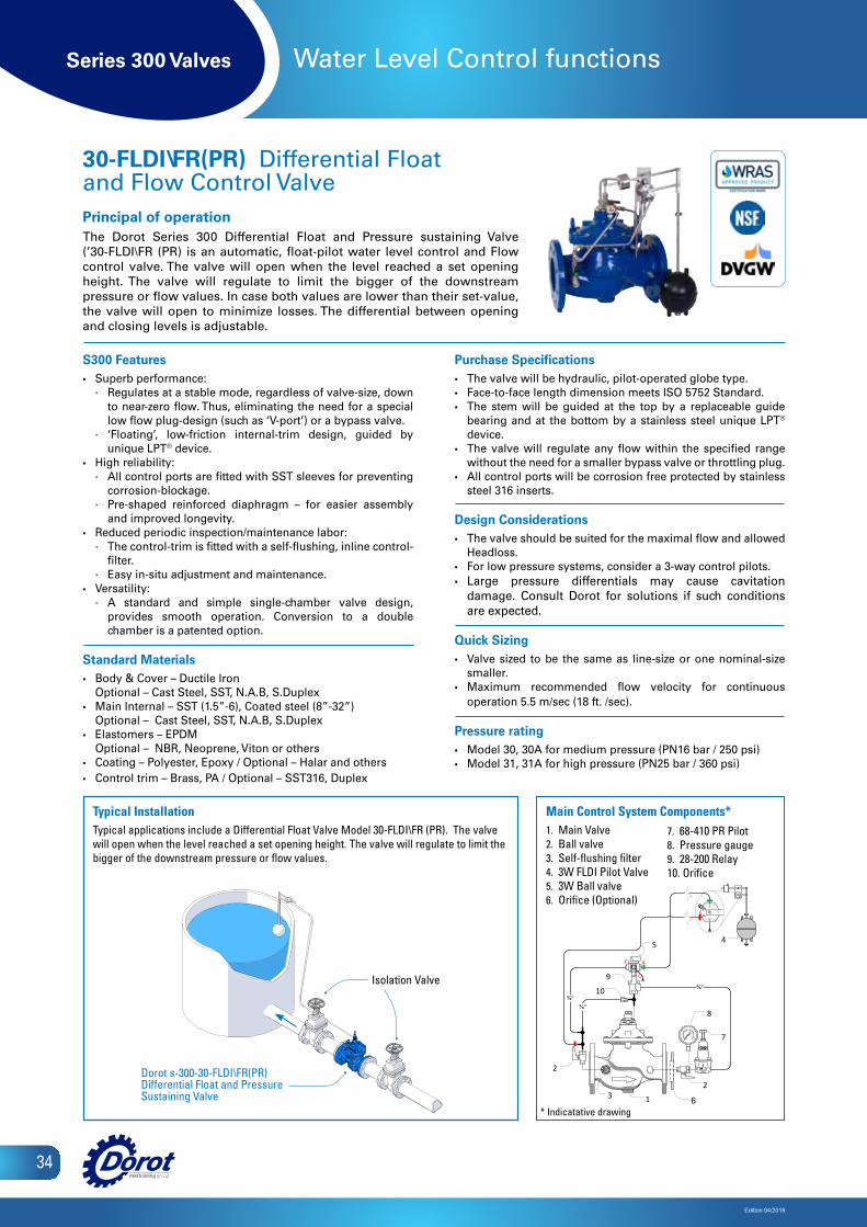
Series 300 Valves
Edition 04/2018
34
Water Level Control functions
S300 Features• Superb performance:
∙ Regulates at a stable mode, regardless of valve-size, down to near-zero flow. Thus, eliminating the need for a special low flow plug-design (such as ‘V-port’) or a bypass valve.
∙ ‘Floating’, low-friction internal-trim design, guided by unique LPT® device.
• High reliability: ∙ All control ports are fitted with SST sleeves for preventing
corrosion-blockage. ∙ Pre-shaped reinforced diaphragm – for easier assembly
and improved longevity.• Reduced periodic inspection/maintenance labor:
∙ The control-trim is fitted with a self-flushing, inline control-filter.
∙ Easy in-situ adjustment and maintenance. • Versatility:
∙ A standard and simple single-chamber valve design, provides smooth operation. Conversion to a double chamber is a patented option.
Standard Materials• Body & Cover – Ductile Iron
Optional – Cast Steel, SST, N.A.B, S.Duplex• Main Internal – SST (1.5”-6), Coated steel (8”-32”)
Optional – Cast Steel, SST, N.A.B, S.Duplex• Elastomers – EPDM
Optional – NBR, Neoprene, Viton or others• Coating – Polyester, Epoxy / Optional – Halar and others• Control trim – Brass, PA / Optional – SST316, Duplex
Purchase Specifications• The valve will be hydraulic, pilot-operated globe type.• Face-to-face length dimension meets ISO 5752 Standard. • The stem will be guided at the top by a replaceable guide
bearing and at the bottom by a stainless steel unique LPT® device.
• The valve will regulate any flow within the specified range without the need for a smaller bypass valve or throttling plug.
• All control ports will be corrosion free protected by stainless steel 316 inserts.
Design Considerations• The valve should be suited for the maximal flow and allowed
Headloss.• For low pressure systems, consider a 3-way control pilots.• Large pressure differentials may cause cavitation
damage. Consult Dorot for solutions if such conditions are expected.
Quick Sizing• Valve sized to be the same as line-size or one nominal-size
smaller.• Maximum recommended flow velocity for continuous
operation 5.5 m/sec (18 ft. /sec).
Pressure rating• Model 30, 30A for medium pressure (PN16 bar / 250 psi) • Model 31, 31A for high pressure (PN25 bar / 360 psi)
30-FLDI\FR(PR) Differential Float and Flow Control ValvePrincipal of operationThe Dorot Series 300 Differential Float and Pressure sustaining Valve (’30-FLDI\FR (PR) is an automatic, float-pilot water level control and Flow control valve. The valve will open when the level reached a set opening height. The valve will regulate to limit the bigger of the downstream pressure or flow values. In case both values are lower than their set-value, the valve will open to minimize losses. The differential between opening and closing levels is adjustable.
⅜"
AC
O
⅜"
⅜"
1
45
8
6
2
2
7
3
910
Main Control System Components*1. Main Valve2. Ball valve3. Self-flushing filter4. 3W FLDI Pilot Valve5. 3W Ball valve6. Orifice (Optional)
Isolation Valve
Dorot s-300-30-FLDI\FR(PR)Differential Float and Pressure Sustaining Valve
* Indicatative drawing
Typical InstallationTypical applications include a Differential Float Valve Model 30-FLDI\FR (PR). The valve will open when the level reached a set opening height. The valve will regulate to limit the bigger of the downstream pressure or flow values.
7. 68-410 PR Pilot8. Pressure gauge9. 28-200 Relay10. Orifice
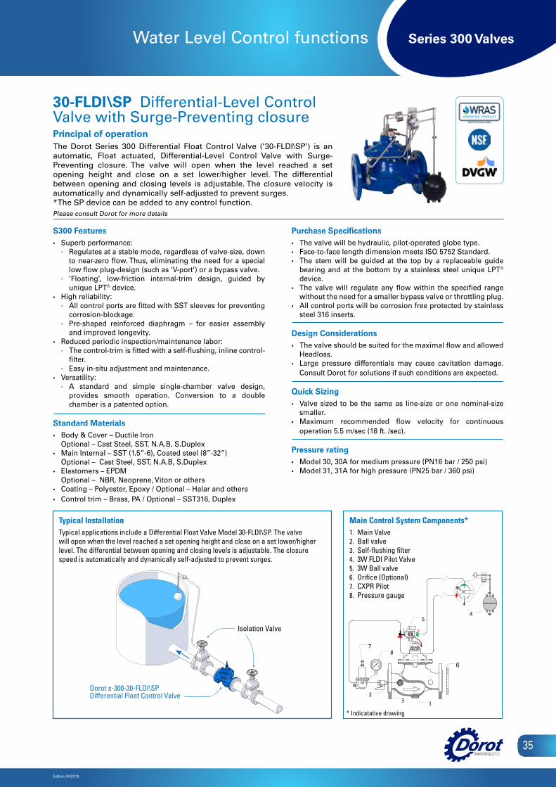
Series 300 Valves
Edition 04/2018
35
Water Level Control functions
S300 Features• Superb performance:
∙ Regulates at a stable mode, regardless of valve-size, down to near-zero flow. Thus, eliminating the need for a special low flow plug-design (such as ‘V-port’) or a bypass valve.
∙ ‘Floating’, low-friction internal-trim design, guided by unique LPT® device.
• High reliability: ∙ All control ports are fitted with SST sleeves for preventing
corrosion-blockage. ∙ Pre-shaped reinforced diaphragm – for easier assembly
and improved longevity.• Reduced periodic inspection/maintenance labor:
∙ The control-trim is fitted with a self-flushing, inline control-filter.
∙ Easy in-situ adjustment and maintenance. • Versatility:
∙ A standard and simple single-chamber valve design, provides smooth operation. Conversion to a double chamber is a patented option.
Standard Materials• Body & Cover – Ductile Iron
Optional – Cast Steel, SST, N.A.B, S.Duplex• Main Internal – SST (1.5”-6), Coated steel (8”-32”)
Optional – Cast Steel, SST, N.A.B, S.Duplex• Elastomers – EPDM
Optional – NBR, Neoprene, Viton or others• Coating – Polyester, Epoxy / Optional – Halar and others• Control trim – Brass, PA / Optional – SST316, Duplex
Purchase Specifications• The valve will be hydraulic, pilot-operated globe type. • Face-to-face length dimension meets ISO 5752 Standard.• The stem will be guided at the top by a replaceable guide
bearing and at the bottom by a stainless steel unique LPT®
device.• The valve will regulate any flow within the specified range
without the need for a smaller bypass valve or throttling plug.• All control ports will be corrosion free protected by stainless
steel 316 inserts.
Design Considerations• The valve should be suited for the maximal flow and allowed
Headloss.• Large pressure differentials may cause cavitation damage.
Consult Dorot for solutions if such conditions are expected.
Quick Sizing• Valve sized to be the same as line-size or one nominal-size
smaller.• Maximum recommended flow velocity for continuous
operation 5.5 m/sec (18 ft. /sec).
Pressure rating• Model 30, 30A for medium pressure (PN16 bar / 250 psi) • Model 31, 31A for high pressure (PN25 bar / 360 psi)
30-FLDI\ SP Differential-Level Control Valve with Surge-Preventing closurePrincipal of operationThe Dorot Series 300 Differential Float Control Valve (’30-FLDI\SP’) is an automatic, Float actuated, Differential-Level Control Valve with Surge-Preventing closure. The valve will open when the level reached a set opening height and close on a set lower/higher level. The differential between opening and closing levels is adjustable. The closure velocity is automatically and dynamically self-adjusted to prevent surges.*The SP device can be added to any control function. Please consult Dorot for more details
Main Control System Components1 Main Valve2 Ball valve 3 Self-flushing filter 4 3W FLDI Pilot Valve5 3W Ball valve6. Orifice (Optional)7. CXPR Pilot8. Pressure gauge
AC
O
OCI
4
132
8
5
6
7
Main Control System Components*1. Main Valve2. Ball valve3. Self-flushing filter4. 3W FLDI Pilot Valve5. 3W Ball valve6. Orifice (Optional)7. CXPR Pilot8. Pressure gauge
Isolation Valve
Dorot s-300-30-FLDI\SPDifferential Float Control Valve
Typical InstallationTypical applications include a Differential Float Valve Model 30-FLDI\SP. The valvewill open when the level reached a set opening height and close on a set lower/higherlevel. The differential between opening and closing levels is adjustable. The closurespeed is automatically and dynamically self-adjusted to prevent surges.
* Indicatative drawing
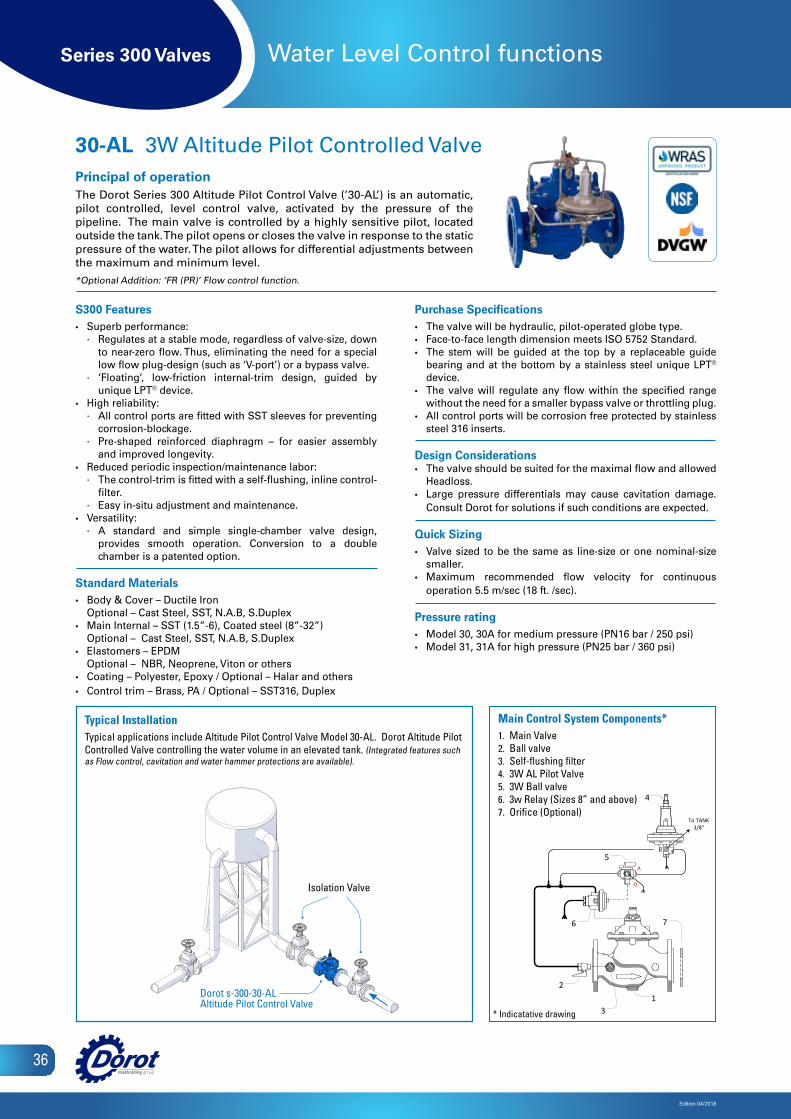
Series 300 Valves
Edition 04/2018
36
Water Level Control functions
S300 Features• Superb performance:
∙ Regulates at a stable mode, regardless of valve-size, down to near-zero flow. Thus, eliminating the need for a special low flow plug-design (such as ‘V-port’) or a bypass valve.
∙ ‘Floating’, low-friction internal-trim design, guided by unique LPT® device.
• High reliability: ∙ All control ports are fitted with SST sleeves for preventing
corrosion-blockage. ∙ Pre-shaped reinforced diaphragm – for easier assembly
and improved longevity.• Reduced periodic inspection/maintenance labor:
∙ The control-trim is fitted with a self-flushing, inline control-filter.
∙ Easy in-situ adjustment and maintenance. • Versatility:
∙ A standard and simple single-chamber valve design, provides smooth operation. Conversion to a double chamber is a patented option.
Standard Materials• Body & Cover – Ductile Iron
Optional – Cast Steel, SST, N.A.B, S.Duplex• Main Internal – SST (1.5”-6), Coated steel (8”-32”)
Optional – Cast Steel, SST, N.A.B, S.Duplex• Elastomers – EPDM
Optional – NBR, Neoprene, Viton or others• Coating – Polyester, Epoxy / Optional – Halar and others• Control trim – Brass, PA / Optional – SST316, Duplex
Purchase Specifications• The valve will be hydraulic, pilot-operated globe type. • Face-to-face length dimension meets ISO 5752 Standard.• The stem will be guided at the top by a replaceable guide
bearing and at the bottom by a stainless steel unique LPT® device.
• The valve will regulate any flow within the specified range without the need for a smaller bypass valve or throttling plug.
• All control ports will be corrosion free protected by stainless steel 316 inserts.
Design Considerations• The valve should be suited for the maximal flow and allowed
Headloss.• Large pressure differentials may cause cavitation damage.
Consult Dorot for solutions if such conditions are expected.
Quick Sizing• Valve sized to be the same as line-size or one nominal-size
smaller.• Maximum recommended flow velocity for continuous
operation 5.5 m/sec (18 ft. /sec).
Pressure rating• Model 30, 30A for medium pressure (PN16 bar / 250 psi) • Model 31, 31A for high pressure (PN25 bar / 360 psi)
30-AL 3W Altitude Pilot Controlled Valve Principal of operationThe Dorot Series 300 Altitude Pilot Control Valve (’30-AL’) is an automatic, pilot controlled, level control valve, activated by the pressure of the pipeline. The main valve is controlled by a highly sensitive pilot, located outside the tank. The pilot opens or closes the valve in response to the static pressure of the water. The pilot allows for differential adjustments between the maximum and minimum level.
*Optional Addition: ‘FR (PR)’ Flow control function.
Isolation Valve
Dorot s-300-30-ALAltitude Pilot Control Valve
1 Main Valve2 Ball valve 3 Self-flushing filter 4 3W AL Pilot Valve5 3W Ball valve
7
To TANK3/8"
AC
O
4
5
13
2
6
6 3w Relay (Sizes 8" and above)7 Orifice (Optional)
Main Control System Components*1. Main Valve2. Ball valve3. Self-flushing filter4. 3W AL Pilot Valve5. 3W Ball valve6. 3w Relay (Sizes 8” and above)7. Orifice (Optional)
* Indicatative drawing
Typical InstallationTypical applications include Altitude Pilot Control Valve Model 30-AL. Dorot Altitude Pilot Controlled Valve controlling the water volume in an elevated tank. (Integrated features such as Flow control, cavitation and water hammer protections are available).
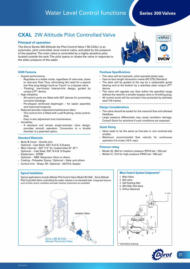
Series 300 Valves
Edition 04/2018
37
Water Level Control functions
S300 Features• Superb performance:
∙ Regulates at a stable mode, regardless of valve-size, down to near-zero flow. Thus, eliminating the need for a special low flow plug-design (such as ‘V-port’) or a bypass valve.
∙ ‘Floating’, low-friction internal-trim design, guided by unique LPT® device.
• High reliability: ∙ All control ports are fitted with SST sleeves for preventing
corrosion-blockage. ∙ Pre-shaped reinforced diaphragm – for easier assembly
and improved longevity.• Reduced periodic inspection/maintenance labor:
∙ The control-trim is fitted with a self-flushing, inline control-filter.
∙ Easy in-situ adjustment and maintenance. • Versatility:
∙ A standard and simple single-chamber valve design, provides smooth operation. Conversion to a double chamber is a patented option.
Standard Materials• Body & Cover – Ductile Iron
Optional – Cast Steel, SST, N.A.B, S.Duplex• Main Internal – SST (1.5”-6), Coated steel (8”-32”)
Optional – Cast Steel, SST, N.A.B, S.Duplex• Elastomers – EPDM
Optional – NBR, Neoprene, Viton or others• Coating – Polyester, Epoxy / Optional – Halar and others• Control trim – Brass, PA / Optional – SST316, Duplex
Purchase Specifications• The valve will be hydraulic, pilot-operated globe type. • Face-to-face length dimension meets ISO 5752 Standard.• The stem will be guided at the top by a replaceable guide
bearing and at the bottom by a stainless steel unique LPT®
device.• The valve will regulate any flow within the specified range
without the need for a smaller bypass valve or throttling plug.• All control ports will be corrosion free protected by stainless
steel 316 inserts.
Design Considerations• The valve should be suited for the maximal flow and allowed
Headloss.• Large pressure differentials may cause cavitation damage.
Consult Dorot for solutions if such conditions are expected.
Quick Sizing• Valve sized to be the same as line-size or one nominal-size
smaller.• Maximum recommended flow velocity for continuous
operation 5.5 m/sec (18 ft. /sec).
Pressure rating• Model 30, 30A for medium pressure (PN16 bar / 250 psi) • Model 31, 31A for high pressure (PN25 bar / 360 psi)
CXAL 2W Altitude Pilot Controlled ValvePrincipal of operationThe Dorot Series 300 Altitude 2w Pilot Control Valve (’30-CXAL) is anautomatic, pilot controlled, level control valve, activated by the pressureof the pipeline. The main valve is controlled by a highly sensitive pilot,located outside the tank. The pilot opens or closes the valve in response tothe static pressure of the water.
Typical InstallationTypical applications include Altitude Pilot Control Valve Model 30-CXAL. Dorot Altitude Pilot Controlled Valve controlling the water volume in an elevated tank. (Integrated features such as Flow control, cavitation and water hammer protections are available).
Isolation Valve
Dorot s-300-30-CXALAltitude Pilot Control Valve
To TANK
1 Main Valve2 Ball valve 3 Self-flushing filter 4 2W CXAL Pilot Valve5 Orifice (Optional)
Main Control System Components
13
2
2
4
5
2
Main Control System Components*1. Main Valve2. Ball valve3. Self-flushing filter4. 2W CXAL Pilot Valve5. Orifice (Optional)
* Indicatative drawing

Series 300 Valves
Edition 04/2018
38
Pump Control functions
S300 Features• Superb performance:
∙ Regulates at a stable mode, regardless of valve-size, down to near-zero flow. Thus, eliminating the need for a special low flow plug-design (such as ‘V-port’) or a bypass valve.
∙ ‘Floating’, low-friction internal-trim design, guided by unique LPT® device.
• High reliability: ∙ All control ports are fitted with SST sleeves for preventing
corrosion-blockage. ∙ Pre-shaped reinforced diaphragm – for easier assembly
and improved longevity.• Reduced periodic inspection/maintenance labor:
∙ The control-trim is fitted with a self-flushing, inline control-filter.
∙ Easy in-situ adjustment and maintenance. • Versatility:
∙ A standard and simple single-chamber valve design, provides smooth operation. Conversion to a double chamber is a patented option.
Standard Materials• Body & Cover – Ductile Iron
Optional – Cast Steel, SST, N.A.B, S.Duplex• Main Internal – SST (1.5”-6), Coated steel (8”-32”)
Optional – Cast Steel, SST, N.A.B, S.Duplex• Elastomers – EPDM
Optional – NBR, Neoprene, Viton or others• Coating – Polyester, Epoxy / Optional – Halar and others• Control trim – Brass, PA / Optional – SST316, Duplex
Purchase Specifications• The valve will be hydraulic, pilot-operated globe type. • Face-to-face length dimension meets ISO 5752 Standard.• The stem will be guided at the top by a replaceable guide
bearing and at the bottom by a stainless steel unique LPT® device.
• The valve will regulate any flow within the specified range without the need for a smaller bypass valve or throttling plug.
• All control ports will be corrosion free protected by stainless steel 316 inserts.
Design Considerations• The valve should be suited for the maximal flow and allowed
Headloss.• Large pressure differentials may cause cavitation damage.
Consult Dorot for solutions if such conditions are expected.
Quick Sizing• Valve sized to be the same as line-size or one nominal-size
smaller.• Maximum recommended flow velocity for continuous
operation 5.5 m/sec (18 ft. /sec).
Pressure rating• Model 30, 30A for medium pressure (PN16 bar / 250 psi) • Model 31, 31A for high pressure (PN25 bar / 360 psi)
30-BC Pump Control ValvePrincipal of operationThe Dorot Series 300 Pump Control Valve (’30-BC’) is an automatic controlled valve, activated by the pressure of the pipeline. The valve will minimize pump starting and stopping surges by slowly opening at pump startup and slowly closing prior to pump shutdown. The valve will close instantly on power failure.
Dorot DAV-MAir Valve
Dorot DAV-M Air ValveDorot DAV-M Air Valve
Isolation Valve
Isolation Valve
Dorot s-300-30-BCPump Control Valve
Dorot s-300-30-BCPump Control Valve
Main Control System Components
1
4
2
1. 3/2 hyd. relay-valve model 66-2102. 3/2, N.C Solenoid valve 3. 3/2 hyd. relay-valve model 282004. isolation ball-valve 5. Limit switch assembly6. ‘Y’ pattern control-filter7. Check valve
8. Needle Valve
3
4
56
7
7
78
Main Control System Components*1. 3/2 hyd. relay-valve model 66-2102. 3/2, N.C Solenoid valve3. 3/2 hyd. relay-valve model 28-3004. Isolation ball-valve5. Limit switch assembly6. ‘Y’ pattern control-filter7. Check valve8. Needle Valve
Isolation Valve
Isolation Valve
* Indicatative drawing
Typical InstallationTypical applications include a Pump Control Valve Model 30-BC. The valve is assembled downstream of a pump and will open and close slowly when the solenoid is energized\de-energized respectively.

Series 300 Valves
Edition 04/2018
39
Pump Control functions
S300 Features• Superb performance:
∙ Regulates at a stable mode, regardless of valve-size, down to near-zero flow. Thus, eliminating the need for a special low flow plug-design (such as ‘V-port’) or a bypass valve.
∙ ‘Floating’, low-friction internal-trim design, guided by unique LPT® device.
• High reliability: ∙ All control ports are fitted with SST sleeves for preventing
corrosion-blockage. ∙ Pre-shaped reinforced diaphragm – for easier assembly
and improved longevity.• Reduced periodic inspection/maintenance labor:
∙ The control-trim is fitted with a self-flushing, inline control-filter.
∙ Easy in-situ adjustment and maintenance. • Versatility:
∙ A standard and simple single-chamber valve design, provides smooth operation. Conversion to a double chamber is a patented option.
Standard Materials• Body & Cover – Ductile Iron
Optional – Cast Steel, SST, N.A.B, S.Duplex• Main Internal – SST (1.5”-6), Coated steel (8”-32”)
Optional – Cast Steel, SST, N.A.B, S.Duplex• Elastomers – EPDM
Optional – NBR, Neoprene, Viton or others• Coating – Polyester, Epoxy / Optional – Halar and others• Control trim – Brass, PA / Optional – SST316, Duplex
Purchase Specifications• The valve will be hydraulic, pilot-operated globe type. • Face-to-face length dimension meets ISO 5752 Standard.• The stem will be guided at the top by a replaceable guide
bearing and at the bottom by a stainless steel unique LPT®
device.• The valve will regulate any flow within the specified range
without the need for a smaller bypass valve or throttling plug.• All control ports will be corrosion free protected by stainless
steel 316 inserts.
Design Considerations• The valve should be suited for the maximal flow and allowed
Headloss.• Large pressure differentials may cause cavitation damage.
Consult Dorot for solutions if such conditions are expected.
Quick Sizing• Valve sized to be the same as line-size or one nominal-size
smaller.• Maximum recommended flow velocity for continuous
operation 5.5 m/sec (18 ft. /sec).
Pressure rating• Model 30, 30A for medium pressure (PN16 bar / 250 psi) • Model 31, 31A for high pressure (PN25 bar / 360 psi)
30-BC\ PS Pump Control and Pressure Sustaining ValvePrincipal of operationThe Dorot Series 300 Pump Control and Pressure Sustaining Valve (’30-BC\PS’) is an automatic controlled valve, activated by the pressure of the pipeline. The valve willminimize pump starting and stopping surges by slowly opening at pumpstartup and slowly closing prior to pump shutdown. The valve will maintainpre-set upstream pressure, limiting flow velocity at line filling stages.
Main Control System Components1. Pilot valve model 31-10S2. 3/2, N.C Solenoid valve 3. 3/2 hyd. relay-valve model 282004. isolation ball-valve 5. Limit switch assembly
6. Self flushing control-filter7. Check valve8. Needle Valve9. Pressure gauge
44
7
6 6
95
7
8
21
3
Main Control System Components*1. Pilot valve model 31-10S2. 3/2, N.C&N.C Solenoid valves3. 3/2 hyd. relay-valve model 28-2004. Isolation ball-valve5. Limit switch assembly6. Self flushing control-filter7. Check valve8. Needle Valve9. Pressure gauge
Typical InstallationThe Dorot Series 300 Pump Control and Pressure Sustaining Valve (’30-BC\PS’) will minimize pump starting and stopping surges by slowly opening at pump startup and slowly closing prior to pump shutdown.
Dorot DAV-MAir Valve
Dorot DAV-M Air ValveDorot DAV-M Air Valve
Isolation Valve
Isolation Valve
Dorot s-300-30-BC\PSPump Control Valve
Dorot s-300-30-BC\PSPump Control Valve
Isolation Valve
Isolation Valve
* Indicatative drawing
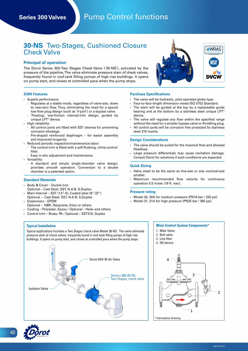
Series 300 Valves
Edition 04/2018
40
Pump Control functions
S300 Features• Superb performance:
∙ Regulates at a stable mode, regardless of valve-size, down to near-zero flow. Thus, eliminating the need for a special low flow plug-design (such as ‘V-port’) or a bypass valve.
∙ ‘Floating’, low-friction internal-trim design, guided by unique LPT® device.
• High reliability: ∙ All control ports are fitted with SST sleeves for preventing
corrosion-blockage. ∙ Pre-shaped reinforced diaphragm – for easier assembly
and improved longevity.• Reduced periodic inspection/maintenance labor:
∙ The control-trim is fitted with a self-flushing, inline control-filter.
∙ Easy in-situ adjustment and maintenance. • Versatility:
∙ A standard and simple single-chamber valve design, provides smooth operation. Conversion to a double chamber is a patented option.
Standard Materials• Body & Cover – Ductile Iron
Optional – Cast Steel, SST, N.A.B, S.Duplex• Main Internal – SST (1.5”-6), Coated steel (8”-32”)
Optional – Cast Steel, SST, N.A.B, S.Duplex• Elastomers – EPDM
Optional – NBR, Neoprene, Viton or others• Coating – Polyester, Epoxy / Optional – Halar and others• Control trim – Brass, PA / Optional – SST316, Duplex
Purchase Specifications• The valve will be hydraulic, pilot-operated globe type. • Face-to-face length dimension meets ISO 5752 Standard.• The stem will be guided at the top by a replaceable guide
bearing and at the bottom by a stainless steel unique LPT® device.
• The valve will regulate any flow within the specified range without the need for a smaller bypass valve or throttling plug.
• All control ports will be corrosion free protected by stainless steel 316 inserts.
Design Considerations• The valve should be suited for the maximal flow and allowed
Headloss.• Large pressure differentials may cause cavitation damage.
Consult Dorot for solutions if such conditions are expected.
Quick Sizing• Valve sized to be the same as line-size or one nominal-size
smaller.• Maximum recommended flow velocity for continuous
operation 5.5 m/sec (18 ft. /sec).
Pressure rating• Model 30, 30A for medium pressure (PN16 bar / 250 psi) • Model 31, 31A for high pressure (PN25 bar / 360 psi)
30-NS Two-Stages, Cushioned Closure Check ValvePrincipal of operationThe Dorot Series 300 Two Stages Check Valve (’30-NS’), activated by the pressure of the pipeline, The valve eliminate pressure slam of check valves, frequently found in roof-tank filling pumps of high-rise buildings. It opens on pump start, and closes at controlled pace when the pump stops.
Main Control System Components1 Main Valve2 Ball valve 3 Line filter 4 NS device
4
3
1
2
Main Control System Components*1. Main Valve2. Ball valve3. Line filter4. NS device
Dorot DAV-M Air Valve
Dorot s-300-30-NSTwo-Stages, check valve
Isolation Valve
* Indicatative drawing
Typical InstallationTypical applications Includes a Two Stages check valve Model 30-NS. The valve eliminate pressure slam of check valves, frequently found in roof-tank filling pumps of high-rise buildings. It opens on pump start, and closes at controlled pace when the pump stops.
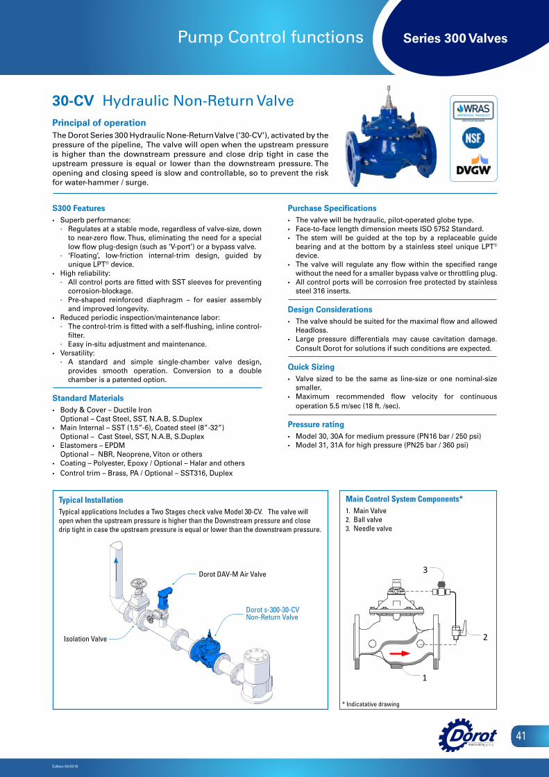
Series 300 Valves
Edition 04/2018
41
Pump Control functions
S300 Features• Superb performance:
∙ Regulates at a stable mode, regardless of valve-size, down to near-zero flow. Thus, eliminating the need for a special low flow plug-design (such as ‘V-port’) or a bypass valve.
∙ ‘Floating’, low-friction internal-trim design, guided by unique LPT® device.
• High reliability: ∙ All control ports are fitted with SST sleeves for preventing
corrosion-blockage. ∙ Pre-shaped reinforced diaphragm – for easier assembly
and improved longevity.• Reduced periodic inspection/maintenance labor:
∙ The control-trim is fitted with a self-flushing, inline control-filter.
∙ Easy in-situ adjustment and maintenance. • Versatility:
∙ A standard and simple single-chamber valve design, provides smooth operation. Conversion to a double chamber is a patented option.
Standard Materials• Body & Cover – Ductile Iron
Optional – Cast Steel, SST, N.A.B, S.Duplex• Main Internal – SST (1.5”-6), Coated steel (8”-32”)
Optional – Cast Steel, SST, N.A.B, S.Duplex• Elastomers – EPDM
Optional – NBR, Neoprene, Viton or others• Coating – Polyester, Epoxy / Optional – Halar and others• Control trim – Brass, PA / Optional – SST316, Duplex
Purchase Specifications• The valve will be hydraulic, pilot-operated globe type. • Face-to-face length dimension meets ISO 5752 Standard.• The stem will be guided at the top by a replaceable guide
bearing and at the bottom by a stainless steel unique LPT®
device.• The valve will regulate any flow within the specified range
without the need for a smaller bypass valve or throttling plug.• All control ports will be corrosion free protected by stainless
steel 316 inserts.
Design Considerations• The valve should be suited for the maximal flow and allowed
Headloss.• Large pressure differentials may cause cavitation damage.
Consult Dorot for solutions if such conditions are expected.
Quick Sizing• Valve sized to be the same as line-size or one nominal-size
smaller.• Maximum recommended flow velocity for continuous
operation 5.5 m/sec (18 ft. /sec).
Pressure rating• Model 30, 30A for medium pressure (PN16 bar / 250 psi) • Model 31, 31A for high pressure (PN25 bar / 360 psi)
30-CV Hydraulic Non-Return ValvePrincipal of operationThe Dorot Series 300 Hydraulic None-Return Valve (’30-CV’), activated by the pressure of the pipeline, The valve will open when the upstream pressure is higher than the downstream pressure and close drip tight in case the upstream pressure is equal or lower than the downstream pressure. The opening and closing speed is slow and controllable, so to prevent the risk for water-hammer / surge.
Main Control System Components*1. Main Valve2. Ball valve3. Needle valve
Typical InstallationTypical applications Includes a Two Stages check valve Model 30-CV. The valve will open when the upstream pressure is higher than the Downstream pressure and close drip tight in case the upstream pressure is equal or lower than the downstream pressure.
Main Control System Components1 Main Valve2 Ball valve 3 Needle valve
3
1
2
Dorot DAV-M Air Valve
Dorot s-300-30-CVNon-Return Valve
Isolation Valve
* Indicatative drawing

Series 300 Valves
Edition 04/2018
42
Pump Control functions
S300 Features• Superb performance:
∙ Regulates at a stable mode, regardless of valve-size, down to near-zero flow. Thus, eliminating the need for a special low flow plug-design (such as ‘V-port’) or a bypass valve.
∙ ‘Floating’, low-friction internal-trim design, guided by unique LPT® device.
• High reliability: ∙ All control ports are fitted with SST sleeves for preventing
corrosion-blockage. ∙ Pre-shaped reinforced diaphragm – for easier assembly
and improved longevity.• Reduced periodic inspection/maintenance labor:
∙ The control-trim is fitted with a self-flushing, inline control-filter.
∙ Easy in-situ adjustment and maintenance. • Versatility:
∙ A standard and simple single-chamber valve design, provides smooth operation. Conversion to a double chamber is a patented option.
Standard Materials• Body & Cover – Ductile Iron
Optional – Cast Steel, SST, N.A.B, S.Duplex• Main Internal – SST (1.5”-6), Coated steel (8”-32”)
Optional – Cast Steel, SST, N.A.B, S.Duplex• Elastomers – EPDM
Optional – NBR, Neoprene, Viton or others• Coating – Polyester, Epoxy / Optional – Halar and others• Control trim – Brass, PA / Optional – SST316, Duplex
Purchase Specifications• The valve will be hydraulic, pilot-operated globe type. • Face-to-face length dimension meets ISO 5752 Standard.• The stem will be guided at the top by a replaceable guide
bearing and at the bottom by a stainless steel unique LPT® device.
• The valve will regulate any flow within the specified range without the need for a smaller bypass valve or throttling plug.
• All control ports will be corrosion free protected by stainless steel 316 inserts.
Design Considerations• The valve should be suited for the maximal flow and allowed
Headloss.• Large pressure differentials may cause cavitation damage.
Consult Dorot for solutions if such conditions are expected.
Quick Sizing• The valve should be sized to match the well flow at 5 mwc/8
psi in the valve site (pump head water table depth): D[mm] ≥ 170 x √Flow [m3/hr] D[inch] ≥ 0.55 x √Flow [gpm]
Pressure rating• Model 30, 30A for medium pressure (PN16 bar / 250 psi) • Model 31, 31A for high pressure (PN25 bar / 360 psi)
30-DW Deep Well (Borehole) Pump Control ValvePrincipal of operationThe Dorot Series 300 Deep Well Pump Control Valve (’30-DW’) is an automatic controlled valve, activated by the pressure of the pipeline. When the pump starts, the valve slowly closes, gradually increasing network pressure. Before pump shut-off, the valve slowly opens, gradually reducing network pressure.
Isolation Valve
Isolation Valve
Dorot s-300-30-DWDeep Well Pump
Control Valve
21 2 1
4
7
7
22
1 3
5
3
6
Main Control System Components*1. S300 valve2. 3/2, N.O& N.C Solenoid valves3. Self-Flushing, inline control-filter4. Isolation ball-valve5. Limit switch assembly6. Check valve7. Needle valveDorot DAV-M
Air Valve
Dorot Check-Valve
Dorot DAV-M Air Valve
* Indicatative drawing
Typical InstallationTypical applications include a Pump Control Valve Model 30-DW. The valve eliminates surges caused by the start-up and shut-off of vertical or submersible pumps. It is a relief valve, assembled on a T-junction of the main pipeline

Series 300 Valves
Edition 04/2018
43
Safety functions
S300 Features• Superb performance:
∙ Regulates at a stable mode, regardless of valve-size, down to near-zero flow. Thus, eliminating the need for a special low flow plug-design (such as ‘V-port’) or a bypass valve.
∙ ‘Floating’, low-friction internal-trim design, guided by unique LPT® device.
• High reliability: ∙ All control ports are fitted with SST sleeves for preventing
corrosion-blockage. ∙ Pre-shaped reinforced diaphragm – for easier assembly
and improved longevity.• Reduced periodic inspection/maintenance labor:
∙ The control-trim is fitted with a self-flushing, inline control-filter.
∙ Easy in-situ adjustment and maintenance. • Versatility:
∙ A standard and simple single-chamber valve design, provides smooth operation. Conversion to a double chamber is a patented option.
Standard Materials• Body & Cover – Ductile Iron
Optional – Cast Steel, SST, N.A.B, S.Duplex• Main Internal – SST (1.5”-6), Coated steel (8”-32”)
Optional – Cast Steel, SST, N.A.B, S.Duplex• Elastomers – EPDM
Optional – NBR, Neoprene, Viton or others• Coating – Polyester, Epoxy / Optional – Halar and others• Control trim – Brass, PA / Optional – SST316, Duplex
Purchase Specifications• The valve will be hydraulic, pilot-operated globe type. • Face-to-face length dimension meets ISO 5752 Standard.• The stem will be guided at the top by a replaceable guide
bearing and at the bottom by a stainless steel unique LPT® device.
• The valve will regulate any flow within the specified range without the need for a smaller bypass valve or throttling plug.
• All control ports will be corrosion free protected by stainless steel 316 inserts.
Design Considerations• The valve should be suited for the maximal flow.• Install a manual separation/throttling valve, upstream of the
valve position.• The valve sensor tube must be connected to the main line.
Quick Sizing• The valve should be sized to match the 80% of the normal
flow at static head in the valve site: D[mm] ≥ √(250 x Flow[m3/hr] / √Pressure[mwc]) D[inch] ≥ √(0.109 x Flow[gpm] / √Pressure[psi])
Pressure rating• Model 30, 30A for medium pressure (PN16 bar / 250 psi) • Model 31, 31A for high pressure (PN25 bar / 360 psi)
30-RE Surge Anticipating ValvePrincipal of operationThe Dorot Series 300 Surge Anticipating Valve (’30-RE’) is an automatic controlled valve, activated by the pressure of the pipeline. The valve protects the pumping system from water hammer, caused by sudden pump shut-off (case of power failure, for example). The valve is assembled on a T-junction of the main pipeline, instantly opens when the pump stops, relieving the returning high pressure wave. The valve slowly closes once the pressure returns to the static level. The valve also functions as a pressure relief valve.
Isolation Valve
Dorot s-300-30-BCPump Control Valve
Main Header
2
1
3
22
47
5
6
8 9
Main Control System Components1 Main Valve2 Ball valve 3 Filter 4 2W Pilot Valve5 3W Pilot Valve6 Fast Acting Relay7 Pressure Gauge8 Needle Valve9 Check Valve
Main Control System Components*1. Main Valve2. Ball valve3. Filter4. 2W Pilot Valve5. 3W Pilot Valve
6. Fast Acting Relay7. Pressure Gauge8. Needle Valve9. Check Valve
Dorot DAV-M Air Valve
Dorot DAV-M Air Valve
Dorot s-300-30-RESurge Anticipating Valve
* Indicatative drawing
Typical InstallationTypical applications include Pressure Sustaining Valve Model 30-RE.The Dorot Surge Anticipating Valve prevents water-hammer surges caused by an un-expected pump shut-off.
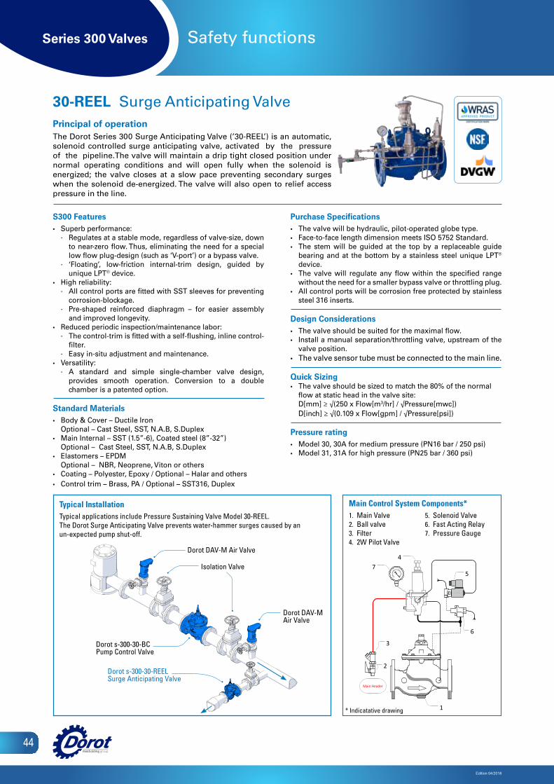
Series 300 Valves
Edition 04/2018
44
Safety functions
S300 Features• Superb performance:
∙ Regulates at a stable mode, regardless of valve-size, down to near-zero flow. Thus, eliminating the need for a special low flow plug-design (such as ‘V-port’) or a bypass valve.
∙ ‘Floating’, low-friction internal-trim design, guided by unique LPT® device.
• High reliability: ∙ All control ports are fitted with SST sleeves for preventing
corrosion-blockage. ∙ Pre-shaped reinforced diaphragm – for easier assembly
and improved longevity.• Reduced periodic inspection/maintenance labor:
∙ The control-trim is fitted with a self-flushing, inline control-filter.
∙ Easy in-situ adjustment and maintenance. • Versatility:
∙ A standard and simple single-chamber valve design, provides smooth operation. Conversion to a double chamber is a patented option.
Standard Materials• Body & Cover – Ductile Iron
Optional – Cast Steel, SST, N.A.B, S.Duplex• Main Internal – SST (1.5”-6), Coated steel (8”-32”)
Optional – Cast Steel, SST, N.A.B, S.Duplex• Elastomers – EPDM
Optional – NBR, Neoprene, Viton or others• Coating – Polyester, Epoxy / Optional – Halar and others• Control trim – Brass, PA / Optional – SST316, Duplex
Purchase Specifications• The valve will be hydraulic, pilot-operated globe type. • Face-to-face length dimension meets ISO 5752 Standard.• The stem will be guided at the top by a replaceable guide
bearing and at the bottom by a stainless steel unique LPT® device.
• The valve will regulate any flow within the specified range without the need for a smaller bypass valve or throttling plug.
• All control ports will be corrosion free protected by stainless steel 316 inserts.
Design Considerations• The valve should be suited for the maximal flow.• Install a manual separation/throttling valve, upstream of the
valve position.• The valve sensor tube must be connected to the main line.
Quick Sizing• The valve should be sized to match the 80% of the normal
flow at static head in the valve site: D[mm] ≥ √(250 x Flow[m3/hr] / √Pressure[mwc]) D[inch] ≥ √(0.109 x Flow[gpm] / √Pressure[psi])
Pressure rating• Model 30, 30A for medium pressure (PN16 bar / 250 psi) • Model 31, 31A for high pressure (PN25 bar / 360 psi)
30-REEL Surge Anticipating ValvePrincipal of operationThe Dorot Series 300 Surge Anticipating Valve (’30-REEL’) is an automatic, solenoid controlled surge anticipating valve, activated by the pressure of the pipeline.The valve will maintain a drip tight closed position under normal operating conditions and will open fully when the solenoid is energized; the valve closes at a slow pace preventing secondary surges when the solenoid de-energized. The valve will also open to relief access pressure in the line.
Isolation Valve
Dorot s-300-30-BCPump Control Valve
2
6
Main Header
3
1
5
47
Main Control System Components1 Main Valve2 Ball valve 3 Filter 4 2W Pilot Valve5 Solenoid Valve6 Fast Acting Relay7 Pressure Gauge
Main Control System Components*1. Main Valve2. Ball valve3. Filter4. 2W Pilot Valve
Dorot DAV-M Air Valve
Dorot DAV-M Air Valve
Dorot s-300-30-REELSurge Anticipating Valve
Typical InstallationTypical applications include Pressure Sustaining Valve Model 30-REEL.The Dorot Surge Anticipating Valve prevents water-hammer surges caused by an un-expected pump shut-off.
5. Solenoid Valve6. Fast Acting Relay7. Pressure Gauge
* Indicatative drawing

Series 300 Valves
Edition 04/2018
45
Safety functions
S300 Features• Superb performance:
∙ Regulates at a stable mode, regardless of valve-size, down to near-zero flow. Thus, eliminating the need for a special low flow plug-design (such as ‘V-port’) or a bypass valve.
∙ ‘Floating’, low-friction internal-trim design, guided by unique LPT® device.
• High reliability: ∙ All control ports are fitted with SST sleeves for preventing
corrosion-blockage. ∙ Pre-shaped reinforced diaphragm – for easier assembly
and improved longevity.• Reduced periodic inspection/maintenance labor:
∙ The control-trim is fitted with a self-flushing, inline control-filter.
∙ Easy in-situ adjustment and maintenance. • Versatility:
∙ A standard and simple single-chamber valve design, provides smooth operation. Conversion to a double chamber is a patented option.
Standard Materials• Body & Cover – Ductile Iron
Optional – Cast Steel, SST, N.A.B, S.Duplex• Main Internal – SST (1.5”-6), Coated steel (8”-32”)
Optional – Cast Steel, SST, N.A.B, S.Duplex• Elastomers – EPDM
Optional – NBR, Neoprene, Viton or others• Coating – Polyester, Epoxy / Optional – Halar and others• Control trim – Brass, PA / Optional – SST316, Duplex
Purchase Specifications• The valve will be hydraulic, pilot-operated globe type. • Face-to-face length dimension meets ISO 5752 Standard.• The stem will be guided at the top by a replaceable guide
bearing and at the bottom by a stainless steel unique LPT® device.
• The valve will regulate any flow within the specified range without the need for a smaller bypass valve or throttling plug.
• All control ports will be corrosion free protected by stainless steel 316 inserts.
Design Considerations• The valve should be suited for the maximal flow and allowed
Headloss.• Large pressure differentials may cause cavitation damage.
Consult Dorot for solutions if such conditions are expected.
Quick Sizing• The valve should be sized to match the expected relief flow
at the set opening pressure: D[mm] ≥ √(250 x Flow[m3/hr.] / √Pressure[mwc]) D[inch] ≥ √(0.109 x Flow[gpm] / √Pressure[psi])
Pressure rating• Model 30, 30A for medium pressure (PN16 bar / 250 psi) • Model 31, 31A for high pressure (PN25 bar / 360 psi)
30-QR Quick Pressure-Relief ValvePrincipal of operationThe Dorot Series 300 Quick Relief Valve (’30-QR’) activates by the pressure of the pipeline. The valve opens instantly when the pressure in the pipeline exceeds the safe level, thus relieving excessive pressure from the network.When the pressure returns to normal, the valve closes slowly, at an adjustable pace.
Main Control System Components1 Main Valve2 Ball valve 3 Self-flushing filter 4 2W PS Pilot Valve5 Pressure Gauge
2
54
2
2
3 1
⅜"
Main Control System Components*1. Main Valve2. Ball valve3. Self-flushing filter4. 2W PS Pilot Valve5. Pressure Gauge
Strainer
Isolation ValveIsolation
Valve
Dorot s-300-30-PRM[HyMod]Pressure Reducing Valve
Dorot s-300-30-QRPressure Relief Valve
Dorot DAV-M Air Valve
Isolation Valve
* Indicatative drawing
Typical InstallationTypical applications include Pressure Sustaining Valve Model 30-QR. The Dorot Quick Pressure-relief Valve protects a system against pressure surges caused by pump start-up or valves closure.

Series 300 Valves
Edition 04/2018
46
Safety functions
S300 Features• Superb performance:
∙ Regulates at a stable mode, regardless of valve-size, down to near-zero flow. Thus, eliminating the need for a special low flow plug-design (such as ‘V-port’) or a bypass valve.
∙ ‘Floating’, low-friction internal-trim design, guided by unique LPT® device.
• High reliability: ∙ All control ports are fitted with SST sleeves for preventing
corrosion-blockage. ∙ Pre-shaped reinforced diaphragm – for easier assembly
and improved longevity.• Reduced periodic inspection/maintenance labor:
∙ The control-trim is fitted with a self-flushing, inline control-filter.
∙ Easy in-situ adjustment and maintenance. • Versatility:
∙ A standard and simple single-chamber valve design, provides smooth operation. Conversion to a double chamber is a patented option.
Standard Materials• Body & Cover – Ductile Iron
Optional – Cast Steel, SST, N.A.B, S.Duplex• Main Internal – SST (1.5”-6), Coated steel (8”-32”)
Optional – Cast Steel, SST, N.A.B, S.Duplex• Elastomers – EPDM
Optional – NBR, Neoprene, Viton or others• Coating – Polyester, Epoxy / Optional – Halar and others• Control trim – Brass, PA / Optional – SST316, Duplex
Purchase Specifications• The valve will be hydraulic, pilot-operated globe type.• Face-to-face length dimension meets ISO 5752 Standard.• The stem will be guided at the top by a replaceable guide
bearing and at the bottom by a stainless steel unique LPT®
device. • The valve will regulate any flow within the specified range
without the need for a smaller bypass valve or throttling plug.• All control ports will be corrosion free protected by stainless
steel 316 inserts.
Design Considerations• The valve should be suited for the maximal flow and allowed
Headloss.• For low pressure systems, consider a 3-way control pilots.
Quick Sizing• Valve sized to be the same as line-size or one nominal-size
smaller.• Maximum recommended flow velocity for continuous
operation 5.5 m/sec (18 ft. /sec).
Pressure rating• Model 30, 30A for medium pressure (PN16 bar / 250 psi) • Model 31, 31A for high pressure (PN25 bar / 360 psi)
30-FE Excessive Flow Shut-off ValvePrincipal of operationThe Dorot Series 300 Excessive Flow Shut-off Valve (’30-FE’) activates by the pressure of the pipeline. The valve closes drip tight when the flow rate exceeds the normal value (due to pipe rupture). The valve will manually re-set open after fixing the break.
51
Main Control System Components4 CXSD Pilot Valve5 Orifice plate
⅜"
Optional
4
2
2
2
3
1 Main Valve2 Ball Valve
3 Self-Flushing -Filter
3
Main Control System Components*1. Main Valve2. Ball valve3. Self-flushing filter4. CXSD Pilot Valve5. Orifice plate
Typical InstallationTypical applications include excessive flow shutoff valve Model 30-FE. Dorot excessive flow shutoff valve installed to prevent flood damages caused by pipe rupture.
Dorot DAV-MH Air Valve
Isolation Valve
Dorot s-300-30-FEExcessive Flow Shutoff Valve
* Indicatative drawing
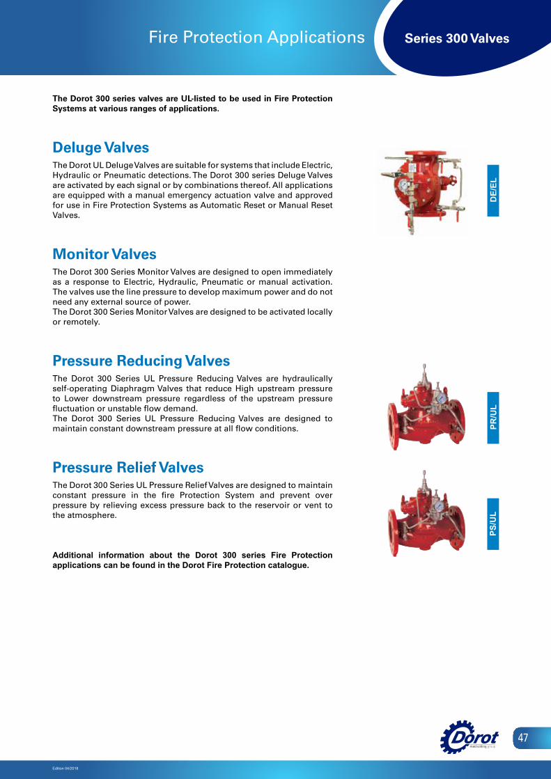
Series 300 Valves
Edition 04/2018
47
Fire Protection Applications
The Dorot 300 series valves are UL-listed to be used in Fire Protection Systems at various ranges of applications.
Deluge Valves The Dorot UL Deluge Valves are suitable for systems that include Electric, Hydraulic or Pneumatic detections. The Dorot 300 series Deluge Valves are activated by each signal or by combinations thereof. All applications are equipped with a manual emergency actuation valve and approved for use in Fire Protection Systems as Automatic Reset or Manual Reset Valves.
Monitor Valves The Dorot 300 Series Monitor Valves are designed to open immediately as a response to Electric, Hydraulic, Pneumatic or manual activation. The valves use the line pressure to develop maximum power and do not need any external source of power. The Dorot 300 Series Monitor Valves are designed to be activated locally or remotely.
Pressure Reducing Valves The Dorot 300 Series UL Pressure Reducing Valves are hydraulically self-operating Diaphragm Valves that reduce High upstream pressure to Lower downstream pressure regardless of the upstream pressure fluctuation or unstable flow demand.The Dorot 300 Series UL Pressure Reducing Valves are designed to maintain constant downstream pressure at all flow conditions.
Pressure Relief Valves The Dorot 300 Series UL Pressure Relief Valves are designed to maintain constant pressure in the fire Protection System and prevent over pressure by relieving excess pressure back to the reservoir or vent to the atmosphere.
Additional information about the Dorot 300 series Fire Protection applications can be found in the Dorot Fire Protection catalogue.
DE/
ELPR
/UL
PS/U
L

ReliabilityReliability
Innovation
ExpertiseInnovation
Expertise
Hundreds of companies in the industrial, civil engineering, municipal and agricultural sectors around the world have chosen DOROT’s innovative and field-proven technologies. Since its establishment in 1946, DOROT leads the valves market with continued innovation, uncompromising excellence and firm commitment to its customers, consulting and supporting them through all stages of a project and overcoming challenges in R&D, design, implementation, and maintenance.
www.dorot.com