series 2, 3, 4, & 5 aluminum - straight · pdf fileseries 2, 3, 4, & 5 aluminum -...
TRANSCRIPT

Series 2, 3, 4, & 5 Aluminum
Series 2, 3, 4, & 5 Aluminum - Straight Sections
I-1 B-Line series Cable Tray SystemsEaton

Series 2, 3, 4, &
5 Alum
inum
How The Service Advisor Works
We know that your time is important! That’s why the color-coding system in this catalog is designed to help youselect products that fit your service needs. Products are marked to indicate the typical lead time for orders of 50pieces or less.Customer: How do I select my straight sections. covers, or fittings so that I get the quickest turnaround?Service Advisor: Each part of our selection chart is shown in colors. If any section of a part number is a differentcolor, the part will typically ship with the longer lead time represented by the colors.
Green = Fastest shipped itemsBlack = Normal lead-time itemsRed = Normally long lead-time items
Example: 34A VT - 24 - 144 Part will have a normallead time because of the VT bottom type.
For Aluminum Fittingssee fittings section pages
L-1 thru L-17
Series 2, 3, 4, & 5 Aluminum - Accessories
I-2B-Line series Cable Tray Systems Eaton
3" NEMA VE 1 Loading Depth4" Side Rail Height
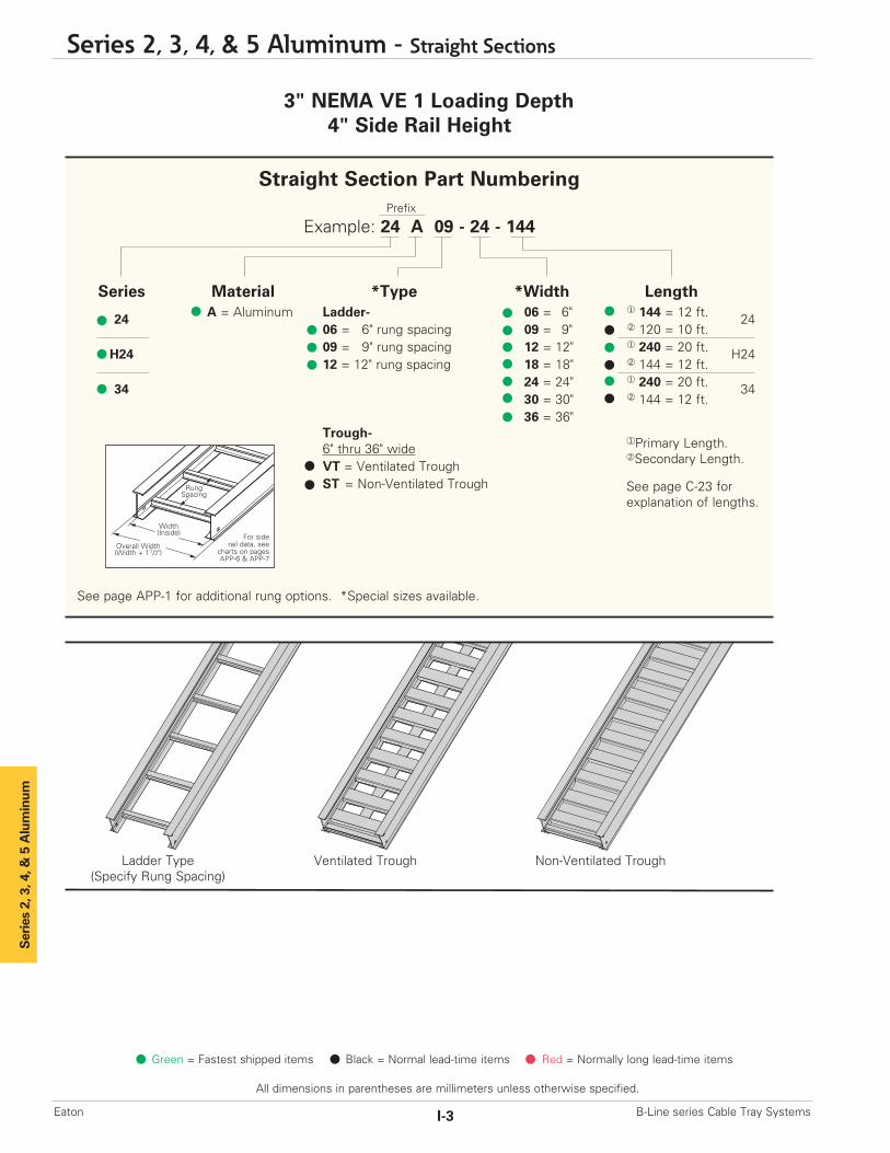
Ladder Type(Specify Rung Spacing)
Ventilated Trough Non-Ventilated Trough
Overall Width(Width + 11/2")
For siderail data, see
charts on pagesAPP-6 & APP-7
RungSpacing
Width(Inside)
Straight Section Part NumberingPrefix
Example: 24 A 09 - 24 - 144
Series Material *Type *Width Length
24 A = Aluminum Ladder- 06 = 6" ¨ 144 = 12 ft. 2406 = 6" rung spacing 09 = 9" ¡ 120 = 10 ft.
H24 09 = 9" rung spacing 12 = 12" ¨ 240 = 20 ft. H2412 = 12" rung spacing 18 = 18" ¡ 144 = 12 ft.
34 24 = 24" ¨ 240 = 20 ft. 3430 = 30" ¡ 144 = 12 ft. 36 = 36"
Trough-6" thru 36" wideVT = Ventilated TroughST = Non-Ventilated Trough
See page APP-1 for additional rung options. *Special sizes available.
Series 2, 3, 4, & 5 Aluminum
¨Primary Length.¡Secondary Length.
See page C-23 for explanation of lengths.
Green = Fastest shipped items Black = Normal lead-time items Red = Normally long lead-time items
All dimensions in parentheses are millimeters unless otherwise specified.
Series 2, 3, 4, & 5 Aluminum - Straight Sections
I-3 B-Line series Cable Tray SystemsEaton
Series 2, 3, 4, &
5 Alum
inum
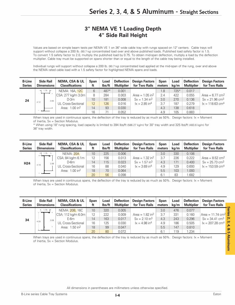
Values are based on simple beam tests per NEMA VE 1 on 36" wide cable tray with rungs spaced on 12" centers. Cable trays will support without collapse a 200 lb. (90.7 kg) concentrated load over and above published loads. Published load safety factor is 1.5. To convert 1.5 safety factor to 2.0, multiply the published load by 0.75. To obtain mid-span deflection, multiply a load by the deflectionmultiplier. Cable tray must be supported on spans shorter than or equal to the length of the cable tray being installed.
Individual rungs will support without collapse a 200 lb. (90.7 kg) concentrated load applied at the mid-span of the rung, over and abovethe NEMA rated cable load with a 1.5 safety factor for highlighted NEMA spans and loads.
When trays are used in continuous spans, the deflection of the tray is reduced by as much as 50%. Design factors: Ix = Momentof Inertia, Sx = Section Modulus.
3" NEMA VE 1 Loading Depth4" Side Rail Height
When trays are used in continuous spans, the deflection of the tray is reduced by as much as 50%. Design factors: Ix = Momentof Inertia, Sx = Section Modulus.* When using 18" rung spacing, load capacity is limited to 394 lbs/ft (586.27 kg/m) for 30" tray width and 325 lbs/ft (483.6 kg/m) for36" tray width.
When trays are used in continuous spans, the deflection of the tray is reduced by as much as 50%. Design factors: Ix = Momentof Inertia, Sx = Section Modulus.
Series 2, 3, 4, & 5 Aluminum - Straight Sections
I-4B-Line series Cable Tray Systems Eaton
All dimensions in parentheses are millimeters unless otherwise specified.
B-Line Side Rail NEMA, CSA & UL Span Load Deflection Design Factors Span Load Deflection Design FactorsSeries Dimensions Classifications ft lbs/ft Multiplier for Two Rails meters kg/m Multiplier for Two Rails
NEMA: 16A, 12C 6 487* 0.001 1.8 725* 0.017CSA: 277 kg/m 3.0m 8 284 0.003 Area = 1.05 in2 2.4 422 0.055 Area = 6.77 cm2
D-3m 10 181 0.008 Sx = 1.34 in3 3.0 270 0.136 Sx = 21.96 cm3
UL Cross-Sectional 12 126 0.016 Ix = 2.85 in4 3.7 187 0.279 Ix = 118.63 cm4
Area: 1.00 in2 14 93 0.030 4.3 138 0.61816 71 0.052 4.9 105 0.883
1.75
4.123.0524
B-Line Side Rail NEMA, CSA & UL Span Load Deflection Design Factors Span Load Deflection Design FactorsSeries Dimensions Classifications ft lbs/ft Multiplier for Two Rails meters kg/m Multiplier for Two Rails
NEMA: 20A 10 225 0.006 3.0 330 0.106CSA: 84 kg/m 6.1m 12 156 0.013 Area = 1.32 in2 3.7 226 0.222 Area = 8.52 cm2
D-6m 14 115 0.023 Sx = 1.57 in3 4.3 171 0.400 Sx = 25.73 cm3
UL Cross-Sectional 16 88 0.040 Ix = 3.69 in4 4.9 129 0.693 Ix = 153.59 cm4
Area: 1.00 in2 18 70 0.064 5.5 103 1.09320 56 0.098 6.1 83 1.682
1.75
4.192.98H24
B-Line Side Rail NEMA, CSA & UL Span Load Deflection Design Factors Span Load Deflection Design FactorsSeries Dimensions Classifications ft lbs/ft Multiplier for Two Rails meters kg/m Multiplier for Two Rails
NEMA: 20B, 16C 10 320 0.005 3.0 476 0.077CSA: 112 kg/m 6.0m 12 222 0.009 Area = 1.82 in2 3.7 331 0.160 Area = 11.74 cm2
E-6m 14 163 0.017 Sx = 2.10 in3 4.3 243 0.296 Sx = 34.41 cm3
UL Cross-Sectional 16 125 0.030 Ix = 4.98 in4 4.9 186 0.505 Ix = 207.28 cm4
Area: 1.50 in2 18 99 0.047 5.5 147 0.81020 80 0.072 6.1 119 1.234
1.75
4.203.0834

4" NEMA VE 1 Loading Depth5" Side Rail Height
Ladder Type(Specify Rung Spacing)
Ventilated Trough Non-Ventilated Trough
Series 2, 3, 4, & 5 Aluminum
Green = Fastest shipped items Black = Normal lead-time items Red = Normally long lead-time items
All dimensions in parentheses are millimeters unless otherwise specified.
Series 2, 3, 4, & 5 Aluminum - Straight Sections
I-5 B-Line series Cable Tray SystemsEaton
Overall Width(Width + 11/2")
For siderail data, see
charts on pagesAPP-6 & APP-7
RungSpacing
Width(Inside)
Straight Section Part NumberingPrefix
Example: 25 A 09 - 24 - 144
Series Material *Type *Width Length
25 A = Aluminum Ladder- 06 = 6" ¨ 144 = 12 ft. 2506 = 6" rung spacing 09 = 9" ¡ 120 = 10 ft.
35 09 = 9" rung spacing 12 = 12" ¨ 240 = 20 ft. 3512 = 12" rung spacing 18 = 18" ¡ 144 = 12 ft.
24 = 24"30 = 30"36 = 36"
Trough-6" thru 36" wideVT = Ventilated TroughST = Non-Ventilated Trough
See page APP-1 for additional rung options. *Special sizes available.
¨Primary Length.¡Secondary Length.
See page C-23 for explanation of lengths.

Values are based on simple beam tests per NEMA VE 1 on 36" wide cable tray with rungs spaced on 12" centers. Cable trays willsupport without collapse a 200 lb. (90.7 kg) concentrated load over and above published loads. Published load safety factor is 1.5. To convert 1.5 safety factor to 2.0, multiply published load by 0.75. To obtain mid-span deflection, multiply a load by the deflectionmultiplier. Cable tray must be supported on spans shorter than or equal to the length of the cable tray being installed.
Individual rungs will support without collapse a 200 lb. (90.7 kg) concentrated load applied at the mid-span of the rung, over and abovethe NEMA rated cable load with a 1.5 safety factor for highlighted NEMA spans and loads.
When trays are used in continuous spans, the deflection of the tray is reduced by as much as 50%. Design factors: Ix = Momentof Inertia, Sx = Section Modulus.
When trays are used in continuous spans, the deflection of the tray is reduced by as much as 50%. Design factors: Ix = Momentof Inertia, Sx = Section Modulus.
4" NEMA VE 1 Loading Depth5" Side Rail Height
Series 2, 3, 4, &
5 Alum
inum
Series 2, 3, 4, & 5 Aluminum - Straight Sections
I-6B-Line series Cable Tray Systems Eaton
All dimensions in parentheses are millimeters unless otherwise specified.
B-Line Side Rail NEMA, CSA & UL Span Load Deflection Design Factors Span Load Deflection Design FactorsSeries Dimensions Classifications ft lbs/ft Multiplier for Two Rails meters kg/m Multiplier for Two Rails
NEMA: 20A, 12C 10 200 0.0049 3.0 298 0.083CSA: 67 kg/m 6.0m 12 139 0.010 Area = 1.24 in2 3.7 207 0.172 Area = 8.00 cm2
D-6m 14 102 0.019 Sx = 1.80 in3 4.3 152 0.319 Sx = 29.50 cm3
UL Cross-Sectional 16 78 0.032 Ix = 4.62 in4 4.9 116 0.545 Ix = 192.30 cm4
Area: 1.00 in2 18 62 0.051 5.5 92 0.87320 50 0.078 6.1 74 1.330
1.75
5.003.9325
B-Line Side Rail NEMA, CSA & UL Span Load Deflection Design Factors Span Load Deflection Design FactorsSeries Dimensions Classifications ft lbs/ft Multiplier for Two Rails meters kg/m Multiplier for Two Rails
NEMA: 20B, 16C 10 310 0.0036 3.0 461 0.060CSA: 112 kg/m 6.0m 12 215 0.0073 Area = 1.67 in2 3.7 320 0.125 Area = 10.77 cm2
E-6m 14 158 0.014 Sx = 2.35 in3 4.3 235 0.232 Sx = 38.51 cm3
UL Cross-Sectional 16 121 0.023 Ix = 6.37 in4 4.9 180 0.395 Ix = 265.14 cm4
Area: 1.50 in2 18 96 0.037 5.5 142 0.63320 77 0.057 6.1 115 0.965
1.75
5.063.9635

5" NEMA VE 1 Loading Depth6" Side Rail Height
Ladder Type(Specify Rung Spacing)
Ventilated Trough Non-Ventilated Trough
Series 2, 3, 4, & 5 Aluminum
Green = Fastest shipped items Black = Normal lead-time items Red = Normally long lead-time items
All dimensions in parentheses are millimeters unless otherwise specified.
Series 2, 3, 4, & 5 Aluminum - Straight Sections
I-7 B-Line series Cable Tray SystemsEaton
Overall Width(Width + 11/2")
For siderail data, see
charts on pagesAPP-6 & APP-7
RungSpacing
Width(Inside)
Straight Section Part NumberingPrefix
Example: 26 A 09 - 24 - 144
Series Material *Type *Width Length
26 A = Aluminum Ladder- 06 = 6" ¨ 144 = 12 ft. 2606 = 6" rung spacing 09 = 9" ¡ 120 = 10 ft.
36 09 = 9" rung spacing 12 = 12" ¨ 240 = 20 ft. 3612 = 12" rung spacing 18 = 18" ¡ 144 = 12 ft.
46 24 = 24" ¨ 240 = 20 ft. 4630 = 30" ¡ 288 = 24 ft.
H46†36 = 36" ¨ 240 = 20 ft. H46
Trough- ¡ 300 = 25 ft.6" thru 36" wideVT = Ventilated TroughST = Non-Ventilated Trough
See page APP-1 for additional rung options. *Special sizes available.
¨Primary Length.¡Secondary Length.
See page C-23 for explanation of lengths.
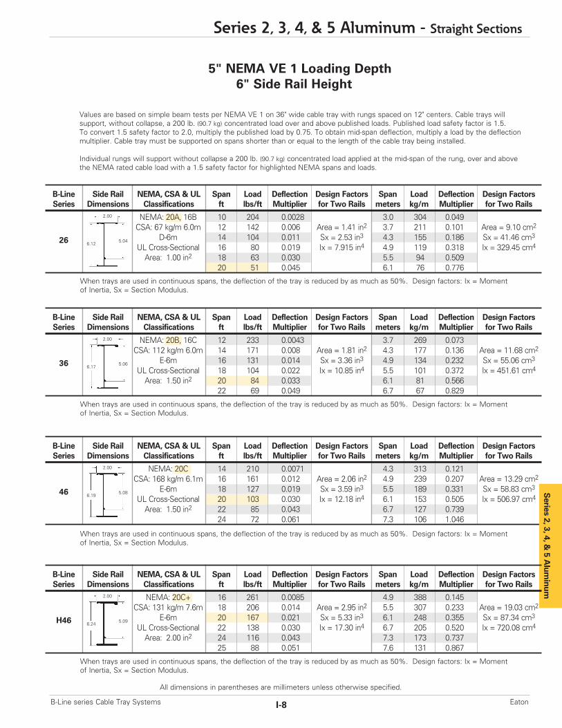
Values are based on simple beam tests per NEMA VE 1 on 36" wide cable tray with rungs spaced on 12" centers. Cable trays will support, without collapse, a 200 lb. (90.7 kg) concentrated load over and above published loads. Published load safety factor is 1.5. To convert 1.5 safety factor to 2.0, multiply the published load by 0.75. To obtain mid-span deflection, multiply a load by the deflectionmultiplier. Cable tray must be supported on spans shorter than or equal to the length of the cable tray being installed.
Individual rungs will support without collapse a 200 lb. (90.7 kg) concentrated load applied at the mid-span of the rung, over and abovethe NEMA rated cable load with a 1.5 safety factor for highlighted NEMA spans and loads.
When trays are used in continuous spans, the deflection of the tray is reduced by as much as 50%. Design factors: Ix = Momentof Inertia, Sx = Section Modulus.
5" NEMA VE 1 Loading Depth6" Side Rail Height
When trays are used in continuous spans, the deflection of the tray is reduced by as much as 50%. Design factors: Ix = Momentof Inertia, Sx = Section Modulus.
When trays are used in continuous spans, the deflection of the tray is reduced by as much as 50%. Design factors: Ix = Momentof Inertia, Sx = Section Modulus.
When trays are used in continuous spans, the deflection of the tray is reduced by as much as 50%. Design factors: Ix = Momentof Inertia, Sx = Section Modulus.
Series 2, 3, 4, & 5 Aluminum - Straight Sections
I-8B-Line series Cable Tray Systems Eaton
All dimensions in parentheses are millimeters unless otherwise specified.
B-Line Side Rail NEMA, CSA & UL Span Load Deflection Design Factors Span Load Deflection Design FactorsSeries Dimensions Classifications ft lbs/ft Multiplier for Two Rails meters kg/m Multiplier for Two Rails
NEMA: 20A, 16B 10 204 0.0028 3.0 304 0.049CSA: 67 kg/m 6.0m 12 142 0.006 Area = 1.41 in2 3.7 211 0.101 Area = 9.10 cm2
D-6m 14 104 0.011 Sx = 2.53 in3 4.3 155 0.186 Sx = 41.46 cm3
UL Cross-Sectional 16 80 0.019 Ix = 7.915 in4 4.9 119 0.318 Ix = 329.45 cm4
Area: 1.00 in2 18 63 0.030 5.5 94 0.50920 51 0.045 6.1 76 0.776
2.00
6.125.0426
B-Line Side Rail NEMA, CSA & UL Span Load Deflection Design Factors Span Load Deflection Design FactorsSeries Dimensions Classifications ft lbs/ft Multiplier for Two Rails meters kg/m Multiplier for Two Rails
NEMA: 20B, 16C 12 233 0.0043 3.7 269 0.073CSA: 112 kg/m 6.0m 14 171 0.008 Area = 1.81 in2 4.3 177 0.136 Area = 11.68 cm2
E-6m 16 131 0.014 Sx = 3.36 in3 4.9 134 0.232 Sx = 55.06 cm3
UL Cross-Sectional 18 104 0.022 Ix = 10.85 in4 5.5 101 0.372 Ix = 451.61 cm4
Area: 1.50 in2 20 84 0.033 6.1 81 0.56622 69 0.049 6.7 67 0.829
2.00
6.175.0636
B-Line Side Rail NEMA, CSA & UL Span Load Deflection Design Factors Span Load Deflection Design FactorsSeries Dimensions Classifications ft lbs/ft Multiplier for Two Rails meters kg/m Multiplier for Two Rails
NEMA: 20C 14 210 0.0071 4.3 313 0.121CSA: 168 kg/m 6.1m 16 161 0.012 Area = 2.06 in2 4.9 239 0.207 Area = 13.29 cm2
E-6m 18 127 0.019 Sx = 3.59 in3 5.5 189 0.331 Sx = 58.83 cm3
UL Cross-Sectional 20 103 0.030 Ix = 12.18 in4 6.1 153 0.505 Ix = 506.97 cm4
Area: 1.50 in2 22 85 0.043 6.7 127 0.73924 72 0.061 7.3 106 1.046
2.00
6.195.0846 S
eries 2, 3, 4, & 5 A
luminum
B-Line Side Rail NEMA, CSA & UL Span Load Deflection Design Factors Span Load Deflection Design FactorsSeries Dimensions Classifications ft lbs/ft Multiplier for Two Rails meters kg/m Multiplier for Two Rails
NEMA: 20C+ 16 261 0.0085 4.9 388 0.145CSA: 131 kg/m 7.6m 18 206 0.014 Area = 2.95 in2 5.5 307 0.233 Area = 19.03 cm2
E-6m 20 167 0.021 Sx = 5.33 in3 6.1 248 0.355 Sx = 87.34 cm3
UL Cross-Sectional 22 138 0.030 Ix = 17.30 in4 6.7 205 0.520 Ix = 720.08 cm4
Area: 2.00 in2 24 116 0.043 7.3 173 0.73725 88 0.051 7.6 131 0.867
2.00
6.245.09H46

6" NEMA VE 1 Loading Depth7" Side Rail Height
Ladder Type(Specify Rung Spacing)
57A available in(9” & 12” rung spacing in
12” to 36” widths)
Ventilated Trough Non-Ventilated Trough
Series 2, 3, 4, & 5 Aluminum
Green = Fastest shipped items Black = Normal lead-time items Red = Normally long lead-time items
All dimensions in parentheses are millimeters unless otherwise specified.
Series 2, 3, 4, & 5 Aluminum - Straight Sections
I-9 B-Line series Cable Tray SystemsEaton
Overall Width(Width + 11/2")
For siderail data, see
charts on pagesAPP-6 & APP-7
RungSpacing
Width(Inside)
Straight Section Part NumberingPrefix
Example: 37 A 09 - 24 - 144
Series Material *Type *Width Length
27 A = Aluminum Ladder- 06 = 6" ¨ 144 = 12 ft. 2706 = 6" rung spacing 09 = 9" ¡ 120 = 10 ft.
37 09 = 9" rung spacing 12 = 12" ¨ 240 = 20 ft. 3712 = 12" rung spacing 18 = 18" ¡ 144 = 12 ft.
47 24 = 24" ¨ 240 = 20 ft. 4730 = 30" ¡ 288 = 24 ft.
H47†36 = 36" ¨ 240 = 20 ft. H47
¡ 300 = 25 ft.
57¨ 360 = 30 ft. 57
Trough- ¡ 300 = 25 ft.6" thru 36" wideVT = Ventilated TroughST = Non-Ventilated Trough
† H47A & 57A only available in laddertype 9” and 12” rung spacing.See page APP-2.
See page APP-1 for additional rung options. *Special sizes available.
¨Primary Length.¡Secondary Length.
See page C-23 for explanation of lengths.

Series 2, 3, 4, &
5 Alum
inum
B-Line Side Rail NEMA, CSA & UL Span Load Deflection Design Factors Span Load Deflection Design FactorsSeries Dimensions Classifications ft lbs/ft Multiplier for Two Rails meters kg/m Multiplier for Two Rails
NEMA: 12C 10 177 0.006 3.0 269 0.033CSA: 68 kg/m 6.0m 12 123 0.013 Area = 1.63 in2 3.7 177 0.073 Area = 10.52 cm2
D-6m 14 90 0.023 Sx = 2.93 in3 4.3 134 0.131 Sx = 48.01 cm3
UL Cross-Sectional 16 69 0.040 Ix = 11.28 in4 4.9 101 0.227 Ix = 469.51 cm4
Area: 1.50 in2 18 54 0.064 5.5 81 0.35720 44 0.098 6.1 67 0.534
Values are based on simple beam tests per NEMA VE 1 on 36" wide cable tray with rungs spaced on 12" centers. Cable trays willsupport without collapse a 200 lb. (90.7 kg) concentrated load over and above published loads. Published load safety factor is 1.5. To convert 1.5 safety factor to 2.0, multiply the published load by 0.75. To obtain mid-span deflection, multiply a load by thedeflection multiplier. Cable tray must be supported on spans shorter than or equal to the length of the cable tray being installed.
Individual rungs will support without collapse a 200 lb. (90.7 kg) concentrated load applied at the mid-span of the rung, over and abovethe NEMA rated cable load with a 1.5 safety factor for highlighted NEMA spans and loads.
2.00
7.146.00
6" NEMA VE 1 Loading Depth7" Side Rail Height
27
B-Line Side Rail NEMA, CSA & UL Span Load Deflection Design Factors Span Load Deflection Design FactorsSeries Dimensions Classifications ft lbs/ft Multiplier for Two Rails meters kg/m Multiplier for Two Rails
NEMA: 20B, 16C 12 222 0.0035 3.7 331 0.059CSA: 101 kg/m 6.1m 14 163 0.0064 Area = 1.81 in2 4.3 243 0.109 Area = 11.68 cm2
D-6m 16 125 0.011 Sx = 3.77 in3 4.9 186 0.186 Sx = 61.78 cm3
UL Cross-Sectional 18 99 0.017 Ix = 13.50 in4 5.5 147 0.299 Ix = 561.91 cm4
Area: 1.50 in2 20 80 0.027 6.1 119 0.45522 66 0.039 6.7 98 0.666
2.00
7.146.0537
B-Line Side Rail NEMA, CSA & UL Span Load Deflection Design Factors Span Load Deflection Design FactorsSeries Dimensions Classifications ft lbs/ft Multiplier for Two Rails meters kg/m Multiplier for Two Rails
NEMA: 20C 14 204 0.0048 4.3 305 0.083CSA: 142 kg/m 6.1m 16 156 0.0082 Area = 2.38 in2 4.9 233 0.141 Area = 15.35 cm2
E-6m 18 123 0.0132 Sx = 4.94 in3 5.5 184 0.225 Sx = 80.95 cm3
UL Cross-Sectional 20 100 0.0201 Ix = 17.88 in4 6.1 149 0.344 Ix = 744.22 cm4
Area: 2.00 in2 22 83 0.0295 6.7 123 0.50324 69 0.0418 7.3 103 0.713
2.00
7.246.1347
B-Line Side Rail NEMA, CSA & UL Span Load Deflection Design Factors Span Load Deflection Design FactorsSeries Dimensions Classifications ft lbs/ft Multiplier for Two Rails meters kg/m Multiplier for Two Rails
NEMA: 20C+ 16 233 0.0064 4.9 346 0.110CSA: 241 kg/m 6.1m 18 184 0.010 Area = 3.04 in2 5.4 274 0.176 Area = 19.61 cm2
E-6m 20 149 0.016 Sx = 6.10 in3 6.1 222 0.268 Sx = 99.96 cm3
UL Cross-Sectional 22 123 0.023 Ix = 22.91 in4 6.7 183 0.393 Ix = 953.59 cm4
Area: 2.00 in2 24 103 0.033 7.3 154 0.55625 95 0.038 7.6 142 0.655
2.00
7.246.09H47
B-Line Side Rail NEMA, CSA & UL Span Load Deflection Design Factors Span Load Deflection Design FactorsSeries Dimensions Classifications ft lbs/ft Multiplier for Two Rails meters kg/m Multiplier for Two Rails
NEMA: 20C+ 20 232 0.011 6.1 345 0.187CSA: 151 kg/m 9.1m 22 192 0.016 Area = 4.22 in2 6.7 285 0.274 Area = 27.73 cm2
E-6m 24 161 0.023 Sx = 7.73 in3 7.3 240 0.388 Sx = 126.67 cm3
UL Cross-Sectional 26 136 0.031 Ix = 32.86 in4 7.9 202 0.534 Ix = 1367.74 cm4
Area: 2.00 in2 28 117 0.042 8.5 174 0.71830 102 0.055 9.1 152 0.947
2.00
7.406.2357
When trays are used in continuous spans, the deflection of the tray is reduced by as much as 50%. Design factors: Ix = Momentof Inertia, Sx = Section Modulus.
Series 2, 3, 4, & 5 Aluminum - Straight Sections
I-10B-Line series Cable Tray Systems Eaton
All dimensions in parentheses are millimeters unless otherwise specified.
6" NEMA VE 1 Loading Depth8" Side Rail Height
Series 2, 3, 4, & 5 Aluminum
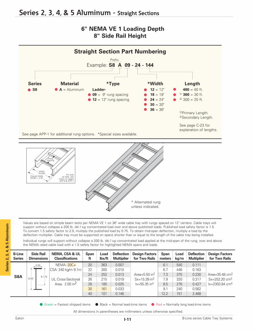
* Alternated rung unless indicated.
B-Line Side Rail NEMA, CSA & UL Span Load Deflection Design Factors Span Load Deflection Design FactorsSeries Dimensions Classifications ft lbs/ft Multiplier for Two Rails meters kg/m Multiplier for Two Rails
NEMA: 20C+ 20 363 0.007 6.1 540 0.111CSA: 240 kg/m 9.1m 22 300 0.010 6.7 446 0.163
24 252 0.013 Area=5.50 in2 7.3 375 0.230 Area=35.48 cm2
UL Cross-Sectional 26 215 0.019 Sx=15.39 in3 7.9 320 0.317 Sx=252.20 cm3
Area: 2.00 in2 28 185 0.025 Ix=55.35 in4 8.5 276 0.427 Ix=2303.84 cm4
30 161 0.033 9.1 240 0.56240 101 0.146 12.2 151 2.488
3.00
8.006.175S8A
Overall Width(Width + 2.0")
For siderail data, see
charts on pagesAPP-6 & APP-7
RungSpacing
Width(Inside)
Values are based on simple beam tests per NEMA VE 1 on 36" wide cable tray with rungs spaced on 12" centers. Cable trays willsupport without collapse a 200 lb. (90.7 kg) concentrated load over and above published loads. Published load safety factor is 1.5. To convert 1.5 safety factor to 2.0, multiply the published load by 0.75. To obtain mid-span deflection, multiply a load by thedeflection multiplier. Cable tray must be supported on spans shorter than or equal to the length of the cable tray being installed.
Individual rungs will support without collapse a 200 lb. (90.7 kg) concentrated load applied at the mid-span of the rung, over and abovethe NEMA rated cable load with a 1.5 safety factor for highlighted NEMA spans and loads.
Green = Fastest shipped items Black = Normal lead-time items Red = Normally long lead-time items
All dimensions in parentheses are millimeters unless otherwise specified.
Series 2, 3, 4, & 5 Aluminum - Straight Sections
I-11 B-Line series Cable Tray SystemsEaton
Straight Section Part NumberingPrefix
Example: S8 A 09 - 24 - 144
Series Material *Type *Width LengthS8 A = Aluminum Ladder- 12 = 12" 480 = 40 ft.
09 = 9" rung spacing 18 = 18" ¨ 360 = 30 ft.12 = 12" rung spacing 24 = 24" ¡ 300 = 25 ft.
30 = 30"36 = 36"
See page APP-1 for additional rung options. *Special sizes available.
¨Primary Length.¡Secondary Length.
See page C-23 for explanation of lengths.

Series 2, 3, 4, &
5 Alum
inum
The following is a list of accessories and fittings that can be provided with S8A tray.For more information on these items, contact our Engineering Department.
Fittings
Horizontal Bends30° Bends with 24”, 36”, or 48” radius45° Bends with 24”, 36”, or 48” radius60° Bends with 24”, 36”, or 48” radius90° Bends with 24”, 36”, or 48” radius
Horizontal Tees & CrossesWith 24”, 36”, or 48” radius
Vertical Outside Bends30° Bends with 24”, 36”, or 48” radius45° Bends with 24”, 36”, or 48” radius60° Bends with 24”, 36”, or 48” radius90° Bends with 24”, 36”, or 48” radius
Vertical Inside Bends30° Bends with 24”, 36”, or 48” radius45° Bends with 24”, 36”, or 48” radius60° Bends with 24”, 36”, or 48” radius90° Bends with 24”, 36”, or 48” radius
Reducing Fittings
Accessories - (standard hardware is stainless steel Type 316)
Splice Plate - 9A-1008Expansion Splice Plate - 9A-1018Horizontal Adjustable Splice Plate - 9A-1038Vertical Adjustable Splice Plate - 9A-1028Hold Down Clamps - 9ZN-1281, 9G-1281, 9A-1281Guides - S9ZN-1202, S9G-1202Step Down Splice Plate -
9A-1048 = 8” to 4”9A-1051 = 8” to 5”9A-1050 = 8” to 6”9A-1078 = 8” to 7”
Other Accessories Include:Offset Splice PlatesBlind Ends
Covers - Standard aluminum cover number with S in front (Example: S807A40)
Green = Fastest shipped items Black = Normal lead-time items Red = Normally long lead-time items
Series 2, 3, 4, & 5 Aluminum - Accessories
I-12B-Line series Cable Tray Systems Eaton
All dimensions in parentheses are millimeters unless otherwise specified.

Catalog No. Heightin. mm
9A-1004 4 (101)9A-1005 5 (127)9A-1006 6 (152)9A-1007 7 (178)
Series 2, 3, 4, & 5 Aluminum
Catalog No. Heightin. mm
9A-1014 4 (101)9A-1015 5 (127)9A-1016 6 (152)9A-1017 7 (178)
Catalog No. Heightin. mm
9A-1004-1/2 4 (101)9A-1005-1/2 5 (127)9A-1006-1/2 6 (152)9A-1007-1/2 7 (178)
Catalog No. Heightin. mm
9A-1045 5 to 4 (127 to 101)9A-1046 6 to 4 (152 to 101)9A-1060 6 to 5 (152 to 127)9A-1047 7 to 4 (178 to 101)9A-1061 7 to 5 (178 to 127)9A-1062 7 to 6 (178 to 152)
Catalog No. Heightin. mm
9A-1024 4 (101)9A-1025 5 (127)9A-1026 6 (152)9A-1027 7 (178)
Catalog No. TraySeries
9A-6006 H46A9A-6007 H47A, 57A
Requires supports within 24” onboth sides, per NEMA VE 2.
Green = Fastest shipped items Black = Normal lead-time items Red = Normally long lead-time items
All dimensions in parentheses are millimeters unless otherwise specified.
Series 2, 3, 4, & 5 Aluminum - Accessories
I-13 B-Line series Cable Tray SystemsEaton
Wedge Lock Splice Plates
• Furnished in pairs with 1/4" hardware.• Standard 4-hole pattern.• Furnished in pairs, with hardware.• One pair including hardware provided with each section.(Expansion splice quantity subtracted)
• Boxed in pairs with hardware.• For field installation drill 13/32" hole.
Expansion Splice Plates
• Expansion plates allow for one inch expansion or contraction of the cable tray, or where expansion joints occur in thesupporting structure.
• Furnished in pairs with hardware.• Bonding Jumpers are required on each siderail.Order Separately.
For heavy duty expansion splice plates see page APP-3.
Universal Splice Plates
• Furnished in pairs with 1/4" hardware.• UL Classified.
Step Down Splice Plates
• These splice plates are offered for connecting cable tray sections having side rails of different heights.
• Furnished in pairs with hardware.
H46A, H47A and 57A Mid-Span Splice
• Furnished in pairs with 1/4" hardware.• Standard for H46A, H47A and 57A straight sections.• Six bolt design 1/2" Stainless Steel Type 316 hardware standard.
• Available on ladder bottoms only. 09 and 12" rung spacing.• Furnished in pairs with hardware.
Vertical Adjustable Splice Plates
• These plates provide for changes in elevation thatdo not conform to standard vertical fittings.
• Furnished in pairs with hardware.• Bonding Jumpers not required.
Series 2, 3, 4, &
5 Alum
inum
Green = Fastest shipped items Black = Normal lead-time items Red = Normally long lead-time items
Series 2, 3, 4, & 5 Aluminum - Accessories
I-14B-Line series Cable Tray Systems Eaton
All dimensions in parentheses are millimeters unless otherwise specified.
Offset Reducing Splice Plate
• This plate is used for joining cable trays having different widths.When used in pairs they form a straight reduction; when usedsingly with a standard splice plate, they form an offset reduction.
• Furnished as one plate with hardware.• (‡) Insert reduction
Frame Type Box Connector• Designed to attach the end of a cable tray run to a distributioncabinet or control center to help reinforce the box at thepoint of entry.
• Furnished with tray connection hardware.
Blind End• This plate forms a closure for a dead end cable tray.• Furnished as one plate with hardware.• (‡) Insert tray width
Tray to Box Splice Plates• Used to attach the end of a cable tray run to a distributionbox or control panel.
• Furnished in pairs with hardware
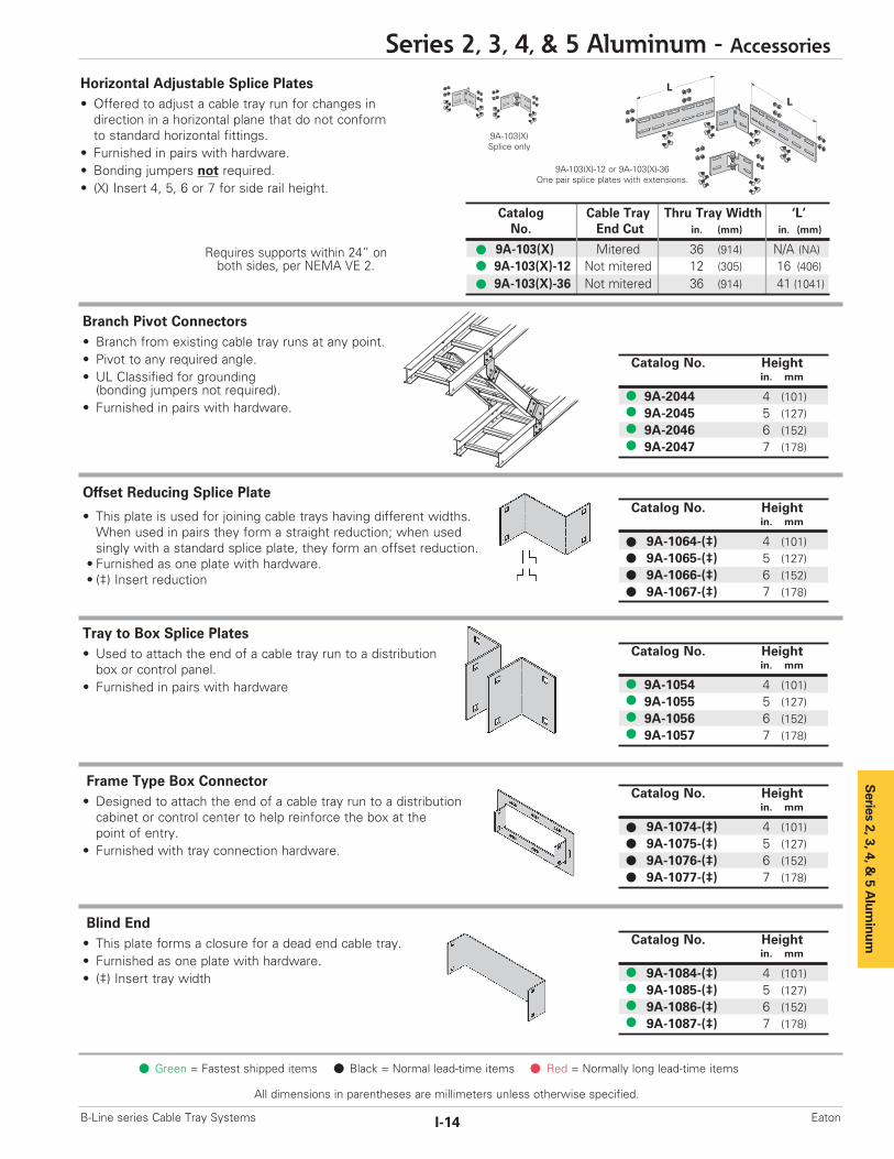
Horizontal Adjustable Splice Plates• Offered to adjust a cable tray run for changes indirection in a horizontal plane that do not conform to standard horizontal fittings.
• Furnished in pairs with hardware.• Bonding jumpers not required.• (X) Insert 4, 5, 6 or 7 for side rail height.
Branch Pivot Connectors• Branch from existing cable tray runs at any point.• Pivot to any required angle.• UL Classified for grounding (bonding jumpers not required).
• Furnished in pairs with hardware.
Catalog Cable Tray Thru Tray Width ‘L’No. End Cut in. (mm) in. (mm)
9A-103(X) Mitered 36 (914) N/A (NA)9A-103(X)-12 Not mitered 12 (305) 16 (406)9A-103(X)-36 Not mitered 36 (914) 41 (1041)
9A-103(X)Splice only
9A-103(X)-12 or 9A-103(X)-36One pair splice plates with extensions.
LL
Requires supports within 24” onboth sides, per NEMA VE 2.
Catalog No. Heightin. mm
9A-2044 4 (101)9A-2045 5 (127)9A-2046 6 (152)9A-2047 7 (178)
Catalog No. Heightin. mm
9A-1054 4 (101)9A-1055 5 (127)9A-1056 6 (152)9A-1057 7 (178)
Catalog No. Heightin. mm
9A-1064-(‡) 4 (101)9A-1065-(‡) 5 (127)9A-1066-(‡) 6 (152)9A-1067-(‡) 7 (178)
Catalog No. Heightin. mm
9A-1084-(‡) 4 (101)9A-1085-(‡) 5 (127)9A-1086-(‡) 6 (152)9A-1087-(‡) 7 (178)
Catalog No. Heightin. mm
9A-1074-(‡) 4 (101)9A-1075-(‡) 5 (127)9A-1076-(‡) 6 (152)9A-1077-(‡) 7 (178)

Series 2, 3, 4, & 5 Aluminum
All dimensions in parentheses are millimeters unless otherwise specified.
Series 2, 3, 4, & 5 Aluminum - Accessories
I-15 B-Line series Cable Tray SystemsEaton
Catalog No. Description
SNCB 3/8” x 3/4” ZN Square Neck Carriage Bolt ASTM A307 Grade A
SFHN 3/8”-16 ZN Serrated Flange Hex Nut ASTM A563 Grade A
Catalog No.
9A-1240
Catalog No.
9ZN-1150-(‡)
Catalog No.
9ZN-1155-(‡)
Catalog No.
99-2125-15
Catalog No. Conduit Sizein. mm
9G-1158-1/2, 3/2 1/2, 3/4 (15, 20)9G-1158-1, 11/4 1, 11/4 (25, 32)9G-1158-11/2, 2 11/2, 2 (40, 50)9G-1158-21/2, 3 21/2, 3 (65, 80)9G-1158-31/2, 4 31/2, 4 (90, 100)
Green = Fastest shipped items Black = Normal lead-time items Red = Normally long lead-time items
Standard Tray Hardware (for field installation drill 13/32” hole)
• Finish: Zinc Plated ASTM B633 SC1
Cross Connector Bracket
• For field connecting crossing section.• Furnished in pairs with 3/8" hardware.
Conduit to Cable Tray Adaptor
• For easy attachment of conduit terminatingat a cable tray.
• Use on aluminum or steel cable trays.
Conduit to Cable Tray Adaptor
• Assembly required.• Mounting hardware included.• Conduit clamps provided.• (‡) = Insert conduit size (1/2" thru 4").
Cable Tie (Ladder Tray)
• Nylon ties provide easy attachment of cable to ladder rungs; maximum cable O.D. is 3" (76mm).
Conduit to Cable Tray Adaptor
• Assembly required.• Conduit clamps included.• (‡) = Insert conduit size (1/2" thru 4").
Catalog No. Description
SNCB 3/8” x 3/4” SS6 Square Neck Carriage Bolt AISI 316 Stainless Steel
SFHN 3/8”-16 SS6 Serrated Flange Hex Nut AISI 316 Stainless Steel
Optional Tray Hardware (for field installation drill 13/32” hole)
• To order 316 stainless steel hardwareadd SS6 suffix to catalog number -Example: 9A1004SS6
AluminumI-Beam
Overall Length 15" (381mm)

Series 2, 3, 4, &
5 Alum
inum
Series 2, 3, 4, & 5 Aluminum - Accessories
I-16B-Line series Cable Tray Systems Eaton
All dimensions in parentheses are millimeters unless otherwise specified.
Green = Fastest shipped items Black = Normal lead-time items Red = Normally long lead-time items
Barrier - Straight Section
• Length: Insert 120 for [120” - 10 ft.] (3.0 m)or 144 for [144" - 12 ft.] (3.6 m)
• Order catalog number based on loading depth.• Furnished with four #10 x 1/2" platedself-drilling screws and a 99-9982 Barrier Strip Splice.
Barrier - Vertical Outside Bend• Vertical Outside Bend Barriers are preformed to conformto a specific vertical outside bend fitting.
• Furnished with three #10 x 1/2" plated self-drilling screws and a 99-9982 Barrier Strip Splice.
• (*) Insert 30, 45, 60 or 90 for degrees• (†) Insert 12, 24, 36 or 48 for radius
Barrier - Vertical Inside Bend• Vertical Inside Bend Barriers are preformed to conformto a specific vertical inside bend fitting.
• Furnished with three #10 x 1/2" plated self-drilling screws and a 99-9982 Barrier Strip Splice.
• (*) Insert 30, 45, 60 or 90 for degrees• (†) Insert 12, 24, 36 or 48 for radius
Barrier - Horizontal Bend
• Horizontal Bend Barriers are flexible in order to conform to any horizontal fitting radius. Can be cut to desired length.
• Standard length is 72" [6 ft.] (1.8 m) - sold individually• Order catalog number based on loading depth.• Furnished with three #10 x 1/2" platedself-drilling screws and a 99-9982 Barrier Strip Splice.
Ladder Drop-Out• Specially-designed Ladder Drop-Outs provide a rounded surface with 4" (101 mm) radius to protect cable as it exits from the cable tray, preventing damage to insulation.The drop-out will attach to any desired rung.
• (‡) Insert tray width
Trough Drop-Out & Drop-Out Bushing• These devices provide a rounded surface to protect cableas it exits from the trough-type cable tray.
• Hardware is included for attachment of the troughbottom drop-out.
• (‡) Insert tray width Snap-In Plastic BushingTrough-Type Drop-Out
Catalog No.
9A-1104-(‡)
Catalog No.
99-1124
Catalog No.
9A-1104T-(‡)
Catalog Side Rail LoadingNo. Height Depth 'H'
in. mm in. mm
73A-Length 4 (101) 3 (76)74A-Length 5 (127) 4 (101)75A-Length 6 (152) 5 (127)76A-Length 7 (178) 6 (152)
H
H
Catalog Side Rail LoadingNo. Height Depth 'H'
in. mm in. mm
73A-90HBFL 4 (101) 3 (76)74A-90HBFL 5 (127) 4 (101)75A-90HBFL 6 (152) 5 (127)76A-90HBFL 7 (178) 6 (152)
Catalog Side Rail LoadingNo. Height Depth 'H'
in. mm in. mm
73A-(*)VO(†) 4 (101) 3 (76)74A-(*)VO(†) 5 (127) 4 (101)75A-(*)VO(†) 6 (152) 5 (127)76A-(*)VO(†) 7 (178) 6 (152)
Catalog Side Rail LoadingNo. Height Depth 'H'
in. mm in. mm
73A-(*)VI(†) 4 (101) 3 (76)74A-(*)VI(†) 5 (127) 4 (101)75A-(*)VI(†) 6 (152) 5 (127)76A-(*)VI(†) 7 (178) 6 (152)
Outside Bend(VO)
Inside Bend(VI)
H
H
Series 2, 3, 4, & 5 Aluminum
All dimensions in parentheses are millimeters unless otherwise specified.
Series 2, 3, 4, & 5 Aluminum - Accessories
I-17 B-Line series Cable Tray SystemsEaton
Screw slot forsheet metal screw
Rung
B655Rod Coupling
BarrierFlange
Catalog No.
99-9982
Green = Fastest shipped items Black = Normal lead-time items Red = Normally long lead-time items
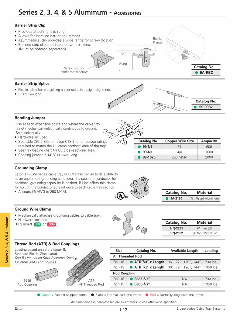
Barrier Strip Clip
• Provides attachment to rung.• Allows for installed barrier adjustment.• Asymmetrical clip provides a wide range for screw location.• Barriers strip clips not included with barriers.(Must be ordered separately)
Barrier Strip Splice
• Plastic splice holds adjoining barrier strips in straight alignment.• 3” (76mm) long.
Bonding Jumper
Use at each expansion splice and where the cable tray is not mechanically/electrically continuous to ground. Sold individually.• Hardware included.• See table 392.6(B)(2) on page CTS-9 for amperage ratingsrequired to match the UL cross-sectional area of the tray.
• See tray loading chart for UL cross-sectional area.• Bonding jumper is 141/2" (368mm) long.
Grounding Clamp
Eaton’s B-Line series cable tray is UL® classified as to its suitabilityas an equipment grounding conductor. If a separate conductor foradditional grounding capability is desired, B-Line offers this clamp for bolting the conductor at least once to each cable tray section.• Accepts #6 AWG to 250 MCM.
Thread Rod (ATR) & Rod CouplingsLoading based on safety factor 5.Standard Finish: Zinc platedSee B-Line series Strut Systems Catalogfor other sizes and finishes.
Ground Wire Clamp
• Mechanically attaches grounding cables to cable tray.• Hardware included.• (*) Insert or
Catalog No.
9A-RBC
Catalog No. Material9A-2130 Tin Plated Aluminum
Catalog No. Copper Wire Size Ampacity
99-N1 #1 60099-40 4/0 160099-1620 250 MCM 2000
Size Catalog No. Available Length Loading
All Threaded Rod3/8”-16 ATR 3/8” x Length 36”, 72”, 120”, 144” 730 lbs.1/2”-13 ATR 1/2” x Length 36”, 72”, 120”, 144” 1350 lbs.
Rod Coupling3/8”-16 B655-3/8” NA 730 lbs.1/2”-13 B655-1/2” NA 1350 lbs.
Catalog No. Material9(*)-2351 #1 thru 2/09(*(-2352 3/0 thru 250 MCM
ZN SS4
ATRAll Threaded Rod

Catalog No. Cable Sizein. mm
BP081SS .250 - .840 (6.4 - 21.3)
BP110SS .810 - 1.100 (20.6 - 28.0)
BP135SS .850 - 1.350 (21.6 - 34.8)
BP175SS 1.250 - 1.750 (31.8 - 44.5)
BP205SS 1.550 - 2.050 (39.4 - 52.1)
BP250SS 2.000 - 2.500 (50.8 - 63.5)
BP300SS 2.500 - 3.000 (63.5 - 76.2)
BP325SS 2.750 - 3.250 (69.9 - 82.6)
BP375SS 3.250 - 3.750 (82.6 - 95.3)
BP425SS 3.750 - 4.250 (95.3 - 108.0)
BP475SS 4.250 - 4.750 (108.0 - 120.7)
Series 2, 3, 4, &
5 Alum
inum
Refer to Section CFCable Fixing
Series 2, 3, 4, & 5 Aluminum - Accessories
I-18B-Line series Cable Tray Systems Eaton
All dimensions in parentheses are millimeters unless otherwise specified.
Green = Fastest shipped items Black = Normal lead-time items Red = Normally long lead-time items
Isolator Pad• Use as a friction reducer and/or as a dissimilar metal isolator barrier.• UV resistant HDPE.• Temperature range: -100 to 160° F.• Designed to use with 9(*)-1205 or 9(*)-1208 clamp/guide.• Color - White.
Cable Tray Clamp/Guide• Features a no-twist design.• Has four times the strength of the traditional design.• Each side is labeled to ensure proper installation.• Furnished in pairs, with or without hardware.• Not recommended for vertical support.
Stainless Steel Cable Clamp ‘P’• Fits with series 2, 3, & 4 rungs.• Attaches to rung at any point.• 14 gauge Type 316 stainless steel material to minimizecorrosion and induction heating.
• Plated steel and aluminum also available.
Catalog No.
99-PE34
Hanger Rod Clamp
• For 1/2" ATR.• Furnished in pairs.• Order ATR and hex nuts separately.• Two-piece "J"-hanger design.• 1500 lbs./pair capacity safety factor 3. • (*) Insert orZN G
Catalog No. Heightin. mm
9(*)-5324 4 (101)9(*)-5325 5 (127)9(*)-5326 6 (152)9(*)-5327 7 (178)
Note: For heavy duty or vertical applications see 9(*)-1241 or 9(*)-1242 page HAT-20
Catalog No.Without With Overall HardwareHardware Hardware Length Size Finish
in. (mm) in.
9ZN-1204 9ZN-1204NB 11/2 (38) 1/4" G909ZN-1208 9ZN-1208NB 21/4 (57) 3/8" G909A-1205 -- 21/4 (57) 1/2" Alum.9G-1205 -- 21/4 (57) 1/2" HDGAF9SS6-1205 -- 21/4 (57) 1/2" 316SS9ZN-1205 -- 21/4 (57) 1/2" G909ZN-1204 shown.
Installed as a guide.9ZN-1208 shown.Installed as a clamp.
Patent # RE35479
11/2"(39mm)
21/4"(57mm)
Isolation pad shown aswhen used with a guide.
Isolation pad shown with topflange doubled under forclamp application.

1/8"(3mm)
3"(76mm)
6"(152mm)
Series 2, 3, 4, & 5 Aluminum
All dimensions in parentheses are millimeters unless otherwise specified.
Series 2, 3, 4, & 5 Aluminum - Accessories
I-19 B-Line series Cable Tray SystemsEaton
Green = Fastest shipped items Black = Normal lead-time items Red = Normally long lead-time items
Cable Tray Clamp
• Hold-down clamps for single or double cable tray runs.• No drilling of support I-beam or channel is required.• Sold in pieces - two clamps are required per tray.• Maximum beam flange thickness 11/8" (28.58 mm).
Cable Tray Guide
• Expansion guide for single or double cable tray runs.• Guide allows for longitudinal movement of the cable tray.• No field drilling of support I-beam or channel is required.• Guides are required on both sides of cable tray to preventlateral movement - can be placed on either the inside oroutside flange of cable tray.
• Guides are sold in pieces - two guides are required per tray.• Maximum flange thickness 11/8" (28.58 mm).
Nylon Pad
• Use for friction reduction.• Hardness: Shore D80.• Low friction coefficient.• UV resistant.• Excellent weatherability.• UL - 94HB.
Neoprene Roll
• Use for material isolation.• 1/8" x 2" x 25' roll.• Hardness: Shore A60.• Good weatherability.
DURA-BLOK™ Rooftop Support Bases with B22 Channel• Designed as a superior rooftop supportfor cable tray,
• UV resistant and approved for mostroofing material or other flat surfaces.
• Can be used with any of B-Line series cable tray clamps and guides.
• Ultimate Load Capacity:1,000 lbs. (uniform load)
Catalog No.
99-PE36
Catalog No.
99-NP300
Catalog No. Finish9ZN-1249HD Znplt
9G-1249HD HDGAF
Catalog No. Finish9ZN-1249 Znplt
9G-1249 HDGAF
Catalog No. Height x Width x Lengthin. (mm)
DB10-28 55/8 x 6 x 28.0 (143 x 152 x 711)
DB10-36 55/8 x 6 x 36.0 (143 x 152 x 914)
DB10-42 55/8 x 6 x 42.0 (143 x 152 x 1067)
DB10-50 55/8 x 6 x 50.0 (143 x 152 x 1270)
DB10-60 55/8 x 6 x 60.0 (143 x 152 x 1524)
LEEDS credit available, base made from 100% recycled material.
General Note: Consult roofing manufacturer or engineer for roof loadcapacity. The weakest point may be the insulation board beneaththe rubber membrane.
Series 2, 3, 4, &
5 Alum
inum
Series 2, 3, 4, & 5 Aluminum - Accessories
I-20B-Line series Cable Tray Systems Eaton
All dimensions in parentheses are millimeters unless otherwise specified.
Green = Fastest shipped items Black = Normal lead-time items Red = Normally long lead-time items
• (*) Insert or• (†) Insert 3/8 for 3/8" threaded rod hardware.Safety factor of 3.0 on all loads.
• (*) Insert or
Safety factor of 3.0 on all loads.
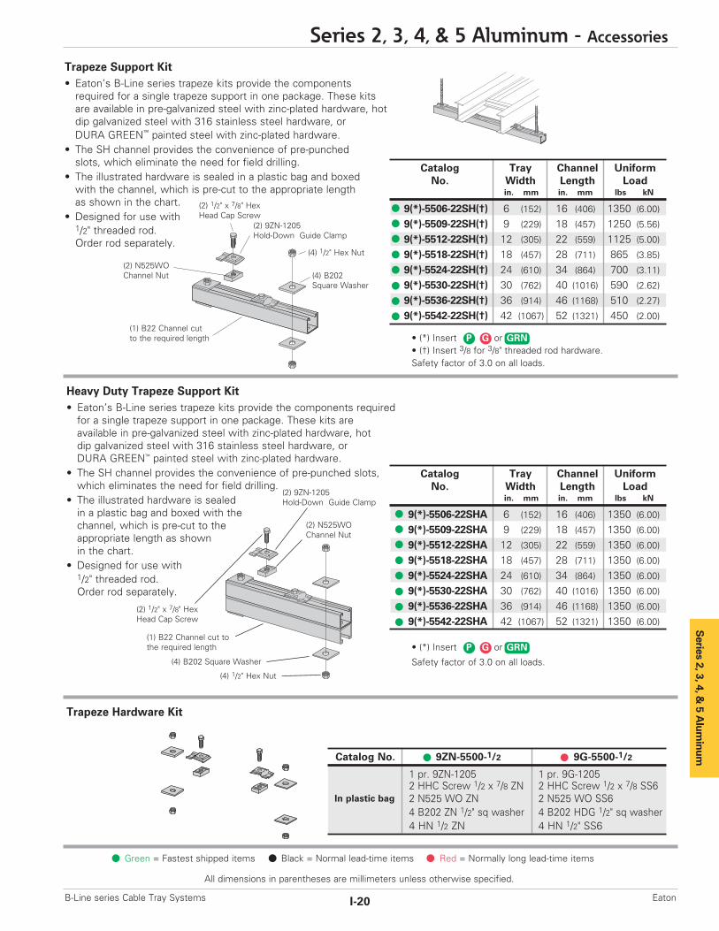
Catalog Tray Channel UniformNo. Width Length Load
in. mm in. mm lbs kN
9(*)-5506-22SH(†) 6 (152) 16 (406) 1350 (6.00)
9(*)-5509-22SH(†) 9 (229) 18 (457) 1250 (5.56)
9(*)-5512-22SH(†) 12 (305) 22 (559) 1125 (5.00)
9(*)-5518-22SH(†) 18 (457) 28 (711) 865 (3.85)
9(*)-5524-22SH(†) 24 (610) 34 (864) 700 (3.11)
9(*)-5530-22SH(†) 30 (762) 40 (1016) 590 (2.62)
9(*)-5536-22SH(†) 36 (914) 46 (1168) 510 (2.27)
9(*)-5542-22SH(†) 42 (1067) 52 (1321) 450 (2.00)(1) B22 Channel cutto the required length
(2) 9ZN-1205Hold-Down Guide Clamp
(4) B202Square Washer
(2) N525WOChannel Nut
(2) 1/2" x 7/8" HexHead Cap Screw
(4) 1/2" Hex Nut
Catalog No. 9ZN-5500-1/2 9G-5500-1/2
1 pr. 9ZN-1205 1 pr. 9G-12052 HHC Screw 1/2 x 7/8 ZN 2 HHC Screw 1/2 x 7/8 SS62 N525 WO ZN 2 N525 WO SS64 B202 ZN 1/2" sq washer 4 B202 HDG 1/2" sq washer4 HN 1/2 ZN 4 HN 1/2" SS6
In plastic bag
Catalog Tray Channel UniformNo. Width Length Load
in. mm in. mm lbs kN
9(*)-5506-22SHA 6 (152) 16 (406) 1350 (6.00)
9(*)-5509-22SHA 9 (229) 18 (457) 1350 (6.00)
9(*)-5512-22SHA 12 (305) 22 (559) 1350 (6.00)
9(*)-5518-22SHA 18 (457) 28 (711) 1350 (6.00)
9(*)-5524-22SHA 24 (610) 34 (864) 1350 (6.00)
9(*)-5530-22SHA 30 (762) 40 (1016) 1350 (6.00)
9(*)-5536-22SHA 36 (914) 46 (1168) 1350 (6.00)
9(*)-5542-22SHA 42 (1067) 52 (1321) 1350 (6.00)
Trapeze Hardware Kit
Heavy Duty Trapeze Support Kit• Eaton’s B-Line series trapeze kits provide the components required for a single trapeze support in one package. These kits are available in pre-galvanized steel with zinc-plated hardware, hot dip galvanized steel with 316 stainless steel hardware, orDURA GREEN™ painted steel with zinc-plated hardware.
• The SH channel provides the convenience of pre-punched slots,which eliminates the need for field drilling.
• The illustrated hardware is sealed in a plastic bag and boxed with thechannel, which is pre-cut to the appropriate length as shownin the chart.
• Designed for use with1/2" threaded rod. Order rod separately.
Trapeze Support Kit• Eaton’s B-Line series trapeze kits provide the componentsrequired for a single trapeze support in one package. These kits are available in pre-galvanized steel with zinc-plated hardware, hot dip galvanized steel with 316 stainless steel hardware, or DURA GREEN™ painted steel with zinc-plated hardware.
• The SH channel provides the convenience of pre-punchedslots, which eliminate the need for field drilling.
• The illustrated hardware is sealed in a plastic bag and boxedwith the channel, which is pre-cut to the appropriate lengthas shown in the chart.
• Designed for use with1/2" threaded rod. Order rod separately.
(2) 9ZN-1205Hold-Down Guide Clamp
(4) 1/2" Hex Nut
(2) 1/2" x 7/8" HexHead Cap Screw
(1) B22 Channel cut tothe required length
(4) B202 Square Washer
(2) N525WOChannel Nut
GRNGP
GRNGP
Catalog Tray ChannelNo. Width Length
in. (mm) in. (mm)
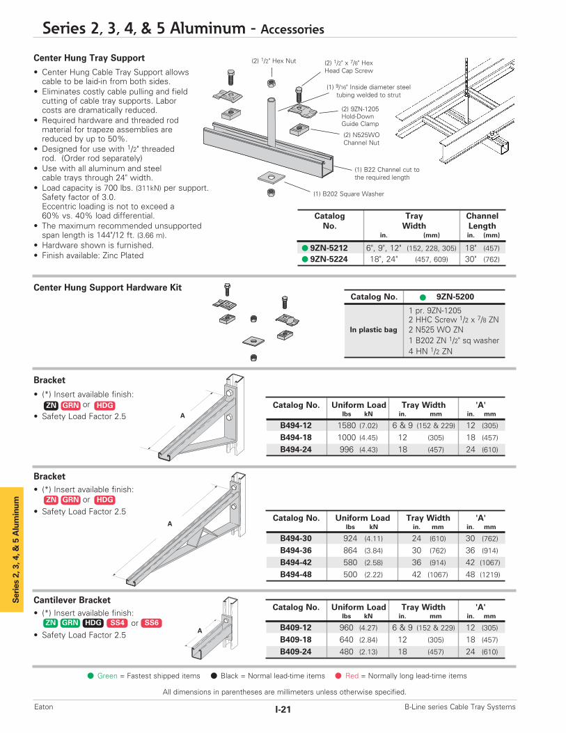
9ZN-5212 6", 9", 12" (152, 228, 305) 18" (457)9ZN-5224 18", 24" (457, 609) 30" (762)
Catalog No. Uniform Load Tray Width 'A'lbs kN in. mm in. mm
B494-30 924 (4.11) 24 (610) 30 (762)
B494-36 864 (3.84) 30 (762) 36 (914)
B494-42 580 (2.58) 36 (914) 42 (1067)
B494-48 500 (2.22) 42 (1067) 48 (1219)
(1) 9/16" Inside diameter steeltubing welded to strut
Catalog No. Uniform Load Tray Width 'A'lbs kN in. mm in. mm
B494-12 1580 (7.02) 6 & 9 (152 & 229) 12 (305)
B494-18 1000 (4.45) 12 (305) 18 (457)
B494-24 996 (4.43) 18 (457) 24 (610)
A
A
Series 2, 3, 4, & 5 Aluminum
Green = Fastest shipped items Black = Normal lead-time items Red = Normally long lead-time items
All dimensions in parentheses are millimeters unless otherwise specified.
Series 2, 3, 4, & 5 Aluminum - Accessories
I-21 B-Line series Cable Tray SystemsEaton
Center Hung Tray Support
• Center Hung Cable Tray Support allowscable to be laid-in from both sides.
• Eliminates costly cable pulling and fieldcutting of cable tray supports. Labor costs are dramatically reduced.
• Required hardware and threaded rodmaterial for trapeze assemblies arereduced by up to 50%.
• Designed for use with 1/2" threaded rod. (Order rod separately)
• Use with all aluminum and steel cable trays through 24" width.
• Load capacity is 700 lbs. (311kN) per support.Safety factor of 3.0.Eccentric loading is not to exceed a60% vs. 40% load differential.
• The maximum recommended unsupportedspan length is 144"/12 ft. (3.66 m).
• Hardware shown is furnished.• Finish available: Zinc Plated
Center Hung Support Hardware Kit
Bracket
• (*) Insert available finish:or
• Safety Load Factor 2.5
Bracket• (*) Insert available finish:
or• Safety Load Factor 2.5
Cantilever Bracket• (*) Insert available finish:
or• Safety Load Factor 2.5
ZN GRN HDG
Catalog No. 9ZN-5200
1 pr. 9ZN-12052 HHC Screw 1/2 x 7/8 ZN2 N525 WO ZN1 B202 ZN 1/2" sq washer4 HN 1/2 ZN
In plastic bag
(2) 9ZN-1205Hold-DownGuide Clamp
(2) 1/2" Hex Nut (2) 1/2" x 7/8" HexHead Cap Screw
(1) B22 Channel cut tothe required length
(1) B202 Square Washer
(2) N525WOChannel Nut
Catalog No. Uniform Load Tray Width 'A'lbs kN in. mm in. mm
B409-12 960 (4.27) 6 & 9 (152 & 229) 12 (305)
B409-18 640 (2.84) 12 (305) 18 (457)
B409-24 480 (2.13) 18 (457) 24 (610)
AZN GRN HDG SS4 SS6
ZN GRN HDG

A
A
71/2"(190mm)
A
Catalog No. Outside 'A'Cable Tray Ht. in. (mm)
9A-1224 4" 3.84 (97.54)
9A-1225 5" 4.73 (120.14)
9A-1226 6" 5.84 (148.34)
9A-1227 7" 6.84 (173.74)
U-Bolt Size Fits Pipe O.D.
B501-3/4 .841 - 1.050B501-1 1.051 - 1.315B501-11/4 1.316 - 1.660B501-11/2 1.661 - 1.900B501-2 1.901 - 2.375B501-21/2 2.376 - 2.875
Series 2, 3, 4, &
5 Alum
inum
Series 2, 3, 4, & 5 Aluminum - Accessories
I-22B-Line series Cable Tray Systems Eaton
All dimensions in parentheses are millimeters unless otherwise specified.
Green = Fastest shipped items Black = Normal lead-time items Red = Normally long lead-time items
Heavy Duty Hold Down Bracket• Design load is 2000 lbs (8.89kN) per pair.• Two bolt design.• Sold in pairs.• 3/8" cable tray attachment hardware provided.• 1/2" support attachment hardware not provided.• (*) Insert or• Recommended for support of vertical trays.
Cantilever Bracket• (*) Insert available finish:
or• Safety Load Factor 2.5
Catalog No. Uniform Load Tray Width 'A'lbs kN in. mm in. mm
B297-12 1660 (7.38) 6 & 9 (152 & 229) 12 (305)B297-18 1100 (4.89) 12 (305) 18 (457)B297-24 835 (3.71) 18 (457) 24 (610)B297-30 665 (2.93) 24 (610) 30 (762)B297-36 550 (2.44) 30 (762) 36 (914)B297-42 465 (2.06) 36 (914) 42 (1067)
ZN GRN HDG SS4
Underfloor Support (U-Bolts not included)• Finishes available: • Safety Load Factor 2.5
Catalog No. Uniform Load Tray Width 'A'lbs (kN) in. (mm) in. (mm)
B409UF-12 800 (3.56) 6 & 9 (152 & 229) 12 (305)
B409UF-21 450 (2.00) 12 & 18 (305 & 457) 21 (533)
ZN
Vertical Hanger Splice Plates• Design load is 1500 lbs (6.67kN) per pair.• Safety Factor of 2.5• Furnished in pairs.• Hole size: 9/16” (14mm) for
1/2” threaded rod.
ZN SS4 SS6 Catalog No.
9(*)-1241
Heavy Duty Hold Down Bracket• Design load is 4000 lbs (17.79kN) per pair.• Four bolt design.• Sold in pairs.• 3/8" cable tray attachment hardware provided• 1/2" support attachment hardware not provided.• (*) Insert or• Recommended for support of vertical trays.
ZN SS4 SS6
Catalog No.
9(*)-1242
Beam Clamp
• Finishes available: or• Sold in pieces.• Design load is 1200 lbs (5.34kN) per pair.• Safety Load Factor 5.0.• Order HHCS and Channel Nuts separately.
ZN GRN HDG SS4
Catalog No.
B355

Catalog No. Flange Widthin. (mm)
B312-6 Up to 6 (Up to 152)B312-9 6 - 9 (152 to 228)B312-12 9 - 12 (228 to 305)
Catalog 'A' 'TL' Wt./CNo. in. (mm ) in. (mm) lbs (kg)
B700-J4 81/2 (215.9) 5 (127.0) 44 (19.9)
B700-J6 111/2 (292.1) 6 (152.4) 53 (24.0)
B700-J9 121/4 (368.3) 6 (152.4) 63 (28.6)
B700-J12 171/2 (444.5) 6 (152.4) 78 (35.4)
Catalog Rod B C D E F T Design LoadNo. Size A in. (mm) in. (mm) in. (mm) in. (mm) in. (mm) lbs (kN)
B305 3/8"-16 3/8"-16 25/16 (58.7) 7/8 (22.2) 11/8 (28.6) 21/2 (63.5) 11 Ga. (3.0) 600 (2.67)
B306 3/8"-16 1/2"-13 27/16 (61.9) 7/8 (22.2) 11/8 (28.6) 21/2 (63.5) 7 Ga. (4.5) 1100 (4.90)
B307 1/2"-13 1/2"-13 27/16 (61.9) 7/8 (22.2) 11/8 (28.6) 21/2 (63.5) 7 Ga. (4.5) 1100 (4.90)
B308 1/2"-13 1/2"-13 29/16 (65.1) 7/8 (22.2) 11/8 (28.6) 21/2 (63.5) 1/4 (6.3) 1500 (6.68)
B321-1 3/8"-16 1/2"-13 39/16 (90.5) 111/16 (42.9) 15/8 (41.3) 31/4 (82.5) 1/4 (6.3) 1300 (5.79)
B321-2 1/2"-13 1/2"-13 39/16 (90.5) 111/16 (42.9) 15/8 (41.3) 31/4 (82.5) 1/4 (6.3) 1400 (6.23)
Catalog No. B212-1/4 B212-3/8
Design Load * 600 lbs. (2.67kN) 1000 lbs. (4.45 kN)Max. Flange Thick 3/4" (19 mm) 11/8" (28.6 mm)Mat'l. Thickness 1/4" (6.3 mm) 3/8" (9.5 mm)
B
ED
C
F T
A
A
Material: 7 Gauge (4.6)
1/2"-13 Rod & Hex Nut SoldSeparately
1/2"-13 Threads
11/2"(38.1)
‘A’
‘TL’Thread Length
17/8"(47.6)
J-Hook & Hex Nut Included
Catalog For Flange Width Wt./CNo. in. (mm) lbs (kg)
B750-J4 3 - 6 (76.2 - 152.4) 109 (49.4)
B750-J6 5 - 9 (127.0 - 288.6) 124 (56.2)
B750-J9 8 - 12 (203.2 - 304.8) 135 (61.,2)
B750-J12 11 - 15 (279.4 - 381.0) 147 (66.7)
Series 2, 3, 4, & 5 Aluminum
ZN HDG
ZN GRN HDG
ZN
ZN HDG
ZN
ZN
All dimensions in parentheses are millimeters unless otherwise specified.
Series 2, 3, 4, & 5 Aluminum - Accessories
I-23 B-Line series Cable Tray SystemsEaton
Catalog No. Design Load ‘A’lbs (kN) in. (mm)
B441-22 1200 (5.34) 33/8 (86)B441-22A 1200 (5.34) 5 (127)
Green = Fastest shipped items Black = Normal lead-time items Red = Normally long lead-time items
Beam Clamp
• Finishes available: or• Sold in pieces.• *Design load when used in pairs.Safety Load Factor 5.0
Anchor Strap - for B305 thru B308 & B321 Series
• Finish available:• For a maximum beam thickness of 3/4" (19mm).• For thicker beams, step up one flange width size.
Beam Clamp• Finish available: • Design Load 500 lbs. (2.22 kN)• Safety Load Factor 5.0• Recommended torque: 'J'-Hook Nut 125 In.-Lbs. (14.1 kN/m)
• Maximum flange thicknessof 3/4" (19mm).
B305 Thru B308 & B321 Series Beam Clamps• Finishes available: or• Setscrew included.• Safety Load Factor 5.0
Beam Clamp
• Finishes available: or• Sold in pieces.• *Design load when used in pairs.Safety Load Factor 5.0
‘J’-Hook• Finishes available: • Hex Nut included.

Aluminum Cover Part NumberingPrefix
Example: 80 7 A - 24 - 144
Cover Type Detail Material Tray Width Item Description80 = Solid 6 = Non-Flanged A = Aluminum 06 = 6" For Straight Section Cover:81 = Ventilated (80 & 81 type only) 09 = 9" 144 = 12 ft. (3.66 m)82 = Peaked 7 = Flange 12 = 12" 120 = 10 ft. (3.05 m)
18 = 18" 72 = 6 ft. (1.83 m)24 = 24" 60 = 5 ft. (1.52 m)30 = 30" For fitting covers: Insert suffix36 = 36" of fitting to be covered.
See example below.
Examples of Catalog Numbers for Fitting Covers:
A full range of covers is available for straight sections and fittings.
Solid covers should be used when maximum enclosure of the cable is desired and no accumulation of heat is expected. Ventilated covers provide an overhead cable shield, yet allow heat to escape.We recommend that covers be placed on vertical cable tray runs to a height of 6 ft. (1.83 m) to 8 ft. (2.44 m) above the floor to isolateboth cables and personnel. Flanged covers have a 1/2 in. (13 mm) flange. Cover clamps are not included with the cover and must beordered separately. All peaked covers are flanged. Standard peaked covers have 1/2" peak. Special purpose peaked covers, having a 2 to 3 pitch, provide additional slope and material thickness. The 2 to 3 pitch fitting covers are of multiple piece, welded construction.
Solid Flanged Ventilated Flanged Peaked Flanged 2 to 3 PitchPeaked Flanged(See page APP-4)
Vertical Bend CoverPrefix Suffix
80 7 A - 24 - 90 VO 24 - 4*Side Rail*Height RadiusFittingAngleWidthMaterialDetailCover Type
Solid Non-Flanged
Covers
Horizontal Bend CoverPrefix Suffix
80 7 A - 18 - 90 HB 24
RadiusFittingAngleWidthMaterialDetailCover Type
* Required for VO fittings only
Series 2, 3, 4, &
5 Alum
inum
Green = Fastest shipped items Black = Normal lead-time items Red = Normally long lead-time items
Series 2, 3, 4, & 5 Aluminum - Accessories
I-24B-Line series Cable Tray Systems Eaton
All dimensions in parentheses are millimeters unless otherwise specified.

Straight Section 60" or 72" ....................................... 4 pcs.Straight Section 120" or 144" ................................. 6 pcs.Horizontal/Vertical Bends .......................................... 4 pcs.Tees ........................................................................................... 6 pcs.Crosses ................................................................................... 8 pcs.
Peaked Cover Clamp
†
Series 2, 3, 4, & 5 Aluminum
TrefoilCableCleats
SingleCableCleats
All dimensions in parentheses are millimeters unless otherwise specified.
Series 2, 3, 4, & 5 Aluminum - Accessories
I-25 B-Line series Cable Tray SystemsEaton
Green = Fastest shipped items Black = Normal lead-time items Red = Normally long lead-time items
Standard Cover Clamp
• For indoor service only.• Setscrew included.• Sold per piece.
Combination Cover and Hold Down Clamp
• Sold per piece.• For indoor service only.
Raised Cover Clamp
• For indoor service only.• For use with flanged covers only.† Specify gap of 1", 2", 3" or 4".
Quantity of Standard Cover Clamps Required
Notes: When using the Heavy Duty Cover Clamp, only on-halfthe number of clamps stated above is required.Additional clamps may be necessary in extreme wind applications.
Cable Cleats(see pages O-1 thru O-5) Standard
Heavy Duty Cover Clamp
• Recommended for outdoor service.• (‡) Insert tray width† Add P to Catalog No.for peaked cover clamp.
Conduit to Cable Tray Adaptor
• Used to join covers• Plastic• (‡) Insert tray width
Tray Type Catalog No. Side Rail Height
Aluminum 9ZN-9012 All Sizes9A-9012
Tray Type Catalog No. Side Rail Height
Aluminum 9ZN-9112-† 4 & 5 Deep9ZN-9113-† 6 & 7 Deep
Tray Type Catalog No. Side Rail Heightin. (mm)
9A-9043 4 (101)
Aluminum 9A-9053 5 (127)
9A-9063 6 (152)
9A-9073 7 (78)
Catalog No.
99-9980-(‡)
Catalog No. Side Rail Heightin. mm
9A-(‡)-9044† 4 (101)9A-(‡)-9054† 5 (127)9A-(‡)-9064† 6 (152)9A-(‡)-9074† 7 (178)
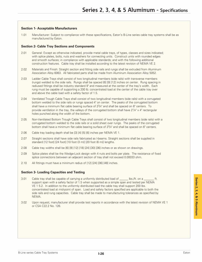
Section 1- Acceptable Manufacturers
1.01 Manufacturer: Subject to compliance with these specifications, Eaton’s B-Line series cable tray systems shall be as manufactured by Eaton.
Section 2- Cable Tray Sections and Components
2.01 General: Except as otherwise indicated, provide metal cable trays, of types, classes and sizes indicated;with splice plates, bolts, nuts and washers for connecting units. Construct units with rounded edgesand smooth surfaces; in compliance with applicable standards; and with the following additionalconstruction features. Cable tray shall be installed according to the latest revision of NEMA VE 2.
2.02 Materials and Finish: Straight section and fitting side rails and rungs shall be extruded from Aluminum Association Alloy 6063. All fabricated parts shall be made from Aluminum Association Alloy 5052.
2.03 Ladder Cable Trays shall consist of two longitudinal members (side rails) with transverse members(rungs) welded to the side rails. Rungs shall be spaced [6] [9] [12] inches on center. Rung spacing inradiused fittings shall be industry standard 9" and measured at the center of the tray’s width. Eachrung must be capable of supporting a 200 lb. concentrated load at the center of the cable tray overand above the cable load with a safety factor of 1.5.
2.04 Ventilated Trough Cable Trays shall consist of two longitudinal members (side rails) with a corrugated bottom welded to the side rails or rungs spaced 4" on center. The peaks of the corrugated bottomshall have a minimum flat cable bearing surface of 23/4" and shall be spaced on 6" centers. Toprovide ventilation in the tray, the valleys of the corrugated bottom shall have 21/4" x 4" rectangularholes punched along the width of the bottom.
2.05 Non-Ventilated Bottom Trough Cable Trays shall consist of two longitudinal members (side rails) with acorrugated bottom welded to the side rails or a solid sheet over rungs. The peaks of the corrugatedbottom shall have a minimum flat cable bearing surface of 23/4" and shall be spaced on 6" centers.
2.06 Cable tray loading depth shall be [3] [4] [5] [6] inches per NEMA VE 1.
2.07 Straight sections shall have side rails fabricated as I-beams. Straight sections shall be supplied instandard [12 foot] [24 foot] [10 foot (3 m)] [20 foot (6 m)] lengths.
2.08 Cable tray widths shall be [6] [9] [12] [18] [24] [30] [36] inches or as shown on drawings.
2.09 Splice plates shall be the Wedge-Lock design with 4 nuts and bolts per plate. The resistance of fixed splice connections between an adjacent section of tray shall not exceed 0.00033 ohm.
2.10 All fittings must have a minimum radius of [12] [24] [36] [48] inches.
Section 3- Loading Capacities and Testing
3.01 Cable tray shall be capable of carrying a uniformly distributed load of ______ lbs./ft. on a _______ ft. support span with a safety factor of 1.5 when supported as a simple span and tested per NEMAVE 1 5.2. In addition to the uniformly distributed load the cable tray shall support 200 lbs.concentrated load at mid-point of span. Load and safety factors specified are applicable to both theside rails and rung capacities. Cable tray shall be made to manufacturing tolerances as specified byNEMA.
3.02 Upon request, manufacturer shall provide test reports in accordance with the latest revision of NEMA VE 1or CSA C22.2 No. 126.
Series 2, 3, 4, &
5 Alum
inum
Series 2, 3, 4, & 5 Aluminum - Specifications
I-26B-Line series Cable Tray Systems Eaton

Series 2, 3, 4, & 5 Steel
Series 2, 3, 4, & 5 Steel - Straight Sections
J-1 B-Line series Cable Tray SystemsEaton
Series 2, 3, 4, &
5 Steel
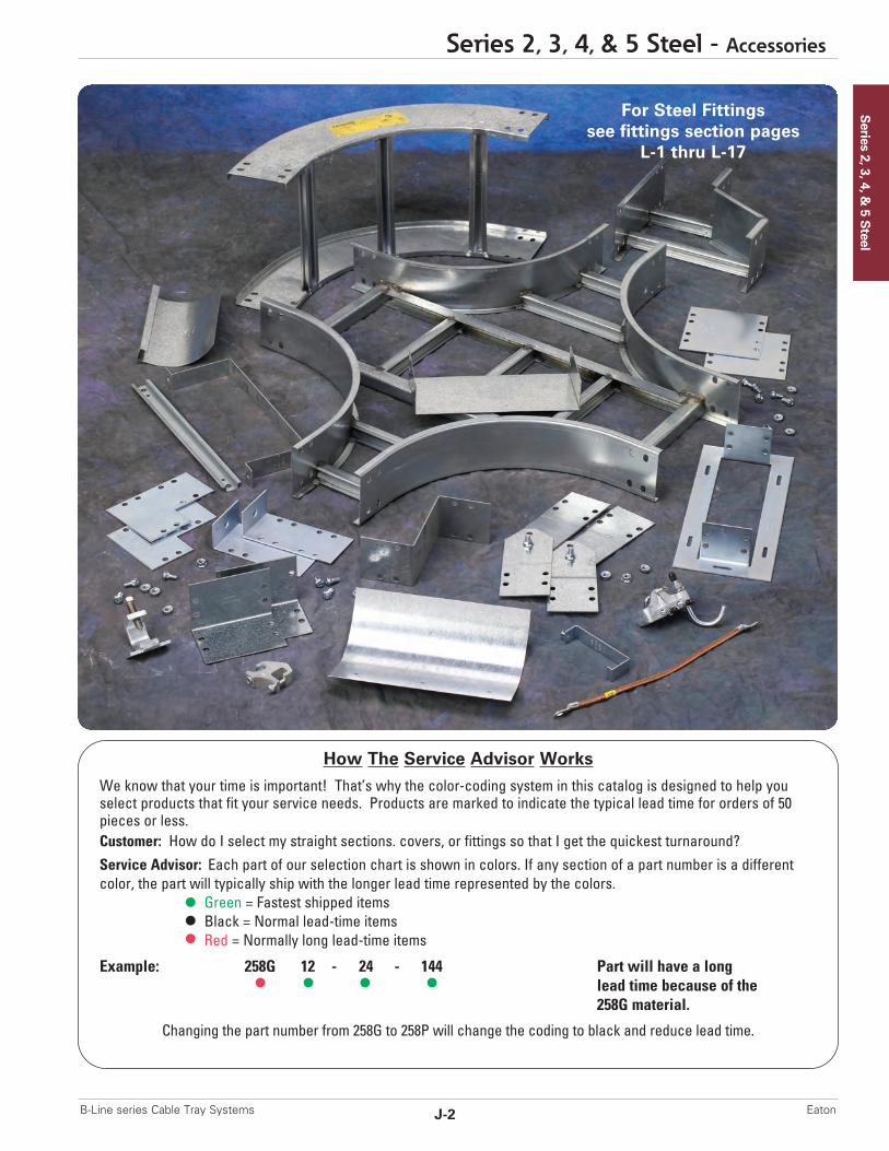
How The Service Advisor Works
We know that your time is important! That’s why the color-coding system in this catalog is designed to help youselect products that fit your service needs. Products are marked to indicate the typical lead time for orders of 50pieces or less.Customer: How do I select my straight sections. covers, or fittings so that I get the quickest turnaround?Service Advisor: Each part of our selection chart is shown in colors. If any section of a part number is a differentcolor, the part will typically ship with the longer lead time represented by the colors.
Green = Fastest shipped itemsBlack = Normal lead-time itemsRed = Normally long lead-time items
Example: 258G 12 - 24 - 144 Part will have a longlead time because of the 258G material.
Changing the part number from 258G to 258P will change the coding to black and reduce lead time.
For Steel Fittingssee fittings section pages
L-1 thru L-17
Series 2, 3, 4, & 5 Steel - Accessories
J-2B-Line series Cable Tray Systems Eaton
3" NEMA VE 1 Loading Depth4" Side Rail Height
Ladder Type(Specify Rung Spacing)
Ventilated Trough Non-Ventilated Trough
Series 2, 3, 4, & 5 Steel
Green = Fastest shipped items Black = Normal lead-time items Red = Normally long lead-time items
All dimensions in parentheses are millimeters unless otherwise specified.
Series 2, 3, 4, & 5 Steel - Straight Sections
J-3 B-Line series Cable Tray SystemsEaton
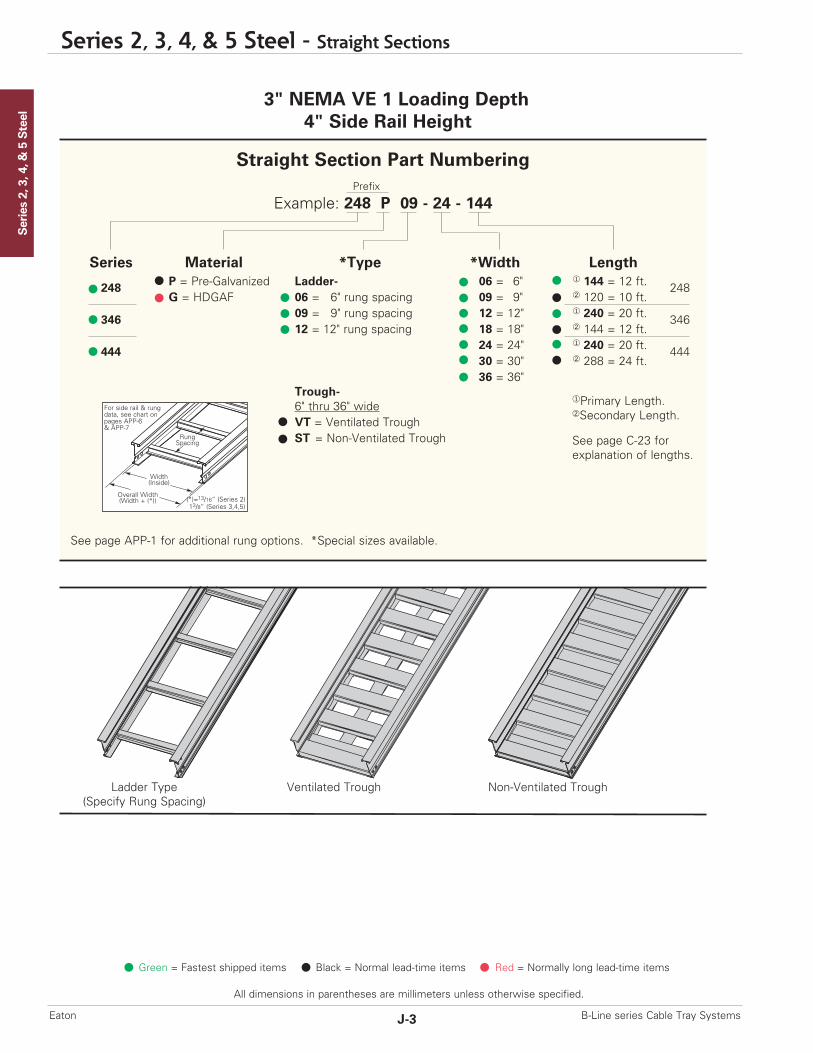
Straight Section Part NumberingPrefix
Example: 248 P 09 - 24 - 144
Series Material *Type *Width Length
248 P = Pre-Galvanized Ladder- 06 = 6" ¨ 144 = 12 ft. 248G = HDGAF 06 = 6" rung spacing 09 = 9" ¡ 120 = 10 ft.
346 09 = 9" rung spacing 12 = 12" ¨ 240 = 20 ft. 34612 = 12" rung spacing 18 = 18" ¡ 144 = 12 ft.
444 24 = 24" ¨ 240 = 20 ft. 44430 = 30" ¡ 288 = 24 ft. 36 = 36"
Trough-6" thru 36" wideVT = Ventilated TroughST = Non-Ventilated Trough
See page APP-1 for additional rung options. *Special sizes available.
¨Primary Length.¡Secondary Length.
See page C-23 for explanation of lengths.
RungSpacing
Width(Inside)
Overall Width(Width + (*))
For side rail & rungdata, see chart onpages APP-6 & APP-7
(*)=13/16” (Series 2)13/8” (Series 3,4,5)
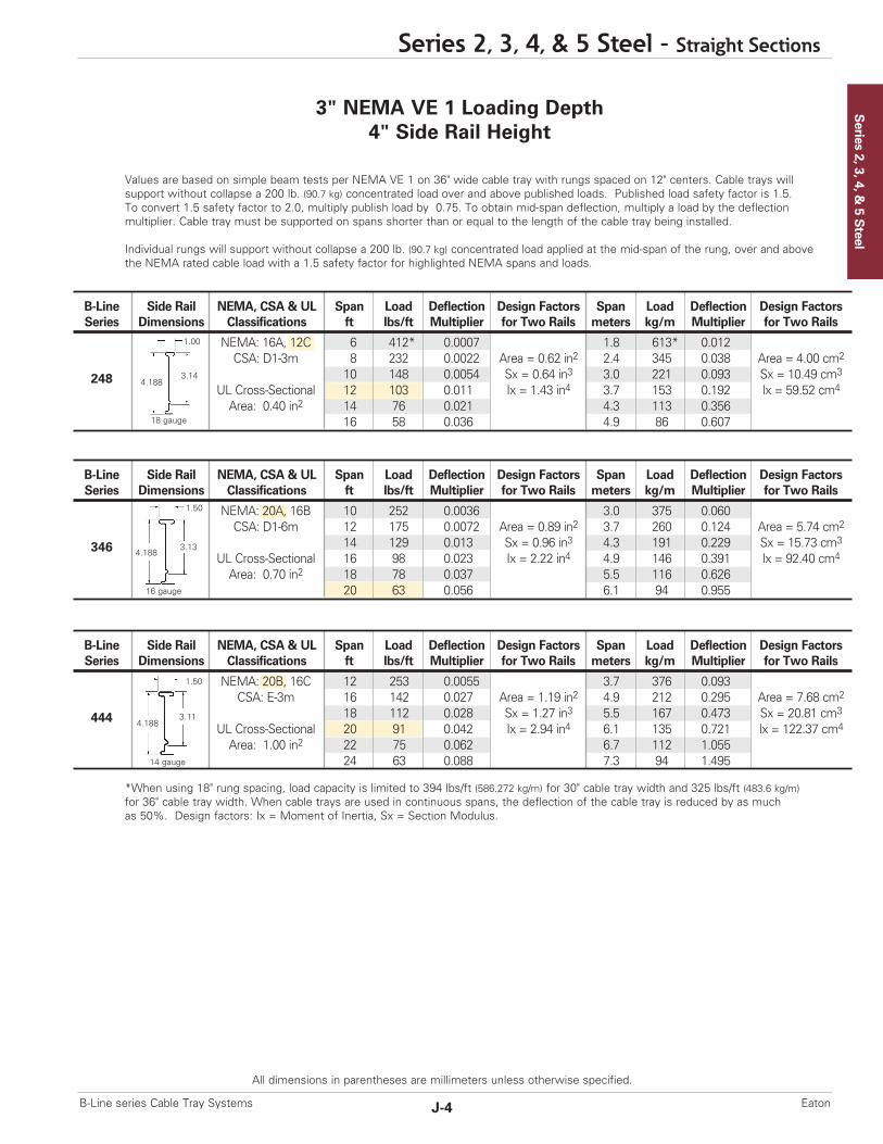
Values are based on simple beam tests per NEMA VE 1 on 36" wide cable tray with rungs spaced on 12" centers. Cable trays willsupport without collapse a 200 lb. (90.7 kg) concentrated load over and above published loads. Published load safety factor is 1.5. To convert 1.5 safety factor to 2.0, multiply publish load by 0.75. To obtain mid-span deflection, multiply a load by the deflection multiplier. Cable tray must be supported on spans shorter than or equal to the length of the cable tray being installed.
Individual rungs will support without collapse a 200 lb. (90.7 kg) concentrated load applied at the mid-span of the rung, over and abovethe NEMA rated cable load with a 1.5 safety factor for highlighted NEMA spans and loads.
*When using 18" rung spacing, load capacity is limited to 394 lbs/ft (586.272 kg/m) for 30" cable tray width and 325 lbs/ft (483.6 kg/m)for 36" cable tray width. When cable trays are used in continuous spans, the deflection of the cable tray is reduced by as muchas 50%. Design factors: Ix = Moment of Inertia, Sx = Section Modulus.
3" NEMA VE 1 Loading Depth4" Side Rail Height
Series 2, 3, 4, &
5 Steel
Series 2, 3, 4, & 5 Steel - Straight Sections
J-4B-Line series Cable Tray Systems Eaton
All dimensions in parentheses are millimeters unless otherwise specified.
B-Line Side Rail NEMA, CSA & UL Span Load Deflection Design Factors Span Load Deflection Design FactorsSeries Dimensions Classifications ft lbs/ft Multiplier for Two Rails meters kg/m Multiplier for Two Rails
NEMA: 16A, 12C 6 412* 0.0007 1.8 613* 0.012CSA: D1-3m 8 232 0.0022 Area = 0.62 in2 2.4 345 0.038 Area = 4.00 cm2
10 148 0.0054 Sx = 0.64 in3 3.0 221 0.093 Sx = 10.49 cm3
UL Cross-Sectional 12 103 0.011 Ix = 1.43 in4 3.7 153 0.192 Ix = 59.52 cm4
Area: 0.40 in2 14 76 0.021 4.3 113 0.35616 58 0.036 4.9 86 0.607
248
B-Line Side Rail NEMA, CSA & UL Span Load Deflection Design Factors Span Load Deflection Design FactorsSeries Dimensions Classifications ft lbs/ft Multiplier for Two Rails meters kg/m Multiplier for Two Rails
NEMA: 20A, 16B 10 252 0.0036 3.0 375 0.060CSA: D1-6m 12 175 0.0072 Area = 0.89 in2 3.7 260 0.124 Area = 5.74 cm2
14 129 0.013 Sx = 0.96 in3 4.3 191 0.229 Sx = 15.73 cm3
UL Cross-Sectional 16 98 0.023 Ix = 2.22 in4 4.9 146 0.391 Ix = 92.40 cm4
Area: 0.70 in2 18 78 0.037 5.5 116 0.62620 63 0.056 6.1 94 0.955
346
B-Line Side Rail NEMA, CSA & UL Span Load Deflection Design Factors Span Load Deflection Design FactorsSeries Dimensions Classifications ft lbs/ft Multiplier for Two Rails meters kg/m Multiplier for Two Rails
NEMA: 20B, 16C 12 253 0.0055 3.7 376 0.093CSA: E-3m 16 142 0.027 Area = 1.19 in2 4.9 212 0.295 Area = 7.68 cm2
18 112 0.028 Sx = 1.27 in3 5.5 167 0.473 Sx = 20.81 cm3
UL Cross-Sectional 20 91 0.042 Ix = 2.94 in4 6.1 135 0.721 Ix = 122.37 cm4
Area: 1.00 in2 22 75 0.062 6.7 112 1.05524 63 0.088 7.3 94 1.495
444
1.00
4.188
18 gauge
3.14
1.50
4.1883.13
1.50
4.1883.11
16 gauge
14 gauge

4" NEMA VE 1 Loading Depth5" Side Rail Height
Series 2, 3, 4, & 5 Steel
Green = Fastest shipped items Black = Normal lead-time items Red = Normally long lead-time items
All dimensions in parentheses are millimeters unless otherwise specified.
Series 2, 3, 4, & 5 Steel - Straight Sections
J-5 B-Line series Cable Tray SystemsEaton
Ladder Type(Specify Rung Spacing)
Ventilated Trough Non-Ventilated Trough
Straight Section Part NumberingPrefix
Example: 258 P 09 - 24 - 144
Series Material *Type *Width Length
258 P = Pre-Galvanized Ladder- 06 = 6" ¨ 144 = 12 ft. 258G = HDGAF 06 = 6" rung spacing 09 = 9" ¡ 120 = 10 ft.
356 09 = 9" rung spacing 12 = 12" ¨ 240 = 20 ft. 35612 = 12" rung spacing 18 = 18" ¡ 144 = 12 ft.
454 24 = 24" ¨ 240 = 20 ft. 45430 = 30" ¡ 288 = 24 ft. 36 = 36"
Trough-6" thru 36" wideVT = Ventilated TroughST = Non-Ventilated Trough
See page APP-1 for additional rung options. *Special sizes available.
¨Primary Length.¡Secondary Length.
See page C-23 for explanation of lengths.
RungSpacing
Width(Inside)
Overall Width(Width + (*))
For side rail & rungdata, see chart onpages APP-6& APP-7
(*)=13/16” (Series 2)13/8” (Series 3,4,5)

Values are based on simple beam tests per NEMA VE 1 on 36" wide cable tray with rungs spaced on 12" centers. Cable trays willsupport without collapse a 200 lb. (90.7 kg) concentrated load over and above published loads. Published load safety factor is 1.5. To convert 1.5 safety factor to 2.0, multiply publish load by 0.75. To obtain mid-span deflection, multiply a load by the deflection multiplier. Cable tray must be supported on spans shorter than or equal to the length of the cable tray being installed.
Individual rungs will support without collapse a 200 lb. (90.7 kg) concentrated load applied at the mid-span of the rung, over and abovethe NEMA rated cable load with a 1.5 safety factor for highlighted NEMA spans and loads.
*When using 18" rung spacing, load capacity is limited to 394 lbs/ft (586.272 kg/m) for 30" cable tray width and 325 lbs/ft (483.6 kg/m)for 36" cable tray width. When cable trays are used in continuous spans, the deflection of the cable tray is reduced by as much as50%. Design factors: Ix = Moment of Inertia, Sx = Section Modulus.
4" NEMA VE 1 Loading Depth5" Side Rail Height
Series 2, 3, 4, &
5 Steel
Series 2, 3, 4, & 5 Steel - Straight Sections
J-6B-Line series Cable Tray Systems Eaton
All dimensions in parentheses are millimeters unless otherwise specified.
B-Line Side Rail NEMA, CSA & UL Span Load Deflection Design Factors Span Load Deflection Design FactorsSeries Dimensions Classifications ft lbs/ft Multiplier for Two Rails meters kg/m Multiplier for Two Rails
NEMA: 16A, 12C 6 436* 0.0004 1.8 649* 0.007CSA: D1-3m 8 245 0.0013 Area = 0.71 in2 2.4 365 0.022 Area = 4.58 cm2
10 157 0.0032 Sx = 0.89 in3 3.0 234 0.054 Sx = 14.58 cm3
UL Cross-Sectional 12 109 0.0066 Ix = 2.44 in4 3.7 162 0.113 Ix = 101.56 cm4
Area: 0.40 in2 14 80 0.012 4.3 119 0.20916 61 0.021 4.9 91 0.356
258
B-Line Side Rail NEMA, CSA & UL Span Load Deflection Design Factors Span Load Deflection Design FactorsSeries Dimensions Classifications ft lbs/ft Multiplier for Two Rails meters kg/m Multiplier for Two Rails
NEMA: 20A, 16C 10 276 0.0021 3.0 411 0.036CSA: D1-6m 12 192 0.0043 Area = 1.00 in2 3.7 285 0.074 Area = 6.45 cm2
14 141 0.0080 Sx = 1.31 in3 4.3 210 0.136 Sx = 21.47 cm3
UL Cross-Sectional 16 108 0.014 Ix = 3.73 in4 4.9 160 0.233 Ix = 155.25 cm4
Area: 0.70 in2 18 85 0.022 5.5 127 0.37320 69 0.033 6.1 103 0.568
356
B-Line Side Rail NEMA, CSA & UL Span Load Deflection Design Factors Span Load Deflection Design FactorsSeries Dimensions Classifications ft lbs/ft Multiplier for Two Rails meters kg/m Multiplier for Two Rails
NEMA: 20C 12 294 0.0032 3.7 438 0.055CSA: E-6m 16 166 0.010 Area = 1.34 in2 4.9 246 0.175 Area = 8.65 cm2
18 131 0.016 Sx = 1.75 in3 5.5 195 0.280 Sx = 28.68 cm3
UL Cross-Sectional 20 106 0.026 Ix = 4.96 in4 6.1 158 0.427 Ix = 206.45 cm4
Area: 1.00 in2 22 88 0.037 6.7 130 0.62524 74 0.052 7.3 110 0.886
454
1.00
5.1884.14
1.50
5.188 4.13
1.50
5.1884.11
18 gauge
14 gauge
16 gauge
5" NEMA VE 1 Loading Depth6" Side Rail Height
Series 2, 3, 4, & 5 Steel
Green = Fastest shipped items Black = Normal lead-time items Red = Normally long lead-time items
All dimensions in parentheses are millimeters unless otherwise specified.
Series 2, 3, 4, & 5 Steel - Straight Sections
J-7 B-Line series Cable Tray SystemsEaton
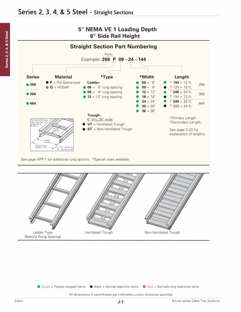
Ladder Type(Specify Rung Spacing)
Ventilated Trough Non-Ventilated Trough
Straight Section Part NumberingPrefix
Example: 268 P 09 - 24 - 144
Series Material *Type *Width Length
268 P = Pre-Galvanized Ladder- 06 = 6" ¨ 144 = 12 ft. 268G = HDGAF 06 = 6" rung spacing 09 = 9" ¡ 120 = 10 ft.
366 09 = 9" rung spacing 12 = 12" ¨ 240 = 20 ft. 36612 = 12" rung spacing 18 = 18" ¡ 144 = 12 ft.
464 24 = 24" ¨ 240 = 20 ft. 46430 = 30" ¡ 288 = 24 ft. 36 = 36"
Trough-6" thru 36" wideVT = Ventilated TroughST = Non-Ventilated Trough
See page APP-1 for additional rung options. *Special sizes available.
¨Primary Length.¡Secondary Length.
See page C-23 for explanation of lengths.
RungSpacing
Width(Inside)
Overall Width(Width + (*))
For side rail & rungdata, see chart onpages AP-6& APP-7
(*)=13/16” (Series 2)13/8” (Series 3,4,5)

1.00
6.1885.14
1.50
6.188 5.14
18 gauge
16 gauge
5" NEMA VE 1 Loading Depth6" Side Rail Height
Series 2, 3, 4, &
5 Steel
Series 2, 3, 4, & 5 Steel - Straight Sections
J-8B-Line series Cable Tray Systems Eaton
All dimensions in parentheses are millimeters unless otherwise specified.
Values are based on simple beam tests per NEMA VE 1 on 36" wide cable tray with rungs spaced on 12" centers. Cable trays willsupport without collapse a 200 lb. (90.7 kg) concentrated load over and above published loads. Published load safety factor is 1.5. To convert 1.5 safety factor to 2.0, multiply publish load by 0.75. To obtain mid-span deflection, multiply a load by the deflection multiplier. Cable tray must be supported on spans shorter than or equal to the length of the cable tray being installed.
Individual rungs will support without collapse a 200 lb. (90.7 kg) concentrated load applied at the mid-span of the rung, over and abovethe NEMA rated cable load with a 1.5 safety factor for highlighted NEMA spans and loads.
*When using 18" rung spacing, load capacity is limited to 394 lbs/ft (586.272 kg/m) for 30" cable tray width and 325 lbs/ft (483.6 kg/m)for 36" cable tray width. When cable trays are used in continuous spans, the deflection of the cable tray is reduced by as much as50%. Design factors: Ix = Moment of Inertia, Sx = Section Modulus.
B-Line Side Rail NEMA, CSA & UL Span Load Deflection Design Factors Span Load Deflection Design FactorsSeries Dimensions Classifications ft lbs/ft Multiplier for Two Rails meters kg/m Multiplier for Two Rails
NEMA: 16A, 12C 6 440* 0.0003 1.8 655* 0.005CSA: D1-3m 8 248 0.0008 Area = 0.80 in2 2.4 368 0.014 Area = 5.16 cm2
10 158 0.0020 Sx = 1.18 in3 3.0 236 0.035 Sx = 19.34 cm3
UL Cross-Sectional 12 110 0.0042 Ix = 3.81 in4 3.7 164 0.072 Ix = 158.58 cm4
Area: 0.70 in2 14 81 0.0078 4.3 120 0.13416 62 0.013 4.9 92 0.228
268
B-Line Side Rail NEMA, CSA & UL Span Load Deflection Design Factors Span Load Deflection Design FactorsSeries Dimensions Classifications ft lbs/ft Multiplier for Two Rails meters kg/m Multiplier for Two Rails
NEMA: 20B, 16C 10 300 0.0014 3.0 446 0.023CSA: E-6m 12 208 0.0028 Area = 1.11 in2 3.7 310 0.048 Area = 7.16 cm2
14 153 0.0052 Sx = 1.71 in3 4.3 228 0.089 Sx = 28.02 cm3
UL Cross-Sectional 16 117 0.0089 Ix = 5.74 in4 4.9 174 0.151 Ix = 238.92 cm4
Area: 1.00 in2 18 93 0.014 5.5 138 0.24220 75 0.022 6.1 112 0.369
366
B-Line Side Rail NEMA, CSA & UL Span Load Deflection Design Factors Span Load Deflection Design FactorsSeries Dimensions Classifications ft lbs/ft Multiplier for Two Rails meters kg/m Multiplier for Two Rails
NEMA: 20C 12 342* 0.002 3.7 508* 0.035CSA: E-6m 16 192 0.007 Area = 1.49 in2 4.9 286 0.113 Area = 9.61 cm2
18 152 0.011 Sx = 2.27 in3 5.5 226 0.182 Sx = 37.36 cm3
UL Cross-Sectional 20 123 0.016 Ix = 7.65 in4 6.1 183 0.277 Ix = 318.42 cm4
Area: 1.00 in2 22 102 0.024 6.7 151 0.40624 85 0.034 7.3 127 0.574
464
1.50
6.1885.11
14 gauge

6" NEMA VE 1 Loading Depth7" Side Rail Height
Series 2, 3, 4, & 5 Steel
Green = Fastest shipped items Black = Normal lead-time items Red = Normally long lead-time items
All dimensions in parentheses are millimeters unless otherwise specified.
Series 2, 3, 4, & 5 Steel - Straight Sections
J-9 B-Line series Cable Tray SystemsEaton
Ladder Type(Specify Rung Spacing)
Ventilated Trough Non-Ventilated Trough
Straight Section Part NumberingPrefix
Example: 378 P 09 - 24 - 144
Series Material *Type *Width Length
378 P = Pre-Galvanized Ladder- 06 = 6" ¨ 144 = 12 ft. 378G = HDGAF 06 = 6" rung spacing 09 = 9" ¡ 120 = 10 ft.
476 09 = 9" rung spacing 12 = 12" ¨ 240 = 20 ft. 47612 = 12" rung spacing 18 = 18" ¡ 288 = 24 ft.
574 24 = 24" ¨ 240 = 20 ft. 57430 = 30" ¡ 288 = 24 ft. 36 = 36"
Trough-6" thru 36" wideVT = Ventilated TroughST = Non-Ventilated Trough
See page APP-1 for additional rung options. *Special sizes available.
¨Primary Length.¡Secondary Length.
See page C-23 for explanation of lengths.
RungSpacing
Width(Inside)
Overall Width(Width + (*))
For side rail & rungdata, see chart onpages AP-6& APP-7
(*)=13/16” (Series 2)13/8” (Series 3,4,5)

When cable trays are used in continuous spans, the deflection of the cable tray is reduced by as much as 50%. Design factors: Ix = Moment of Inertia, Sx = Section Modulus.
6" NEMA VE 1 Loading Depth7" Side Rail Height
Series 2, 3, 4, &
5 Steel
Series 2, 3, 4, & 5 Steel - Straight Sections
J-10B-Line series Cable Tray Systems Eaton
All dimensions in parentheses are millimeters unless otherwise specified.
Values are based on simple beam tests per NEMA VE 1 on 36" wide cable tray with rungs spaced on 12" centers. Cable trays willsupport without collapse a 200 lb. (90.7 kg) concentrated load over and above published loads. Published load safety factor is 1.5. To convert 1.5 safety factor to 2.0, multiply publish load by 0.75. To obtain mid-span deflection, multiply a load by the deflection multiplier. Cable tray must be supported on spans shorter than or equal to the length of the cable tray being installed.
Individual rungs will support without collapse a 200 lb. (90.7 kg) concentrated load applied at the mid-span of the rung, over and abovethe NEMA rated cable load with a 1.5 safety factor for highlighted NEMA spans and loads.
B-Line Side Rail NEMA, CSA & UL Span Load Deflection Design Factors Span Load Deflection Design FactorsSeries Dimensions Classifications ft lbs/ft Multiplier for Two Rails meters kg/m Multiplier for Two Rails
8 319 0.0006 2.4 474 0.009NEMA: 20A, 16B 10 204 0.0014 3.0 304 0.023CSA: D1-3m 12 142 0.0028 Area = 1.01 in2 3.7 211 0.048 Area = 6.52 cm2
14 104 0.0052 Sx = 1.77 in3 4.3 155 0.089 Sx = 29.01 cm3
UL Cross-Sectional 16 80 0.0089 Ix = 6.90 in4 4.9 119 0.151 Ix = 287.20 cm4
Area: 0.70 in2 18 63 0.014 5.5 94 0.24220 51 0.022 6.1 76 0.369
378
B-Line Side Rail NEMA, CSA & UL Span Load Deflection Design Factors Span Load Deflection Design FactorsSeries Dimensions Classifications ft lbs/ft Multiplier for Two Rails meters kg/m Multiplier for Two Rails
NEMA: 20B, 16C 12 214 0.0019 3.7 318 0.033CSA: D1-6m 16 129 0.0061 Area = 1.22 in2 4.9 179 0.105 Area = 7.87 cm2
18 95 0.010 Sx = 2.14 in3 5.5 141 0.168 Sx = 35.07 cm3
UL Cross-Sectional 20 77 0.015 Ix = 8.30 in4 6.1 115 0.255 Ix = 345.47 cm4
Area: 1.00 in2 22 64 0.022 6.7 95 0.37424 53 0.031 7.3 80 0.529
476
B-Line Side Rail NEMA, CSA & UL Span Load Deflection Design Factors Span Load Deflection Design FactorsSeries Dimensions Classifications ft lbs/ft Multiplier for Two Rails meters kg/m Multiplier for Two Rails
NEMA: 20C 12 361 0.0014 3.7 537 0.025CSA: E-6m 16 203 0.0046 Area = 1.64 in2 4.9 302 0.078 Area = 10.58 cm2
18 160 0.0073 Sx = 2.87 in3 5.5 239 0.125 Sx = 47.03 cm3
UL Cross-Sectional 20 130 0.011 Ix = 11.10 in4 6.1 193 0.191 Ix = 462.02 cm4
Area: 1.50 in2 22 107 0.016 6.7 160 0.28024 90 0.023 7.3 134 0.396
574
7.188
1.50
7.1886.14
1.50
6.13
1.50
7.1886.11
18 gauge
16 gauge
14 gauge
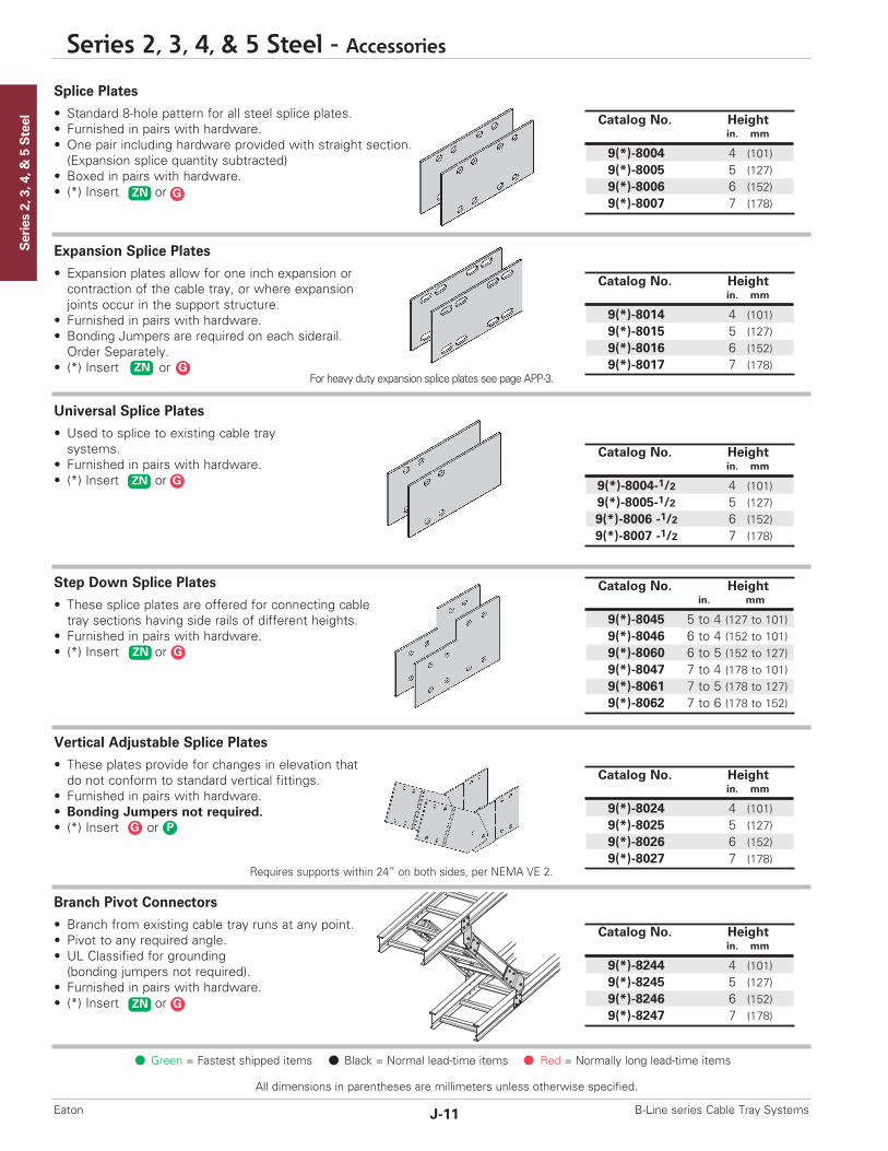
Series 2, 3, 4, & 5 Steel
ZN G
All dimensions in parentheses are millimeters unless otherwise specified.
Series 2, 3, 4, & 5 Steel - Accessories
J-11 B-Line series Cable Tray SystemsEaton
Catalog No. Heightin. mm
9(*)-8004 4 (101)9(*)-8005 5 (127)9(*)-8006 6 (152)9(*)-8007 7 (178)
Catalog No. Heightin. mm
9(*)-8014 4 (101)9(*)-8015 5 (127)9(*)-8016 6 (152)9(*)-8017 7 (178)
Catalog No. Heightin. mm
9(*)-8004-1/2 4 (101)9(*)-8005-1/2 5 (127)9(*)-8006 -1/2 6 (152)9(*)-8007 -1/2 7 (178)
Catalog No. Heightin. mm
9(*)-8045 5 to 4 (127 to 101)9(*)-8046 6 to 4 (152 to 101)9(*)-8060 6 to 5 (152 to 127)9(*)-8047 7 to 4 (178 to 101)9(*)-8061 7 to 5 (178 to 127)9(*)-8062 7 to 6 (178 to 152)
Catalog No. Heightin. mm
9(*)-8244 4 (101)9(*)-8245 5 (127)9(*)-8246 6 (152)9(*)-8247 7 (178)
Catalog No. Heightin. mm
9(*)-8024 4 (101)9(*)-8025 5 (127)9(*)-8026 6 (152)9(*)-8027 7 (178)
Requires supports within 24” on both sides, per NEMA VE 2.
Green = Fastest shipped items Black = Normal lead-time items Red = Normally long lead-time items
Splice Plates
• Standard 8-hole pattern for all steel splice plates. • Furnished in pairs with hardware.• One pair including hardware provided with straight section.(Expansion splice quantity subtracted)
• Boxed in pairs with hardware.• (*) Insert or
Universal Splice Plates
• Used to splice to existing cable traysystems.
• Furnished in pairs with hardware.• (*) Insert or
Step Down Splice Plates
• These splice plates are offered for connecting cabletray sections having side rails of different heights.
• Furnished in pairs with hardware.• (*) Insert or
Vertical Adjustable Splice Plates
• These plates provide for changes in elevation thatdo not conform to standard vertical fittings.
• Furnished in pairs with hardware.• Bonding Jumpers not required.• (*) Insert or
Expansion Splice Plates
• Expansion plates allow for one inch expansion orcontraction of the cable tray, or where expansionjoints occur in the support structure.
• Furnished in pairs with hardware.• Bonding Jumpers are required on each siderail.Order Separately.
• (*) Insert or
Branch Pivot Connectors
• Branch from existing cable tray runs at any point.• Pivot to any required angle.• UL Classified for grounding (bonding jumpers not required).
• Furnished in pairs with hardware.• (*) Insert or
ZN G
For heavy duty expansion splice plates see page APP-3.
ZN G
ZN G
ZN G
G P
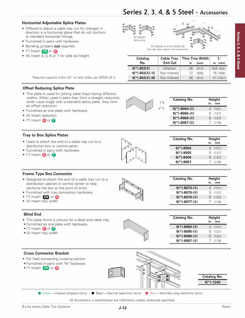
Series 2, 3, 4, &
5 Steel
Series 2, 3, 4, & 5 Steel - Accessories
J-12B-Line series Cable Tray Systems Eaton
All dimensions in parentheses are millimeters unless otherwise specified.
LL
ZN G
Green = Fastest shipped items Black = Normal lead-time items Red = Normally long lead-time items
Tray to Box Splice Plates
• Used to attach the end of a cable tray run to adistribution box or control panel.
• Furnished in pairs with hardware.• (*) Insert or
Blind End• This plate forms a closure for a dead end cable tray.• Furnished as one plate with hardware.• (*) Insert or• (‡) Insert tray width
Cross Connector Bracket• For field connecting crossing section.• Furnished in pairs with 3/8" hardware.• (*) Insert or
Frame Type Box Connector• Designed to attach the end of a cable tray run to adistribution cabinet or control center to help reinforce the box at the point of entry.
• Furnished with tray connection hardware.• (*) Insert or• (‡) Insert tray width
Horizontal Adjustable Splice Plates• Offered to adjust a cable tray run for changes indirection in a horizontal plane that do not conform to standard horizontal fittings.
• Furnished in pairs with hardware.• Bonding jumpers not required.• (*) Insert or• (X) Insert 4, 5, 6 or 7 for side rail height.
Offset Reducing Splice Plate• This plate is used for joining cable trays having differentwidths. When used in pairs they form a straight reduction;when used singly with a standard splice plate, they forman offset reduction.
• Furnished as one plate with hardware.• (‡) Insert reduction• (*) Insert or
Catalog Cable Tray Thru Tray Width ‘L’No. End Cut in. (mm) in. (mm)
9(*)-803(X) Mitered 36 (914) N/A (NA)9(*)-803(X)-12 Not mitered 12 (305) 16 (406)9(*)-803(X)-36 Not mitered 36 (914) 41 (1041)
9(*)-803(X)Splice only
9(*)-803(X)-12 or 9(*)-803(X)-36One pair splice plates with extensions.
Requires supports within 24” on both sides, per NEMA VE 2.
Catalog No. Heightin. mm
9(*)-8064-(‡) 4 (101)9(*)-8065-(‡) 5 (127)9(*)-8066-(‡) 6 (152)9(*)-8067-(‡) 7 (178)
Catalog No. Heightin. mm
9(*)-8054 4 (101)9(*)-8055 5 (127)9(*)-8056 6 (152)9(*)-8057 7 (178)
Catalog No. Heightin. mm
9(*)-8084-(‡) 4 (101)9(*)-8085-(‡) 5 (127)9(*)-8086-(‡) 6 (152)9(*)-8087-(‡) 7 (178)
Catalog No. Heightin. mm
9(*)-8074-(‡) 4 (101)9(*)-8075-(‡) 5 (127)9(*)-8076-(‡) 6 (152)9(*)-8077-(‡) 7 (178)
G P
ZN G
Catalog No.
9(*)-1240
G P
ZN G
G P
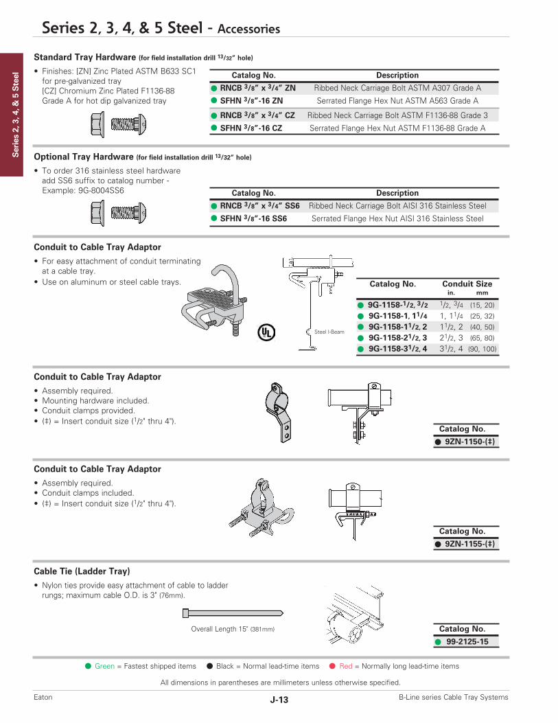
Series 2, 3, 4, & 5 Steel
All dimensions in parentheses are millimeters unless otherwise specified.
Series 2, 3, 4, & 5 Steel - Accessories
J-13 B-Line series Cable Tray SystemsEaton
Catalog No.
9ZN-1150-(‡)
Catalog No.
9ZN-1155-(‡)
Catalog No.
99-2125-15
Catalog No. Conduit Sizein. mm
9G-1158-1/2, 3/2 1/2, 3/4 (15, 20)9G-1158-1, 11/4 1, 11/4 (25, 32)9G-1158-11/2, 2 11/2, 2 (40, 50)9G-1158-21/2, 3 21/2, 3 (65, 80)9G-1158-31/2, 4 31/2, 4 (90, 100)
Green = Fastest shipped items Black = Normal lead-time items Red = Normally long lead-time items
Standard Tray Hardware (for field installation drill 13/32” hole)
• Finishes: [ZN] Zinc Plated ASTM B633 SC1for pre-galvanized tray[CZ] Chromium Zinc Plated F1136-88Grade A for hot dip galvanized tray
Conduit to Cable Tray Adaptor
• For easy attachment of conduit terminatingat a cable tray.
• Use on aluminum or steel cable trays.
Conduit to Cable Tray Adaptor
• Assembly required.• Mounting hardware included.• Conduit clamps provided.• (‡) = Insert conduit size (1/2" thru 4").
Cable Tie (Ladder Tray)
• Nylon ties provide easy attachment of cable to ladder rungs; maximum cable O.D. is 3" (76mm).
Conduit to Cable Tray Adaptor
• Assembly required.• Conduit clamps included.• (‡) = Insert conduit size (1/2" thru 4").
Catalog No. Description
RNCB 3/8” x 3/4” SS6 Ribbed Neck Carriage Bolt AISI 316 Stainless Steel
SFHN 3/8”-16 SS6 Serrated Flange Hex Nut AISI 316 Stainless Steel
Optional Tray Hardware (for field installation drill 13/32” hole)
• To order 316 stainless steel hardwareadd SS6 suffix to catalog number -Example: 9G-8004SS6
Overall Length 15" (381mm)
Catalog No. Description
RNCB 3/8” x 3/4” ZN Ribbed Neck Carriage Bolt ASTM A307 Grade A
SFHN 3/8”-16 ZN Serrated Flange Hex Nut ASTM A563 Grade A
RNCB 3/8” x 3/4” CZ Ribbed Neck Carriage Bolt ASTM F1136-88 Grade 3
SFHN 3/8”-16 CZ Serrated Flange Hex Nut ASTM F1136-88 Grade A
Steel I-Beam

Series 2, 3, 4, &
5 Steel
Series 2, 3, 4, & 5 Steel - Accessories
J-14B-Line series Cable Tray Systems Eaton
All dimensions in parentheses are millimeters unless otherwise specified.
Green = Fastest shipped items Black = Normal lead-time items Red = Normally long lead-time items
Barrier - Straight Section
• Length: Insert 120 for [120” - 10 ft.] (3.0 m)or 144 for [144" - 12 ft.] (3.6 m)
• Order catalog number based on loading depth.• Furnished with four #10 x 1/2" platedself-drilling screws and a 99-9982 Barrier Strip Splice.
• (*) Insert or
Barrier - Vertical Outside Bend• Vertical Outside Bend Barriers are preformed to conformto a specific vertical outside bend fitting.
• Furnished with three #10 x 1/2" plated self-drilling screws and a 99-9982 Barrier Strip Splice.
• (*) Insert or• (**) Insert 30, 45, 60 or 90 for degrees• (†) Insert 12, 24, 36 or 48 for radius
Barrier - Vertical Inside Bend• Vertical Inside Bend Barriers are preformed to conformto a specific vertical inside bend fitting.
• Furnished with three #10 x 1/2" plated self-drilling screws and a 99-9982 Barrier Strip Splice.
• (*) Insert or• (**) Insert 30, 45, 60 or 90 for degrees• (†) Insert 12, 24, 36 or 48 for radius
Barrier - Horizontal Bend
• Horizontal Bend Barriers are flexible in order to conform to any horizontal fitting radius. Can be cut to desired length.
• Standard length is 72" [6 ft.] (1.8 m) - sold individually• Order catalog number based on loading depth.• Furnished with three #10 x 1/2" platedself-drilling screws and a 99-9982 Barrier Strip Splice.
• (*) Insert or
Ladder Drop-Out• Specially-designed Ladder Drop-Outs provide a rounded surface with 4" (101 mm) radius to protect cable as it exits from the cable tray, preventing damage to insulation.The drop-out will attach to any desired rung.
• (*) Insert or• (‡) Insert tray width
Trough Drop-Out & Drop-Out Bushing• These devices provide a rounded surface to protect cableas it exits from the trough-type cable tray.
• Hardware is included for attachment of the troughbottom drop-out.
• (*) Insert or• (‡) Insert tray width
Snap-In Plastic BushingTrough-Type Drop-Out
Catalog No.
9(*)-1104-(‡)
Catalog No.
99-1124
Catalog No.
9(*)-1104T-(‡)
Catalog Side Rail LoadingNo. Height Depth 'H'
in. mm in. mm
73(*)-Length 4 (101) 3 (76)74(*)-Length 5 (127) 4 (101)75(*)-Length 6 (152) 5 (127)76(*)-Length 7 (178) 6 (152)
H
H
Catalog Side Rail LoadingNo. Height Depth 'H'
in. mm in. mm
73(*)-90HBFL 4 (101) 3 (76)74(*)-90HBFL 5 (127) 4 (101)75(*)-90HBFL 6 (152) 5 (127)76(*)-90HBFL 7 (178) 6 (152)
Catalog Side Rail LoadingNo. Height Depth 'H'
in. mm in. mm
73(*)-(**)VO(†) 4 (101) 3 (76)74(*)-(**)VO(†) 5 (127) 4 (101)75(*)-(**)VO(†) 6 (152) 5 (127)76(*)-(**)VO(†) 7 (178) 6 (152)
Catalog Side Rail LoadingNo. Height Depth 'H'
in. mm in. mm
73(*)-(**)VI(†) 4 (101) 3 (76)74(*)-(**)VI(†) 5 (127) 4 (101)75(*)-(**)VI(†) 6 (152) 5 (127)76(*)-(**)VI(†) 7 (178) 6 (152)
Outside Bend(VO)
Inside Bend(VI)
H
H
GP
GP
GP
GP
GP
GP

Series 2, 3, 4, & 5 Steel
All dimensions in parentheses are millimeters unless otherwise specified.
Series 2, 3, 4, & 5 Steel - Accessories
J-15 B-Line series Cable Tray SystemsEaton
Catalog No.
99-9982
Barrier Strip Clip
• Zinc plated steel barrier clip fastens to either aluminum orsteel ladder rung.
• Furnished with one #10 x 1/2" zinc plated self-drilling screw.
Barrier Strip Splice
• Plastic splice holds adjoining barrier strips in straight alignment.• 3” (76mm) long.
Bonding Jumper
Use at each expansion splice and where the cable tray is not mechanically/electrically continuous to ground. Sold individually.• Hardware included.• See table 392.7(B)(2) on page CTS-9 for amperage ratingsrequired to match the UL cross-sectional area of the tray.
• See tray loading chart for UL cross-sectional area.• Bonding jumper is 141/2" (368mm) long.
Catalog No.
9ZN-9002
Catalog No. Copper Wire Size Ampacity
99-N1 #1 600
B655Rod Coupling
Green = Fastest shipped items Black = Normal lead-time items Red = Normally long lead-time items
Grounding Clamp
B-Line series cable tray is UL® classified as to its suitability as anequipment grounding conductor. If a separate conductor for additional grounding capability is desired, we offer this clamp for bolting the conductor at least once to each cable tray section.• Accepts #6 AWG to 250 MCM.
Thread Rod (ATR) & Rod CouplingsLoading based on safety factor 5.Standard Finish: Zinc platedSee B-Line series Strut Systems Catalogfor other sizes and finishes.
Ground Wire Clamp
• Mechanically attaches grounding cables to cable tray.• Hardware included.• (*) Insert or
Catalog No. Material9A-2130 Tin Plated Aluminum
Size Catalog No. Available Length Loading
All Threaded Rod3/8”-16 ATR 3/8” x Length 36”, 72”, 120”, 144” 730 lbs.1/2”-13 ATR 1/2” x Length 36”, 72”, 120”, 144” 1350 lbs.
Rod Coupling3/8”-16 B655-3/8” NA 730 lbs.1/2”-13 B655-1/2” NA 1350 lbs.
Catalog No. Material9(*)-2351 #1 thru 2/09(*)-2352 3/0 thru 250 MCM
ZN SS4
ATRAll Threaded Rod
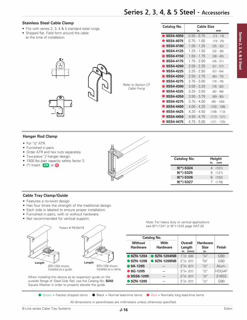
Series 2, 3, 4, &
5 Steel
Series 2, 3, 4, & 5 Steel - Accessories
J-16B-Line series Cable Tray Systems Eaton
All dimensions in parentheses are millimeters unless otherwise specified.
Catalog No. Cable Sizein. mm
9SS4-4050 0.50 - 0.75 (13 - 19)
9SS4-4075 0.75 - 1.00 (19 - 25)
9SS4-4100 1.00 - 1.25 (25 - 32)
9SS4-4125 1.25 - 1.50 (32 - 38)
9SS4-4150 1.50 - 1.75 (38 - 45)
9SS4-4175 1.75 - 2.00 (45 - 51)
9SS4-4200 2.00 - 2.25 (51 - 57)
9SS4-4225 2.25 - 2.50 (57 - 64)
9SS4-4250 2.50 - 2.75 (64 - 70)
9SS4-4275 2.75 - 3.00 (70 - 76)
9SS4-4300 3.00 - 3.25 (76 - 82)
9SS4-4325 3.25 - 3.50 (82 - 89)
9SS4-4350 3.50 - 3.75 (89 - 95)
9SS4-4375 3.75 - 4.00 (95 - 100)
9SS4-4400 4.00 - 4.25 (100 - 106)
9SS4-4425 4.25 - 4.50 (106 - 113)
9SS4-4450 4.50 - 4.75 (113 - 121)
9SS4-4475 4.75 - 5.00 (121 - 125)
Refer to Section CFCable Fixing
Green = Fastest shipped items Black = Normal lead-time items Red = Normally long lead-time items
Cable Tray Clamp/Guide• Features a no-twist design.• Has four times the strength of the traditional design.• Each side is labeled to ensure proper installation.• Furnished in pairs, with or without hardware.• Not recommended for vertical support.
Stainless Steel Cable Clamp• Fits with series 2, 3, 4 & 5 standard steel rungs.• Shipped flat. Field form around the cableat the time of installation.
Hanger Rod Clamp
• For 1/2" ATR.• Furnished in pairs.• Order ATR and hex nuts separately.• Two-piece "J"-hanger design.• 1500 lbs./pair capacity safety factor 3. • (*) Insert orZN G
Catalog No. Heightin. mm
9(*)-5324 4 (101)9(*)-5325 5 (127)9(*)-5326 6 (152)9(*)-5327 7 (178)
Note: For heavy duty or vertical applications see 9(*)-1241 or 9(*)-1242 page HAT-20
Catalog No.Without With Overall HardwareHardware Hardware Length Size Finish
in. (mm) in.
9ZN-1204 9ZN-1204NB 11/2 (38) 1/4" G909ZN-1208 9ZN-1208NB 21/4 (57) 3/8" G909A-1205 -- 21/4 (57) 1/2" Alum.9G-1205 -- 21/4 (57) 1/2" HDGAF9SS6-1205 -- 21/4 (57) 1/2" 316SS9ZN-1205 -- 21/4 (57) 1/2" G90
9ZN-1204 shown.Installed as a guide.
9ZN-1208 shown.Installed as a clamp.
Patent # RE35479
Length Length
When installing this device as an expansion guide on theoutside flange of Steel Side Rail, use the Catalog No. B202Square Washer in order to properly elevate the guide.
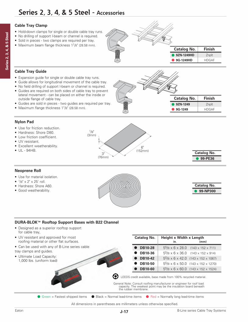
Series 2, 3, 4, & 5 Steel
All dimensions in parentheses are millimeters unless otherwise specified.
Series 2, 3, 4, & 5 Steel - Accessories
J-17 B-Line series Cable Tray SystemsEaton
1/8"(3mm)
3"(76mm)
6"(152mm)
Green = Fastest shipped items Black = Normal lead-time items Red = Normally long lead-time items
Cable Tray Clamp
• Hold-down clamps for single or double cable tray runs.• No drilling of support I-beam or channel is required.• Sold in pieces - two clamps are required per tray.• Maximum beam flange thickness 11/8" (28.58 mm).
Cable Tray Guide
• Expansion guide for single or double cable tray runs.• Guide allows for longitudinal movement of the cable tray.• No field drilling of support I-beam or channel is required.• Guides are required on both sides of cable tray to preventlateral movement - can be placed on either the inside oroutside flange of cable tray.
• Guides are sold in pieces - two guides are required per tray.• Maximum flange thickness 11/8" (28.58 mm).
Nylon Pad
• Use for friction reduction.• Hardness: Shore D80.• Low friction coefficient.• UV resistant.• Excellent weatherability.• UL - 94HB.
Neoprene Roll
• Use for material isolation.• 1/8" x 2" x 25' roll.• Hardness: Shore A60.• Good weatherability.
DURA-BLOK™ Rooftop Support Bases with B22 Channel• Designed as a superior rooftop supportfor cable tray,
• UV resistant and approved for mostroofing material or other flat surfaces.
• Can be used with any of B-Line series cable tray clamps and guides.• Ultimate Load Capacity:1,000 lbs. (uniform load)
Catalog No.
99-PE36
Catalog No.
99-NP300
Catalog No. Finish9ZN-1249HD Znplt
9G-1249HD HDGAF
Catalog No. Finish9ZN-1249 Znplt
9G-1249 HDGAF
Catalog No. Height x Width x Lengthin. (mm)
DB10-28 55/8 x 6 x 28.0 (143 x 152 x 711)
DB10-36 55/8 x 6 x 36.0 (143 x 152 x 914)
DB10-42 55/8 x 6 x 42.0 (143 x 152 x 1067)
DB10-50 55/8 x 6 x 50.0 (143 x 152 x 1270)
DB10-60 55/8 x 6 x 60.0 (143 x 152 x 1524)
LEEDS credit available, base made from 100% recycled material.
General Note: Consult roofing manufacturer or engineer for roof loadcapacity. The weakest point may be the insulation board beneaththe rubber membrane.
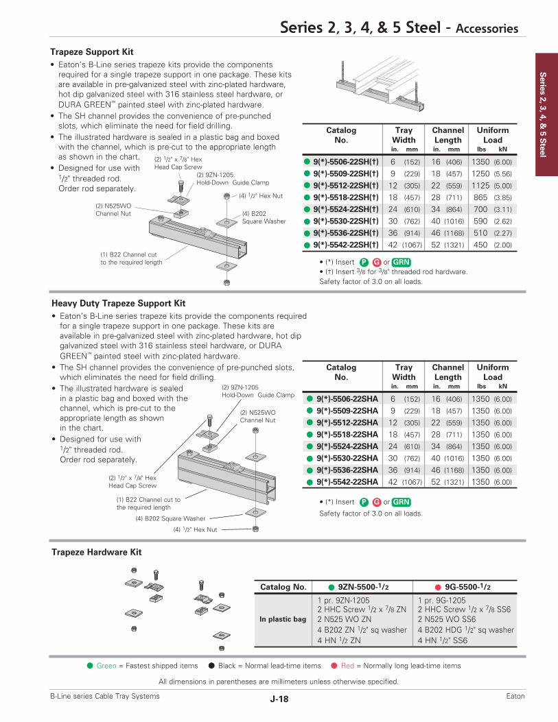
• (*) Insert or• (†) Insert 3/8 for 3/8" threaded rod hardware.Safety factor of 3.0 on all loads.
Series 2, 3, 4, &
5 Steel
Series 2, 3, 4, & 5 Steel - Accessories
J-18B-Line series Cable Tray Systems Eaton
All dimensions in parentheses are millimeters unless otherwise specified.
• (*) Insert or
Safety factor of 3.0 on all loads.
Catalog Tray Channel UniformNo. Width Length Load
in. mm in. mm lbs kN
9(*)-5506-22SH(†) 6 (152) 16 (406) 1350 (6.00)
9(*)-5509-22SH(†) 9 (229) 18 (457) 1250 (5.56)
9(*)-5512-22SH(†) 12 (305) 22 (559) 1125 (5.00)
9(*)-5518-22SH(†) 18 (457) 28 (711) 865 (3.85)
9(*)-5524-22SH(†) 24 (610) 34 (864) 700 (3.11)
9(*)-5530-22SH(†) 30 (762) 40 (1016) 590 (2.62)
9(*)-5536-22SH(†) 36 (914) 46 (1168) 510 (2.27)
9(*)-5542-22SH(†) 42 (1067) 52 (1321) 450 (2.00)(1) B22 Channel cutto the required length
(2) 9ZN-1205Hold-Down Guide Clamp
(4) B202Square Washer
(2) N525WOChannel Nut
(2) 1/2" x 7/8" HexHead Cap Screw
(4) 1/2" Hex Nut
Catalog No. 9ZN-5500-1/2 9G-5500-1/2
1 pr. 9ZN-1205 1 pr. 9G-12052 HHC Screw 1/2 x 7/8 ZN 2 HHC Screw 1/2 x 7/8 SS62 N525 WO ZN 2 N525 WO SS64 B202 ZN 1/2" sq washer 4 B202 HDG 1/2" sq washer4 HN 1/2 ZN 4 HN 1/2" SS6
In plastic bag
Green = Fastest shipped items Black = Normal lead-time items Red = Normally long lead-time items
Catalog Tray Channel UniformNo. Width Length Load
in. mm in. mm lbs kN
9(*)-5506-22SHA 6 (152) 16 (406) 1350 (6.00)
9(*)-5509-22SHA 9 (229) 18 (457) 1350 (6.00)
9(*)-5512-22SHA 12 (305) 22 (559) 1350 (6.00)
9(*)-5518-22SHA 18 (457) 28 (711) 1350 (6.00)
9(*)-5524-22SHA 24 (610) 34 (864) 1350 (6.00)
9(*)-5530-22SHA 30 (762) 40 (1016) 1350 (6.00)
9(*)-5536-22SHA 36 (914) 46 (1168) 1350 (6.00)
9(*)-5542-22SHA 42 (1067) 52 (1321) 1350 (6.00)
Trapeze Hardware Kit
Heavy Duty Trapeze Support Kit• Eaton’s B-Line series trapeze kits provide the components required for a single trapeze support in one package. These kits areavailable in pre-galvanized steel with zinc-plated hardware, hot dip galvanized steel with 316 stainless steel hardware, or DURAGREEN™ painted steel with zinc-plated hardware.
• The SH channel provides the convenience of pre-punched slots,which eliminates the need for field drilling.
• The illustrated hardware is sealed in a plastic bag and boxed with thechannel, which is pre-cut to the appropriate length as shownin the chart.
• Designed for use with1/2" threaded rod. Order rod separately.
Trapeze Support Kit• Eaton’s B-Line series trapeze kits provide the componentsrequired for a single trapeze support in one package. These kits are available in pre-galvanized steel with zinc-plated hardware,hot dip galvanized steel with 316 stainless steel hardware, or DURA GREEN™ painted steel with zinc-plated hardware.
• The SH channel provides the convenience of pre-punchedslots, which eliminate the need for field drilling.
• The illustrated hardware is sealed in a plastic bag and boxedwith the channel, which is pre-cut to the appropriate lengthas shown in the chart.
• Designed for use with1/2" threaded rod. Order rod separately.
(2) 9ZN-1205Hold-Down Guide Clamp
(4) 1/2" Hex Nut
(2) 1/2" x 7/8" HexHead Cap Screw
(1) B22 Channel cut tothe required length
(4) B202 Square Washer
(2) N525WOChannel Nut
GRNGP
GRNGP

Series 2, 3, 4, & 5 Steel
All dimensions in parentheses are millimeters unless otherwise specified.
Series 2, 3, 4, & 5 Steel - Accessories
J-19 B-Line series Cable Tray SystemsEaton
Catalog Tray ChannelNo. Width Length
in. (mm) in. (mm)
9ZN-5212 6", 9", 12" (152, 228, 305) 18" (457)9ZN-5224 18", 24" (457, 609) 30" (762)
Catalog No. Uniform Load Tray Width 'A'lbs kN in. mm in. mm
B494-30 924 (4.11) 24 (610) 30 (762)
B494-36 864 (3.84) 30 (762) 36 (914)
B494-42 580 (2.58) 36 (914) 42 (1067)
B494-48 500 (2.22) 42 (1067) 48 (1219)
(1) 9/16" Inside diameter steeltubing welded to strut
Catalog No. Uniform Load Tray Width 'A'lbs kN in. mm in. mm
B494-12 1580 (7.02) 6 & 9 (152 & 229) 12 (305)
B494-18 1000 (4.45) 12 (305) 18 (457)
B494-24 996 (4.43) 18 (457) 24 (610)
A
A
Green = Fastest shipped items Black = Normal lead-time items Red = Normally long lead-time items
Center Hung Tray Support
• Center Hung Cable Tray Support allowscable to be laid-in from both sides.
• Eliminates costly cable pulling and fieldcutting of cable tray supports. Labor costs are dramatically reduced.
• Required hardware and threaded rodmaterial for trapeze assemblies arereduced by up to 50%.
• Designed for use with 1/2" threaded rod. (Order rod separately)
• Use with all aluminum and steel cable trays through 24" width.
• Load capacity is 700 lbs. (311kN) per support.Safety factor of 3.0.Eccentric loading is not to exceed a60% vs. 40% load differential.
• The maximum recommended unsupportedspan length is 144"/12 ft. (3.66 m).
• Hardware shown is furnished.• Finish available: Zinc Plated
Center Hung Support Hardware Kit
Bracket
• (*) Insert available finish:or
• Safety Load Factor 2.5
Bracket• (*) Insert available finish:
or• Safety Load Factor 2.5
Cantilever Bracket• (*) Insert available finish:
or• Safety Load Factor 2.5
ZN GRN HDG
Catalog No. 9ZN-5200
1 pr. 9ZN-12052 HHC Screw 1/2 x 7/8 ZN2 N525 WO ZN1 B202 ZN 1/2" sq washer4 HN 1/2 ZN
In plastic bag
(2) 9ZN-1205Hold-DownGuide Clamp
(2) 1/2" Hex Nut (2) 1/2" x 7/8" HexHead Cap Screw
(1) B22 Channel cut tothe required length
(1) B202 Square Washer
(2) N525WOChannel Nut
Catalog No. Uniform Load Tray Width 'A'lbs kN in. mm in. mm
B409-12 960 (4.27) 6 & 9 (152 & 229) 12 (305)
B409-18 640 (2.84) 12 (305) 18 (457)
B409-24 480 (2.13) 18 (457) 24 (610)
AZN GRN HDG
ZN GRN HDG
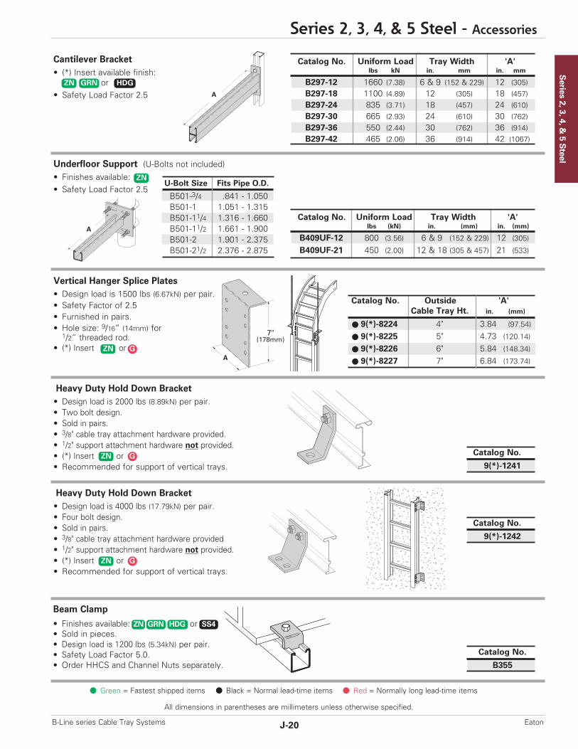
Series 2, 3, 4, &
5 Steel
Series 2, 3, 4, & 5 Steel - Accessories
J-20B-Line series Cable Tray Systems Eaton
All dimensions in parentheses are millimeters unless otherwise specified.
A
A
7"(178mm)
A
Catalog No. Outside 'A'Cable Tray Ht. in. (mm)
9(*)-8224 4" 3.84 (97.54)
9(*)-8225 5" 4.73 (120.14)
9(*)-8226 6" 5.84 (148.34)
9(*)-8227 7" 6.84 (173.74)
U-Bolt Size Fits Pipe O.D.
B501-3/4 .841 - 1.050B501-1 1.051 - 1.315B501-11/4 1.316 - 1.660B501-11/2 1.661 - 1.900B501-2 1.901 - 2.375B501-21/2 2.376 - 2.875
Green = Fastest shipped items Black = Normal lead-time items Red = Normally long lead-time items
Heavy Duty Hold Down Bracket• Design load is 2000 lbs (8.89kN) per pair.• Two bolt design.• Sold in pairs.• 3/8" cable tray attachment hardware provided.• 1/2" support attachment hardware not provided.• (*) Insert or• Recommended for support of vertical trays.
Cantilever Bracket• (*) Insert available finish:
or• Safety Load Factor 2.5
Catalog No. Uniform Load Tray Width 'A'lbs kN in. mm in. mm
B297-12 1660 (7.38) 6 & 9 (152 & 229) 12 (305)B297-18 1100 (4.89) 12 (305) 18 (457)B297-24 835 (3.71) 18 (457) 24 (610)B297-30 665 (2.93) 24 (610) 30 (762)B297-36 550 (2.44) 30 (762) 36 (914)B297-42 465 (2.06) 36 (914) 42 (1067)
ZN GRN HDG
Underfloor Support (U-Bolts not included)• Finishes available: • Safety Load Factor 2.5
Catalog No. Uniform Load Tray Width 'A'lbs (kN) in. (mm) in. (mm)
B409UF-12 800 (3.56) 6 & 9 (152 & 229) 12 (305)
B409UF-21 450 (2.00) 12 & 18 (305 & 457) 21 (533)
ZN
Vertical Hanger Splice Plates• Design load is 1500 lbs (6.67kN) per pair.• Safety Factor of 2.5• Furnished in pairs.• Hole size: 9/16” (14mm) for
1/2” threaded rod.• (*) Insert or
ZN Catalog No.
9(*)-1241
Heavy Duty Hold Down Bracket• Design load is 4000 lbs (17.79kN) per pair.• Four bolt design.• Sold in pairs.• 3/8" cable tray attachment hardware provided• 1/2" support attachment hardware not provided.• (*) Insert or• Recommended for support of vertical trays.
ZN
Catalog No.
9(*)-1242
Beam Clamp
• Finishes available: or• Sold in pieces.• Design load is 1200 lbs (5.34kN) per pair.• Safety Load Factor 5.0.• Order HHCS and Channel Nuts separately.
ZN GRN HDG SS4
Catalog No.
B355
ZN G
G
G
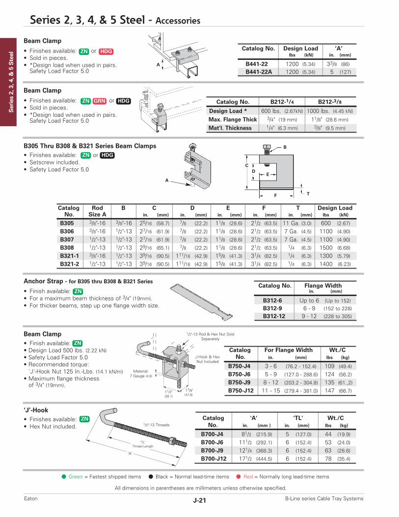
Series 2, 3, 4, & 5 Steel
All dimensions in parentheses are millimeters unless otherwise specified.
Series 2, 3, 4, & 5 Steel - Accessories
J-21 B-Line series Cable Tray SystemsEaton
Catalog No. Flange Widthin. (mm)
B312-6 Up to 6 (Up to 152)B312-9 6 - 9 (152 to 228)B312-12 9 - 12 (228 to 305)
Catalog 'A' 'TL' Wt./CNo. in. (mm ) in. (mm) lbs (kg)
B700-J4 81/2 (215.9) 5 (127.0) 44 (19.9)
B700-J6 111/2 (292.1) 6 (152.4) 53 (24.0)
B700-J9 121/4 (368.3) 6 (152.4) 63 (28.6)
B700-J12 171/2 (444.5) 6 (152.4) 78 (35.4)
Catalog Rod B C D E F T Design LoadNo. Size A in. (mm) in. (mm) in. (mm) in. (mm) in. (mm) lbs (kN)
B305 3/8"-16 3/8"-16 25/16 (58.7) 7/8 (22.2) 11/8 (28.6) 21/2 (63.5) 11 Ga. (3.0) 600 (2.67)
B306 3/8"-16 1/2"-13 27/16 (61.9) 7/8 (22.2) 11/8 (28.6) 21/2 (63.5) 7 Ga. (4.5) 1100 (4.90)
B307 1/2"-13 1/2"-13 27/16 (61.9) 7/8 (22.2) 11/8 (28.6) 21/2 (63.5) 7 Ga. (4.5) 1100 (4.90)
B308 1/2"-13 1/2"-13 29/16 (65.1) 7/8 (22.2) 11/8 (28.6) 21/2 (63.5) 1/4 (6.3) 1500 (6.68)
B321-1 3/8"-16 1/2"-13 39/16 (90.5) 111/16 (42.9) 15/8 (41.3) 31/4 (82.5) 1/4 (6.3) 1300 (5.79)
B321-2 1/2"-13 1/2"-13 39/16 (90.5) 111/16 (42.9) 15/8 (41.3) 31/4 (82.5) 1/4 (6.3) 1400 (6.23)
Catalog No. B212-1/4 B212-3/8
Design Load * 600 lbs. (2.67kN) 1000 lbs. (4.45 kN)Max. Flange Thick 3/4" (19 mm) 11/8" (28.6 mm)Mat'l. Thickness 1/4" (6.3 mm) 3/8" (9.5 mm)
B
ED
C
F T
A
A
Material: 7 Gauge (4.6)
1/2"-13 Rod & Hex Nut SoldSeparately
1/2"-13 Threads
11/2"(38.1)
‘A’
‘TL’Thread Length
17/8"(47.6)
J-Hook & Hex Nut Included
Catalog For Flange Width Wt./CNo. in. (mm) lbs (kg)
B750-J4 3 - 6 (76.2 - 152.4) 109 (49.4)
B750-J6 5 - 9 (127.0 - 288.6) 124 (56.2)
B750-J9 8 - 12 (203.2 - 304.8) 135 (61.,2)
B750-J12 11 - 15 (279.4 - 381.0) 147 (66.7)
ZN HDG
ZN GRN HDG
ZN
ZN HDG
ZN
ZN
Catalog No. Design Load ‘A’lbs (kN) in. (mm)
B441-22 1200 (5.34) 33/8 (86)B441-22A 1200 (5.34) 5 (127)
Green = Fastest shipped items Black = Normal lead-time items Red = Normally long lead-time items
Beam Clamp
• Finishes available: or• Sold in pieces.• *Design load when used in pairs.Safety Load Factor 5.0
Anchor Strap - for B305 thru B308 & B321 Series
• Finish available:• For a maximum beam thickness of 3/4" (19mm).• For thicker beams, step up one flange width size.
Beam Clamp• Finish available: • Design Load 500 lbs. (2.22 kN)• Safety Load Factor 5.0• Recommended torque: 'J'-Hook Nut 125 In.-Lbs. (14.1 kN/m)
• Maximum flange thicknessof 3/4" (19mm).
B305 Thru B308 & B321 Series Beam Clamps• Finishes available: or• Setscrew included.• Safety Load Factor 5.0
Beam Clamp
• Finishes available: or• Sold in pieces.• *Design load when used in pairs.Safety Load Factor 5.0
‘J’-Hook• Finishes available: • Hex Nut included.

Series 2, 3, 4, &
5 Steel
J-22B-Line series Cable Tray Systems Eaton
All dimensions in parentheses are millimeters unless otherwise specified.
Steel Cover Part NumberingPrefix
Example: 80 2 P - 24 - 144
Cover Type Detail Material Tray Width Item Description80 = Solid 2 = Flanged Steel (248,258, 268 P = Pre-Galvanized 06 = 6" For Straight Section Cover:81 = Ventilated straight sections and all fittings) (Not available in 09 = 9" Pre-Galvanized Only82 = Peaked 3 = Flanged Steel (all straight Type 83) 12 = 12" 144 = 12 ft. (3.66 m)
sections except 248, 258, 268) G = HDGAF 18 = 18" 120 = 10 ft. (3.05 m)4 = Non-Flanged Steel (80 & 81 24 = 24" Pre-Galvanized & HDGAFtype only) 30 = 30" 72 = 6 ft. (1.83 m)
36 = 36" 60 = 5 ft. (1.52 m)For fitting covers: Insert suffix
of fitting to be covered.See example below.
Examples of Catalog Numbers for Fitting Covers:
A full range of covers is available for straight sections and fittings.
Solid covers should be used when maximum enclosure of the cable is desired and no accumulation of heat is expected. Ventilated covers provide an overhead cable shield, yet allow heat to escape.We recommend that covers be placed on vertical cable tray runs to a height of 6 ft. (1.83 m) to 8 ft. (2.44 m) above the floor toisolate both cables and personnel. Flanged covers have a 1/2 in. (13 mm) flange. Cover clamps are not included with the cover and mustbe ordered separately. All peaked covers are flanged. Standard peaked covers have 1/2" peak. Special purpose peaked covers, having a2 to 3 pitch, provide additional slope and material thickness. The 2 to 3 pitch fitting covers are of multiple piece, welded construction.
Solid Flanged Ventilated Flanged Peaked Flanged 2 to 3 PitchPeaked Flanged(See page APP-4)
Vertical Bend CoverPrefix Suffix
80 2 G - 24 - 90 VO 24 - 4*Side Rail*Height RadiusFittingAngleWidthMaterialDetailCover Type
Solid Non-Flanged
Covers
Horizontal Bend CoverPrefix Suffix
80 2 P - 18 - 90 HB 24
RadiusFittingAngleWidthMaterialDetailCover Type
* Required for VO fittings only
Green = Fastest shipped items Black = Normal lead-time items Red = Normally long lead-time items
Series 2, 3, 4, & 5 Steel - Accessories

Series 2, 3, 4, & 5 Steel
All dimensions in parentheses are millimeters unless otherwise specified.
Series 2, 3, 4, & 5 Steel - Accessories
J-23 B-Line series Cable Tray SystemsEaton
Straight Section 60" or 72" ....................................... 4 pcs.Straight Section 120" or 144" ................................. 6 pcs.Horizontal/Vertical Bends .......................................... 4 pcs.Tees ........................................................................................... 6 pcs.Crosses ................................................................................... 8 pcs.
Peaked Cover Clamp
TrefoilCableCleats
SingleCableCleats
Green = Fastest shipped items Black = Normal lead-time items Red = Normally long lead-time items
Standard Cover Clamp
• For indoor service only.• Screw included.• Sold per piece.• (*) Insert or
Combination Cover and Hold Down Clamp
• Sold per piece.• For indoor service only.• (*) Insert or
Raised Cover Clamp
• For indoor service only.• For use with flanged covers only.† Specify gap of 1", 2", 3" or 4".
Quantity of Standard Cover Clamps Required
Notes: When using the Heavy Duty Cover Clamp, only on-halfthe number of clamps stated above is required.Additional clamps may be necessary in extreme wind applications.
Cable Cleats(see pages O-1 thru O-5) Standard
Heavy Duty Cover Clamp
• Recommended for outdoor service.• (‡) Insert tray width† Add P to Catalog No.for peaked cover clamp.
• (*) Insert or
Conduit to Cable Tray Adaptor
• Used to join covers• Plastic• (‡) Insert tray width
Tray Type Catalog No. Tray Type
9ZN-9114-† Series 2 Steel Straight Section9ZN-9115-† Series 3 & 4 Steel Straight Section9ZN-910† All Steel Fittings (Also Series 1
Steel Straight Sections)
Tray Type Catalog No. Side Rail Heightin. (mm)
9(*)-9043 4 (101)
Steel 9(*)-9053 5 (127)
9(*)-9063 6 (152)
9(*)-9073 7 (78)
Tray Type Catalog No. Side Rail Heightin. (mm)
9(*)-9014 4 (101)
Steel 9(*)-9015 5 (127)
9(*)-9016 6 (152)
9(*)-9017 7 (78)
Catalog No.
99-9980-(‡)
Catalog No. Side Rail Heightin. mm
9(*)-(‡)-9044† 4 (101)9(*)-(‡)-9054† 5 (127)9(*)-(‡)-9064† 6 (152)9(*)-(‡)-9074† 7 (178)
GP
GP
ZN G

Section 1- Acceptable Manufacturers1.01 Manufacturer: Subject to compliance with these specifications, Eaton’s B-Line series cable tray systems shall be as
manufactured by Eaton.
Section 2- Cable Tray Sections and Components2.01 General: Except as otherwise indicated, provide metal cable trays, of types, classes and sizes indicated;
with splice plates, bolts, nuts and washers for connecting units. Construct units with rounded edgesand smooth surfaces; in compliance with applicable standards; and with the following additional construction features. Cable tray shall be installed according to the latest revision of NEMA VE 2.
2.02 Pre-Galvanized Steel: Straight sections, fitting side rails, rungs, and covers shall be made fromstructural quality steel meeting the minimum mechanical properties and mill galvanized in accordancewith ASTM A653 SS, Grade 33, coating designation G90. Hardware finish shall be electrogalvanizedzinc per ASTM B633.
2.03 Hot Dip Galvanized Steel: All side rails, covers, splice plates, and rungs shall be made from structuralquality steel meeting the minimum mechanical properties of ASTM A1011 SS, Grade 33 for 14 gaugeand heavier, ASTM A1008, Grade 33 Type 2 for 16 gauge and lighter, and shall be hot dip galvanizedafter fabrication in accordance with ASTM A123. Mill galvanized covers are not acceptable for hot dipgalvanized cable tray. Hardware finish shall be chromium zinc per ASTM F-1136-88.
2.04 Ladder Cable Trays shall consist of two longitudinal members (side rails) with transverse members(rungs) welded to the side rails. Rungs shall be spaced [6] [9] [12] inches on center. Rung spacing inradiused fittings shall be industry standard 9" and measured at the center of the tray’s width. No portion of the rungs shall protrude below the bottom plane of the side rails. Each rung must be capable of supporting a 200 lb. concentrated load at the center of the cable tray over and above thecable load with a safety factor of 1.5.
2.05 Ventilated Trough Cable Trays shall consist of two longitudinal members (side rails) with a corrugatedbottom welded to the side rails or rungs spaced 4" on center. The peaks of the corrugated bottomshall have a minimum flat cable bearing surface of 23/4" and shall be spaced on 6" centers. Toprovide ventilation in the tray, the valleys of the corrugated bottom shall have 21/4" x 4" rectangularholes punched along the width of the bottom.
2.06 Non-Ventilated Bottom Trough Cable Trays shall consist of two longitudinal members (side rails) with acorrugated bottom welded to the side rails or a solid sheet over rungs. The peaks of the corrugatedbottom shall have a minimum flat cable bearing surface of 23/4" and shall be spaced on 6" centers.
2.07 Cable tray loading depth shall be [3] [4] [5] [6] inches per NEMA VE 1.
2.08 Straight sections shall have side rails fabricated as I-beams. Straight sections shall be supplied instandard [12 foot] [24 foot] [10 foot (3 m)] [20 foot (6 m)] lengths.
2.09 Cable tray widths shall be [6] [9] [12] [18] [24] [30] [36] inches or as shown on drawings.
2.10 Splice plates shall be manufactured of high strength steel, meeting the minimum mechanical propertiesof ASTM A1011 HSLAS, Grade 50, Class 1 and be secured with 8 nuts and bolts per plate. Theresistance of fixed splice connections between an adjacent section of tray shall not exceed 0.00033 ohm.
2.11 All fittings must have a minimum radius of [12] [24] [36] [48] inches.
Section 3- Loading Capacities and Testing
3.01 Cable tray shall be capable of carrying a uniformly distributed load of ______ lbs./ft. on a _______ ft.support span with a safety factor of 1.5 when supported as a simple span and tested per NEMAVE 1 5.2. In addition to the uniformly distributed load the cable tray shall support 200 lbs. concentratedload at mid-point of span. Load and safety factors specified are applicable to both the side rails andrung capacities. Cable tray shall be made to manufacturing tolerances as specified by NEMA.
3.02 Upon request, manufacturer shall provide test reports in accordance with the latest revision ofNEMA VE 1 or CSA C22.2 No. 126.
Series 2, 3, 4, &
5 Steel
Series 2, 3, 4, & 5 Steel - Specifications
J-24B-Line series Cable Tray Systems Eaton