series 1640/1650 printers and terminals … · printers and terminals product description 90412-01...
TRANSCRIPT

SERIES 1640/1650
PRINTERS and TERMINALS
PRODUCT DESCRIPTION
90412-01 Rev B Apr., 1980
DIABLO SYSTEMS, Inc. A XEROX Company

WARRANTY
Diablo Series 1640/1650 Printers and Terminals are warranted against defects in materials and workmanship for 90 days from the date of shipment. Any questions regarding the warranty should be directed to your Diablo Sales Representative.
All requests for repairs should be directed to the Diablo Service Center in your area. This will assure you the fastest possible service.
UL recognized and listed under File No. E5l242 CSA certified as a component under File No. LR2l96
PREFACE
Diablo Systems, Incorporated, reserves the right to make changes and/ or improvements to its products without incurring any obligation to incorporate such changes or improvements in units previously sold or shipped.
Diablo publishes descriptive Brochures and Data Sheets, a Product Description Manual, a Maintenance Manual, a Parts Catalog, and a Parts Price List for each product line. In addition~ important changes to a product are conveyed to the field in the form of Field Service Aids sent to all product customers of record.
Those changes which alter manual content are covered by publishing an Addenda to the affected manual.
Diablo publications may be requested from your Diablo Sales Representative, or may be ordered from Diablo in the same manner as spare parts.
Comments on all Diablo publications or their use are invited. Please use the Comment Form at the back of this manual, or address your comments to:
Manager, Customer Service Publications Diablo Systems, Incorporated
3190 Corporate Place Hayward, California, U. S. A. 94545
Diablo@, HyType®, and XEROX® are trademarks of Xerox Corporation HyTerrn and HyFeed are trademarks of Diablo Systems, Inc.
©Copyright 1979 by Diablo Systems, Inc., Hayward, Ca., USA
Publication No. 90412-01 Second Edition, Series 1640/1650
Previous Editions: First - 90402-00 - March 1979 (preliminary) Series 1650 First - 90412-00 - March 1979 (preliminary) Series 1640
Printed in u. S. A.

REVISION CONTROL RECORD 1640/1650 SERIES PRODUCT DESCRIPTION - PUBLICATION NO. - - - -
NOTE:
- - - -PAGE/REV Cover B i B ii A iii A iv A v A vi A
1-1 A 1-2 A 1-3 B 1-4 B 1-5 A 1-6 A 1-7 A 1-8 A 1-9 A
1-10 A 1-11 A
2-1 A 2-2 A 2-3 A 2-4 A 2-5 B 2-6 B 2-7 A 2-8 A 2-9 A
2-10 A 2-11 A 2-12 A 2-13 A 2-14 A 2-15 A 2-16 A 2-17 A 2-18 A 2-19 A 2-20 A 2-21 A 2-22 B 2-23 B 2-24 A 2-25 A 2-26 A
- - - - - - - - - - - - - - - - - - - - - -On revised pages of text, a heavy vertical margin indicates each area of new revision. - - - - - - - - - - - - - - - - - - - -
PAGE/REV PAGE/REV 2-27 A A-I 2-28 A A-2 2-29 B A-3 2-30 A A-4 2-31 A A-5 2-32 A A-6 2-33 A
B-1 3-1 B B-2 3-2 A B-3 3-3 B B-4 3-4 A B-5 3-5 A B-6 3-6 A B-7 3-7 A B-8 3-8 A B-9 3-9 A B-I0
B-ll 4-1 A B-12 4-2 A B-13 4-3 A
C-l 5-1 A C-2
C-3 6-1 B C-4 6-2 B C-5 6-3 A 6-4 B D-l 6-5 B D-2 6-6 A D-3 6-7 B D-4 6-8 A 6-9 A E-l
6-10 A E-2 6-11 B E-3 6-12 A 6-13 A 6-14 A 6-15 A 6-16 A 6-17 A 6-18 A 6-19 A 6-20 A 6-21 A
90412-01 REV B (4/80) i
A A A A A A
B A B A A A A A A A A A A
A A A A A
A A A A
A A A
- -
-bar
-
90412-01 - - - - - -
in the
- -


TABLE OF CONTENTS
SECTION 1 - GENERAL DESCRIPTION AND SPECIFICATIONS 1.1 Introduction. • • . •• . • . • • . • • • • • . 1-1
1.1.1 Description.. . . . 1-1 1.1.2 Features • • • •.. • • • • . • 1-2
1.1.2.1 Serial Interface. •••. .••. 1-2 1.1.2.2 Parallel Interface.. .• • . • . 1-2 1.1.2.3 Current Loop Interface. . . . . . . . . . 1-2 1.1.2.4 Keyboard Input. . . . • . • . • • . • • . 1-2
1.2 General Specifications. • . . . . . • . • . • • . . • . 1-3 1.2.1 The Print Mechanism (OEM Version) . •• ••. 1-3 1.2.2 The RO Printer . • • . • •. •. • • • . 1-3 1.2.3 The KSR Terminal • . • . . . • . . . • • • • 1-5 1.2.4 Programmable Functions (ESC sequences) ••• 1-5 1.2.5 Accessor ies and Options • . . • • . • • . 1-6 1.2.6 Performance Specifications . • • •..• • . 1-7
1.3 Print Speed Measurements • . . . • . • •. . 1-10 1.3.1 Performance Criteria . • •. • •.•.. 1-10 1.3.2 Performance Tests. . . • . • • . • . • • . . 1-10 1.3.3 Print Speeds . . . . . •.. 1-10
SECTION 2 - INSTALLATION AND OPERATION 2.1 Installation •. --.-. • . . . . . . . • . . • . . 2-1
2.1.1 Space Requirements ... • . . • . . 2-1 2.1.2 Mounting ••• . . . • . . • • . . . • . 2-8 2.1.3 External Power Supply Requirements • . . 2-8 2.1.4 Grounding Requirements . . • . . . • . . 2-9
2.2 Interconnecting Cables. • . • • . • 2-9 2.2.1 The Power Cable. . . • . . . • . . • . . 2-9 2.2.2 The Serial Interface Cable • •. • . . . 2-10 2.2.3 The Parallel Interface Cable .... 2-10 2.2.4 The Current Loop Interface Cable ..••.. 2-10
2.3 Ventilation • • . • . . . . . . • .. . 2-12 2.4 Operation • • . . • . . . . • •• . 2-12
2.4.1 General Procedures ... ..•.• . . . 2-12 2.4.1.1 Paper Loading .•.. 2-13 2.4.1.2 Paper Thickness Adjustment .•.. 2-13 2.4.1.3 Ribbon Cartridge Replacement. . •.• 2-13 2.4.1.4 Print Wheel Replacement • • . • •. . 2-15 2.4.1.5 Print Intensity Adjustment •.• . 2-15 2.4.1.6 Top Paper Out Switch. . .. . 2-15 2.4.1.7 End Of Ribbon Sensor. • • •. • •.• 2-16 2.4.1.8 Cover Open Switch • •• • 2-16 2.4.1.9 Internal Switches . • • • • • . •. • 2-16
2.4.2 The RO Printer .•..• .•• • • .. • 2-18 2.4.2.1 General Operating Procedures. • .• • 2-18 2.4.2.2 Operator Control Panel. • . • . . • • 2-18
2.4.3 The KSR Terminal • . • . . • . • • • . •• • 2-21 2.4.3.1 General Operating Procedures. . .. • 2-21 2.4.3.2 The Diablo Keyboard • .. • .• • 2-21
2.4.4 Printing Format. . . . • . • . • . •.• 2-24 2.4.4.1 Definition of Terms • .• . .. • 2-25 2.4.4.2 Standard Formats. • • • • . •.• 2-26 2.4.4.3 Optional Formats (Variable Indexing) • 2-28 2.4.4.4 Variable HMI . . • • • • •. • 2-28 2.4.4.5 Variable VMI . . . . • . • . . . .. . 2-28
Rev A (10/79) ii

2.4.4.6 Lines Per Page · · · · · . · · 2.4.4.7 Forward/Backward Printing 2.4.408 Print Suppression 2.4.4.9 Margin Control · · · · · · · · 2.4.4.10 Tabbing · · · 2.4.4.11 Line Feed · · · · · · · · · · 2.4.4.12 Form Feed · · · · · · · . · · 2.4.4.13 Graphics . · · · · · · 2.4.4.14 Two-Color Printing 2.4.4.15 Restore (Initialization) · · ·
SECTION 3 - INTERFACE 3.1 -General Information ••. 3.2 Remote ASCII (ANSI) Mode . • ••.••••• 3.3 Remote 2741 Mode (Option) •••
3.3.1 Control Codes ••.••••• 3.3.2 2741 Mode Interface Line Control .••.
3.3.2.1 Initialization •••••• 3.3.2.2 Transmit/Receive Interchange. 3.3.2.3 Interrupt .•••••••••
3.4 Input/Output Gates.. . ••
3.5 3.6 3.7 3.8
3.4.1 Input Gates • • • • • 3.4.2 Output Gates • •. • •• Data Transfer Timing • • • • Restore Timing • • • • • • • • • Dial Up • • • • • • • •• ••• I/O Signals - Parallel ASCII • • • . 3.8.1 -Character Strobe. • .• 3.8.2 -Char acter Ready . . • • . • 3.8.3 -Restore • •• . ••.• 3.8.4 -Clear .•.• • .. 3.8.5 -Data Bits 0-7 .•• 3.8.6 -Status Strobe •••••.• 3.8.7 -Status Bits 0-7 .•••••
3.9 I/O Signals - Serial RS-232-C ••• 3.9.1 EIA Interface Signals ••.• 3.9.2 Printer Ready Signal ••.•.••••.
SECTION 4 - PRINCIPLES OF OPERATION 4.1 -General Information .•.•.• 4.2 Universal Interface •••.•• 4.3 The Printer .....•.••.
SECTION 5 - MAINTENANCE 5.1 -General Information ••. 5.2 Preventive Maintenance 5.3 Maintenance Philosophy
5.3.1 Level One. 5.3.2 Level Two •••.• 5.3.3 Level Three
SECTION 6 - APPENDICES 6.1 -General Information •••.•••• 6 • 2 S u pp 1 i e s • • . • • •• •••••
iii
· · · · · · · · · · · · · · · · · · · · · · · · · ·
· · · · · · · · · ·
2-29 2-29 2 ..... 29 2-29 2-30 2-32 2-32 2-32 2-32 2-32
3-1 3-1 3-3 3-4 3-4 3-4 3-4 3-6 3-6 3-6 3-6 3-6 3-6 3-8 3-8 3-8 3-8 3-8 3-8 3-8 3-8 3-9 3-9 3-9 3-9
4-1 4-1 4-3
5-1 5-1 5-1 5-1 5-1 5-1
6-1 6 ..... 1
Rev A (10/79)

6.3 Accessories • • • . • • • • • • • . • • • • 6-1 6.3.1 Paper Handling Accessories • • • 6-1
6.3.1.1 Platens . • • . •• •.•.•• • 6-1 6.3.1.2 Forms Tractors. • • • • . • • . • • • 6-1 6.3.1.3 Bottom Feed • • • • • • • 6-2 6.3.1.4 Sheet Feeders • • • • • • • . . • • • 6-2
6.3.2 Cover Sets • • • • .• • 6-4 6.4 Options • • • • • • • • • • • • • • 6-4
6.4.1 Diablo Keyboard. •• • 'e. • • • • 6-5 6.4.2 H4CPN Operator Control Panel • • • . 6-5 6.4.3 XMEM2 Expanded Memory PCB Assembly • . • 6-5 6.4.4 Internal Power Supply. • • . • • . • • • • . 6-5 6.4.5 Current Loop Interface • • . • . • . . • • . 6-5 6.4.6 Word Processing Enhancements • • • • 6-6
6.4.6.1 Proportional Space Printing . • • 6-6 6.4.6.2 Offset Selection (Auto Prop. Spacing) 6-7 6.4.6.3 Auto Underscore •••• • • • . • • • 6-8 6.4.6.4 Bold Overprint. • • . • • • • . • • . 6-8 6.4.6.5 Shadow Print. • • • • • • • . • • • • 6-8 6.4.6.6 Carriage Settling Time. • • • 6-8 6.4.6.7 Half-Unit Backspace . • • • • 6-8 6.4.6.8 Program Mode. • • • • . • • • •. 6-9 6.4.6.9 Cancel Word Processing Options .••••. 6-10 6.4.6.10 Auto Center. • • • . •• •••. 6-10 6.4.6.11 Auto Justify • • • ••. • • 6-10 6.4.6.12 Line Edit.. • ••••••••.•. 6-11 6.4.6.13 Margin Control • • • • • • • 6-11
6.4.7 2741 Option Mode/Enhancements. . • • • • 6-11 6.4.8 HyPlot, Feeder, Diagnostics. • • • • • • 6-13
6.4.8.1 HyPlot Vector Plotting •.•••••.•• 6-13 6.4.8.2 Paper Feeder Options ••••••••••• 6-16 6.4.8.3 External (Remote) Diagnostics ••• . 6-16
6.4.9 Expanded Buffer •••••••••• • • 6-20 6.4.10 Keyboard Programmable "Here Is" . • •. 6-20 6.4.11 Baud Rate Option Mode • • • • • • • 6-21
APPENDIX A ASCII Code Chart • • • • • • • • • • • 2741 Codes • • • • • • • • • • IBM Correspondence Code • ••• IBM PTTC/EBCD Code • • • • • • IBM Correspondence Code (APL) IBM PTTC/EBCD Code (APL) •••
APPENDIX B Keyboards • • • • • • • • • • • • • • • • • • 47-Key Typewriter Paired ASCII Keyboard ••••• ASCII/APL Chart • • • • • • • • • • • • • • • • • • • • . 47-Key Typewriter Paired 2741 Correspondence Keyboard ••••
A-I A-2 A-3 A-4 A-5 A-6
B-1 B-2 B-3 B-4 B-5 2741 Correspondence Chart • • • • • • • • • • . •
47-Key Typewriter Paired 2741 PTTC/EBCD Keyboard • • • • B-6 2741 PTTC/EBCD Chart • • • • • • 47-Key Logical Bit Paired Keyboard • • • • • • . 47-Key APL Keyboard • • • • • • ••••• • . 47-Key French AZERTY Keyboard • • • • • •
Rev A (10/79) iv
B-7 B-8 B-9
• • B-lO

47-Key Scandinavian Keyboard • • • 47-Key German Keyboard • • • • 47-Key NORSK Keyboard • •
• B-ll • B-12 • B-13
APPENDIX C 96 Character Print Wheel - Plastic . . . · · · · · · · · 88 Character Print Wheel - Metal . . . . · · · · · · · · . ·
C-l C-2 C-3 C-4 C-5
92 Character Print Wheel - Metal (Rank Xerox) · · · · · · 96 Character Print Wheel - Metal (Diablo) · · · · · · . · 96 Character Print Wheel - Metal (Rank Xerox) · · · · APPENDIX D
Decimal Value Tables • • • • • • • • • • • • • • • • • • D-l ASCII Values for ESC Sequences (Set HMI, Set VMI) • • • • D-2 ASCII Values for ESC Sequences (Set Lines/page, Absolute
Horizontal Tab and Absolute Vertical Tab) ••••• D-3 Decimal Values for 2741 Characters • • • • • • • • • • • D-4
APPENDIX E. Character PS units - Metal Print Wheels • Character PS units - Plastic Print Wheel Print Wheel Program Mode - Characters for Hanuner Energy
E-l E-2
Figure 1-1 2-lA 2-lB 2-2 2-3 2-4 2-5 2-6 2-7 2-8 2-9
2-10 2-11 2-12 2-13 2-14 2-15 2-16 2-17 3-1 3-2 3-3 3-4 3-5 4-1 4-2 4-3 6-1
and Ribbon Advance • • • • • • • • • E-3
LIST OF ILLUSTRATIONS
Series 1640/1650 Printers and Terminals • • • • • • 1-1 Series 1640/1650 External Dimensions •••• 2-1 Ser les 1640/1650 External Dimensions . • • • • • . • • . 2-2 Diablo Unidirectional Forms Tractor • • • • •. 2-3 Diablo Bidirectional Forms Tractor • • • • • • • . • 2-4 Auto Front Feed and Bidirectional Forms Tractor •••• 2-5 Mechanical Front Feed • • • • • • • • • 2-6 HyFeed Sheet Feeder ••• . • • • • • • • •• ••• 2-7 Serial I/O Cable Connector Pin Assignment •••.••• 2-11 Parallel I/O Cable Connector Pin Assignment . • • • • • 2-11 Current Loop I/O Cable Connector Pin Assignment . • . • 2-12 Series 1640/1650 Controls and Connectors ••.••• 2-14 HPR04 Control Swi tch Module A25 ••.••••..•.. 2-16 Operator Control Panel • • • • • • • • . • • • • • • . . 2-18 Diablo Keyboard Sections • . . • . • • • . • . • 2-24 Standard Keyboard Assignments - KSR Models • • •• . 2-24 ESC Mode Key Assignments • • •• •• • • • • . . 2-25 CTRL Mode Key Assignments ••• •• • . ••.• 2-25 Page Layout and Printing Format . • •• • •••.• 2-27 2741 Line Control • • • • • . • 3-5 Input Gates • • • • • • • • . • • • • • • • • • • • 3-7 Output Gates • • • • • • • • • • • • • • . • • • . • 3-7 Data Transfer Timing • • • • • • • • • • • • • • 3-7 Restore • • • • • • . • • • • • • • • • • • . • •• 3-7 Input Line Switching Levels . • • • • • • • •• 4-2 Data Format on Interface (ASCII) 4-2 Data Format on Interface (2741) •••••••••• 4-2 Parallel Interface Response To Status Request, Self Test and Wrap Test ••••••••••••••••••• 6-17
v Rev A (10/79)

Table 1-1 1-2 2-1 6-1 6-2 6-3
LIST OF TABLES
Baud Rate (Speed) Select Switch Settings ....•• Series 1650 Print Wheel Select Switch Settings • Standard Printing Formats •...•..••.•.••
1-3 1-4
. 2-28 6-15
• . 6-15 . • 6-21
Vector Data Format • • . . • . . . . . . . • Data Byte Change Requirements . . • . • • • Option Baud Rate . • . . . • .. .•. .. •
vi


SECTION 1
GENERAL DESCRIPTION AND SPECIFICATIONS
RO PRINTER
KSR TERMINAL
\
• PRINTER MECHANISM
Figure 1-1 SERIES 1640/1650 PRINTERS and TERMINALS
1.1 INTRODUCTION
1.1.1 Description
Diablo has combined the latest in microelectronic technology with its expertise in small, stand alone terminals to produce the Series 1640/-1650 Printers and Terminals. The Series 1640/1650 feature Diablo's field proven HyType II printer mechanism equipped with its Universal Interface circuits. These features allow plug-in operation with serial (RS-232-C, CCITT V.24), 8-bit ASCII parallel, optional Series 2741, or optional current loop data exchange techniques, and/or a keyboard. The 1650 Series produces an output of "word processor" quality which can include two color printing and graphics. A choice of options, such as true proportional spacing and right margin justification, vector plotting and remote diagnostics further expand the versatility of the units.
Rev A (10/79) 1-1

1.1.2 Features
The units receive data from and transmit data to a host controller or another remote terminal thru anyone of a variety of possible communications links. See Appendix A.
1.1.2.1 Serial Interface
Both 1640 and 1650 Series may interface with Bell type 103A, 113A, or 212A modems which make them compatible with other asynchronous modems employing the RS-232-C or CCITT V.24 interface specifications for serial data input and output. This interface features switch selectable baud rates of 110, 300, 1200, and option. The user can, thru custom PROM and the option switch settings, provide for input baud rates of up to 9600. If an optional rate is not specified in the firmware, the system will default to a 600 baud rate if the option setting (OFF/OFF) of the SPEED switches is selected. See subsection 6.4.11.
The units may be optionally configured to communicate thru the serial interface using IBM 2741 terminal codes and protocol. Interconnecting cable lengths up to 50 feet (15 m) can be used.
1.1.2.2 Parallel Interface
Either unit may be configured to communicate thru its byte parallel interface using ASCII codes. This interface provides 8 data lines and 8 status lines, plus strobes for both input and status output, restore, ready, clear, and ground. The interface supports "Buffer Full" status reporting and features a typical operating speed of 5000 cps.
See subsection 1.1.2.4. When the parallel interface is used for host ·system communications the USART Module D55 must be removed from its socket on the HPR04 PCB. Removing this module relieves the microprocessor of that portion of its program load imposed by the USART. Interconnecting cable lengths up to 25 feet (7.5 rn) can be used.
1.1.2.3 Current Loop Interface
Either unit may be optionally configured to communicate thru its Serial Interface port using either a 20 rnA or 60 rnA passive or active current loop interface, in half- or full-duplex mode - strap selectable. Note that the 20 rnA passive full-duplex mode configuration is standard for this option as supplied by the factory. The speed of the current loop interface is established by the speed selected for the serial interface. Interconnecting cable lengths up to 4000 feet (1220 m) can be used.
1.1.2.4 Keyboard Input
Either unit may be optionally configured to communicate thru its Parallel Interface using a keyboard. Diablo keyboards are available in logical bit paired, typewriter paired, ASCII, APL, and various European languages. The terminal output is thru the serial port when
1-2 Rev A (10/79)

I
using the keyboard attached to the parallel port, precluding use of the parallel port for host system communications. See Appendix B.
1.2 GENERAL SPECIFICATIONS
1.2.1 The Print Mechanism (OEM Version)
This is the basic version of both the 1640 and the 1650 Series. It includes the following:
* For the 1640 Series - Model 1345A HyType II Plastic Wheel Printer.
For the 1650 Series - Model 1355WP HyType II Metal Wheel Printer.
The printer is equipped with special Motherboard and HPR04 Processor Universal Interface PCB's with both serial and parallel ports and the following operation control switches.
HPR04 Switch Definition without Control Panel installed: A25-1 A25-2 A25-3 A25-4 A25-5 A25-6 A25-7 A25-8
Self Test. . . . ON/OFF Pitch. .. . 10/12 DCl/DC3.. • ON/OFF Parity .•..• ON/OFF Parity ODD/EVEN (select) Duplex • • . . . HALF/FULL 120 Speed }
30 Speed Select (See Table 1-1)
* 96 Character Diablo Print Wheel Sort (the 1650 Series system uses the 88 Character Xerox Print Wheel Sort in Self-Test mode in the absence of the optional Operator Control Panel)
* 256 Byte Buffer * Self-Test * Cover Open Switch
TABLE 1-1 BAUD RATE (SPEED) SELECT SWITCH SETTINGS
Speed 30 Speed 120 Baud Rate Selected
OFF OFF Option Baud Rate per PROM*
ON OFF 300 Baud
OFF ON 1200 Baud
ON ON 110 Baud (ASCII) 134.5 Baud (2741) *System defaults to 600 baud if the baud rate is not specified in PROM.
See subsection 6.4.11.
1.2.2 The RO Printer
The basic version of this model includes the Print Mechanism described above plus the following:
* Internal Power Supply * The Operator Control Panel and/or a Cover Open Switch.
Warning: Lack of a cover open switch (either form) will allow a printer to possibly resume printing while the operator is correcting paper out or replacing the ribbon.
* A Diablo RO Cover Set * A Friction Feed Platen
Rev B (4/80) 1-3

Including the Operator Control Panel option adds operating features, and redefines the switches mounted on the HPR04 PCB.
HPR04 Switch Definition with Control Panel installed: A25-l Enhanced 2741 •• ON/OFF (if 2741 option is installed) A25-2 ETX/ACK. • • • • ON/OFF A25-3 DCl/DC3 ••••• ON/OFF A25-4 Corr/PTTC. • (select) (if 2741 option is installed) A25-5,-6,-7, and -8 (not used)
Operator Control Panel operating features added: (The following switches are under the access cover) Audible Alarm Signal TEST (self) • • • • • • ON/OFF APL . • • • • • • • • • ON/OFF (if Alternate Print Wheel Logic
option is installed) 1650 Series see Table 1-2.
ANSI/2741 • . • • . AUTO CR • • • . . • PITCH 10/12 • • • • PROPORTIONAL SPACE.
(select) (if 2741 option is installed) ON/OFF ( select)
ON/OFF (if Word Processing Option is installed)
PARITY. • • • •. • ON/OFF PARITY ODD/EVEN .• (select) DUPLEX. •• • • . • ON/OFF SPEED 120 • •• .• ON/OFF SPEED 30. • • • • • • ON/OFF PAPER OUT DEFEAT. • . • ON/OFF (The following switches and lights the cover)
are accessible from outside
POWER • . • • • .• ON/OFF SCROLL. . . ON/OFF AUTO LF ••.••. ON/OFF Blank l 1640 96 t 1650 Series Blank f Series 92 f Print Wheel Select. See Table 1-2. LF.. ••• •• ON/OFF FF. • • . . • • ON/OFF RESET • • . •. •. ON/OFF BREAK . . • • • . • . • ON/OFF Error, Mode, and Power On Indicator
TABLE 1-2
Lights
SERIES 1650 PRINT WHEEL SELECT SWITCH SETTINGS *
"92" 1196" APL** Print Wheel Selected OFF OFF OFF 88 Character Xerox Metal WP
ON OFF OFF 92 Character Ran k Xerox Metal WP
OFF ON OFF 96 Character Rank Xerox Metal WP
ON ON OFF 96 Character Diablo Metal WP
X X ON APL Versions of the above
x = ON or OF F as required to select desired print wheel. * = System will default to 96 character Diablo Metal WP Print Wheel
format without optional Operator Control Panel installed. ** = Applicable only if Alternate Print Wheel Logic option is installed.
1-4 Rev B (4/80)
I

1.2.3 The KSR Terminal
The basic version of this model includes the Print Mechanism described in subsection 1.2.1 plus the following:
* Internal Power Supply * The Operator Control Panel with Cover Open Switch * Keyboard decoding PROM on the HPR04 PCB. * A Keyboard * A Friction Feed Platen * A Diablo KSR Cover Set
The effect of adding the optional Operator Control Panel is as defined above. Adding the optional keyboard makes available the following, in addition to normal keyboard data entry.
1.2.4 Programmable Functions (ESC sequences)**
Set Horizontal Tab Clear horizontal tab Set vertical tab Clear all tab stops, horizontal and vertical Graphics on/off Forward print on/off Print suppression on (clear with CR) Set left/right margin Negative line feed Print in red/black Set top/bottom margins Clear top/bottom margins Half-line feed Negative half-line feed Set top/bottom page margins Absolute horizontal tab (to position or column) Absolute vertical tab (to position or line) Set normal carriage settling time Set lines per page Set VMI Set HMI Return HMI control to PITCH switch Underscore each character on/off * Bold overprint on (clear with CR) * Shadow printing on (clear with CR) * Auto line centering * Increase carriage settling time * Auto right margin justification * Proportional spacing on/off * Horizontal spacing offset selection * Backspace 1/120" * Select print wheel spoke, hammer intensity, ribbon advance * Cancel all WP modes except proportional spacing HyPlot character change * HyPlot precision change *
Rev A (10/79) 1-5

HyPlot move * HyPlot plot * HyPlot relative move * HyPlot relative plot * Run self-test * Status report * Remote reset Auto front feed on/off * Print print wheel character under ASCII code 20(Hex) Print print wheel character under ASCII code 7F(Hex) Clear ESC sequence Select Print Wheel (88, 92, 96 Diablo, 96 Xerox) ***
(clear with CR = clear function with either a remote carriage return code or depression of the Carriage Return key)
* = These items applicable only with special options ** = See subsection 3.2 Item 10 for a more detailed list of the
ESC sequences *** = Applicable to 1650 Series only
1.2.5 Accessories and Options
The Terminal models can be fitted with the following paper and forms handling options:
Friction Feed Platen (factory standard item) Unidirectional Pin Feed Platen Bidirectional Pin Feed Platen Bottom Feed Unidirectional Forms Tractor * Bidirectional Forms Tractor * Mechanical Front Feeder *
When either RO or KSR model is equipped with the XMEM2 PCB, the following forms handling options may be fitted:
HyFeed Sheet Feeder * Auto Front Feed *
* = These items require a Diablo Cover Set, or equivalent.
See subsection 6.3.2 for a more detailed description of these items.
Equipping a unit with the optional XMEM2 PCB further broadens the scope of available operating options to include the following:
Current Loop Interface 2048 Bytes of additional buffer The HyPlot Option, which includes -
Plot character insertion Relative and absolute tabbing Relative and absolute plotting Plotting precision insertion
1-6 Rev A (lO/79)

Word Processor Enhancement, which includes -Automatic proportional spacing Automatic underscore One character size memory backspace to allow centered under-
scoring in proportional space printing Automatic bold overprint Automatic shadow printing Memory backspace to remove any keyboard action (except a line
ending function) Automatic right margin justification Offset selection for computer-generated right margin justifi
cation Automatic line centering selection of spoke, hammer energy and ribbon advance for non
standard print wheels External Diagnostics, either local (keyboard) or remote (interface), to include
Local or remote interrogation of machine parameters Local or remote initiation of self-test Local or remote initiation of machine performance diagnostics
Keyboard programmable "Here Is ... " Alternate Print Wheel Logic 2741 Protocol
1.2.6 Performance Specifications
PRINT SPEED, 1640 SERIES Up to 40 characters per second typical in 12 pitch mode printing an average English text.
PRINT SPEED, 1650 SERIES Up to 38 characters per second typical in 12 pitch mode printing an average English text.
CHARACTER SET, 1640 SERIES 96 character Diablo plastic Print Wheel. See Diablo Publication No. 90007-XX for print samples of the many type styles available, and Appendix C for information on Print Wheel codes.
CHARACTER SET, 1650 SERIES 1650 Print Mechanism (OEM):
96 character Diablo Metalized Print Wheels; others (see below) under program control
1650-RO and 1650-KSR with switch (optional Operator Control Panel installed) or program controlled selection of:
88 character Xerox Metalized Print Wheels 92 character Rar~k Xerox Metalized Print Wheels 96 character Rank Xerox Metalized Print Wheels 96 character Diablo Metalized Print Wheels
Users of Xerox and Diablo metalized print wheels may expect a print wheel life in excess of 15,000,000 character impressions when printing average English text.
See Diablo Publication No. 90007-XX for print samples of the many type styles available, and Appendix C for information on Print Wheel codes.
Rev A (10/79) 1-7

PRINT LINE 13.1 inches (332.74 mm) = 132 columns 10 pitch or 158 columns 12 pitch.
PAPER WIDTH 16-1/2" (419.1 nun) maximum width between side frames, 15-1/2" (393.7 mm) maximum paper width and 14-3/411 (374.65 mm) maximum width between drive holes for optional Forms Tractors.
14-3/8 11 (365.13 mm) maximum width between drive holes when using a standard width pin feed platen. Standard manifold paper is 14-7/8" (377.83 mm) in width, and 14-3/8 11 (365.13 mm) between its drive holes.
PAPER THICKNESS Standard settings (Platen Position Lever) permit single sheet or multiple form paper thickness to .027" (.686 mm). Refer to appropriate Operators Instructions when using optional paper handling equipment.
PAPER FEED Forward (up) only with standard friction feed platens and/or a unidirectional forms tractor.
Forward (up) and reverse (down) when using bidirectional pin feed platens or a bidirectional forms tractor. Refer to appropriate Operators Instructions when using optional paper handling equipment.
PAPER FEED SPEED 411 (101.6 rom) per second plus 50 msec typical settling delay.
LINE SPACING 48 positions per inch (25.4 mm).
CARRIAGE RETURN 300 msec maximum.
TABULATION Right or left
COLUMN SPACING 120 positions per inch (25.4 rom)
POWER REQUIREMENTS Power consumption is less than 250 Watts worst case with the optional Internal Power Supply installed.
Units with the optional Internal Power Supply installed may have it configured to operate with an AC power input between -
90 - 130V / 180 - 260V AC 47-63 Hz
See subsection 2.1.3 for external power supply requirements.
1-8 Rev A (10/79)
PHYSICAL CHARACTERISTICS Dimensions - see subsection 2.1.1. Weight - Approximately 42 pounds (18.9 kg) with Diablo covers and
the optional Diablo Internal Power Supply.
PLATENS Friction feed Unidirectional pin feed Bidirectional pin feed
AUXILLIARY PAPER HANDLING DEVICES Unidirectional Forms Tractor Bidirectional Forms Tractor Bottom Feed HyFeed Sheet Feeder Mechanical Front Feed Auto Front Feed
RIBBONS Interchangeable cartridge, 1- or 2-color fabric Interchangeable cartridge, carbon film base multistrike (includes end of ribbon sensing element). 1640/1650 Series units include a mating end of ribbon sensor as standard factory equipment).
RIBBON LIFE Fabric ribbons - 1,000,000 impressions per cartridge Carbon film base multistrike - 185,000 impressions per cartridge
ENVIRONMENT Printer ambient temperature with the optional internal power supply installed. 0 0 0 0
Storage - -20 F (-29 ~) to +135 g (+57 ~) Operating - +450 F (+7 C) to +105 F (+40 C)
Printer ambient relative humidity Storage - 0 to 90% Operating - 10 to 95% (without condensation)
Printer ambient altitude Storage - Sea Level to 25,000 feet (7620 m) Operating - Sea Level to 10,000 feet (3048 m)
RIBBON LIFT CONSIDERATIONS Maximum ribbon position change rate = 5 per second. Maximum duty cycle = 30% (not to exceed 400 sequential ribbon
position changes between rest periods)
CAUTION: Expect a significant temperature rise in and around the ribbon lift solenoids when operating at the 5 position changes per second rate. Operations should be limited to 400 between rest periods, for the 30% duty cycle. Failure to observe these limits may result in excessive temperature rise.
Rev A (10/79) 1-9

1.3 PRINT SPEED MEASUREMENTS
The following paragraphs detail the procedures used for determining print speed performance.
1.3.1 Performance Criteria
1. The printer is to be operated in the 12 pitch mode with the test text printed unidirectionally with carriage return and paper feed commands at the end of each line of text.
2. All printing times and/or character counts are to start at column o following any RESTORE function, with character counts to include all characters and spaces. The combined carriage return and paper feed motions shall count as one (1) character. Host system software overhead is to be excluded from any recorded printing time. Any host system real time clock to be used shall have a resolution no greater than 10 msec in the least significant digit (LSD), and an overall accuracy of at least +/-.1% +/-1 count in the LSD.
1.3.2 Performance Tests
Two texts shall be used to measure print speed; the Shannon Text, and the 3A text.
1. The Shannon Text
The head and in frontal attack on an english writer that the character of this point is therefore another method for the letters that the time of who ever told the problem for an unexpected. The head and in frontal attack on an english writer that the character of this point is therefore another method for the letters that the time of who ever told the problem for an unexpected. The head and in frontal attack on an english writer that the character of this point is therefore another method for the letters that the time of who ever told the problem for an unexpected.
2. The 3A Text
In the 3A text, a capital A is printed in columns 0, 1, and 2; followed bY-a tab to column 4-where the sequence is repeated. This sequence is repeated a total of 33 times, ending with the carriage positioned at column 132, for a total character count of 132.
AAA AM AM AM AM AM AAA AAA AAA AM AAA etc •..•.•
1.3.3 Print Speeds
1. The maximum second.
2. The maximum second.
1640 time
1650 time
Series units shall print the Shannon Text as shown in a of 14.35 seconds, corresponding to 40 characters per
Series units shall print the Shannon Text as shown in a of 15.11 seconds, corresponding to 38 characters per
1-10 Rev A (10/79)

3. The 1640 maximum time second.
4. The 1650 maximum time second.
Rev A (lOj79)
Series units shall print the 3A text as described in a of 2.93 seconds, corresponding-to 45 characters per
Series units shall print the 3A text as described in a of 2.94 seconds, corresponding-to 45 characters per
1-11


SECTION 2
INSTALLATION AND OPERATION
2.1 INSTALLATION
2.1.1 Space Requirements
The 1640/1650 Series Print Mechanism is shipped without covers where the user intends to incorporate the unit into his own cabinet. Figure 2-1 provides the external dimensions of the unit, shown with a standard film ribbon cartridge, platen and a cooling fan installed. The user wishing to design his own enclosure may use the dimensions given to ensure adequate clearance around the machine. In those instances where Diablo's optional paper handling devices are to be used, the cover designer should carefully observe the dimensions and profiles of the Diablo Top Cover, shown in Figures 2-2 thru 2-6, to ensure proper fit and operation of the devices.
RO and KSR models are shipped installed in appropriate Diablo cover sets. Figures 2-2 thru 2-6 also provide the external dimensions needed to plan space for these models •
. 18"(4.~72mm)
E
E E E
0 0 E • '" '" • CJ» ..; t:
E E 10 • E
..; !!? 0 ..; t\I
~
~ (D
0 -cO '" CD
u) ,.:
!e 10 u:i ,...
wi
I
- ~.OO"(127.0mm) ~ J .87"(22.1 mm )---f-ooII~ 1
...... -- ~.6~"(143.~lmm) II
. 92~"(23.~mm)--+-4-~ ....... ---7.72"( 196.09mm) ------Jl .. ~
....... ----8.~O"( 21~.9mm) --------II~
~-----II.OO .. ( 279.4mm) ---------------.~I
Figure 2-1A SERIES 1640/1650 EXTERNAL DIMENSIONS
Rev A (10/79) 2-1
E E
CJ» CJ» wi 0
'" -CD

t E E
'" t "? ~ -0 E
I
CD
:~~ ..;. , ~
t
1 3.6!1"
(92.7Imm)
I
[ II
~-----1~4~::"')----
7.90" 1 200.66 111m) ------0
(12.7 ... 111)
,.----- 8.S!5S"(219.8Smm) ------i--.----- 8.6!56"(219.86mm) ---------i
~--- 8.!531"(2IS.69mm) ---- -----i-+-----8.!531"(216.S9mm) -------J .. ~I
1.I0"(27.94mm) --+-l--"
-------+------ 8.64"(219.46mm) ----___ -i
1.30"(33.02mm) -~c--""'"
--------II.S2!5"(29!5.28mm)----------Jl-t-o_-----II.S2!5"(29!5.28mm)-----------1.,
Figure 2-1B SERIES 1640/1650 EXTERNAL DIMENSIONS
2-2 Rev A (10/79)

17.79" (451.87)
5.75" (146.05)
12.54-*(318.52)
8.18" (207.77)
11.60" (279.40)
20.20" 1+----------(513.08)-------------..4
2326" ...... -----------(590.8)--------------1"""
NOTES: ALL DIMENSIONS ARE NOMINAL, DIMENSIONS SHOWN IN PARENTHESES ARE IN MILLI METERS *= ADJUSTABLE
12.54" (318.52)*
Figure 2-2 DIABLO UNIDIRECTIONAL FORMS TRACTOR
Rev A (10/79) 2-3

:~7~~:)1 2.50"
(63.5 )
-----......... 163"
15.79" 14---------4lr--..-:.----7~Of.07 '\
~~ \ , \
r (453.9)
\:::::::==~-11 17.87"
-+~~--~~~~==~ 14.37"' (365H~
8.1S" (20777)
1 9.37"
1----( 23S}---"'"
~----------20.28"----------..1 (515.11)
10" (254)
23.26" t'4------------(590.8)--------------i~
NOTES ALL DIMENSIONS ARE NOMINAL, DIMENSIONS SHOWN IN PARENTHESES ARE IN MILLIMETERS *= ADJUSTABLE
Figure 2-3 DIABLO BIDIRECTIONAL FORMS TRACTOR
2-4 Rev A (10/79)

I
11.38" (289.~)
Figure 2-4
Rev B (4/80)
23.26" ___________ .. f4-----------(590.S)
NOTES: ALL DIMENSIONS ARE NOMINAL, DIMENSIONS SHOWN IN PARENTHESES ARE IN MILLIMETERS *= ADJUSTABLE
f 9.27"
(235:46)
2.025" ....... ---II*-(51.43}
7.35" (l86.69)
1.3" 1.1" (33.02) -+-+-t---~~(27.94}
15.87" (403.10)
AUTO FRONT FEED AND BIDIRECTIONAL FORMS TRACTOR
2-5

15.81" 403.10)
I 9.27"
(235.46)
t- 1.5" (38.1)
----.--t -I
2.20" 2" (55. 88) ----114----l~--...+--(50.8}
1.5" (38.1)
0.9" (22.86)
15.81" (403.10)
6.60" --,-'L--===========r-=======-=---4I
0
61
1"64) (~::-~-~:---- ------. -----;
10.5" (266.1)
- '-------
t
9.20" *6.85 (233.68) (113.99)-
45" r--(1I4.3r-
44"1 535" f4- (t1i.16
I I (I3~.89)-
~, r:r=-ll - ~ '\ -~"=.:::.=.... -----
II"MW{ (289.05)
""
~ I
I I
23.26" (590.8)
NOTES: ALL DIMENSIONS ARE NOMINAL, DIMENSIONS SHOWN IN PARENTHESES ARE IN MILLI METERS *= ADJUSTABLE
- *1.00" -(25.4)
*2.21" (56.13)
::~ \W 10." 7 (2645.1) II"
" (279. },o 8.10
(205.14)
JJ
Figure 2-5 MECHANICAL FRONT FEED
4)
2-6 Rev B (4/80)
I

19.10" (485.14)
Rev A (10/79)
~
I 8.10
11
6.6011 ,,~;' (205.74) U67
j.641 f::::::~=;/I ~======t======---II
j I '<-:_T::~~-P~
... ~"- .. ~--
r-D--r---
20.25 (514.35)
~
*6.187" t= r---(J57.14) ..
*2.781" -- (70.63) I
, n II
r-'---I r 1 1
I
I 23.26"
~----------(590.80)
NOTES' ALL DIMENSIONS ARE NOMINAL,
10.125" (257.17 )------.,
1
n II
1 'I 1 I
~
DIMENSIONS SHOWN IN PARENTHESES ARE IN I'JIILLIMETERS
*~ ADJUSTABLE
Figure 2-6 HyFEED SHEET FEEDER
2-7

2.1.2 Mounting
Series 1640/16S0 Print Mechanisms are supplied with shock mounts. Users are encouraged to use these, or their mounting holes (8-32 thread) when installing the unit in its operating position. The threaded holes used for shipping restraint SHOULD NOT be used for permanent mounting.
RO and KSR models are intended to sit on the rubber shock mounts which extend out below the cover's bottom pan. Those users who require additional restraint in mounting the unit may make use of the shock mount locations, but must make provision for cover restraint when the shock mounts are removed.
2.1.3 External Power Supply Requirements
The following power criteria are included for the user who elects to supply power to the unit from his own external source.
NOTE: Diablo Systems, Inc. assumes no liability for degraded unit operation or damage resulting from improper application of power to the unit from power sources not manufactured or furnished by it.
The power cable must NOT be connected or removed while power is on, or damage to the unit may result. DC power must not be applied to the unit or any of its components by switch or relay closure. Application of power must always begin at 0 volt. If power is to be reapplied after a momentary interruption, such reapplication should be delayed to allow all power levels to decay to 0 volt. Following application (or reapplication) of power, each voltage must rise to 95% of its final level in not less than 6 msec (to limit destructive inrush current) nor more than 200 msec (to prevent capacitor leakage from causing a printer RESET condition) to ensure proper sequencing.
In addition, if an unregulated "bulk" rectifier type power supply is to be used, the minimum output capacitance required to prevent sagging on the +/-lS volt supplies is Sl,OOO mFd. When a power supply with active regulation is used to provide the +/-lS volts, its output impedance at 20 kHz must be low enough to reduce the noise produced by dynamic load switching to less than +/-.S volt. The minimum capacitance recommended is 2000 mFd.
POWER REQUIREMENTS
Current Requirements:
+SV +lSVS -lSVS +lSVD *
-lSVD *
Idle
3 Amps .S Amp .2S Amp 1.S Amps
1.S Amps
2-8
Worst Case
3 Amps .S Amp .25 Amp 4.5 Amps (average) - standard 13 Amps peak for 20 usec duration. 0-2S kHz switching rate 4.S Amps (average) - standard 13 Amps peak for 20 usee duration. 0-25 kHz switching rate
Rev A (10/79)

* = In the unit, both +15 and -15 volts DC are distributed separately to the high current driver (VD) and the low current logic (VS) circuits.
Voltage tolerance of the 15 volt supplies will be +/-5% static or +/-8% full printing demand. Voltage tolerance of the +5 volt supply will be +/-2% RMS, +/-3% peak-to-peak.
Power dissipation is less than 250 Watts worst case operation.
POWER SUPPLY SEQUENCING
Power On Sequence:
All DC voltages must rise to within 95% of their final value in not less than 6 msec, nor more than 200 rnsec. The last voltage to reach 95% of its final value must do so no later than 20 msec after the first voltage to do so. The +/-15 volt supply outputs must be equal within 1.5 volts at any point in their rise time.
Power Off Sequence:
The +/-15 volt supply outputs shall be equal within 1.5 volts at any point in their fall time.
2.1.4 Grounding Requirements
For optimum noise immunity, unit Signal Ground (connector T13 on the Motherboard) and Chassis Ground (printer main frame) should be wired separately and only tied together within the host system. In those instances where this is not possible, Signal Ground (T13) is tied to Chassis Ground with a jumper wire. In addition, care should be taken to ground cover halves together, and to the printer main frame.
2.2 INTERCONNECTING CABLES
2.2.1 The Power Cable
All versions of the Series 1640/1650 may be equipped with an optional Internal Power Supply which includes an AC power cable approximately 11 feet (3.4 m) in length. this AC cable should be connected to an AC source of appropriate voltage level and type, and dedicated to this service. The source should be capable of carrying the power loads imposed by the unit, and should include an adequate safety margin of at least 50%.
Those installations which use an external power supply will require an interconnecting DC power cable. The following list summarizes the minimum requirements for an adequate size 6 foot (1.83 m) power cable:
Rev A (10/79) 2-9

Circuit Motherboard Conductor Connector Connector Size
-15V T1l #14 AWG #4 Spade Lug
+lSV TI2 114 AWG 14 Spade Lug
Signal Ground T13 114 AWG #4 Spade Lug
Analog Ground T14 flO AWG 14 Spade Lug Flat Braid
+SV TIS 114 AWG 14 Spade Lug
2.2.2 The Serial Interface Cable
All versions of the Series 1640/1650 configured for Serial Data I/O are shipped with an EIA RS-232-C compatible cable attached, which is approximately 12' (3.66 m) in length. This cable is terminated on its free end with a Cannon or Cinch DB-25P connector (or equivalent). This connector mates with the connector found on most modems.
Figure 2-7 shows the pin arrangement and assignment for the cable end connector ..
NOTE: In those installations where the Serial I/O port is to be used with an input direct from the host system rather than thru a modem, the user must ensure that the +DATA SET READY input (HPR04 Processor PCB connector J2-8) is held HI (nominal +10 +/-5 volts) during data input.
2.2.3 The Parallel Interface Cable
All versions of the 1640/1650 Series configured for a parallel ASCII Data I/O are shipped without an interconnecting cable. Each such unit will require an I/O cable with the following parameters, to ensure proper entry of the cable into the unit structure and mating with the PCB mounted Parallel I/O connector.
3M type flat cable, 34 conductor, 28 AWG, 3M PiN 3365-34 3M type socket connector - flat cable, 3M PIN 3414-0000
Maximum tested cable length is 25 feet (approximately 7.6 m).
Figure 2-8 shows the pin arrangement and assignment for the PCB connector.
2.2.4 The Current Loop Interface Cable
All versions of the 1640/1650 Series configured for a Current Loop Data I/O are shipped without an interconnecting cable. Each unit will require an I/O cable with the following parameters.
2;...10 Rev A (10/79)

PIN TelCo CCITT Protective Ground AA 101
2 Transmitted Data BA 103 3 Received Data BB 104
10 4 Request To Send CA 105 014 5 Clear To Send CB 106 20 015 6 Data Set Ready CC 107 016
30 7 Signal Ground AB 102
40 8 Carrier Detect CF 109 017 50 9 (not used)
018 10 019
60 11
70 12 020 SO 13
021 14 90 022 15
023 100 16 110 17
024 18 120 025 19
20 Data Terminal Ready CD 108 21 (not used) 22 23 24 25
Figure 2-7 SERIAL I/O CABLE CONNECTOR PIN ASSIGNMENT
10 02
30 04 PIN I/O Signal PIN I/O Signal 50 06 1 0 +5V 18 -Data Bit 2 70 Os 2 Ground 19 -Data Bit 4
90 010 3 0 +5V 20 I -Data Bit 3 4 Ground 21 0 -Status 2
110 012 5 (not used) 22 0 -Status 3 130 014 6 (key) 23 0 -Status 4
150 016 7 0 -Status 0 24 0 -Status 5
o IS 8 0 -Clear 25 -Restore
170 9 0 -Character Ready 26 Ground 190 020 10 0 -Status 1 27 0 -Status Strobe
210 022 11 0 -12V 28 Ground
230 024 12 -Character Strobe 29 0 -Status 6 13 -Data Bit 0 30 Ground
250 026 14 -Data Bit 7 31 0 -Status 7 270 o 2S 15 -Data Bit 6 32 Ground
290 030 16 -Data Bit 1 33 Ground 17 -Data Bit 5 34 Ground
310 032
330 034
Figure 2-8 PARALLEL I/O CABLE CONNECTOR PIN ASSIGN~ENT
Rev A (10/79) 2-11

For Half-Duplex operation - One Twisted Pair of wires: For Full-Duplex operation - Two Twisted Pairs of wires; m1nlmum
22 AWG. EIA cable recommended is Diablo P/N 1-904-05. Maximum cable length tested is 4000 feet (1220 m) •
EIA cable connector parts (PI, P4 Alternate): Body - PI = Diablo P/N 10936-25 P4 = Diablo P/N 10845-09 Housing - PI = Diablo P/N 10947 P4 = Diablo P/N 42602-09 Contacts - PI = Diablo P/N 10939-01 (N/A P4)
XMEM2 cable connector parts (P2): Body = Diablo P/N 10890~08 Contacts = Diablo P/N 10891-02
HPR04 cable connector parts (P3): Body = Diablo P/N 10890-04 Contacts = Diablo P/N 10891-02
P2-P3 interconnect wires 22 AWG, 21", Diablo P/N 10954-XX. Figure 2-9 shows pin arrangements and assignments for the cable.
P2 I. REC DATA (RTN) (ReV B) 8. XMIT DATA (XMIT B)
14 181181 7 2.GND 9. NOT USED
13 9S 6
12 90 5 3. NOT USED IOO+OSR}
II 90 4 4. NOT USED II. +CTS +12V
10 ~O 3 5. NOT USED 12. +CRR
KEY9 .0 2 6. -TxD 13.REC DATA(RCVA) 8 BIB! I 7. XMIT DATA (RTN)(XMITA) 14.- RxD
CONNECTORS VIEWED FROM PIN END
RCVB 50 9 RCVA
04 RCVA 17 05 40
180 06 8 XMITA
190 07 30 200 08 7 XMITB
210 09 20 220 10 XMITA 6 RCVB
230 0 II XMITB 10
24 012 250 013
ALT
EIA CONNECTOR
Figure 2-9 CURRENT LOOP I/O CABLE CONNECTOR PIN ASSIGNMENT
2.3 VENTILATION
All versions of the 1640/1650 Series which include the optional Diablo Internal Power Supply also include a cooling fan. This fan provides an adequate flow of cooling air around and thru the unit. Care should be taken to allow adequate clearance around and up thru the unit for air flow. Diablo cover sets are equipped with a 2" (50.8 mm) high rack support. This rack aids in maintaining cooling air flow by holding the paper up away from the vented top surface of the cover.
2.4 OPERATION
2.4.1 General Procedures
Functions to be performed by the operator vary greatly with the machine version and options being employed. The information in this subsection describes only those operator duties applicable to the STANDARD versions of the 1640/1650 Printer Mechanism. These are loading paper, adjusting for paper thickness, selecting and installing print wheels and ribbon cartridges, and selecting print hammer
2-12 Rev A (10/79)

intensity. Operator duties pertaining to other models, selected options and accessories are included with the descriptions of those items.
Refer to Figure 2-10 for the location of the 1640/1650 Series controls and connectors.
NOTE: A small percentage of printers may require printer adjustment to obtain optimum print quality after shipment. This is due to uncontrollable handling and shipping conditions after the units have left the factory. Refer to subsection 5.4 for print quality tests and adjustment procedures.
2.4.1.1 Paper Loading
Loading paper into a machine is accomplished in much the same manner as a standard typewriter. Paper is inserted down behind the platen, the platen rolled by hand to bring the paper under and up in front of the platen. The paper bail, when pulled forward, aids in directing the paper back over the top of the platen to the rear. The righthand paper release lever may be pulled forward to release roller pressure to aid in proper paper alignment. After the paper is positioned, both the paper bail and paper release lever are returned to their operating positions.
2.4.1.2 Paper Thickness Adjustment
The operator may position the left-hand platen adjust lever for the type of printing to be performed. This lever should be in the first detent position (fully forward, and then back one "notch") for printing on single sheets of paper using cloth ribbons. As the paper thickness increases, as with multiple carbon forms or heavier paper stocks, the lever is moved one or more detents to the rear. Each detent position moves the platen back approximately the thickness of one sheet of 20# bond paper.
The platen adjust lever MUST be in its fully forward position when printing on single sheets of paper using film base carbon ribbons. If this lever is NOT fully forward in this situation it is possible that the ribbon will be damaged.
2.4.1.3 Ribbon Cartridge Replacement
Replacing a Diablo ribbon cartridge is quick and clean. The cartridge is held on its platform atop the print wheel carriage by two latches. Pushing down on both of these latches simultaneously releases the cartridge into the hand for removal. Lift the cartridge straight up to clear the print hammer guide and the ribbon guide posts at the rear of the platform. Installing a new cartridge involves the following simple steps. Each Diablo ribbon cartridge has a small knob on its upper surface for moving the ribbon manually. Use this knob to ,make sure the exposed portion of the ribbon moves freely, and is tight and straight. Hold the cartridge in one hand with the exposed ribbon toward the platen. Lower the cartridge down past thp print hammer guide, engage the ribbon behind the two ribbon guide posts and
Rev A (10/79) 2-13

1. Keyboard 2. Cover Open Switch 3. Carriage 4. Paper Bail Lever 5. Platen Adjust Lever 6. Power Switch (KSR Version)
7. Paper Release Lever 8. Paper Bail Lever 9. Electronics
10. Fuse 11. I mpression Control Switch 12. Control Panel Switches (RD Version)
13. Control Panel Indicators (AD Version) 14. Power Switch (RD Version) 15. Control Panel Switches (KSR Version) 16. Control Panel Indicators (KSR Version) 17. Print Wheel Select Switches
(1650 Series only)
Figure 2-10 SERIES 1640/1650 CONTROLS AND CONNECTORS
2-14 Rev A (lO/79)

push the cartridge "ears" against the upright card guide. Check that the exposed ribbon is straight, and located between the card guide and the print wheel. Push the cartridge down firmly until both latches have snapped into their latched position to hold the cartridge in place. Rock the cartridge back and forth on its platform and observe unobstructed up and down movement of the exposed ribbon. Turn the cartridge's manual ribbon advance knob again to ensure that the ribbon is tight, straight and ready to operate.
2.4.1.4 Print Wheel Replacement
Replacing a Diablo print wheel is fast and simple. The ribbon cartridge is first removed, as instructed above. The inner carriage assembly then tilts forward away from the platen to expose the print wheel. The print wheel is held on the motor shaft hub by friction, and is easily pulled free by grasping its rubber hub and pulling while rocking it gently.
Install a print wheel by lightly pushing it onto the print wheel shaft hub. Make sure the alignment slot in the wheel is properly aligned with the alignment tab protruding from the shaft hub. Push the wheel firmly and fully onto the shaft hub. Tilt the inner carriage assembly back into its operating position, and reinstall the ribbon cartridge.
NOTE: In Series 1650 units equipped with the optional Operator Control Panel, care should be taken to ensure that the control panel Print Wheel Select switches are set correctly when changing print wheels.
2.4.1.5 Print Intensity Adjustment
All versions of the 1640/1650 Series include an impression control switch. This switch provides three levels, or steps, of print intensity (print hammer energy) to accommodate print wheel font variations as well as multiple copy printing. The switch positions are as described below.
o (for High) a (for Medium)
(for Low)
Used for heavy printing on multiple forms Used for most normal work
= Used for light printing to extend the life of the more delicate lightfaced type fonts, such as MANIFOLD 10 (as compared to a medium- or bold-faced type font such as COURIER 10) .
2.4.1.6 Top Paper Out Switch
All applicable versions of the 1640/1650 Series include a switch that senses the end of the paper nearing the active print line location. This switch is disabled during normal operations when the paper release lever is farthest back. When in use with optional paper handling equipment, this switch senses the end of the paper and signals printer logic for appropriate action in accordance with the operating parameters of the unit.
Rev A (10/79) 2-15

2.4.1.7 End Of Ribbon Sensor
All versions of the 1640/1650 Series include a sensor which detects the nearly empty condition of film base carbon ribbon cartridges. This sensor signals printer logic for appropriate action in accordance with the operating parameters of the unit. The sensor is nonoperational with cloth type ribbon cartridges.
2.4.1.8 Cover Open Switch
This switch is mounted on the front part of the printer's main frame. It is activated by the position of the Top Access Cover, and signals printer logic anytime the access cover is not fully in place or has been removed. Printer logic can then respond in accordance with the unit's operating parameters.
2.4.1.9 Internal Switches
Figure 2-11 HPR04 CONTROL SWITCH MODULE A25
All versions of the 1640/1650 Series include a group of operating control switches mounted on the HPR04 Processor PCB, as mentioned in subsections 1.2.1 and 1.2.2. These switches are normally accessible only to a Service Technician. The operator should, however, be aware of their setting and effect on the operation of the unit.
Refer to Figure 2-11 for aid in identifying these switches as they appear on the PCB.
HPR04 switch definitions when the Operator Control Panel is NOT installed:
Switch #1 SELF-TEST If this switch is ON when power is applied, the unit will perform a preprogrammed self-test routine which includes a RAM test, a ROM test, a keyboard test (when applicable) , and a printer test. Each passage of the test routine begins with a printed message "self test" followed in a few moments by printed lines of reports on the test results. If an error is detected, the system will stop and printout a failure notice calling the operators attention to the area of failure. If the optional Operator Control Panel is installed, all error indicators will glow. If no errors are detected, the test will recycle continu-
2-16 Rev A (10/79)

ously until the SELF-TEST switch is turned OFF. A typical printout of error free test results using a 96 character Diablo metal print wheel is shown below. The bottom line of the self-test printout is comprised of characters addressed by ASCII codes 20-(Hex) up thru 7F(Hex). See Appendix A-I. In all cases, the first code (20-Hex) produces a space character in the first print position. Using any of the metal print wheels, the last print position contains a "?" character in place of the character normally addressed by ASCII code 7F(Hex) (see Appendices C-2, C-3 and C-4). When using a plastic print wheel, the last print position contains the character addressed by ASCII code 7F(Hex) (see Appendix C-l).
self test! ramok romok key
!"i$%&'()*+,-./0123456789:;<=>?@ABCDEFGHIJKLMNOPQRSTUVWXYZ[\]A 'abcdefghijklmnopqrstuvwxyz{I}-?
Switch #2 PITCH This switch controls the number of columns in the print line, and thereby the letter spacing of the printout. The switch is ON for 10 Pitch (or 10 characters per inch), and OFF for 12 Pitch (or 12 characters per inch). The setting of this switch is sensed only during a power on or controller initiated remote RESET routine. This switch is not functional in the self-test mode (self-test printout is 12 pitch).
Switch #3 DCl/DC3 ENABLE If this switch is ON, a DC3 code will be transmitted thru the interface if printing is attempted whenever any of the following conditions are present: a) Buffer Nearly Full *; b) Cover Open; c) Paper Out; d) Ribbon Out; or e) Printer in CHECK (assuming appropriate options are asserted). Once a DC3 code is transmitted, a DCl code will be transmitted when the buffer has been nearly emptied *, and/or the item(s) b) thru e) causing the alarm have been corrected and a RESET routine initiated.
* = These signals indicate buffer content within 64 characters of being full or empty.
Switch #4 PARITY ENABLE This switch enables parity checking and parity transmission when ON.
Switch #5 PARITY SELECT Used in conjunction with the Parity Enable switch, this switch selects either ODD (space) counting when ON, or EVEN (mark) counting when OFF.
Switch #6 DUPLEX This switch selects half-duplex operation when OFF, or full-duplex operation when ON, in ASCII mode only.
Switch #7 120 SPEED! Switch #8 30 SPEED f These two switches are used to select the speed at which data will be received and transmitted. See Table 1-1.
Rev A (10/79) 2-17

2.4.2 The RO Printer
2.4.2.1 General Operating Procedures
All general points of operation outlined above in subsection 2.4.1 also apply to this model in its STANDARD configuration. In addition, this model includes the Diablo RO Cover Set, and the Operator Control Panel with its Cover Open Switch installation.
2.4.2.2 Operator Control Panel
MOllE
000 DATA LOCAL PROCO
* BlANK SWITCHES SERIES 1640 ONLY
DEFEAT 30 120 ON EVEN ON I() ON
100001 100001 P~~R Jdo oUPl.EX a:,.'r, I ~o
12 PITCH
Figure 2-12 OPERATOR CONTROL PANEL
27410N ON
100001 ANSI A"'-I TEST
PROP SPAC£
@ [QJ
Installation of this control panel redefines the 8 control switches located on the HPR04 PCB, as discussed in subsection 2.4.1.9, and adds a number of operating features.
HPR04 Switch Definition WITH the Control Panel installed:
Switch #1 ENHANCED 2741 This switch is ignored unless the 2741 option is installed. When this switch is OFF, the 2741 mode of operation is identical to IBM. When ON, the 2741 mode is enhanced to include all ASCII mode functions.
Switch #2 ETX/ACK ENABLE When this switch is ON, an ACK character will be transmitted whenever an ETX character is encountered in the print buffer. ETX characters are not printed. When the switch is OFF, ETX's are ignored.
Switch #3 DCl/DC3 ENABLE (same as subsection 2.4.1.9)
Switch #4 CORRESPONDENCE This switch is ignored in the ASCII mode, or when the 2741 option has not been installed. When used in the 2741 mode, this switch selects unit operation in either IBM Correspondence (ON) or IBM PTTC/EBCD (OFF) codes.
Switches #5 thru #8 are ignored.
The Control Panel switches and features are as follows:
POWER This switch controls AC power to the unit.
TEST This switch performs the same function as the internal Self-Test switch (see subsection 2.4.1.9).
PROP SPACE This switch overrides the PITCH switch. It controls
2-18 Rev A (lOj79)

character spacing based on the proportional size of the next character to be printed along with that of the character just printed. This switch is ignored when the WP Enhancement option has not been installed.
APL When ON, this switch enables character codes for an APL version of the selected print wheel, or other alternate print wheel logic coded into an option PROM.
ANSI/2741 This switch is ignored unless the 2741 option has been installed. The setting of this switch is sensed at power on only. It establishes the unit to operate with either standard ASCII (ANSI) character codes or IBM 2741 codes and line protocol.
AUTO CR When this switch is ON, the unit will automatically do a carriage return when horizontal movement is attempted beyond the farthest right column (or farthest left in the backward print mode), and the alarm will sound.
PITCH 10/12 This switch performs the same function as the internal Pitch Switch.
PARITY This switch performs the same function as the internal Parity Enable Switch.
PARITY ODD/EVEN This switch performs the same function as the internal Parity Select Switch.
DUPLEX
SPEED SPEED
This switch performs the same function as the internal Duplex Switch.
120 } 30 These two switches perform the same functions as the two internal Speed Switches.
PAPER OUT/DEFEAT When this switch is ON the Paper Out switch signal will be ignored.
SCROLL When this switch is ON the following paper feed activity is added to the normal routine. Approximately 1/2 second after the last character is printed the paper will be advanced so that the print line may be easily seen. When the next character is received, the paper is moved back down and realigned with the print line before the character is printed. Note that this switch should be OFF when inserting paper and setting Top Of Form. If it was ON when paper was inserted it should be switched OFF. Keyboard installations may operate any key that will return the paper to normal position before setting TOp Of Form.
AUTO LF When this switch is ON with the unit in the ASCII mode, a line feed will be performed with each carriage return (CR) command. This switch is ignored in the 2741 mode.
Rev A (10/79) 2-19

96 } 92
1640 Series machines - these two switches are unlabeled and ignored. 1650 Series machines - these two switches are used to select the character sort to match the print wheel in use. See Table 1-2.
LF The paper is immediately advanced one line when this momentary action switch is pressed. Holding this switch down will cause repeated line feed operations.
FF This momentary action switch causes a form feed operation to the next Top Of Form position without transmitting a form feed code.
RESET This momentary action switch clears all error lamps and initiates a printer RESTORE sequence if the printer was in CHECK.
BREAK In the ASCII mode, this momentary action switch causes a break (250 msec space) to be transmitted. Its operation in the 2741 mode depends on current machine operating status.
Audio Alarm This device buzzes for short periods of 1/4 to 1/2 second to signal various error or operating conditions.
Error Lamps These lamps glow to indicate machine disfunction:
*PRINTER - The printer is in CHECK and printing was attempted. *COVER - The cover is open and printing was attempted. *PAPER - The printer is out of paper and printing was
attempted. *RIBBON - A ribbon out condition exists and printing was
attempted. PARITY - Incoming parity, framing, or overrun error sensed. ATTN - A framing error was sensed with a NUL character (all
*OVFL KEY
zeros) indicating that a "break" was received. The print and send buffers will be cleared. This lamp also glows while the unit is in the LINE EDIT mode.
- Data has been received with the print buffer full. - Keyboard entry was attempted while the keyboard was
locked **, or an undefined key was pressed.
* = These errors cause a "break" to be transmitted when in Remote mode if DCl/DC3 is not selected.
** = See subsection 3.3.2.2 for an explanation of this keyboard feature.
Mode Lamps These lamps glow to indicate Terminal mode of operation as follows:
LOCAL
DATA
- Glows when the Terminal is in the local (keyboard) mode. This lamp is operative only in those units which have the keyboard installed.
- Blinks as characters are received or transmitted in the remote modes. Normally glows in local mode.
2-20 Rev A (10/79)

POWER - Glows when AC power is applied to the Terminal. PROCEED - Glows in remote ASCII mode when The DSR (Data Set
Ready) signal is active (HI), or in remote 2741 mode when the DSR signal is active (HI) and the keyboard is unlocked.
2.4.3 The KSR Terminal
2.4.3.1 G€neral Operating Procedures
All points of operation outlined for the RO models apply to this model in its STANDARD configuration. This model includes a Diablo KSR Cover Set, Operator Control Panel, and a Diablo keyboard.
2.4.3.2 The Diablo Keyboard
The STANDARD Diablo Keyboard is as shown in Figure 2-13. It supports ASCII, IBM Correspondence, or IBM PTTC/EBCD data interchange modes, and APL versions of these three. It consists of three sections; the left-hand "control" section, the center "alphameric" section, and the right-hand 10-key pad "numeric" section. Note that the normal ASCII mode is standard, with all others being optional.
Figure 2-14 illustrates the standard key assignments for the 1640/1650 Series Keyboard. Following is a description of the function of the special keys found in each section of this keyboard.
THE CONTROL SECTION: This section contains 15 keys; six are alternate action, three are momentary action, and six are not presently used.
LOCAL - This alternate action key selects the LOCAL op-erating mode when DOWN, and the REMOTE operating mode when UP.
UC ONLY - This alternate action key converts all lowercase alphabet characters to their uppercase equivalents when DOWN. Received characters are not affected
DBL LF - This alternate action key converts all line feed commands to double line feed commands when DOWN.
LOAD FORM l- These two momentary action keys are used to manEJECT FORM$ ually control the operation of the Auto Front Feed
forms handling accessory described in subsection 6.3.1.4.
LOAD EROM - This alternate action key enables keyboard entry of the "Here Is ••• " message when the XMEM2 PCB with appropriate options has been installed.
MARG CONT - When activated (DOWN), this alternate action key enables the sounding of the alarm when the printer is 5 normal character spaces from the right margin, and initiates an auto line feed and carriage return.
LINE EDIT - When activated (DOWN), this alternate action key allows the current print line to be verified and corrected before it is transmitted. The ATTN lamp will glow and the alarm will sound if the memory buffer is not empty, and keyboard data will be rejected. A carriage return (CR), line feed (LF) or
Rev A (10/79) 2-21

HERE IS
line edit key action will clear the buffer. The DEL key is used to erase characters. A CR or LF command will allow the stored data to be transmitted.
- This momentary action key initiates the transmission of a special message of up to 31 characters over the communications link with the Terminal in the remote ASCII mode and if the appropriate option has been installed.
THE ALPHAMERIC SECTION: This section contains 47 keys in typewriter paired configuration, and 11 function and control keys. Some keys in this section have different functions, represent different characters, or are undefined depending on the mode of operation. This is because the ASCII, IBM Correspondence, and IBM PTTC/EBCD character sets do not completely overlap. The KEY error lamp will glow and the alarm will sound for 1/4 second anytime an undefined key in any mode is struck.
ESC - This is a control key. Once pressed, its signal redefines certain keys in the alphameric section for the next one or two characters. The affected keys in the top row are shown in Figure 2-15 and are listed below. Other affected keys are discussed in appropriate subsections following.
ESC 1 = 2 = 3 = 4 = 5 = 6 = 7 = 8 = 9 = 0 =
" =
CTRL
CTRL ESC 1 2 3 4 5 6 7 8 9
tI 0 If
II = If
SET HT (set Horizontal Tab) CLR TABS (Clear all Horizontal and Vertical Tabs) PLOT ON (set Graphics mode ON) PLOT OFF (clear Graphics mode) FWD PRINT (clear Backward Print mode) BKWD PRINT (set Backward Print mode) PRINT SUPP (set Print Suppression mode) CLR HT (Clear individual Horizontal Tab) LEFT MAR (set Left Margin) RIGHT MAR (set Right Margin) SET VT (set Vertical Tab)
This is also a control key. When it is held down while pressing other keys, special control characters such as HT, VT, FF, etc. are generated. The affected keys are shown in Figur~ 2-16 and listed below. Note that the key legends depicted are for the standard 47-key typewriter paired keyboard.
= Escape mode NUL (no effect)
= NUL " = NUL " = NUL " = NUL .. = NUL " = NUL If
= NUL If
= Left Brace Code = Right Brace Code = US code = RS code = GS code
2-22 Rev B (4/80)
I

I CTRL
Backspace = BS code Tab = HT code
q = DCl code w = ETB code e = ENQ code r = DC2 code t = DC4 code y = EM code u = NAK code i = HT code a = 81 code p = DLE code [ = ESC code \ = FS code
Line Feed = LF code a = SOH code s = DC3 code d = EaT code f = ACK code g = BEL code h = BS code j = LF code k = VT code 1 = FF code
= ; code =
, code } = NUL (no effect)
Return Key = CR code z = SUB code x = CAN code c = ETX code v = SYN code b = STX code n = SO code m = CR code
= , code = . code
/ = / code Del = DEL code Space Bar = SP code Space Key in Numeric Section Tab Key in Numeric Section =
= SP code HT code
DEL This key is ignored by the unit in remote, and prints a "?" in LOCAL mode (1650), or "," in LOCAL mode (1640).
THE NUMERIC SECTION: This section is to the right of the Alphameric section, as shown in Figure 2-14. It contains a 10 key pad with period, hyphen, space bar, comma and tab keys. The key assignments in this section do not change with Shift key operation, and are therefore useful in place of their alphameric counterparts while the 1650 is in the shifted or CTRL modes.
Rev B (4/80) 2-23

2.4.4 Printing Format Printing format is dependent upon three main factors; horizontal character spacing, vertical line spacing, and number of lines per page. Each of these factors can be independently controlled. An "index" is used to define the specific motion desired for both horizontal character spacing and vertical line spacing. Any point on a page can be defined in terms of a "horizontal position" and a "vertical position". The number of lines per page can easily be changed whep necessary.
CONTROL ALPHAMERIC NUMERIC
iliIiJ ~~~ (;iI~ ~~~
--- ~~~ iiilil
--- FUNCTION
Figure 2-13 DIABLO KEYBOARD SECTIONS
CONTROL ALPHAMERIC NUMERIC
(LOAD)( HERE )(EJECT) FORM IS FORM (IJ~rnGJ~rn(I)CDmGrnrv 2 3 4 5 678 9 0 - - \ 000 fLOAD)OO~ EROM LF ONLY Q ~000800000 ~ ~ 000
A 0000000[gCJCD 1 000 000 z0000GGClJO oc:J§
000 FUNCTION ( ) ( )08
Figure 2-14 STANDARD KEYBOARD ASSIGNMENTS - KSR MODELS
2-24 Rev A (10/79)

CONTROL ALPHAMERIC NUMERIC
SET CLR PLOT PLOT FWD BKWD PRINT CLR LFT RHT SET HT TABS ON OFF PRINT PRINT SUPP HT MAR MAR VT
000 IGJGJGJGJGJGJGJGJGJOo 000 000 0000000000 000 000 0000000000 000 000 00000000 00 000 ~TION L ) )00
Figure 2-15 ESC MODE KEY ASSIGNMENT
CONTROL ALPHAMERIC NUMERIC
000 000 000 000 000 000 000 00 000 FU'oICTION SP
( SP JOG
Figure 2-16 CTRL MODE KEY ASSIGNMENT
2.4.4.1 Definition of Terms
ORIGIN: The position of the print head after a form feed (with no top margin set) and an absolute horizontal tab to print position 1 (horizontal position 0). The first print position on the first line of a page.
Rev A (10/79) 2-25

HORIZONTAL MOTION INDEX (HMI): The distance that the carriage moves after printing a character (or when spacing). This distance is in multiples of 1/120 inch. Minimum HMI is 0, maximum is 125.
VERTICAL MOTION INDEX (VMI): The distance that the paper (platen) moves for each line feed, negative line feed, etc. This distance is in multiples of 1/48 inch. Minimum VMI is 0, maximum is 125. When VMI = 0 no paper movement occurs.
ABSOLUTE HORIZONTAL POSITION: The horizontal distance, in 1/120 inch increments, between the print head position and the origin. Minimum absolute horizontal position is 0, maximum is 1572 (13.1" x 120) .
ABSOLUTE VERTICAL POSITION: The vertical distance, in 1/48 inch increments, between the current print line and the first line on the page (the origin). Minimum absolute vertical position is 0, maximum is 15,750 (125 x 126 lines per page).
PRINT POSITION: The horizontal area capable of being occupied by a single printed character. This is similar to a print "column" on a line printer except that it is variable. That is, the number of print positions per line is dependent on the HMI. The minimum number of print positions per line is 13 when HMI=125, the maximum is 1572 when HMI=l. The print position farthest left is position 1. Print position may be calculated as follows:
Horizontal Position Print Position = ------------------- + 1
HMI.
LINE: The vertical distance capable of being occupied by a row of printed characters. The height of the line is equal to VMI. Line number may be calculated as follows:
Vertical position Line Number = ----------------- + 1
VMI
LINES PER PAGE: The actual number of print lines per page of paper. Lines per page can be set to any number from 1 thru 126.
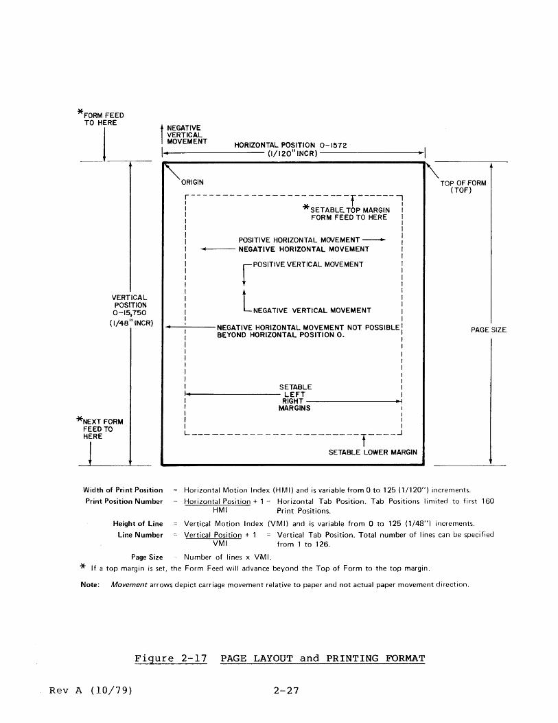
Figure 2-17 illustrates some of the points just described, as applied to a simple page layout.
2.4.4.2 Standard Formats
Either of two standard formats can be selected via the PITCH switch on the Operator Control Panel. These formats are summarized in Table 2-1.
2-26 Rev A (10/79)
*FORM FEED TO HERE
VERTICAL POSITION 0-15,750
( 1/48 II INCR)
*NEXT FORM FEED TO HERE
t NEGATIVE VERTICAL MOVEMENT HORIZONTAL POSITION 0-1572
\1--oI1Ir--------- (1/1201l
INCR) ----------..--1
'''-ORIGIN
r-----------------------r------, I I : *SETABLE. TOP MARGIN I I FORM FEED TO HERE I
I I I POSITIVE HORIZONTAL MOVEMENT -- l --- NEGATIVE HORIZONTAL MOVEMENT I r POSITIVE VERTICAL MOVEMENT
LNEGATIVE VERTICAL MOVEMENT
I I I I I I I I I I
..-----NEGATIVE HORIZONTAL MOVEMENT NOT POSSIBLE: BEYOND HORIZONTAL POSITION O. I I
I I I I
I I , I
I I I , I SETABLE I I~.~----------------- LEFT I I RIGHT -----------------j .. ~! I MARGINS I , I ,
L-----------------------t----~
SET ABLE LOWER MARGIN
I'" TOP OF FORM (TOF)
PAGE SIZE
Width of Print Position
Print Position Number
Horizontal Motion Index (HMI) and is variable from 0 to 125 (1/120") increments.
Horizontal Position + 1 = Horizontal Tab Position. Tab Positions limited to first 160
Height of line
Line Number
HMI Print Positions.
Vertical Motion Index (VMI) and is variable from 0 to 125 (1/48") increments.
Vertical Position + 1 VMI
Vertical Tab Position. Total number of lines can be specified from 1 to 126.
Page Size Number of lines x VMI.
* If a top margin is set, the Form Feed will advance beyond the Top of Form to the top margin.
Note: Movement arrows depict carriage movement relative to paper and not actual paper movement direction.
Figure 2-17 PAGE LAYOUT and PRINTING FORMAT
Rev A (10/79) 2-27

PITCH Switch
10 12
TABLE 2-1 STANDARD PRINTING FORMATS
Horizontal Spacing Vertical Spacing Charlin. Char/line HMI Lines/in. Lines/page
10 132 12 6 66 12 158 10 6 66
VMI
8 8
Whenever the PITCH switch is repositioned and an optional format has not been selected, the values listed in the table for the new position are used for horizontal and vertical spacing, and for lines per page.
Additional formats can be obtained by changing the HMI, VMI, or Lines Per Page. Such variable indexing overrides the PITCH switch function. Control may be restored to the PITCH switch by issuing the ESC S sequence.
2.4.4.3 Optional Formats (Variable Indexing)
Any of the three format factors can be altered by utilizing special escape (ESC) sequences. The ESC CR P (remote RESET) sequence may also be used here to cancel all optional format factors and return the Terminal to the format selected by the PITCH switch. Refer to subsection 3.2 for a detailed listing of all ESC sequences.
Execution of any of these sequences does not immediately alter horizontal or vertical position. It does, however, change subsequent operations by redefining the variable format factors. It is recommended that a Form Feed (FF) and an Absolute Tab (see subsection 2.4.4.10) to location 0 be performed prior to changing any format factors.
2.4.4.4 Variable HMI
The standard HMI can be altered in ASCII mode by executing the 3-character sequence ESC US (ASCII character), where the binary value of the selected ASCII character is one (1) greater than the number of 1/120 inch increments the carriage will move after printing a character or when spacing.
HMI = (ASCII character -1) x 1/120 inch
NUL and DEL characters cannot be used, therefore the mlnlmum HMI is o increments, and the maximum is 125 increments. See Appendix D-I to determine the ASCII character for the ESC sequence. An ESC S sequence will return control of HMI to the PITCH switch.
2.4.4.5 Variable VMI
The standard VMI can be altered in ASCII mode by executing the 3-character sequence ESC RS (ASCII character), where the binary value of the ASCII character is one (1) greater than the number of 1/48 inch increments the paper is to move for each line feed, negative line feed, etc. Minimum VMI is 0, maximum is 125. See Appendix D-l to determine the (ASCII character) for the ESC sequence.
2-28 Rev A (10/79)

VMI = (ASCII character - 1) x 1/48 inch
2.4.4.6 Lines Per Page
Lines per page is automatically set at 66 when the unit is initialized (restored on power up). The number of lines per page can be altered in ASCII mode by executing a 3-character sequence ESC FF (ASCII character) where the binary value of the ASCII character is equal to the number of lines per page desired. The minimum number of lines per page is 1, the maximum number is 126.
The following two formulas can be used to compute the desired number of lines per page:
* Lines Per Page = Number of Lines Per Inch x Page Size in Inches
48 * Number of Lines Per Inch = ------
VMI
Once the desired number of lines per page is known, use the information in Appendix D-2 to determine the (ASCII character) for the ESC sequence.
2.4.4.7 Forward/Backward Printing
All versions of the 1640/1650 Series are capable of printing forward (left to right) or backward (right to left) with equal ease. Backward printing is enabled by the sequence ESC 6, initiated either from the keyboard in local mode or thru the communications link in remote mode. The unit returns to normal forward printing upon receipt of either an ESC 5 sequence or a carriage return (CR) command.
During forward printing each character printed causes incremental carriage movement to the right. During backward printing, this motion is reversed with the carriage moving to the left. Note also that print data must be received by the unit logic in 'reverse order', and that the action resulting from the space and backspace commands is also reversed.
2.4.4.8 Print Suppression
Print suppression is initiated by the sequence ESC 7, and cancelled by a carriage return (CR) command. While this feature is enabled, all printable characters are replaced by spaces. Escape sequences and control characters are not affected.
Margin Placement I 2.4.4.9
Horizontal Margins: Both left and right margins can be adjusted by positioning the carriage to the desired print position, and then entering an ESC 9 or 0 (LEFT MAR or RIGHT MAR) sequence. Altering the left margin causes the carriage to return to the new print position setting following a carriage return (CR) command. Altering the right margin causes the audible alarm to sound for 1/2 second when typing continues beyond the new margin setting in the local mode.
Rev B (4/80) 2-29

The carriage can be moved to the left beyond the left margin by using either Absolute Horizontal Tab or Backspacing, when the margin is set at some print position other than 1.
A power on or a remote RESET operation will clear adjusted margins to print positions 0 and 1572.
vertical Margins: Both top and bottom vertical margins can be adjusted by first placing the paper in the top of form position, then moving the paper up with a series of LINE FEED operations to reach the desired top margin position. This "Top Margin" is then set by executing an ESC T sequence. Advancing the paper with LINE FEED operations to the desired "Bottom Margin" position, and then executing an ESC L sequence sets the bottom margin. The bottom margin must always be set below the upper margin, and both must be within the page size boundaries.
Top and bottom margins are reset to the top of form and bottom of page locations whenever page size is altered, or a remote RESET is received. They are also reset (or initialized) on power up, or upon receipt of a remote ESC C command in (ASCII) or (UC) PRE C command in 2741.
2.4.4.10 Tabbing
Two methods of tabbing are available for both horizontal and vertical motion. One method, called "Normal Tab", is similar to the traditional system used on typewriters in that tab stops are set at predetermined positions. The carriage or paper then moves to these positions sequentially on command. The second method is termed "Absolute Tab". This method is unique in that it does not require prior setting of tab stops. The carriage or paper is positioned directly to any one of 126 possible positions either horizontally or vertically from any other position. In the case of vertical tabbing, the paper should be moved "forward only", unless the unit is equipped with optional bidirectional paper handling accessories.
Both methods of tabbing provide horizontal and vertical positioning to standard print positions or lines. This makes it possible to print data out in any format desired without prior editing thru utilization of variable indexing. The method of tabbing to be used is specified by the character sequence used. The Horizontal Tab (HT) character or Vertical Tab (VT) character alone executes a Normal Tab operation. An ESC HT or ESC VT sequence, plus an ASCII character executes an Absolute Tab.
Normal Horizontal Tab: Horizontal tab stops can be set at any print position up to position 160 by positioning the carriage to the desired print position and executing an ESC SET HT sequence. Keeping in mind that tab stops can only be set at the first 160 print positions, the formula for determining a tab position is:
Horizontal Position Horizontal Tab Position (1-160) = ------------------- + 1
~I
2-30 Rev A (10/79)

A keyboard TAB command automatically Gauses the carriage to move to the next sequential tab stop. Should a TAB move be commanded with no tab stop having been set to the right of the present carriage position, the carriage will not move and the alarm will sound. Individual horizontal tab stops can be cleared by first positioning the carriage to that print position and then executing an ESC 8 (CLR HT) sequence. All tab stops,both horizontal and vertical can be cleared simultaneously by executing an ESC 2 (CLR TABS) sequence.
Absolute Horizontal Tab: In this mode the carriage can be positioned directly to any of the first 126 print positions without the need for prior setting of tab stops. Also, Absolute Tab Stops are not retained in memory and each stop must be commanded each time it is to be used. The command sequence for this is ESC HT (ASCII character), where the value of the (ASCII character) indicates the print position desired. See Appendix 0-3 to determine the (ASCII character) for the ESC sequence. The farthest left print position is considered to be binary location 1. The horizontal position at the completion of an Absolute Tab operation is computed as follows:
Horizontal position = (ASCII character - 1) x HMI
Normal Vertical Tab: Vertical tabs are set with reference to the Top Of Form position. This position, the first print line on the page, is reached by a keyboard FORM FEED command, followed by a manual adjustment of the paper location vertically to locate the paper in proper position. Vertical tab stops may then be set at any other line on the page by first moving the paper to the desired line by means of a series of LINE FEED commands, and then executing an ESC SET VT sequence. This is repeated for each desired tab stop. The location of the vertical tab stop is defined as follows:
Vertical position Vertical Tab Position = + I
~I
Once vertical tab stops are set, subsequent VT commands will cause the paper to be indexed upward to the next sequential vertical tab stop. If there are no more stops set between present print line and the end of the form, the paper will not move and the audible alarm will sound. Individual vertical tab stops cannot be cleared as can the horizontal tab stops. All tab stops, horizontal AND vertical are cleared simultaneously by executing the ESC 2 (CLR TABS) sequence.
Absolute Vertical Tab: In this mode the paper can be moved to any of the 126 possible lines on the page. Absolute Vertical Tab is initiated by executing the sequence ESC VT (ASCII character) where the value of the (ASCII character) chosen determines the number of the line to be reached. See Appendix 0-3 to determine the (ASCII character) for the ESC sequence. NUL and DEL are not used. The top print line on the page is assigned the binary value of 1, with each succeeding line down the page assigned the next higher number. Note that it is possible to tab beyond the end of the page if the total page line number is less than the maximum 126. The actual amount of paper movement is determined by a) the paper position before VT exe-
Rev A (10/79) 2-31

cution, b) the ASCII character used, and c) the Vertical Motion Index (VMI). The ultimate position reached is determined as follows:
Vertical position = (ASCII character - 1) x VMI
2.4.4.11 Line Feed
A LINE FEED command from the keyboard will cause the paper to be moved up one line (one VMI). A line feed will be accomplished automatically as a result of a Carriage Return operation when the AUTO LF switch is ON.
2.4.4.12 Form Feed
A FORM FEED command from the keyboard will cause the paper to be moved up to the first line of the next page, or to the top margin line if one has been set.
2.4.4.13 Graphics
An ESC 3 sequence received by the 1640/1650 Series issued either thru the keyboard or remotely will place the unit in the graphics mode. A carriage return command or an ESC 4 sequence will return the unit to normal operation. While in the graphics mode, carriage movement is not tied to character printing. Carriage movement is in 1/60 inch increments for space and backspace commands, and in response to tab commands. Also in the graphics mode paper feed movement in response to line feed commands is in 1/48 inch increments, while vertical tab, form feed, top of form and margin commands remain unchanged.
2.4.4.14 Two-Color Printing
Red/Black ribbon control is standard in all Diablo printers and terminals. Two-color printing can be achieved by installing a Diablo two-color ribbon cartridge. The mechanism initializes to print in the primary color (black). To print in the alternate color (red), execute an ESC A sequence. To return to the primary color, execute an ESC B sequence or a RESTORE sequence.
2.4.4.15 RESTORE (Initialization)
The 1640/1650 Series may be restored (or initialized) by executing an ESC CR P 3-character sequence. This command resets all the logic circuits, resets all program counters to zero, and sets the unit to operate as follows:
Normal print mode Forward print mode Print suppression OFF Print in primary color (black) HMI defined by PITCH switch VMI set to 8 (6 lines per inch) Lines/page set to 66 (page size of 528 x 1/48" = 11") All tabs cleared All margins cleared (horizontal to 0 and 1572 x 1/120")
(vertical to 0 and 528 x 1/48")
2-32 Rev A (10/79)

Send and print buffers cleared Vertical position cleared to 0 Carriage moved to Horizontal Position 0 Print Wheel moved to home position
Rev A (10/79) 2-33


SECTION 3
INTERFACE
3.1 GENERAL INFORMATION
The KSR Terminal has three modes of operation; Local, Remote ASCII, and optional Remote 2741. These modes are switch selectable by the operator. In the Local mode with the LOCAL key latched DOWN, the Terminal operates as a typewriter and cannot receive or transmit data. In either the Remote ASCII or Remote 2741 mode, the Terminal transmits and receives data thru a communications link, or interface. This section deals with that interface.
3.2 REMOTE ASCII (ANSI) MODE
(LOCAL switch UP, ANSI/2741 switch to ANSI)
In this mode, the Terminal responds to the control codes specified in EIA Standard RS-232-C, August, 1969. Codes can be generated and used internally using the keyboard. Codes can also be transmitted to and/or received from the interface for use by the connected system or the Terminal. In either condition, the codes are in addition to the ASCII character data transmitted and/or received.
The following list summarizes the control codes:
1. ACK: Transmitted over the communications link when an ETX is encountered in the print buffer. See "ETX" below.
2. BEL: Sounds the audible alarm (buzzer) for 1/2 second. Updates all summarized motion.
3. BS: Backspaces the carriage one print position (HMI) in normal mode, or 1/60 inch in graphics mode. Direction or movement reverses in the backward print mode.
4. CR: Causes a carriage return. If AUTO LF key is latched DOWN, also causes a line feed operation.
5. DCl: This signal can only follow a DC3 signal. When enabled by the DCl/DC3 ENABLE switch on the HPR04 PCB being set to ON, this signal is transmitted whenever the print buffer is within 64 characters of being empty, following the transmittal of a DC3 signal.
6. DC3: When enabled by the DCl/DC3 ENABLE switch on the HPR04 PCB being set to ON, this signal is transmitted whenever the print buffer is within 64 characters of being full.
NOTE: The DCl/DC3 protocol is an alternative to the ETX/ACK protocol. The purpose is to prevent buffer overflow and loss of data while maintaining a high throughput.
7. DEL: This signal is ignored by the 1640/1650 Series in all remote modes. In the local mode, this signal will cause the "?" character (1650) or "," character (1640) to be printed.
Rev B (4/80) 3-1

8. ENQ: Receipt of this signal initiates the automatic answer-back sequence "Here Is •• " if that option is installed.
9. ETX: This remotely generated signal is included at the end of a data string transmitted to the unit at a rate faster than the unit can print. The data string should be long enough to fill the print buffer. Upon finding the ETX in the buffer, the unit will immediately transmit an ACK signal to notify the sending system to send another data string. The ETX/ACK feature is enabled by the ETX/ACK ENABLE switch on the HPR04 PCB being set to ON.
NOTE: The ETX/ACK protocol is an alternative to the DCl/DC3 protocol. The purpose is to free the sending system from having to monitor the progress of the unit as it prints out the content of the print buffer.
10. ESC: This code is always received as the first character of a 2-or 3-character command sequence. ESC initializes the unit's logic to receive the characters next following, and preceding a CR, as commands and not print data. The following list summarizes the ESC command sequences:
Characters (1) (2) (3) ESC 0 ESC 1
ESC 2 ESC 3 ESC 4 ESC 5 ESC 6 ESC 7 ESC 8
ESC 9 ESC HT (n)
ESC LF ESC VT (n) ESC FF (n) ESC
ESC CR P ESC SYN (n)
Description of Command
Set Right Margin Set Horizontal Tab Stop at Current Carriage (print) position Clear ALL Horizontal and Vertical Tab Stops Graphics Mode ON (clear with CR) Graphics Mode OFF Forward Print Mode ON Backward Print Mode ON (clear with CR) Print Suppression ON (clear with CR) Clear Individual Horizontal Tab Stop at Current Carriage (print) position Set Left Margin Initiate Absolute Horizontal Tab to Position (n) Perform Negative Line Feed Initiate Absolute vertical Tab to Line (n) Set Lines Per Page to (n) Set vertical Tab stop at Current Paper Position Initiate Remote RESTORE (reset) Select Print Wheel Size (1650 Series only)
Where bits 5 and 6 of (n) are defined by the following: Bit 5 Bit 6 Print Wheel
o 0 Diablo 96 o 1 Rank Xerox 92 1 0 Rank Xerox 96 1 1 Xerox 88
See ASCII Code Chart in Appendix A for specific codes.
(continued)
3-2 Rev A (10/79)

I 11. FF:
12. HT:
13. LF:
ESC RS (n) ESC US (n) ESC S
ESC A ESC B ESC C ESC N ESC D ESC U ESC L
ESC T
ESC Y
ESC Z
ESC FF SOH ESC
Set Vertical Motion Index (VMI) to (n-l) Set Horizontal Motion Index (HMI) to (n-l) Set Horizontal Motion Index (HMI) by Pitch Switch Print in Secondary Color (red) Print in Primary Color (black) Clear Top and Bottom Margins Normal Carriage Settling Time Perform N€gative Half-Line Feed Perform Half-Line Feed Set Lower Page Margin at Current Paper Position Set Top Page Margin at Current Paper Position Print the Print Wheel Character under ASCII code 20(Hex) Print the Print Wheel Character under ASCII code 7F(Hex) LF FF ESC FF (n) Set Top of Form
(n = binary value of selected ASCII character. See Appendix D)
Initiates form feed to the top of the next form (or page), or to the top margin on the next form or page if one is set.
Initiates movement of the carriage to the next previously set Horizontal Tab Stop.
Initiates movement of the paper up one line (one VMI) • Movement changes to 1/48" per command in the Graphics mode, or two line feed operations if Double Line Feed is selected.
14. NUL: This signal is ignored by the 1640/1650 Series in all modes.
15. SP: Initiates movement of the carriage one print position (HMI) in normal mode.
16. VT: Initiates movement of the paper up to the next previously set Vertical Tab Stop.
NOTE: The ASCII codes outlined above also apply to Model 1640/1650 KSR Terminals in the local mode (LOCAL key latched DOWN).
3.3 REMOTE 2741 MODE (Option)
(LOCAL key UP, ANSI/2741 switch to 2741)
In this optional mode, the Terminal will respond to the IBM 2741 codes and protocol specified in "2740/2741 Communication Terminal Original Equipment Manufacturer's Information, GA27-3002-0", and "IBM Maintenance Library, 2740/2741 Theory of Operation, XY27-0013-4, January, 1973", both by IBM Corporation. These codes can be generated and used internally. The codes may also be transmitted to and received from a remote system. In either case, these codes are in addition to the PTTC/EBCD or Correspondence character data transmitted and received.
Rev B (4/80) 3-3

3.3.1 Control Codes
The following list summarizes the 2741 mode control codes:
1. BS:
2. BY:
3. EOA:
4. EOT:
5. HT:
6. LC:
7. LF:
8. NL:
Backspaces the carriage one print position.
Places the Terminal in the Print Inhibit (print suppression) Mode.
End Of Address code @, (IBM 8-2-1 code) • Prints n#" in PTTC/EBCD, or a "9" in CORRESpondence.
End Of Transmission code ©, (IBM C-8-4-2-l code) •
Initiates movement of the carriage to the next previously set Horizontal Tab Stop.
Places the Terminal in the Lowercase mode.
Initiates movement of the paper up one or two lines according to the setting of the DOUBLE LINE FEED key.
Initiates a simultaneous carriage return and line feed operation. The line feed portion responds to the setting of the DOUBLE LINE FEED key.
9. RES: Ends Print Inhibit (print suppression) mode.
10. SP: Initiates movement of the carriage one print position.
11. UC: Places the Terminal in the Uppercase mode.
3.3.2 2741 Mode Interface Line Control
In this mode, with the ANSI/2741 switch set to 2741, Interface Line Control becomes effective with power on and the LOCAL key released to its UP {remote} position.
3.3.2.1 Initi~ization
On power up, the Terminal is initialized in a control-receive state and automatically shifted to lowercase (if necessary). Following this the Terminal goes into the communicate-transmit state.
On switch over from local to remote mode, the Terminal goes immediately into the communicate-transmit state.
3.3.2.2 Transmit/Receive Interchange
In the 2741 mode, the unit operates in HALF-DUPLEX only, and ignores the setting of the DUPLEX/ON switch. In this configuration, the Terminal cannot receive and transmit simultaneously. The following discussion describes the code interchange by which the unit and its correspondent notify each other of their respective transmit/receive states.
3-4 Rev A (10/79)

Upon entering the communicate-transmit state, the Terminal transmits aQDcode to the interface, the PROCEED lamp glows, and the keyboard "unlocks". The operator may now key in any desired requests and/or text.
Transmission by the Terminal is ended by the operator activating either the BREAK switch or striking the (carriage) RETURN key. with this action, the Terminal reverts to the control-receive state and transmi ts a © code to the interface. The PROCEED lamp goes out,
SELECT LOWER CASE UNLOCK KEYBOARD
LIGHT PROCEED LAMP TRANSMIT@
1------------------------------------ ---------- ---1 I TRANSMIT TEXT MODE I I I I I I YES I I I I I J
I I I I I I I I I I I I
PRINT AND SEND CHARACTER
YES
YES TRANSMIT ©
SELECT LOWER CASE LOCK KEYBOARD
CLEAR !3ROCEED LAMP
r---- - ----- ------------------------------- - -- ~ I I I I I I
J RECEIVE CONTROL MODE YES I
r----------------------------------------- --~ I I I I I I I I I I I I I I
PRINT RECEIVED CHARACTER
SEND BREAK CLEAR QUEUES
I I I RECEIVE TEXT MODE I L ____________________________________________ ~
Figure 3-1 2741 LINE CONTROL
Rev A (10/79) 3-5

the DATA lamp glows, and the keyboard "locks up" to prevent attempts to make keyboard entries while the Terminal is receiving information from the interface. Attempted keyboard entries will cause the alarm to sound and the KEY lamp to glow for 1/4 second.
Upon comJ(letion of its transmission, the correspondent system transmi ts a (.£) code to the Terminal. Upon receipt of the © code, the Terminal switches back to the communicate-transmit state, the keyboard is "unlocked", the @ code is -transmi tted, the DATA lamp goes out, and the PROCEED lamp glows.
3.3.2.3 Interrupt
Receive Interrupt: This feature allows the operator to request that the correspondent system stop sending data, and is activated by pressing the BREAK switch. This causes the Terminal to transmit a 250 IDS
continuous space signal. The correspondent system mayor may not honor this request, but if it does, it stops transmission and sends the ~ code. The Terminal responds by entering the communicate-tr ansmi t state, tr ansmi t t i ng the @ code, and unlock i ng the keyboard.
Transmit Interrupt: This feature allows the correspondent system to interrupt Terminal transmission by transmitting a continuous space signal whose length is set by the system in increments of one character time and must be a minimum of one character time. Reception of this signal causes the Terminal to switch to the control-receive state. The ATTN lamp glows and the alarm sounds for 1/4 second.
Note that any data printed on a line during which an interrupt occurs may not be correct. For this reason, the interrupt should be considered a terminating condition that voids the entire line.
3.4 INPUT/OUTPUT GATES
3.4.1 Input Gates
The input impedance inside the unit is lk. The circuit is as shown in Figure 3-2.
3.4.2 Output Gates
The open collector circuit shown in Figure 3-3 is used to drive the output lines to the interface. In order to maintain impedance matching, collector resistance of 150 Ohms is recommended within the controll.er.
3.5 DATA TRANSFER TIMING
Figure 3-4 illustrates the signal timing relationships for the transfer of data into the 1640/1650 Series through the parallel data input lines.
3.6 RESTORE TIMING
Figure 3-5 illustrates the timing relationship for the RESTORE command.
3-6 Rev A (10/79)

7417
Figure 3-2 INPUT GATES Figure 3-3 OUTPUT GATES
DATA BIT 0-7
t-T'--1--~T,f -CHARACTER STROBE I I L
~T~ T4 ______ rT5~
Tl ~ 200NS T2 ~ 750NS T3 S; 450NS
-CHARACTER READY
T4 MIN~60,.. SEC TYP%200 pSEC MAX TIME TO PRINT OR PROCESS AVG = 25 MSEC T5 C! 0 NS
I
Figure 3-4 DATA TRANSFER TIMING
Rev A (10/79)
-RESTORE
TI 2 10 "SEC T2 S 60"SEC T3 S I SEC T45; 6SEC
Figure 3-5 RESTORE
3-7
I

3.7 DIAL UP
The Dial Up feature allows the 1640/1650 Series to be connected to a common carrier switched network. An appropriate modem is required. To establish connection with a correspondent system, the operator places the modern in its "talk" mode, dials the telephone number of the correspondent in the conventional manner, listens for an answer tone, then places the modern in its "data" mode. Connection is terminated either by switching the modem to its "talk" mode, or by turning off the power to the unit or the modem.
3.8 I/O SIGNALS - PARALLEL ASCII
3.8.1 -Character Strobe
~his active La signal transfers a character from the data lines to the printer. Characters should not be sent to the printer if the -Character Ready signal is HI.
3.8.2 -Character Ready
This active La signal indicates the printer is ready to accept another character on the data lines. This signal works with the -Character Strobe signal.
3.8.3 -Restore
This active LO signal causes the printer to perform a RESTORE sequence. The sequence consists of moving the carriage to the extre~e left margin (column 0), restoring the print wheel to its "home" position, and clearing all previous data format information (such as tab settings). This signal should not be used as a carriage return. Completion of the sequence is indicated by the -Printer Ready signal going from HI to La.
3.8.4 -Clear
This active La signal is generated by the printer any time it is clearing its internal logic. This action is short of the RESTORE sequence, and is intended for clearing keyboard logic and should not be used by printer controllers.
3.8.5 -Data Bits 0-7
When the keyboard is not used, these eight (8) active LO signals specify the character being sent to the printer. The character is gated and latched into printer logic by the -Character Strobe signal. The character is in the ASCII format and represents commands to the printer as well as data to be printed. The Most Significant Bit (MSB) will be ignored.
3.8.6 -Status Strobe
This active LO signal is used to send diagnostic status from the printer to the controller upon request.
3-8 Rev A (10/79)
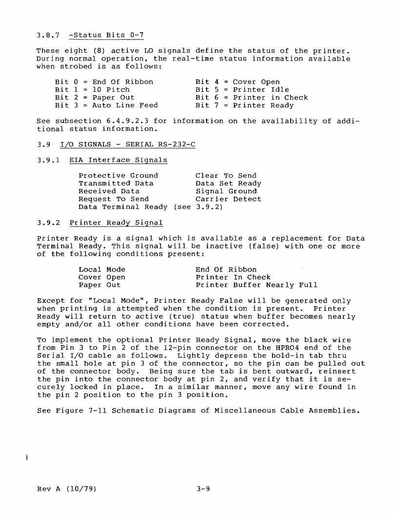
3.8.7 -Status Bits 0-7
These eight (8) active LO signals define the status of the printer. During normal operation, the real-time status information available when strobed is as follows:
Bit 0 = End Of Ribbon Bit 1 = 10 Pitch Bit 2 = Paper Out Bit 3 = Auto Line Feed
Bit 4 = Cover Open Bit 5 = Printer Idle Bit 6 = Printer in Check Bit 7 = Printer Ready
See subsection 6.4.9.2.3 for information on the availability of additional status information.
3.9 I/O SIGNALS - SERIAL RS-232-C
3.9.1 EIA Interface Signals
Clear To Send Data Set Ready Signal Ground Carrier Detect
Protective Ground Transmitted Data Received Data Request To Send Data Terminal Ready (see 3.9.2)
3.9.2 Printer Ready Signal
Printer Ready is a signal which is available as a replacement for Data Terminal Ready. This signal will be inactive (false) with one or more of the following conditions present:
Local Mode Cover Open Paper Out
End Of Ribbon Printer In Check Printer Buffer Nearly Full
Except for "Local Mode", Printer Ready False will be generated only when printing is attempted when the condition is present. Printer Ready will return to active (true) status when buffer becomes nearly empty and/or all other conditions have been corrected.
To implement the optional Printer Ready Signal, move the black wire from Pin 3 to Pin 2 of the l2-pin connector on the HPR04 end of the Serial I/O cable as follows. Lightly depress the hold-in tab thru the small hole at pin 3 of the connector, so the pin can be pulled out of the connector body. Being sure the tab is bent outward, reinsert the pin into the connector body at pin 2, and verify that it is securely locked in place. In a similar manner, move any wire found in the pin 2 position to the pin 3 position.
See Figure 7-11 Schematic Diagrams of Miscellaneous Cable Assemblies.
Rev A (10/79) 3-9


SECTION 4
PRINCIPLES OF OPERATION
4.1 GENERAL INFORMATION
The Diablo Series 1640/1650 machines are produced in three configurations; the basic mechanism, the RO version, and the KSR version. Each of these configur~tions can then be expanded by the addition of one or more options which include expanded memory, operator control panel, keyboard, cover sets, and paper handling accessories.
In its simplest form, the basic mechanism includes a modified Model 1345A HyType II printer for the 1640 Series or a Model 1355WP HyType II printer for the 1650 Series, with a Universal Interface circuit board configured for both serial and ASCII parallel data interchange.
In its most complex form, the 1640- or l650-KSR Terminal expands this to include a control panel, a keyboard, a cover set, expanded memory circuits with enhanced 2741 and word processing capability, plus the capability to interface with either serial or current loop systems. Note that the keyboard utilizes the ASCII parallel I/O port.
4.2 UNIVERSAL INTERFACE
The Universal Interface circuits perform a wide variety of tasks.
First, the actual interface must adapt the input/output signal levels to the TTL logic levels used inside the unit. The Serial Interface facility can accept the EIA Standard voltage swings of as much as +/- 25 volts (typically 15 volts maximum), and provides signals in the range of +/-7 to 12 volts to the modem.
Figure 4-1 illustrates the signal levels involved with the Serial Interface, and shows the fail-safe features of this facility. This feature provides for data protection should the modem lose power or become disconnected.
Figure 4-2 illustrates the signal levels and data format for the ASCII Serial Interface. The illustration shows the minimum spacing for both 10- and II-bit characters. Data output from the Terminal is via the Serial Interface when the keyboard is installed, and is asynchronous due to the large variation in character spacing.
Figure 4-3 illustrates an idealized representation of the data format found when the 2741 mode has been asserted. It differs from ASCII in that there are only six data bits with the MSB (most significant bit) first, only one stop bit, and with parity always odd.
Second, the Universal Interface processes incoming information and provides control signals to the carriage and print wheel drive circuits, and paper movement commands to the paper drive circuits.
Third, the Universal Interface processes data and transmits printer status information thru the appropriate output port.
Rev A (10/79) 4-1

OFF ON OFF MARK SPACE MARl(
+t.4V O--~~------~~------------------~--------~~---
-12V FAIL-SAFE OPERATION (CONTROL SIGNALS)
NORMAL OPERATION (RECEIVED DATA)
Figure 4-1 INPUT LINE SWITCHING LEVELS
CODE BITS
A. 110 BAUD, TIKJ STOP BITS.
STOP BITS
EARLIEST POINT AT WHICH NEXT CHARACTER MAY START_
I S1f~ I 2 I 3 I 4 I ~ I 6 I 7 I P I S~r I + (SPACoEvl 1010 Ftf R r-n ----.., ~ '- 0 - 0 L~J~ -+---1
_ (MARKlJ L.-________ U . _ 8. 300,600 OR 1200 BAUD, EARLIEST POINT AT WHICH NEXTi#
ONE STOP BIT. CHARACTER MAY START.
Figure 4-2 DATA FORMAT ON INTERFACE (ASCII)
START I I STOP BIT B A 8 4 2 C BIT
HSM:: j I-fo I r-
a a a a I I
----t-I I
-(MARK) I 134.5,300,600 OR 1200 BAUO. EARLIEST POINT AT WHICH NEXTi#
CHARACTER MAY START.
Figure 4-3 DATA FORMAT ON INTERFACE (2741)
4-2 Rev A (10/79)

4.3 THE PRINTER
A modified version* of the Diablo Model 1345A HyType II Printer forms the base of the 1640 Series. This serial inpact printer makes use of the processed output of the Universal Interface to position its carriage and print wheel, move paper, and to manipulate its ribbon and fire its print hammer to produce a high quality printout of the data received.
A modified version* of the Diablo Model 1355WP HyType II Printer forms the base of the 1650 Series. This serial impact printer makes use of the processed output of the Universal Interface to position its carriage and print wheel, move paper, and to manipulate its ribbon and fire its print hammer to produce the commanded printout in word processor quality.
* = Basic printer modifications include, but are not limited to; a different Motherboard, and the HPR04 Processor PCB which replaces both the Logic I and Logic II PCB's.
Rev A (10/79) 4-3


SECTION 5
MAINTENANCE
5.1 GENERAL INFORMATION
The Diablo Series 1640/1650 units are designed to greatly reduce maintenance and repair. unique electronic control systems require less than 20% of the mechanical assemblies usually found in machines of this type. The mechanical subsystems found in these units require a minimum of moving parts. This plus electronic components utilized well below their design limits has produced a unit with superior service characteristics.
5.2 PREVENTIVE MAINTENANCE
The recommended preventive maintenance is normal cleaning and inspection every 6 months or each 500 hours of power on operation. The machine will require cleaning and minimal lubrication at this time. Normal time for this preventive maintenance should not exceed 15 minutes.
5.3 MAINTENANCE PHILOSOPHY
A 3-level maintenance philosophy is recommended for the 1640/1650 Series.
5.3.1 Level One
Ribbon cartridge and print wheel change; surface cleaning and lubrication; adjustment of print impression and platen position controls; and minor assembly exchange of platens and paper cradle make up this level of maintenance.
5.3.2 Level Two
Due to the design of the 1640/1650 Series, machine subassembly and/or printed circuit board exchange is recommended for on-site failures. This level of maintenance also includes Level One items, plus unit replacement, and minor adjustments and alignments.
Spares on hand to support this level of maintenance activity should include at least one complete set of PCB's, subasemblies, and such miscellaneous components as recommended in the detailed maintence documentation.
5.3.3 Level Three
This is a Repair Depot and/or in-plant maintenance level, for the repair and/or refurbishment of assemblies, subassemblies, and PCB's.
Rev A (10/79) 5-1


SECTION 6
APPENDICES
6.1 GENERAL INFORMATION
This section describes the supplies, accessories and optional features currently available for each version of the 1640/1650 Series.
6.2 SUPPLIES
Refer to Diablo Publication No. 90007-XX Diablo Printer Supplies Catalog for a complete listing of all ribbons and print wheels currently available for use with the 1640/1650 Series.
6.3 ACCESSORIES
6.3.1 Paper Handling Accessories
The following paper handling accessories are applicable to certain versions of the 1640/1650 Series. For additional information on these items consult the Series 1640/1650 Parts Catalog, Diablo Publication No. 90414-XX and/or your Diablo Sales Representative. Where applicable, appropriate installation and operating instructions for these items are included in the 1640/1650 Series Operating Manuals, Diablo Publication No's 9040S-XX (1650) and 9041S-XX (1640).
Note that all of these accessories except platens require a Diablo or equivalent cover set.
6.3.1.1 Platens
1. Friction Feed Platen This platen is very similar to the rubber surfaced platens found in typewriters.
2. Pin Feed Platen This platen features a set of cam operated paper feed pins on each end of the roller. This rubber surfaced platen is available in several lengths from the factory.
3. Bidirectional Pin Feed Platen This platen features a set of dual cam operated paper feed pins on each end of the roller. The dual cam feature allows paper to be moved backward (down) as well as forward (up) without jamming. This platen is available in either of two lengths for 14.875" (377.83 mm) or 15" (381 mm) paper.
6.3.1.2 Forms Tractors
1. Unidirectional Forms Tractor This unit mounts on top of the printer cover where it engages the platen shaft for alignment and
I drive. It requires use of a friction feed platen. It is adjustable to any paper width from 2-3/4" (69.85 mm) to 14-1/2 11 (368.3 mm) maximum as measured between the pin feed drive holes.
2. Bidirectional Forms Tractor This unit mounts on top of the printer cover where it engages the platen shaft for alignment and drive. It requires use of a friction feed platen. It is adjustable to any paper
Rev B (4/80) 6-1

width from 2-3/4" (69.85 mm) to 14-1/2" (368.3 mm) maximum as measured I between the pin feed drive holes. It also features both upper and lower pin feed paper drives to enable feeding paper in either direction.
NOTE: Installation of the optional Forms Tractor Sound Cover will reduce maximum allowable paper width by 1/2" (12.7 mm) when used with the "thumb screw" version of the Forms Tractor.
6.3.1.3 Bottom Feed
All versions of the 1640/1650 Series can be configured to allow feeding of continuous (manifold) forms up thru the bottom of the mechanism. This feature requires use of either a Pin Feed Platen or Forms Tractor Accessory.
6.3.1.4 Sheet Feeders
1. Mechanical Front Feed Refer to Figure 2-3b, and to Diablo Publication No. 90421-XX Mechanical Front Feed Operation and Maintenance. This unit mounts on top of the printer cover. It engages the platen shaft for alignment, and is driven by a special gear mounted at the left end of the required friction feed platen roller. It feeds multipart forms, and single sheets of up to 48 Ib ledger stock into the printer, one item at a time. The inserted item extends down into a special bottom chute and out under the printer to allow printing within 1" of the top and at the very bottom before being ejected out the top. This accessory preempts use of the bottom feed option, and requires that the carriage be centered for each paper insertion.
2. Auto Front Feed Refer to Figure 2-3a, and to Diablo Publication No. 90422-XX Auto Front Feed Operation and Maintenance. This accessory consists of the Auto Front Feed unit, a special bidirectional forms tractor, interconnecting wiring, and the HyPlot, Feeder and Diagnostics option installed on the optional XMEM2 PCB. The resulting system feeds multipart forms, and single sheets of up to 48 Ib ledger stock in much the same manner as the Mechanical Front Feeder.
This unit operates independently of the l640/l650's paper drive system. It can be used in conjunction with continuous form (manifold) paper, with both auto feed and form feed controlled separately by the host system. An optional optical line finder version allows the feeder to sense a position marker preprinted in the left hand margin and automatically feed the form to a preset start position. Switch B12-4 on the XMEM2 PCB must be ON for this option.
The 1640/1650 enters the Front Feed Mode upon receipt of an ESC I sequence, and exits the mode upon receipt of either an ESC K sequence or a carriage return (CR) command. The ESC K sequence returns the 1640/ 1650 to its normal print mode as soon as the feeder has processed the last command character sent to it. Although this implies a possible departure from front feed mode during a command string, to return later for completion, this practice is not recommended. If the last command character sent initiated front feeder motion, the feeder's program will not recognize the exit sequence until the motion has been completed. Conversely, no motion commands will be honored when enter-
6-2 Rev B (4/80)

ing front feed mode while the 1640/1650 is printing until the last character entered has been printed. Exit from the front feed mode via a carriage return (CR) will always await completion of any front feed command sequence in process.
Upon entering front feed mode, the 1640/1650 will recognize ONLY the following Front Feed Mode commands *:
A - Step Forward (up) (144 steps per inch) B - Step Reverse (down) (144 steps per inch) C - Line Feed Forward (per Line Space setting)
- or -LF - Line Feed Forward (per Line Space setting) o - Automatic Insert. Unit will automatically insert a
form approximately 1 second after the form is placed in the input tray.
E - Line Feed Reverse (per Line Space setting) F - Find Last Line (Optical Line Finder option) G - Subscript (8 steps) H - Superscript (8 steps) I - Vertical Tab, associated with the optional Optical
Line Finder. In - Go (n) Lines Forward (000 - 170) Kn - Go (n) Lines Reverse (000 - 170) Ln - Go To Line (n) (001 - 255) Mn - Go (n) Steps Forward (000 - 999) Nn - Go (n) Steps Reverse (000 - 999) o - Insert Paper ** P - Eject Paper Forward (up) Q - Eject Paper Reverse (down) Rnnn - Set Format *** Sn - Set Line Spacing (001 - 127) Defaults to 6/inch T - Self Test U - Automatic Optical Line Finder insert (same as code "0"
above except uses Optical Line Finder option). V - Reset
(n = a 3 digit number as indicated)
* - Undefined characters received will be rejected and reported to the 1640/1650 as a PAPER OUT error. This will also cause the feeder to abort its current command but not exit the mode.
** - NOTE: The carriage MUST be centered on the sheet or form before paper insertion is attemptea:- The carriage card guide aids in proper control of the bottom edge of the sheet during the feed operation.
Upon receipt of the INSERT PAPER command (ASCII 0), the feeder will direct the 1640/1650 to move the carriage to center position before executing the command. Upon completion of the command, the feeder will direct the 1640/1650 to return the carriage to its former position.
If the printer should go into CHECK trying to center the carriage, the PRINTER and PAPER lamps will glow and action will stop to prevent a paper jam.
Rev A (10/79) 6-3

If the printing format has been set (SET FORMAT ASCII Rnnn) the paper will be positioned appropriately. If printing format has not been set, the paper will be positioned for printing to start at a point approximately 1" from the top edge. Note that as a sheet or form is inserted the feeder automatically jogs the form to align it before beginning the feed. This helps alleviate feed problems due to vertical misalignment.
*** - SET FORMAT (ASCII Rnnn) = 000 000 001 as stored in memory upon power on. The first three digits (000-170) control the upper margin. The second three digits (000-170) control the lower margin. The third three digits (001-255, nominal 090) are used with the optional Optical Line Finder, and describe the distance the paper or form must be fed after the Optical Line Finder senses a preprinted position marker.
SPECIAL FUNCTION KEYS: The Diablo keyboard includes two keys which are for forms control. They are LOAD FORM and EJECT FORM, and are located in the left-hand Control section. The LOAD FORM key will imitate the ASCII 0 command described above for the insertion of paper. The EJECT FORM key will imitate the ASCII P command for the ejection of paper forward (up). These keys are valid only during printer and/or front feed idle times. They will be ignored if they are pressed during execution of a command string in Front Feed Mode, and the KEY error lamp will glow. These keys will abort any unfinished Front Feed comrnand(s) stored by a carriage return (CR) command if pressed while the 1640/1650 is not currently in the Front Feed
Mode. I 3. HyFeed Sheet Feeder Refer to Figure 2-6, and to Diablo Publication No. 90420-XX HyFeed Sheet Feeder Operating and Maintenance. This unit mounts on top of the printer cover and engages the platen shaft for alignment and drive. It draws power from either the 1640/1650 or an optional external power supply. The unit permits storing, automatic feeding, and retaining of up to 200 sheets of 20 lb paper. Printing is possible from the extreme top to the extreme bottom of the page, or automatic positioning to a "top margin" starting point. This unit uses the friction feed platen, and requires that the 1640/1650 be configured with the XMEM2 PCB and appropriate options, or fitted with the HyFeed Interface Kit. Note that the carriage must be centered during each form feed (page transition).
6.3.2 Cover Sets
Diablo Cover Sets are available for both RO and KSR versions of the 1640/1650, configured for either regular or optional bottom feed. In addition, the RO style may also be ordered for use with or without the optional Operator Control Panel.
6.4 OPTIONS
The 1640/1650 may be configured with a series of hardware and firmware options which significantly increase its flexibility, capacity, and capability for special purpose application. These are as follows:
Keyboard Operator Control Panel Expanded Memory PCB Assembly
6-4 Rev B (4/80)

Internal Power Supply Current Loop Interface Word Processing Enhancements 2741 Option Mode/Enhancements HyPlot, Feeder, Diagnostics Expanded Buffer Keyboard Programmable "Here Is Baud Rate Option Mode
6.4.1 Diablo Keyboard
"
This assembly is optional with the Model 1640/1650 Printer Mechanisms, and standard with the Model l640/1650-KSR Terminals. It is not applicable to the Model l640/l650-RO Printers. The standard keyboard is discussed in subsection 2.4.3.2. Additional information on foreign language, APL, IBM 2741 Correspondence, and IBM 2741 PTTC/EBCD keyboards will be found in Appendix B.
Operator Control Panel I 6.4.2
This assembly is optional for use with the Model 1640/1650 Printer Mechanism. It is standard with Model l640/l650-RO Printers and Model l640/1650-KSR Terminals. Refer to subsection 2.4.2.2.
6.4.3 XMEM2 Expanded Memory PCB Assembly
This assembly is optional with all versions of the 1640/1650 Series. It is required for implementation of the Current Loop Interface option, the 2741 Mode options, and the Word Processor options. It is also required for addition of the controllable accessory paper handling units, for HyPlot, for external diagnostics,for expanding unit memory, and for the "Here Is" EAROM.
6.4.4 Internal Power Supply
This unit mounts inside the printer's main frame, and includes a cooling fan which mounts on the left-hand end of the frame, as shown in Figure 2-1. This power supply meets all the electrical power needs for the 1640/1650, and plugs directly into the Motherboard for distribution of power to the various circuits. AC input power options are 90-l30V/180-260V, 47-63 Hz, with power controllable either from the host system or the optional Operator Control Panel.
6.4.5 Current Loop Interface
The Current Loop Interface option is described in subsection 1.1.2.3. This option consists of components added to the XMEM2 PCB and a customer supplied interconnecting cable (see subsection 2.2.4) installed between the current loop output on the XMEM2 PCB and the serial input on the HPR04 Universal Interface PCB. Jumpers and resistors (user supplied) are used on the XMEM2 PCB to select 20ma or 60ma/passive or active/half- or full-duplex operation as described in subsection 4.4 of the Series 1640/1650 Maintenance Manual #904l3-XX. The speed of the current loop interface is established by the speed seJected for the Serial Interface, as described in subsection 1.1.2.1.
Rev B (4/80) 6-5

6.4.6 Word Processing Enhancements
The 1650 Word Processing Enhancements option consists of a number of features that make the development of word processing software much simpler. This option consists of components added to the XMEM2 PCB. Some features of this option require the Operator Control Panel or a keyboard, while others require memory storage while being performed. Those which require memory are:
Line Edit Auto Justify
Auto Line Center Auto Underscore
6.4.6.1 Proportional Space Printing
Use of Proportional Space (PS) print wheels on the 1640/1650 is eased by this feature of the Word Processing Enhancements option. A table of PS unit values is retained in the memory of the 1640/1650. These PS unit values represent one-half of the width required by each proportionally spaced character. The letter "V", for example, has a PS value of 6, which is half of the 12/120" spacing a "V" requires. Carriage movement is calculated by adding the PS unit value of the character just printed to the PS unit value of the character about to be printed. Thus, if the character Hi" is to follow a "V", the carriage must move 9/120" before printing the Hi". This is the sum of the PS unit values of the Hi" (3) and the "V" (6). Tables of PS unit values for most standard characters on both metal and plastic print wheels are contained in Appendix E. Note from the Tables that the PS unit values for many characters on the metal print wheels differ from those on the plastic print wheels.
Proportionally spaced printing requires use of a Proportional Space print wheel. See Diablo Publication No. 90007-XX Diablo Printer Supplies Catalog.
When the Operator Control Panel is installed in a 1640/1650, one of the switches under the access cover (PROP SPACE, second from the right) is used by the operator when a PS print wheel is installed (switch ON) or removed (switch OFF).
In the absence of the Operator Control Panel, proportionally spaced printing can be enabled by supplying the sequence ESC P to the 1640/ 1650 thru its communications interface. Proportionally spaced printing can also be turned off in this same manner using the sequence ESC Q. These commands can also be used with units equipped with the control panel. In this case, remote PS commands override the setting of the PROP SPACE switch. Control can be returned to the switch by issuing (ESC S).
Proportionally spaced printing is not affected by the execution of the ESC X sequence which turns off all other Word Processing Enhancement Option functions.
There are times when certain data is to be printed nonproportionally spaced, even though a PS print wheel is being used in the 1640/1650. For example, the display from a Video Terminal is to be printed to illustrate a document; if it is printed proportionally spaced, the
6-6 Rev A (10/79)

columnar alignment of the information would be lost. Issue the ESC Q sequence to exit proportional space printing, then execute an ESC US DLE sequence to set the Horizontal Motion Index (HMI) to 15; this is adequate to print all characters on the PS print wheel without any characters touching. When the nonproportionally spaced printing has been completed, revert to normal HMI by executing the ESC S sequence, and return to proportionally space printing by executing the ESC P sequence.
Note that all numeric characters have the same PS unit value (5). This allows numeric data to be printed aligned in columnar form without having to turn off proportional space printing. The starting position of the columns can be established by setting a tab at that position, and tabbing to it, or by using the absolute horizontal tab to move to the starting position (see subsection 2.4.4.10). Be sure that HMI has the same value prior to each movement to the beginning of the column, if you are altering the value of HMI during the printing of each line, to be sure that the starting position does not change.
Proportionally spaced printing can be accomplished without using the Word Processing Enhancements Option by controlling carriage movement under software control. Maintain a table of PS unit values for each character to be printed; scan the line of characters and calculate the HMI value that is required to move the carriage for each character based on the character preceding it; send the data to the 1640/1650 in the sequence:
ESC US (ASCII char acter for HMI) (char acter to be pr in ted)
for each character that is to be printed. Note that four characters are sent to the 1640/1650 for each that is printed. To drive the 1640/1650 at rated speed (maximum of 40 cps) a communication link of over 1600 Baud is required (40 cps x 10 bits per byte x 4 transmitted characters per printed character).
6.4.6.2 Offset Selection (Auto Prop. Spacing)
The normal way to change character spacing is to adjust HMI. However, for proportionally spaced printing, HMI is ignored and table values are used. Thus, to add or subtract a constant to each table size, the sequence ESC DC1(byte) should be used. The value of the "byte" character is added to each table size value, or HMI if it is controlling size, as well as to the space character. This continues until another ESC DCl(byte) sequence is received, or until offset is cleared by a carriage return (CR) or the sequence ESC X.
The byte character is defined as follows:
Bits 1-6 Bit 7
Size of offset Sign of offset
(64 uni ts maximum) (one uni t = 1/120") (1 = negative)
I If a negative offset (smaller character size) is desired, bit 7 should be set. If the resulting character size is zero or less, no carriage movement will occur. Note that because NUL and DEL cannot pass thru the serial receiver, positive offset values range from 1 thru 64, negative values range from 0 thru 63. Refer to Appendix A-I.
Rev B (4/80) 6-7

6.4.6.3 Auto Underscore
Automatic underscoring is initiated by the sequence ESC E. The present carriage position is stored in memory as the start location. When the end position is reached, the carriage will return to the start location and underscore the area between it and the end position. The printed underscore characters will overlap and the ribbon advance will increase to prevent fading.
The end position is defined as the carriage position when one of the following events occur.
ESC R - The underscoring will occur and the 1640/1650 will exit the Auto Underscore mode.
CR - The underscoring will occur and the start location set equal to the left margin.
LF - The underscoring will occur and the start location set equal to the present carriage position.
No underscoring will occur if the area between the start and end locations is not positive or if the sequence ESC X is received. Auto Underscore is cancelled by either sequence ESC R or ESC X.
6.4.6.4 Bold Overprint
Bold overprint is initiated by the sequence ESC O. Subsequent printable characters are struck twice with no intervening carriage motion. The normal ribbon advance occurs between character strikes. A carriage return (CR) or either of the sequences ESC & or ESC X will cause the 1640/1650 to exit the bold overprint mode.
NOTE: Bold Overprint and Shadow Print are mutually exclusive modes.
6.4.6.5 Shadow Print
Shadow print is initiated by the sequence ESC W. Subsequent printable characters are struck twice with 1/120" of carriage movement and normal ribbon advance between character strikes. This does not change the HMI or table size value for that character. Increased carriage settling time may provide improved Shadow Print quality on some units. A carriage return (CR) or either of the sequences ESC & or ESC X will cause the 1640/1650 to exit the shadow print mode.
6.4.6.6 Carriage Settling Time
The carriage settling time can be increased to 20 msec by issuing the sequence ESC %. This provides more time for mechanical vibrations to damp out before printing to improve print quality, at a small sacrifice in print speed. The sequence ESC N will restore the normal carriage settling time.
6.4.6.7 Half-Unit Backspace
The sequence ESC BS will produce a 1/120" backspace movement of the carriage.
6-8 Rev A (10/79)

6.4.6.8 Program Mode
Program mode provides user control of spoke position, hammer energy, and ribbon advance. This allows the use of special print wheels without modifications to the 1640/1650. In Program Mode, two characters are sent for each character to be printed. The first character selects the print wheel spoke, the second establishes the hammer energy and ribbon advance. See Appendix E for a table of Hammer Energy and Ribbon Advance units.
Spacing is controlled by HMI plus offset. If the 1640/1650 is in proportional space mode, spacing is controlled by the ribbon advance (move RA, print, move RA) plus offset.
Program mode is initiated by the sequence ESC SO M. It is turned off by either the control character SI or the sequence ESC X. If the sequence for Auto Justify or for Auto Center is received, the 1640/ 1650 will exit program mode and enter the requested mode.
NOTE: MARG CONT and LINE EDIT keys do not function in Program Mode.
6.4.6.8.1 Spoke position Data (first character)
The first character received is tested to dete£mine if it is a control character or a spoke position character. If it is a control character, the normal processing of control characters will occur. If it is not a control character, it is assumed to be a spoke position character (the second character will not be tested for control character parameters). The non-control first character (the one to be printed) is selected in terms of the electrical equivalent of its physical print wheel position as follows:
Electrical Spoke Position number (per Appendix C) + 32 = n
where n is the decimal value of the ASCII character to be sent (see Appendix A Figure A-I). Note that only spokes 1 thru 94 can be distinguished from control characters. However, spokes 0 and 95 can be accessed by an ESC Y or ESC Z sequence respectively, followed by the second and third characters.
6.4.6.8.2 Hammer Energy/Ribbon Advance Data (second character)
The second character contains 4 bits (0-3) for ribbon advance and 3 bits (4-6) for hammer energy. This provides 16 different size ribbon advances (0 to 15 steps) and 8 different hammer energy levels (0 to 7). The hammer energy level definitions are as follows:
Level 0 - Select spoke 0, do not fire hammer Level 1 - Lowest hammer energy Level 2 - Low hammer energy Level 3 - High hammer energy Level 4 - Highest hammer energy Level 5 - Above Level 4 (maximum hammer energy) Level 6 - Hammer energy between Levels 1 and 2 Level 7 - Hammer energy between Levels 3 and 4
Rev A (10/79) 6-9

Caution should be exercised when using Level 5, as it will cause higher than normal print wheel wear. Refer to Appendix C and E for more information.
6.4.6.9 Cancel Word Processing Options
The sequence ESC X will cancel the following Word Processing modes:
Auto Underscore Shadow Print Offset Selection
Auto Center
Bold Overprint Program Mode Auto Justify
Proportional space mode and increased carriage settling time are not cancelled by ESC X.
6.4.6.10 Auto Center
Auto line centering is initiated by the sequence ESC =. Subsequent data is stored in a memory buffer until a carriage return (CR) or a line feed (LF) command is received. The data is then printed centered between the margins and the 1640/1650 exits the auto center mode. Auto Center allows the line to extend beyond the left and right margins. If Auto Justify was enabled when Auto Center was entered, Auto Center will have precedence for that line only. The sequence ESC X will clear Auto Center without performing any printing.
6.4.6.11 Auto Justify
Automatic margin justification is initiated by the sequence ESC M. Subsequent data is stored in a memory buffer until a carriage return (CR) or a line feed (LF) command is received. The data is then printed justified between the left and right margins. Auto Justify remains enabled until the sequence ESC X is received. The 1640/1650 then exits the mode without performing any printing.
Auto Justify functions in fixed pitch or proportional space mode. Up to 256 data characters may be included in a line; additional characters cause the OVERFLOW lamp to glow, and data is destroyed. Note that all communication protocols still function normally. If the LINE EDIT key is on, data from the keyboard will also be printed as it is stored.
Auto Justify begins its justification calculations from the position of the first printable character after the carriage return (CR), line feed (LF), or ESC M sequence. This allows unjustified leading spaces or tabs and allows partial line justification. Auto Justify calculates the number of 1/120" offset units needed to fill out or to condense the line so that it will fit exactly between the first printable character and the right margin. The offset units are then applied, first to the word spaces, and then to the character spaces after the word spaces reach 150% of their normal size. If the offset added to the character spaces exceeds 7 units, the line is printed unjustified. Offset units are added from left to right on odd lines and from right to left on even lines.
6-10 Rev A (10/79)

6.4.6.12 Line Edit
Line edit mode is selected by the LINE EDIT key in the keyboard control section. Line editing is a means of verifying and correcting data before it is transmitted. Line edit mode prints and stores keyboard data as it is entered without transmitting the data. While the line data is in the buffer, depressing the DEL key will erase the last character and backspace the carriage, thus allowing for corrections. When a carriage return (CR) or line feed (LF) character is entered, the stored data will be transmitted. This transmitted data will also be printed after a local carriage return-line feed has been performed. LINE EDIT key transitions always clear the print buffer. Release of the key also causes a local carriage return-line feed.
Data may be received while in the Line Edit mode only when the buffer has no keyboard data entered. If the memory buffer is not empty, received data will be rejected, the ATTENTION lamp will glow, and the alarm will sound. Only the following keyboard entries will empty the buffer; carriage return (CR), line feed (LF), or transitions of the LINE EDIT key.
NOTE: The control panel FF and LF switches are treated as keyboard data when the LINE EDIT key is on and keyboard data has been entered. Using the BREAK switch may disrupt LINE EDIT data.
6.4.6.13 Margin Control
Margin control mode is selected by the MARG CaNT key in the keyboard control section. Margin control is a means of increasing typing throughput by providing automatic carriage returns at appropriate line endings. A carriage return and line feed are provided on the first space or hyphen after entering a "hot zone" of five characters before the right margin, when the "AUTO CR" switch is on. The alarm will sound when the "hot zone" is entered instead of when the right margin is crossed. If in remote, the carriage return and line feed are transmitted. Auto Line Feed and Double Line Feed functions remain the same as with a normal carriage return. The carriage return provided by Margin Control does not clear Bold or Shadow Print modes. It will cause Auto Underscore to operate the same as it does for a normal CR command.
6.4.7 2741 Option Mode/Enhancements
2741 mode operation is an optional feature. Because of the nature of its communications requirements, this option is described in Interface subsection 3.3. 2741 Enhancement is a switch selectable feature which adds to normal 2741 operation. It expands the 2741 mode, as described in subsection 3.3, to include all ASCII functions when the HPR04's ENHANCED 2741 switch is set to ON. The following control codes then become effective:
1. BS: Backspaces the carriage one print position (HMI) in the normal mode, 1/60" in the graphics mode. Direction of carriage movement reverses in the backward print mode.
2. BY: Places the 1640/1650 in the print inhibit (suppression) mode. (cleared by RES)
Rev B (4/80) 6-11

3. DEL: This signal is ignored by the 1640/1650 in all remote modes. It can be used as a buffer or 'sluff' character. In the LOCAL mode, the DEL character will cause printing of the print wheel character under ASCII code 7F(Hex).
4. EOA: End Of Address code @. See subsection 3.3.1.
S. EOT: End Of Transmission code©. See subsection 3.3.1.
6. HT: Initiates movement of the carriage to the next previously set Horizontal Tab Stop.
7. LC: Places the 1640/1650 in the Lowercase mode.
8. LF: Initiates movement of the paper up one or two lines according to the setting of the DBL LF key. The movement is changed to one or two increments of 1/48" each in graphics mode.
9. NL: Initiates a simultaneous carriage return and line feed operation. The line feed portion responds to the setting of the DBL LF key_
10. PF: Causes the alarm to sound for 1/4 second.
11. PRE: This code is always received as the first character of a 2-or 3-character command sequence. PRE initializes the 1650 logic in the Enhanced 2741 Mode to receive the next 2 or 3 characters preceding a CR as a command and not as print data. The following list summarizes the PRE command sequences:
Command Characters (1) ( 2) (3) PRE 0 PRE 1
PRE 2
PRE 3 PRE 4 PRE 5 PRE 6 PRE 7 PRE 8
PRE 9 PRE HT (n)
PRE UNl PRE UN2 (n)
PRE UN3 (n) PRE (hyphen)
Command Description
Set Right Margin Set Horizontal Tab Stop at current carriage (print) position
Clear all Horizontal and Vertical Tab Stops
Graphics Mode ON Graphics Mode OFF (clear also with NL) Forward Print ON Backward Print ON (clear with NL) Print Suppression ON (clear with NL) Clear individual Horizontal Tab Stop at current carriage (print) position
Set Left Margin Initiate Absolute Horizontal Tab to print position (2n + 1)
Perform negative line feed Initiate Absolute vertical Tab to line
(2n + 1) Set Lines Per Page = (2n) Set Vertical Tab Stop at current paper position
6-12 Rev A (10/79)

PRE SYN (n)
PRE PN (n) PRE S PRE A PRE B PRE C PRE N PRE D PRE U PRE L
PRE T
PRE Y
PRE Z
PRE LF PRE NL (n)
Select Print Wheel Size if no control panel installed Where bits 5 and 6 of (n) are defined by the following: Bit 5 Bit 6 Print Wheel
o 0 Diablo 96 n 1 Rank Xerox 92 1 0 Rank Xerox 96 1 1 Xerox 88
See ASCII Code Chart in Appendix A for specific codes.
Set Horizontal Motion Index (HMI) to (n) Set HMI to PITCH switch Print in secondary color (red) Print in primary color (black) Clear Upper and Lower Margins Normal SettLing Time Perform Negative Half-line Feed Perform Half-line Feed Set Lower Page Margin at current paper position
Set Upper Page Margin at current paper position
Print the print wheel character under ASCII code 20(Hex}
Print the print wheel character under ASCII code 7F(Hex)
Form Feed to Top of (next) Form Initiate Remote RESTORE (reset)
12. RES: Ends print inhibit (suppression) mode when initiated by a BY code.
13. SP: Initiates movement of the carriage one print position in normal mode, one 1/60" increment in graphics mode. Direction of movement reverses in backward print mode.
14. UC: Places the 1640/1650 in the Uppercase mode.
15. UN2: Initiates movement of the paper up to the next previously set Vertical Tab Stop.
16. UN3: Initiates Form Feed to the top of the next form, or to the upper margin if one is set.
NOTE: (n) = 2741 character whose decimal value is equal to the decimal position, number of lines, or increments. See Appendix D-4.
6.4.8 HyPlot, Feeder, Diagnostics
This firmware supports HyPlot Vector Plotting, the Diablo Auto Front Feed and HyFeed paper handling accessories and External (remote) Diagnostics.
Rev A (10/79) 6-13

6.4.8.1 HyPlot Vector Plotting
The 1640/1650 HyPlot Vector Plotting option provides the capability to produce graphs and other vector designs in a manner considerably faster than the standard graphics mode. The vector plotting commands closely resemble those employed by various graphics plotters, which results in the higher speed.
In the HyPlot mode, the printing position may be moved thru a combination of carriage moves (X) and/or paper feed moves (Y) using the smallest increments available. These moves are possible between any two print positions on a currently defined page using a command of no more than six bytes. Any ASCII character may be used as the plot character, or the system allowed to default to use of the period (.). Plot resolution may be varied over a wide range to accommodate either high throughput or high density plotting using either absolute or relative vectors.
The HyPlot commands are:
ESC G
ESC G BEL
ESC V
ESC V BEL
ESC . character
ESC , h v
ESC A
ESC B
ESC 4 (or CR)
Enter HYPLOT ABSOLUTE mode. All vectors are interpreted as absolute locations. Draw all vectors except the first, which is a move only. Same as ESC G except all vectors are to be drawn, including the first.
Same as ESC G except all vectors include a sign byte and are treated as RELATIVE coordinates.
Same as ESC G BEL except that all vectors include a sign byte and are treated as relative coordinates Change plot character to "character". Space = no print but execute plotting motion; ESC Y = Print Wheel character under ASCII
code 20(Hex); ESC Z = Print Wheel character under ASCII
code 7F(Hex).
"h" refers to horizontal resolution in increments of 1/120". Default value = 2. "v" refers to vertical resolution in increments of 1/48". Default value = 1. If both horizontal and vertical resolution = 0 then only the starting and ending points of a vector will be plotted. Both "h" and "v" may assume values between 0 and 31. Refer to Table 0-2, the portion "SPACE" thru "?", where "SPACE"=O and "?"=31.
Ribbon down, print in red.
Ribbon up, print in black.
Exit HyPlot mode.
6-14 Rev A .(10/79)

A HyPlot vector consists of one to six ASCII characters in the following sequence:
1 SIGN -2 HIY 3 XLOY -
4 LOY 5 ,HIX 6 LOX
Needed only in relative mode 5 most significant bits of Y coordinate 2 least significant bits of both X and Y coordinates 5 intermediate bits of Y 5 most significant bits of X coordinate -5 intermediate bits of X
A vector may contain less than six bytes if some of them are unchanged from the previous vector, or if the absolute mode is selected.
Table 6-1 illustrates the format of the data in vector bytes, while Table 6-2 illustrates the bytes required to change the various fields of data.
BYTE 7
SIGN 0 HIY 0
Table 6-1 VECTOR DATA FORMAT
ASCII CHARACTER 6 5 4
1 x T x I 3
x I 1 5 MSBs of Y
2 1 Y NEG I X NEG
XLOY 1 1 0 -r 2 LSBs of Y I 2 LSBs of X LOY 1 1 5 Intermediate bits of Y HIX 0 1 5 MSBs of X LOX 1 0 5 Intermediate bits of X
Table 6-2 DATA BYTE CHANGE REQUIREMENTS - ABSOLUTE MODE ONLY
CHANGED BYTES THAT MUST BE SENT BYTE HIY XLOY LOY HIX LOX
HIY • • XLOY • • • LOY • • HIX • • • LOX •
RETRANSMIT PREVIOUS VECTOR - •
NOTES: 1. A HYPLOT vector consists of one to six ASCII characters which must
always be in the sequence stated. 2. The SIGN character must always be sent in RELATIVE mode. 3. The SIGN character must NOT be sent in ABSOLUTE mode. 4. If the 5 intermediate bits of Y (LOY) are all ones (I), the se
quence ESC Z should be used to prevent ASCII DEL from being used as a data byte.
5. 1640/1650 HYPLOT is not designed to operate with 2741 protocol. 6. Refer to Table 6-1. "x" = don't care. 7. Refer to Table 6-1. Negative movement if 1, positive if o. 8. Vector plot origin is located at vector "SP , , SP @". 9. In relative mode, Table 6-2 is invalid; all bytes must be resent.
Rev A (10/79) 6-15

6.4.8.2 Paper Feeder Options
This portion of the firmware supports the operation of the accessory paper feed equipment described in subsection 6.3.1.4.
6.4.8.3 External (Remote) Diagnostics
The remote diagnostics option allows the interrogation of machine parameters and status, and the initiation of a self test sequence to be performed thru both the serial and parallel interfaces.
6.4.8.3.1 Diagnostic Commands
The following diagnostic commands are included in this option:
ESC SUB I Initialize the printer ESC SUB 1 Request status word 1 ESC SUB 2 Request status word 2 ESC SUB 3 Request status word 3 ESC SUB 4 Request status word 4 ESC SUB 5 Request status word 5 ESC SUB 6 Request status word 6 ESC SUB SO Perform selt-test ESC SUB U Enter user (programmable) test mode ESC SUB W (n) Enter wrap-around (echo) test mode ESC SUB X Exit test mode DEL Error correct backspace (user test mode only) STX Print buffer once (user test mode only) SOH Print buffer repeatedly (user test mode only)
6.4.8.3.2 Interface Protocol
Status information is not supplied to the interface of any keyboard equipped Series 1640/1650 while it is in the LOCAL mode. All diagnostic commands are processed immediately when received and are not queued. This means all status reported will be the status present at the time the command was received. Only the low 7 bits (bits 0 thru 6) of a status byte are significant. Their equivalent value may range from 0 to 127. The MSB (bit 7) will be a PARITY bit on the serial interface and PRINTER READY on the parallel interface. The one exception is in WRAP-AROUND mode, where the MSB (bit 7) sent thru the parallel interface will be that received from the host computer.
Serial Interface
All commands that generate a response from the 1640/1650 will send back a status byte to the host computer preceded by a STX character when sent thru the serial interface. The rules for ETX/ACK and OCl/DC3 protocols are applicable and should be used for sending status requests to the 1640/1650.
Parallel Interface
Parallel interface timing for a status request is shown in Figure 6-1. The status will always be sent thru the parallel interface with a corresponding status strobe. The requested status is available at the
6-16 Rev A (10/79)

leading edge of the status strobe and will remain on the interface until another character is accepted from the host computer, indicating that the status has been received by the host system. Any status on the interface from the time the third character of the sequence is sent until the leading edge of -STATUS STROBE is received should be ignored. The parallel interface will always default to a STATUS 1 condition after power up, a printer initialize sequence, or within 100 usec of accepting another character thru the interface (-CHAR ROY = LO after receipt of a character). At this time -STATUS STROBE will go HI (false) to indicate that the default status is now on the interface bus.
6.4.8.3.3 Diagnostic Command Definitions
ESC SUB I This command will cause the 1640/1650 to unconditionally execute an initialize sequence regardless of any error conditions that may exist within the printer. Unlike the corresponding sequence ESC CR P, this command is executed immediately when received. The 1640/ 1650 will default to the conditions that exist at power up. This command should be preceded by a nonprinting character to cause the 1640/1650 to abort any multiple character sequence in progress.
WRAP TEST
STATUS OR SELF-TEST
ESC
(x)
-CHAR STROBE U -CHAR ROY
-STATUS STROBE
SUB
0 U) LLI
U
U
i=_
W
U)ct
~ti (n) I 0 REPEATS FOR WRAP (n)
m ~ U)
~ ~ TEST UNTIL EXITED LLla::
CD~~ 0-1. rn (x)
U u U u
-STATUS 0-7 STATUS I XREQ STATUSI/
______ --J 1TJ.ft T2 ;})
r,.
T I MIN~50JJSEC ---I MAX SI SEC (SELF-TEST)
AVG. :::150pSEC
T2 5pSEC T4 -----I ..
T3 IOO)1SEC
T4= TIME REQUESTED STATUS AVAILABLE DETERMINED BY HOST COMPUTER.
(n)= WRAP DATA (x)= DON'T CARE
Figure 6-1
(n) (n)
(x) (x)
u
XSTATUSI
-lT3l-
PARALLEL INTERFACE RESPONSE TO STATUS REQUEST, SELF-TEST and WRAP TEST
Rev A (10/79) 6-17

ESC SUB 1 This command will cause the 1640/1650 to send STATUS 1 to the interface. The bit definitions for STATUS 1 are:
0 End Of Ribbon 4 Cover Open Switch 1 10 Pitch 5 Printer Idle (no motion and 2 Paper Out Switch queue empty) 3 Auto Line Feed Switch {O if 6 Printer in Check
no panel} 7 **Parity Bit or Printer Rdy**
ESC SUB 2 This command will cause the 1640/1650 to send STATUS 2 thru the interface. The bit definitions for STATUS 2 are:
o 1 2 3
Control Panel Option Diablo Keyboard Option Plastic Print Wheel Mode Serial Interface Option
4 5 6 7
Always 0 Always 0 Always 0 **Parity Bit or Printer Rdy**
ESC SUB 3 This command will cause the 1640/1650 to send STATUS 3 thru the interface. The bit definitions for STATUS 3 are:
o 1 2 3 4
5
6 7
Enhanced 2741 Switch ETX/ACK Enable Switch OCl/DC3 Enable Switch Correspondence Switch 92 Character Switch
(not used on 1640) 96 Character Switch
(not used on 1640) Scroll Switch **Parity Bit or Printer
(always 0 if no panel) (always 1 if no panel)
(always 0 if no panel) (set by ESC sequence if no panel)
(set by ESC sequence if no panel)
(always 0 if no panel) Rdy**
ESC SUB 4 This command will cause the 1640/1650 to send STATUS 4 thru the interface. The bit definitions for STATUS 4 are:
0 Full-Duplex Switch 1 Proportional Space Switch (always 0 if no panel) 2 APL Mode Switch (always 0 if no panel) 3 ASCII Mode Switch (always 0 if no panel) 4 Auto Carriage Return Switch (always 0 if no panel) 5 Paper Out Defeat Switch (always 0 if no panel) 6 Always 0 7 **Parity Bit or Printer Rdy**
ESC SUB 5 This command will cause the 1640/1650 to send STATUS 5 thru the interface. The bit definitions for STATUS 5 are:
o 1 2 3
Attention (break) received Print Wheel in check Carriage in Check Always 0
4 5 6 7
6-18
Print Buffer Overflow Always 0 Parity Error **Parity Bit or Printer Rdy**
Rev A (10/79)

ESC SUB 6 This command will cause the 1640/1650 to send STATUS 6 thru the interface. This status byte is valid ONLY if the Diablo Keyboard (KSR) option is installed, otherwise this byte will always be O. The bit definitions are:
o Shift Key 1 Line Edit Key (always 0 if WP option not installed) 2 Margin Control Key (always 0 if WP option not installed) 3 Upper Case Only Key 4 Double Line Feed Key 5 Load EROM Key 6 Always 0 7 **Parity Bit or Printer Rdy**
ESC SUB SO This command will cause the 1640/1650 to execute a selftest sequence. The test executed consists of the RAM test and ROM checksum portions only of the basic self-test routine and a control panel I/O port test routine. No indication of test pass or failure is printed. The checksum portion of this test will wait for all printer motion to stop before proceeding. Therefore, this command sequence should not be sent while the 1640/1650 is busy. At the end of the self-test a status byte will be sent to the host computer. The bit definitions are:
o Basic ROM Checksum Error (first 4k - HPR04) 1 Print Wheel 8041 ROM Checksum Error 2 Carriage 8041 ROM Checksum Error 3 Option ROM Checksum Error (next 12k - KSR or XMEM2)
Bit 4 5 4 RAM Error (encoded) 0 0 = No error 5 RAM Error (encoded) 0 1 = HPR04 - scratch RAM
1 0 = HPR04 - Print queue 1 1 = XMEM2 - Print queue
6 Control Panel Error (always 0 if no panel) 7 **Parity Bit or Printer Rdy**
ESC SUB U This command will cause the 1640/1650 to enter the USER (programmable) test mode. In this mode the user may enter any command sequence whose length is no more than 5 characters when within 5 characters of the end of the buffer. The 1640/1650 may then be commanded to execute the buffer either once or repeatedly. All standard and optional ESC sequences are valid except REMOTE DIAGNOSTIC commands. Any REMOTE DIAGNOSTIC commands in the buffer will be ignored. Both ETX/ACK and DCl/DC3 protocols will function normally when entering data into the buffer. During buffer execution an ACK will be sent thru the serial interface for each ETX encountered in the buffer, if enabled. DCl/DC3 will not function during buffer execution. USER test mode may be exited by issuing either ESC SUB X or ESC SUB I sequence. All other incoming commands will be ignored during buffer execution.
ESC SUB W (n) This command will cause the 1640/1650 to enter the WRAP-AROUND (echo) test mode. In this mode the 1640/1650 will send back to the host computer each byte (n) that it receives, using the same protocol as status commands. The echoing starts with the first byte following the ESC SUB W sequence. The byte sent via the parallel
Rev A (10/79) 6-19

interface will be 8 bits wide. The MSB (bit 7) will be what was received and not -PRINTER RDY. The 1640/1650 will automatically exit WRAP-AROUND mode when in LOCAL mode. WRAP-AROUND mode may be exited by issuing either ESC SUB X or ESC SUB I sequence. The ESC SUB X sequence will be echoed back to the host computer.
ESC SUB X This command will cause the 1640/1650 to exit both WRAPAROUND and USER test modes immediately. When in USER test mode, the 1640/1650 will finish the execution of the buffer if in progress when the ESC SUB X was received, and will simultaneously accept new data from the interface.
DEL The DEL or RUB OUT character is used for error correction when entering data into the buffer in USER test mode. The buffer pointer will be backed up one and the previous character echoed on the printer for each DEL received. All control characters except SPACE, BACKSPACE, CARRIAGE RETURN and LINE FEED will be echoed as the uppercase ASCII equivalent preceded by an exclamation mark(!). An ESCAPE character will be echoed as a dollar sign ($). The DEL character is ignored during an ESCAPE sequence to prevent invalid ESC sequences. If the incoming data is faster than the speed of the print mechanism, the entire RUBOUT and ECHO sequence will be transparent.
STX The STX character will cause the content of the print buffer to be executed one time only, when in USER test mode. If the buffer is being executed repeatedly (SOH character), receiving an STX character will cause the 1640/1650 to return to single cycle execution mode at the end of the buffer. The SOH and STX characters may still be used as the third character of a three character sequence in USER test mode. They will not cause the buffer to be executed when included within a valid ESCAPE sequence. Data may no longer be entered into or deleted from the buffer after receiving an SOH or STX execution character without first exiting and then reentering USER test mode.
SOH The SOH character will cause the content of the print buffer to be executed repeatedly. The 1640/1650 will continue buffer execution until being returned to single cycle execution mode (STX character), or exiting USER test mode (ESC SUB X or ESC SUB I).
6.4.9 Expanded Buffer
Normal 1640/1650 firmware includes a 256 character buffer memory (RAM) on the HPR04 Universal Interface PCB. The Expanded Buffer option provides an additional 2048 character buffer (for a total of 2304 characters) in 4 RAMs plugged into sockets on the XMEM2 PCB assembly. 1640/1650 logic will automatically access the additional storage.
6.4.10 Keyboard Programmable "Here Is. "
The Keyboard Programmable "Here Is •• " option provides the user of the Model 1640/l650-KSR Terminals with a way to store a "Here Is . response message of up to 31 characters in nonvolatile memory, and have it transmitted to a host system either on receipt of an ENQ request message, or by depressing the HERE IS key located in the keyboard Control section.
"
6-20 Rev A (10/79)

The programming of the "Here Is" message is a Local mode function. It is accomplished by depressing the LOAD EROM key down to its latched position, keying in the Here Is message, and then releasing the LOAD EROM key. Note that jumper A6 must be installed on the XMEM2 PCB prior to keying in the Here Is message. If the jumper is removed, the recorded message is protected and cannot be altered without first reinstalling the jumper.
6.4.11 Baud Rate Option Mode
The 1640 and 1650 provide standard baud rates from 110 to 1200 thru switch selection. In addition there is an option baud rate capability that can be implemented by OEM users of these printers. The option baud rate allows the substitution of one baud rate, selected from Table 6-3, for the standard 600 baud.
This option baud rate is implemented by modifying the contents of 3 bytes in the Keyboard/APL/Option Baud Rate firmware ROM and copying the ROM with the revisions to an EPROM. The locations that change are identified in the table, with the new values for each possible option baud rate. All location addresses and values are given in hexidecimal, and the ROM addresses are relative to O.
Note that the APL/Option Baud Rate ROM is standard in the 1640KSR and l650KSR, but is optional in the RO versions.
The 7FB byte must be 00 to enable the option baud rate. The 7FD byte is set for the selected option baud rate. There are 6 different versions of the APL/Option Baud Rate firmware ROM depending on which keyboard is being used. The 7FF byte varies according to keyboard type supported by the ROM, as this is the checksum byte that provides the "ROMOK" message from Self-Test.
The only byte that must be changed for 9600 baud is the 7FB byte. All APL/Option Baud Rate ROM's are preprogrammed for 9600 baud but are disc.bled.
Baud Rate 7FB 7FD
1800 00 57
2000 00 4E
2400 00 41
4800 00 21
7200 00 16
9600 00 10
Table 6-3 OPTION BAUD RATE TABLE
7FF
Standard Logical Bit German French TWP Paired Azerty
84 8B 5E 98
BO 94 67 A1
CA Al 74 AE
EA Cl 94 CE
F5 CC 9F 09
FB 02 A5 OF
NOTE: The 7FB byte is the only one that must be changed for 9600 baud.
Rev A (10/79) 6-21
Scandanavian Norsk
DB AD
14 A9
21 B6
41 06
4C E1
52 E7


APPENDIX A
Coding Systems
A-I ASCII C()de
The ASCII Coding System is based on the American National Standard Code for Information Interchange, Standard No. X3.4-1977 of the American National Standards Institute, Inc.
b7 ----+ 0 Bits b6 ----+ 0
bs ----+ 0
o o
1 1
o 0 0 0 0 NUL DLE o 0 0 I I SOH I DCI o 0 1 0 2 STX DC2 ~----~~---,~-~--o 0 1 1 3 ETX DC3 o 1 0 0 4 EOT DC4
o 1 o
2 SP
I . II
# $
-.. -~f---~- -_ .. --- ----+.-~----
o 101 5 ENQ NAK .. _-,- ---~
o 1 10 6 ACK SYN & o 1 1 1 7 BEL ETB
,
1000 8 BS CAN ( 100 1 9 HT EM ) 1 0 1 0 10 LF SUB *
o 1
3 o 1 2 3 4 5 6 7 8 9 • •
1
1 1 o 0 o 1
4 5 (cU P A Q B R C S D T E U F V G W H X I Y J Z
1 1 1 1 o 1
6 7
{ 1 0 1 1 11 VT ESC + ; K [ ---~~-+----~~:.:~~---~~
1 1 0 0 12 FF FS , < L \ ~~~: 1 1 0 1 13 CR GS - - M ] ~ImA~~~~I
• • }
1 1 1 0 14 SO RS > N """ f~ ~:r~:~ '"'-' ~ ______ ~~ ___ +-___ ~~~~~-+~· ___ ~ ____ +-__ ~r-__ ~f::~:;:::~;;:~:::::~::;-- ___
1 1 1 1 15 S I US / ? 0 - III mIll DEL -I
All characters in these two columns and SP (Space) are nonprinting. DEL (Delete) does not print in Remote mode. However, when DELis entered on keyboard in Local mode, it prints the print wheel character addressed by ASCII code 7F (HEX) on a 1640 or 3F (HEX) on a 1650. (This character is also printed in place of characters received with parity or framing error.) When UPPERCASE ONL Y is used, shaded lowercase characters (columns 6 & 7) from keyboard are converted to their uppercase equivalents (columns 4 & 5) before being printed or transmitted.
Figure A-I ASCII CODE CHART
Rev·A (10/79) A-I

A-2 2741 Codes
There are two different 2741 coding systems that can be used by the 1640/1650: Correspondence code and PTTC/EBCD code. (Either of these coding systems may be used with or without the 2741 Enhancement features.) These two systems normally employ both uppercase and lowercase printable-characters, as well as sp~cial symbols and control characters. If the APL option is used along with an APL printwheel, however, the uppercase alphabetic characters take the place of the lowercase characters, and the codes normally used for uppercase characters are used to represent the special APL characters. Figures A-2a thru A-2d list the specific bit configuration of each character in the 2741 coding systems.
A-2 Rev A (10/79)

Bit Number
Internal D D D D D D Data Bus N/A A A A A A A (HPR03) fJ 1 2 3 4 5
ffiM C B A 8 4 2 1
Lower Case Upper Case
C B 2 ; C B A 4 1 : , B A 4 2 1 , . C B 4 n
! B ] = B A 2 + - B A 8 2 1 -/ B A 8 ? 1 1 + 2 2 @ 3 C 2 1 # 4 8 $ 5 4 % 6 C 4 2 [ 7 C 4 1 & 8 4 2 1 *
9 (EOA,@) 8 2 1 ( 0 C 8 1 ) a C B 4 2 1 A b C A 8 2 1 B c C A 4 2 1 C d A 4 1 D e C A 4 E f C B A 2 1 F g B A 1 G h A 8 1 H i B 4 Z I j C B A J k A 4 2 K 1 C A 8 L m C B 1 M n C A 2 N 0 C B 8 0 P B A 4 P q C B A 4 2 Q r B 4 1 R s B 8 1 S t A T u A 2 1 U v B 2 1 V w C B 8 2 1 W x C A 1 X
Y C B A 8 1 Y z C 8 2 Z
"
Non-Printing Codes
SP C Space HT B A 8 4 1 Horizontal Tab BS C B 8 4 2 Backspace NL C B 8 4 1 New Line LF C A 8 4 1 Line Feed PN C 8 4 Punch On BY A 8 4 Bypass RES B 8 4 Restore PF C B A 8 4 Punch Off RS 8 4 1 Reader Stop EOB C A 8 4 2 End of Block
EaT (©) C 8 4 2 1 End of Transmission PRE A 8 4 2 1 Prefix IL B 8 4 2 1 Idle UC 8 4 2 Upper Case LC B A 8 4 2 Lower Case DEL C B A 8 4 Z 1 Delete UNl A 8 Z Unspecified UNZ B 8 Z Unspecified UN3 C B A 8 Z Unspecified
Figure A-2a IBM CORRESPONDENCE CODE
Rev A (10/79) A-3

Bit Number
Internal D D D D D D Data Bus N/A A A A A A A (HPR03) 1J 1 2. 3 4 5
IBM C B A 8 4 Z 1
Lower Case Upper Case
B A 8 2. 1 -, , C A 8 Z 1 I , (EOA,@) 8 Z 1 II
$ C B 8 Z 1 ! 8t C B A + - B / c A 1 "1 @ A It 1 1 = Z Z <:
3 C Z 1 ; 4 4 : 5 C 4 1 % 6 C 4 Z
, 7 4 Z 1 > 8 8 * 9 C 8 1 ( 0 C 8 Z ) a B A 1 A b B A Z B c C B A Z 1 C d B A 4 D e C B A 4 1 E f C B A 4 Z F g B A 4 Z 1 G 11 B A 8 H i C B A 8 1 I j C B 1 J k C B Z K I B Z 1 L m C B 4 M n B 4 1 N 0 B 4 Z 0 P C B 4 Z 1 P q C B 8 Q r B 8 1 R 5 C A Z S t A Z 1 T u C A 4 U y A 4 1 V w A 4 Z W x C A 4 Z 1 X y C A 8 y z A 8 1 Z
Non-Printing Codes
SP C Space HT B A 8 4 1 Horizontal Tab BS C B 8 4 Z Backspace NL C B 8 4 1 New Line LF C A 8 4 1 Line Feed PN C 8 4 Punch On BY A 8 4 Bypass RES B 8 4 Restore PF C B A 8 4 Punch Off RS 8 4 1 Reader Stop EOB C A 8 4 2. End of Block
EOT (©) C 8 4 Z 1 End of Transmission PRE A 8 4 Z 1 Prefix IL B 8 4 Z I Idle UC 8 4 2. Upper Case LC B A 8 4 2. Lower Case DEL C B A 8 4 Z 1 Delete UNl A 8 l Unspecified UN 2. B 8 2. Unspecified UN3 C B A 8 l Unspecified
Figure A-2b IBM PTTC/EBCD CODE
A-4 Rev A (10/79)

Bit Number
Internal D D D D D D Data Bus N/A A A A A A A (HPR03) 11 1 2 3 4 5
IBM C B A 8 4 2 1
Lower Case Upper Case
C B 2 : [ C B A 4 1 ( , B A 4 2 1 j
] B 4 ) ..- B .... X B A 2 + B A 8 2 1 -/ B A 8 " 1 1 .. 2 2 -3 C 2 1 < 4 8 !S 5 4 = 6 C 4 2 ~
7 C 4 1 > 8 4 2 1 1=
9 (EOA, @) 8 2 1 V 0 C 8 1 fI A C B 4 2 1 0(
B C A 8 2 1 .1 C C A 4 2 1 n D A 4 1 L E C A 4 €
F C B A 2 1 -G B A 1 V H A 8 1 f:,
I B 4 2 1
J C B A 0
K A 4 2 I
L C A 8 0 M C B 1 I
N C A 2 T 0 C B 8 0 P B A 4 * Q C B A 4 2 ? R B 4 1 P S B 8 1 r T A "'" U A 2 1 • V B 2 1 u W C B 8 2 1 w X C A 1 :::>
Y C B A 8 1 t Z C 8 2 c
Non-Printing Codes
SP C Space HT B A 8 4 1 Horizontal Tab BS C B 8 4 2 Backspace NL C B 8 4 1 New Line LF C A 8 4 1 Line Feed PN C 8 4 Punch On BY A 8 4 Bypass RES B 8 4 Restore PF C B A 8 4 Punch Off RS 8 4 1 Reader Stop EOB C A 8 4 l End of Block
EOT (©) C 8 4 2 1 End of Transmission PRE A 8 4 2 1 Prefix IL B 8 4 2 1 Idle UC 8 4 2 Upper Case LC B A 8 4 2 Lower Case DEL C B A 8 4 2 1 Delete UNl A 8 2 Unspecified UN2 B 8 2 Unspecified UN3 C B A 8 2 Unspecified
Figure A-2c IBM CORRESPONDENCE CODE (APL)
Rev A (10/79) A-5

Bit Number
Internal D D D D D D Data Bus N/A A A A A A A (HPR03) IJ I 2 3 4 5
IBM C B A 8 4 2 I
Lower Case Upper Case
B A 8 2 I : , C A 8 2 I ;
] (EOA, @) 8 2 I ) [ C B 8 2 I ( x C B A + B -/ C A I "-- A -I I .. 2 2 -3 C 2 I -<
4 4 ~
5 C 4 I = 6 C 4 2 ~
7 4 2 I >
8 8 t= 9 C 8 I V 0 C 8 2 " A B A I 0(
B B A 2 1. C C B A 2 I n D B A 4 L E C B A 4 I €
F C B A 4 2 G B A 4 2 I V H B A 8 b. I C B A 8 I 1.
J C B I 0
K C B 2 ,
L B 2 I 0 M C B 4 I N B 4 I T 0 B 4 2 0
P C B 4 2 I * Q C B 8 ? R B 8 I P S C A 2 r T A 2 I tV
U C A 4 + V A 4 I u W A 4 2 w X C A 4 2 I ::>
Y C A 8 + Z A 8 I c
Non-Printing Codes
SP C Space HT B A 8 4 I Horizontal Tab BS C B 8 4 2 Backspace NL C B 8 4 I New Line LF C A 8 4 I Line Feed PN C 8 4 Punch On BY A 8 4 Bypass RES B 8 4 Restore PF C B A 8 4 Punch Off RS 8 4 I Reader Stop EOB C A 8 4 2 End of Block
EOT (©) C 8 4 2 I End of Transmission PRE A 8 4 2 I Prefix IL B 8 4 2 I Idle UC 8 4 2 Upper Case LC B A 8 4 2 Lower Case DEL C B A 8 4 2 I Delete UNI A 8 2 Unspecified UN2 B 8 2 Unspecified UN3 C B A 8 2 Unspecified
Figure A-2d IBM PTTC/EBCD CODE (APL)
A-6 Rev A (10/79)

APPENDIX B
KEYBOARDS
Two different English language keyboards are available, a 47-key Typewriter paired array and a 47-key Logic Bit paired array. Several foreign language keyboards and an APL keyboard (all 47-key) are also available. All keyboards can be used in ASCII Mode or in any of the 2741 Mode variations. However, some combinations of keyboards/coding systems can be confusing at first glance. For example, on the keyboard, the character in uppercase above the digit 6 is the circumflex (¢) in the ASCII Mode, but prints the logical NOT (,) in PTTC/ EBCD, and prints nothing at all in Correspondence Mode. To lessen this confusion, several different illustrations of the standard 47-key keyboard are presented in Figure B-1. Note that these illustrations do not show the keyboard as it actually appears to the operator. Instead, they show the characters printed and/or transmitted in the respective operating mode, regardless of the engraving actually on the key tops.
Note also in the 2741 keyboard charts that occasionally two different characters will be listed as having the same code. For example, in the 2741 (PTTC/EBCD) Code chart, in the "Shifted ll column, both the dollar sign and the exclamation point are shown as producing the code 1135 11 • This is because some characters that are normally considered lowercase characters in 2741 code can only be produced in the IIshifted ll mode. When this occurs, an LC code is automatically transmitted before the code for the lowercase character. Then l when a subsequent uppercase character is printed, a UC code is automatically transmitted before the uppercase character's code is sent.
Starting in Figure B-2, each of the 47-key keyboards is shown. The format of the APL keyboard is slightly different to show the engraving on the front of the key tops. These legends depict the different characters printed when a "standard ll print wheel is used in place of an APL print wheel.
Accompanying each of the 47-key keyboard drawings is a table listing the characters and codes produced by each of the keys. Bear in mind that the characters listed in the tables will be printed only if the appropriate print wheel is installed.
Typewriter paired keyboards are designed to closely follow the format and operation of a standard office typewriter. These keyboards offer ease of operation by non-terminal trained operators. Typewriter paired keyboards transmit a discrete ASCII code for all keys in both the shifted and unshifted mode.
Logic Bit paired keyboards can have a much wider variety of key assignments, and can follow the format and operation of other data entry equipment such as teletype terminals. The appropriate key tops on Diablo's Logic Bit paired keyboards include engravings for these special assignments, including CTRL characters. Logic Bit paired keyboard circuts delete the high order bit when transmitting a special or CTRL character, but transmit a discrete ASCII code for all other characters in both shifted and unshifted modes.
Rev B (4/80) B-1

tIj I
N
::0 (\) <:
> f--I o
""" -.J \0
NOT USED
NOT USED
00000000 12345678
ON MODE
000 ERROR
00000000 OFF PARITV PRINTER OVFL COVER KEY F'APER ATTN RIBBON DATA LOCAL PROCD
DEFEAT 30 I~ ON
IQ9oQ\ p~e~R SPEiD DUPLEX
*
2~
AmT PROP
SPACE
@ [QJ
a8aa81aa'~a L---88~
2741 CORRESPONDENCE (ON) PTTC/EBCD (OFF)
* aLAN. SWITCHES 5EOIES 1140 ONLY
DCI/DCa ENABLE
ETX/ACK ENABLE
ENHANCED 2741
80 81 82
(LOAO)( HEREJrECT FORM IS FORM
83 84 85
(LOAO)(7aLI1uZl EROM~~
86 87 88
(LOCA~[ MARG )~ CONT ~
000 000
SET CLR PLOT PLOT FWD BKWD PRINT CLR LFT RHT SET CODE HT TABS ON OFF PRINT PRINT SUPP HT MAR MAR VT
orhr~--y-!Jrh~rGJrh~rfIrtY~r+iA I.
uLUWW~wWWW~L9.Jl::Jl::J~ ESC 18 NUL 19 NUL 20 NUL 21 NUL 22 NUL 23 NUL 24 NUL 25 NUL 26 { 27 } 28 US 29 RS 30 GS 3-1 BS
000 67 68 69
G0000000000rnm(~) 000 ~ (~)ffi~~ ( ('::TJ If)0000G8[1jGJdj( [:~~F~J r 8080
SUB (CAN ET' .YN ST'.3 SO CR , ') I ( DEL 77 )88 Sp SP HT
NOTES: CONTROL CODES AND SPECIAL SYMBOLS REFERENCED BELOW KEYTOPS IDENTIFY "CTRL" MODE OUTPUT. THESE LEGENDS ARE NOT ENG RAVED ON KEYTOPS.
Figure B-la
47-KEY TYPEWRITER PAIRED ASCII KEYBOARD

Key
Position
1 21 3 4 5 6 7 8 9
10 11 12 13 14 15 16 17 18 19 20 21 22 23 24 25 26 27 28 29 30 31 32 33 34 35 36 37 38 39 40 41 42 43 44 45 46 47 48 49 50 51 52 53 54 55 56 57 58 59 60 61 62 63 64 65 66 67 68 69 70 71 72 73 74 75 76 77 78 79
1 Non~Repeat Key
Rev B (4/80)
Unshifted
47-Key Typewriter Pairin~ Keyboard ASCII/ APL Mode for Plastic (or Metalized) Print Wheels
Shifted
Characters Hexadecimal Characters Hexadecimal
ASCII I APL Code ASCII I APL Code
ESC 18 ESC 18 1 31 ! ..
21 2 32 @ - 40 3 33 # < 23 4 34 $ ~ 24 5 35 % -" 25 6 36 A ~ 5E 7 37 & > 26 8 38 * 1= 2A 9 39 ( V 28 0 30 ) 1\ 29
- + 2D - - 5F = x 3D + 2B
0 60 rv $ 7E BS 08 BS 08
HT 09 HT 09 q Q 71 Q ? 51 w W 77 W w 57 e E 65 E f 45 r R 72 R p 52 t l' 74 l' ""' 54 Y Y 79 Y t 59 u U 75 U I 55 i I 69 I 1 49 0 a 6F a 0 4F P P 70 P * 50 [ -- 58 ] -- 5D(3E) \ I- 5C(7(') I ---1 7C(5C)
LF OA LF OA CTRL CTRL LOCK LOCK
a A 61 A ex:. 41 s S 73 S r 53 d 0 64 D L 44 f F 66 F 46 g G 67 G V 47 h H 68 H f::, 48 j J 6A J 0 4A k K 6B K 48 I L 6e L 0 4C ; [ 38 : ( 3A , ] 27 (7F)3 n ) 22
{ 78(7D) } 7D (7S) CR 00 CR OD
SHIFT (SHIFT) z Z 7A Z c 5A x X 78 X ::> 58 c C 63 C n 43 v V 76 V U 56 b B 62 B .L 42 n N 6E N T 4E m M 60 M I 4D
, 2C < ; 3C 2E > : 3E(27)
/ 2F '? \ 3F SHIFT (SHIFT)
OEL/,2 7F 3(5D) DEL 7F SP 20 3 SP 20
7 37 7 37 8 38 8 38 9 39 9 39 4 34 4 34 5 35 5 35 6 36 6 36 1 31 1 31 2 I 32 2 32 3 33 3 33 0 30 0 30
2E 2E - + 20 - + 2D
SP 20 SP 20 , 2C , 2C
HT 09 HT 09
Control
Characters Hexadecimal
ASCIIl APL Code
ESC 18 NUL 00 NUL 00 NUL 00 NUL 00 NUL 00 NUL 00 NUL 00 NUL 00 { 7B } 7D US IF RS IE GS 10 BS 08
HT 09 DC1 11 ETB 17 ENQ 05 DC2 12 DC4 14 EM 19 NAK 15 HT 09 S I OF OLE 10 ESC IB FS 1C LF OA
CTRL LOCK
SOH 01 DC3 13 EaT 04 ACK 06 BEL 07 BS 08 LF OA VT OB FF OC
; [ 3B , ] 27 NUL 00 CR 00
(SHIFT) SUB 1A CAN 18 ETX 03 SYN 16 STX 02 SO OE CR 00 , 2C
2E / 2F
(SHIFT)
DEL 7F SP 20
7 37 8 38 9 39 4 34 5 35 6 36 1 31 2 32 3 33 0 30
2E - + 20
SP 20 , 2C HT 09
2 - Printed Charader in LOCAL !\'lode (1640) 3 -- Charactt'rs at 20 and 7 F are accessed by an ESC Y or ESC Z routine.
B-3

txJ I ~
~ (0 <: ~
-I-' o
'" -..J \0
NOT USED
NOT USED NOT USED
NOT USED
00000000 2345678
ON ERROR
00000000 OFF PARITY PRINTER om COVER K£Y PAPER ATTN RIBBON
MODE
000 OATA LOCAL PROCD
DEFEAT 30 Ir> ON
p~J~~E22Lx *
27~1 ON ON @ [QJ
a a a ~ Era a' §";" tj '--88----.1
2741 CORRESPONDENCE (ON) PTTC/EBCD (OFF)
* 11.ANK SWtTC:HM itRIES 1 •• 0 ONLY
DCI IDC:3 ENABl.E
ETX/ACK ENABl.E
ENHANCED 2741
80 81 82
( LOAO J( HERE )( EJECT FORM IS FORM
83 84 85
(LOAOJ~(7cI EROM~~
86 87 88
(LOCAL)( MARG )~ CONT ~
000 000
SET CLR PLOT PLOT FWD BKWD PRINT CLR LFT RHT SET CODE HT TABS ON OFF PRINT PRINT SUPP HT MAR MAR VT
2 3 4 5 6 7 8 9 10 II 12 13 14 15 16 64 65 66
(:~nHHnp~fHH1Pl~q(J~J.p~~) (~.J(!)(:J G0000T00000rn8(;~) 000 32 HT 33 34 E~5 36 37 38 BY 39 40 HT 41 LC 42 43 PRE 44 4e LF 46 10 71 12
8800000000cg[D(lJ(]( RETURN) 000 ((S::TJ )0000~0@GJ[Jrn( [:F~ f 808~
UN, (Ea 63 ~ Hl, ) I C8GJ SP SP HT
NOTES: 1. CONTROL CODES AND SPECIAL SYMBOLS REFERENCED BELOW KEYTOPS IDENTIFY "CTRL" MODE OUTPUTS, AVAILABLE IN 2741 ENHANCED MODE ONLY. THESE LEGENDS ARE NOT ENGRAVED ON KEYTOPS.
2. CHARACTER AND FUNCTIONS IN SHADED AREAS AVAILABLE IN 2741 ENHANCED MODE ONLY.
3. "PRE" CHARACTER IS TRANSMITTED IN 2741 ENHANCED MODE ONLY.
Figure B-lb
47-KEY TYPEWRITER PAIRED 2741 CORRESPONDENCE KEYBOARD

Key Position
1 2* 3 4 5 6 7 8 9
10 11 12 13 14 15 16 17 18 19 20 21 22 23 24 25 26 27 28 29 3n 31 32 33 34 35 36 37 38 39 40 41 42 43 44 45 46 47 48 49 50 51 52 53 54 55 56 57 58 59 60 61 62 63 64 65 66 6'1 68 69 70 71 72 73 74 75 76 77 78 79
+ x
Not Used BS
IJT q Q w W e E r R t T Y Y u U
I o 0 P P [
Not Used LF
CTRL LOCK
a A s S d D f F g G h H j J k K I L
Not Used NL
SHIFT
[ ]
z Z x X c C v V b B n N m M
/ SHIFT
SP 7 8 9 4 5 6 1 2 3 o
SP ,
HT
+
*Non-repeat key
Rev A (10/79)
20 10 30 04 08 18 28 38 34 24 37 13
ID
2F IB 35 OA 29 02 27 32 19 05 OB
47-Key Typewriter Pairing Keyboard 2741 Correspondence Mode
@ # <
$ 5 %
N/U ? & * t-
V A
Not Used BS
HT Q w w E E R P T 'V
Y t U t I 1
o 0 p
01 10 30 04 08
28 38 34 24 37 13
ID
18 01 ]
2F IB 35 OA 29 02 27 32 19 05 OB 01
2E
39 25 2A 33 23 26 03 lA 06 2B 09
2D
14 22 3A 31 36 12 21 3B 11 07
{)O
28 38 34 04 08 18 20 10 30 24 Ii 37
00 3B 2F
+ N/U LF
CTRL LOCK
A tl-S r D l F G V H fl J K L 0
Not llsed NL
(SHIFT)
( )
z c X ::> C n V U B 1 N T M I
N/U NjU
\ (SHIFT)
SP 7 8 9 4 5 6 1 2 3 o
SP ,
HT
+
20 2E
39 25 2A 33 23 26 03 lA 06 2B 09
2D
14 22 3A 31 36 12 21
07
00 28 38 34 04 08 18 20 10 30 24 11 37
00 3B 2F
Characters and functions in shaded area available in Enhanced Mode only.
B-5

tJj I ~
~ (1) <:
> I-' o ""-...J \D
NOT USED
NOT USED
NOT USED
00000000 2345678
ON
OFF
ERROR MODE
00000000 000 PARITY PRINTER OVFL COVER KEY PAPER ATTN RIBBON DATA LOCAL PROCD
DEFEAT 30 Ir ON EVEN ON 10 ON
pJ~ 9EOEI 2Lx t~ 90
1
A9TO OUT SP 0 PARITY CR
12 PITCH
*
27410N ON
IOQoOI ANSI APL I TEST
PROP SPACE
@ [QJ
BREAK RESET FF LF ~ AUTO LF SCROLL POWER a aaaaaaaa o 1....-.-88--'
2741 CORRESPONDENCE (ON) PTTC/EBCD (OFF)
*8LANKSWITCHESSEAIESI6400NI,.Y
DCI IDC3 ENABLE
ETX/ACK ENABLE
ENHANCED 2741
SET CLR PLOT PLOT FWD BKWD PRINT CLR LFT RHT SET CODE HT TABS ON OFF PRINT PRINT SUPP HT MAR MAR HT
80 81 82
( LOAD )( HERE J[ EJECT FORM IS FORM
QOJ~ ril~mG:iRm~rflrhArhoI5 ~ 01WWWWWlLJWwWl::JL=J ~
64 65 66
000 83 84 85 PRE 18 IL 19 IL 20 IL 21 IL 22 IL 23 IL 24 IL 25 IL 26 27 28 PN 29 RS 30 31 BS 67 68 69
(LOAD)~~ EROM~~ G00000000000rn(~J 000 86 87 88 32 HT 33 34 EOB35 36 37 38 BY 39 40 HT 41 LC 42 43 PRE 44 45 LF 46 70 71 72 tOCAL J[MARG J~ CONT ~ B800000000cgCDCZJCIJ( RETURN J 000 89 90 91
000 ( (S::T) J00t~000t;j~GJrn( (:~:) r 8080 UN' (ES 63 UC HL · · J ' (L 77 J8G DOc]
Sf'
NOTES; 1. CONTROL CODES AND SPEC!AL SYMBOLS REFERENCED BELOW KEYTOPS IDENTIFY "CTRL" MODE OUTPUTS, AVAILABLE IN 2741 ENHANCED MODE ONLY. THESE LEGENDS ARE NOT ENGRAVED ON KEYTOPS.
2. CHARACTER AND FUNCTIONS IN SHADED AREAS AVA I LABLE IN 2741 ENHANCED MODE ONLY.
3. "PRE" CHARACTER IS TRANSMITTED IN 2741 ENHANCED MODE ONLY.
Figure B-le
47-KEY TYPEWRITER PAIRED 2741 PTTC/EBCD KEYBOARD
SP HT

47-Key Typewriter Pairing Keyboard 2741 PTTCjEBCD Mode
Unshifted Control
Key Position
2* 3 4 5 6 7 8 9
10 11 12 13 14 15 16 17 18 19 20 21 22 23 24 25 26 27 28 29 30 31 32 33 34 35 36 37 38 39 40 41 42 43 44 45 46 47 48 49 50 51 52 53 54 55 56 57 58 59 60 61 62 63 64 65 66 67 68 69 70 71 72 73 74 75 76 77 78 79
+ x
Not Used BS
HT q Q w W e E r R t T Y y u U i I o 0 P P
N/U ¢ N/U
LF CTRL LOCK
a A s S d D f F g G h H j J k K I L
Not Used NL
SHIFT
[ ]
z Z x X c C v V b B n N m M
/ SHIFT
SP 7 8 9 4 5 6 1 2 3 o
SP ,
HT
+
*Non-repeat key
Rev A (10/79)
10 30 08 28 18 38 04 24 1~ 01
20 03
02
ID
2F 05 lA 2B 25 32 06 OA 27 19 39
2E
23 12 OB IB 3B 07 21 11 31
02
30 35 18 34
2D
26 3A 33 2A 13 29 09 36 37 22
00 38 04 24 08 28 18 20 10 30 14 37 01
00 36 2F
& * tc
"+ Not Used
BS
HT Q
v
"
w w E € R P T IV
Y U I 1 o 0
P * N/U I N/U
LF CTRL LOCK
A S D F G H J K L o
( )
Not Used NL
(SHIFT) z c X ::;) C n V U B 1 N T M I < > ? \
(SHIFT)
SP 7 8 9 4 5 6 1 2 3 o
SP ,
HT
+
28 37 18 03 28
36
04 24 14 01 03
10
2F 05 lA 2B 25 32 06 OA 27 19 39
2E
23 12 OB IB 3B 07 21 11 31
02
08 35 34
2D
26 3A 33 2A 13 29 09
10 36 38 37
22
00 36 2F
Characters and functions in shaded area available in Enhanced Mode only.
B-7

ttJ I
OJ
~ CD <:
~
f-i o
.......... -...J \.0
80 81 82
(LOAD J(HERE ] (EJECr FORM IS FORM
83 84 85
(LOAD )~1uCI EROM~~ 86 87 88
( LOCALJ[ MARG ](C;I CONT~
000 000
a:c OJ~ w4
, CiJ5 CD: GJ: rn8 GJ9 GJI(O GJ"I [iJ12 ~~ [d14 (;]11!s± 16
1 234567890 - "...,'¢ '- 000
67 68 69
(DciIFlFl(Dc2l DC4 (EMI(NAKI(HrI(SiI(DLEll'lm~ GJ 19 20 21 22 GJ 24 25 26 27 28 29 30 31
TAB WWl£)l!0 T L0~L!J~~~lE.J~ 800 OD~~(EoTJ.E~: ~~~~F!~01r71~~ ~~21 ~ uU~WWl£jWl!!JWWWWWl2)L:::J ~l.:JL::J
( (s::r) J(:i]t:brtJ~liJrJ~~GJW( (s::r] ) 8@JO~ ( 63 J ( 17 J8G
, Keys 83-88 are latching keys.
Figure B-2 47-KEY LOGICAL BIT PAIRED KEYBOARD

~ (J)
<:
~
I-' o
.......... -....J 1.0
OJ I
1.0
80 81 82
(LOAD J( ~RE J(EJECr FORM IS FORM
(~Y-:~'r7cI ~~~
86 87 88
~OCAL)( MARG J~ CONT ~ 89 90 91
000 000
2 3 4 5 6 7 8 9 10 " 12 13 14 15 16 64 65 66
(E~)(:~i!!1~1H!HHH~1~~1~~~HH,=)(;J(~J(~J ~rn~wwwmrnrnwW~~(~J 000 ( ;~ Jar ~ J( ~ J( ~ J[; J[ ~ J( fr J( ; )( 1 J( ~ J( ~ )t ~ jrn( RE::RN J (~)0( ~ ) ( (s::rJ JmmmrnctJ(lJdJQJcDdJ( [;I:r] J a0[JGJ c - 63 • ~ J J ( 77 J8G
Keys 83-88 are latching keys.
Figure B-3 47-KEY APL KEYBOARD

tJj I
/-I o
~ (1)
<:
~
/-I o '-.. ....]
\.0
80 81 82
( LOAD J( MERE )(EJECT FORM IS FORM
83 84 85
( LOADJ~(7cI EROM~~ 86 87 88
tOCALtARG )~. CONT~
000 000
Qrhri:Yhr!lrhmmmmmCJ~3 8~1a!1.· .. OWL!JU!JWL0WLUWWW)LJl:::J~
64 6'5 6'6
000 67 6.8 69
000 C-y~~(.!4 )[":.5 .)~. (.!7 )(":8 )(9 )(;0 )F1(2 )n.3 (:)( ~ r=~ (,0)( 2~ )(: J.
~~Q SWF G H JWLWU •.. ~., v
~~~~.~~~r!.h~~r!hRr7I~ .. ~~WWWl!JW~WLQJW~LJ~
( (;:TJ JLiJ~GJ~EbEJcIJciJwGJ( (~:) J8@J8~ ( 63 J (77)88
Keys 83-88 are latching keys.
Figure B-4 47-KEY FRENCH AZERTY KEYBOARD

~ ro <:
~
r""" o "'-.. -.J \0
td I
!-J !-J
80 81 82
( LOAO J(HERE J EJECT FORM IS FORM
83 84 85
(LOAD)~~ EROM~~ 86 87 88
(LOCALJ[ MARG J~ CONT ~
000 000
BdJ[l)ciJcbdJdJGJmdJGJrnc2J~, '6
~rochF-l~~~~~~~~GJ29 A~ ~WWWWllJWWWWW a ~~ 6o~Fl~#l~~~F!F1nn~r~ ~uWWWWWWWWWlj0W~j~
000 67 68 69
0~0 70 71 72
[1J0~l ( [;':T] JLiJliJrD~EbLJ~cDcD~( [S:':T) ) G008GJ
[ 63 J c~GJGJ
Keys 83-88 are latching keys.
Figure B-S 47-KEY SCANDINAVIAN KEYBOARD

to I
r-' tv
~ ro <:
:P'
r-' o "'-J \.0
80 81 82
( LOAD J( HER"J['JECT FORM IS FORM
~r!l~ l~~~
86 87 88
8(MARG)~ lOvAl CaNT ~
000 000
8rn~rnm~rnQmmmrn0~'6 ~00 ~~~~~~~~~~m~~(~) 000 o6~rdh~r!!l~FJnPlFlo.3 nPl.5 ~ ~.71° ~21 ~32 uu~WWWWLt0LUWl0®L£JeJL::J u~~
( (5::TJ )LJ~rJ~~~rJdJcD0( (5:TJ ) 808~ ( 63 J ( 77 J8G
Keys 83-88 are latching keys.
Figure B-6 47-KEY GERMAN KEYBOARD

~ (!) <:
> I--' o ""-...J \.0
txJ I
I--' W
~
80 81 82
( LOAD J( HERE JrJECT FORM IS FORM
~r!lr!i ~~~
86 87 88
(LOCAL)( MARG )~ CONT ~
000 000
8rn~rnrnmrn~rnm~~~rn 16 ~00 ~~~~~~~~~~~~rn~ 0~0 88~~~LJ~EJQL:JL:JGJGJcDB 0]00
( (5::T) )LiJLiJ~~LiJ~~~GJrn( (5:1:1J J 808[;] 63 77 78 79
[ J ( JGJG
Keys 83-88 are latching keys.
Figure B-7 47-KEY NORSK KEYBOARD


APPENDIX C
PRINT WHEEL CODE CHARTS (Typical)
'" (MSB) b7 0 0
"-, b6 I I .... ~ b4 b3 b2 0 I
¢ 2 94 0 37 59 0 0 0 0 - - - 3" 3
0 0 0 I , 88 28 I
33 63 --- f-- -2 2
0 0 I 0 u 70 26 2 34 62 - - ----
2 3
0 0 I I # 46 50 3 35 61 - -- - --3 2
0 I 0 0 $ 44 52 4
36 60 - f-- - --4 3
0 I 0 I 0/0 .Q 49 5 1! 58 f-- --3 3
0 I I 0 & 69 21 6 39 57 - -- - r-
3 3 r 54 g 7 ~ 56 0 I I I -- --1 2
I 0 0 0 ( ~ 36 8 41 55 - -- -2 3
I 0 0 I ) 58 38 9 42 54 - - - -2 3
I 0 I 0 * !! ~ . R 84 . --3 1
I 0 I I + 45 l! 11 65 -- . --2 t 2
I I 0 0 3 93 < 57 39 --- --r-, 1 2
0 I 43 53 48 48
I I - r--~ = f-- r--
1 3 5 91 50 46
I I I 0 - r-- > ----. 1 2
I I / 66 30 ? 65 31 I I -- f-- r- -
2 2
CHARACTER
~ELECTRICAL POSITION
~SPOKE POSITION
~ENERGY LEVEL RECOMMENDED
@
A
B
C
D
E
F
G
H
I
J
K
L
M
N
0
I I I I
0 0 I I
0 I 0 I
62 34 P 26 10 , 56 40 90 6 ~ 4" ~ - ~ T P - -4 4 11 85
Q 27 69 a 84 12 92 4
f-- - f-- - -- f-- q - T 3 4 2 8 88 R 13 83 b 1! 18 n 15
f-- -- f-- - - r -4 4 4 2
10 86 S
14 82 19 17 88 8 ~ - -- - C --- S r--
3 3 2 3 22 74
T 16 80
d 16 20 t !! 10
f-- - f-- - --- -4 3 3 2
Ji J! U 23 13 83 13 !! J-f-- - e --- U 4 4 2 3 9 87 V 30 66 f 89 1 73 23 r-r- r- - - - V r-~
4 4 3 2 24 72 W 4 ~ 74 22 JL J----- -- 9 --- W 4 4 4 3
lL 19 X 32 64 h 81 9 75 21 - ---- ---- x - --4 4 3 3 20 76 Y ~ 71 i ~ r1! 94 1-f-- - -- y -
2 4 2 4
J! ~ Z ~ ~ 72 ~ ~ .l J f-- Z 3 3 3 3
l! 68 [ ~ i! k 93 3 { ~ iI f-- f-- f--
4 2 3 2 21 75 \ 63 33 I 77 19 I 59 37 ----- f---- -- f-- f-- -
4 2 2 I 2 6 90 ] 51 45 71 25 } 67 29
- -- t-- t-- m r--- --~ 4 2 4 2 19 77 A 64 32 B 14 #"'J 52 44 ~ - I--r- n - - f--
4 1 3 1 18 78 55 41
0 80 16 195
f-- - t-- - f-- - -, - f--
3 - 2 3 1
NOTES:
1. USE ENERGY SWITCH POSITION M FOR NORMAL USE, FOR MUL TlSTACK.
2. ~~~~I~~:~~;T~~C~~~E~~~g LEVEL
HYTYPE " PRINTER.
3. CHARACTERS SHOWN ON THIS DRAWING DO NOT REFLECT AESTHETICS OF INDIVIDUAL TYPE STYLES.
4. ELECTRICAL POSITION IS PRINTWHEEL SPOKE POSITION AS VIEWED FROM THE CHARACTER SIDE OF THE PRINTWHEEL.
Figure C-l 96 CHARACTER PRINT WHEEL - PLASTIC
Rev A (10/79) C-l

f' (MSS) b1 0 0 ""'" "~ b6 I I
.....
~ b4 b3 b2 0 I
¢ J. ~ 0 86 10
0 0 0 0 f-- f--
3 4
0 0 0 I , 37 59 I
82 14 f-- f-- f-- f--
2 2
0 0 I 0 II ~ ~ 2 83 13
r-- r--
2 3
0 0 I I # 92 4 3 84 12 - I-- t-- I--4 3
0 I 0 0 $ J-~ 4 85 11 r-- r-
4 3
0 I 0 I % 19 17 5 87 9 r- r-- r-- r-
4 3
0 I I 0 a 77 19 6 88 8 f--f-- r-- r--
4 3
0 I I I , 23 13 7 89 7
I--r-- f-- r--
1 3
I 0 0 0 ( 76 20 8 90 6 r--I-- t--I--
2 4
0 I ) 74 22 9 91 5 I 0 I--I-- t--;--
2 3
I 0 I 0 * 15 81 · 29 67 I--I-- · - I--
3 2
I 0 I I + 11 85 27 69 - I-- · - -
2 , 2
I I 0 0 41 55 1/4
81 15 - I-- - -, 1 4
I I 0 I 35 61 9 87 - r-r- = r--r-
1 2
I I I 0 39 57 1/2
73 23 - f-- I-- f--
• 1 4
I I / 31 65 ? 17 79 I I ---- - '---- -
2 · 2
ciiCHARACTER
. .. . . ELE. CTRIC .. AL POSITION 4H--SPOKE POSITION
~ENERGY LEVEL RECOMMENDED
@
A
B
C
0
E
F
G
H
I
J
K
L
M
N
0
I I I I
0 0 I I
0 I 0 I
15 21 P 1O 86 18 18 81 f-- f-- f-- '-"-" - f-- P f;--
4 4 , 1 18 78
Q 5244 59 31 72
f--- ---4" a - f-- q ~ 4 3 8 88 R 28 68 b 6828 55
r-- - - - - f-- r ---4 4 3 36 60 S J.! 82 62 34 51 I-- f-- r-- C f-- f-- 5 I--
3 4 3 32 64 T 19 71 d 60 36 t 53 I--- f-- '-- '-- - r--
4 3 3 16 80 U
34 82 58 38 63 r--~ f-- - e - I-- U f--
4 4 3 22 74 V
12 84 f 45 51 64 - - - - - ;-- v '----
4 4 3 40 56 W 42 54 65 31 54 - - - "4 g - f-- W -4 4 26 70 X
50 46 h 61 35 70
I-- f-- r- r-- ~ ~ X f--
4 4 3 25 71 Y
44 52 i 47 49 66 f-- I-- f-- ;-- f-- >-- Y I--
3 4 2 21 75 Z J- 90 49 47 71 I-- - - J - - Z ---3 3 3 46 50
k 69 21 80
I-- - i--- '-- '-- '----
4 3 . 20 76 I
43 53 I--- f-- '-- - - ---3 2 38 58 48 48 f--~ I-- I-- m r- r- I--
4 4 24 72
I-- n 57 39 - f-- ;-- r- I-- I--
4 3 30 66 13 83 56 40 - r- f-- I-- 0 r-!-- r--
4 - 1 3
NOTES:
1. USE ENERGY SWITCH POSITION M FOR NORMAL USE, FOR MULTISTACK.
2. ~ ~~~;~:~~:T~~C~~~E~~~~ LEVEL
HYTYPE II PRINTER.
29 I--4 24 f--
4 41
I--2
45 I--
3 43 f--
3
E. 3
32 -3
42 f--
3 26
I--
3 30 f--
3 25 -3 16 -1
-
r--
f--
I--
3. CHARACTERS SHOWN ON THIS DRAWING DO NOT REFLECT AESTHETICS OF INDIVIDUAL TYPE STYLES.
4. ELECTRICAL POSITION IS PRINTWHEEL SPOKE POSITION AS VIEWED FROM THE CHARACTER SIDE OF THE PRINTWHEEl.
Figure C-2 88 CHARACTER PRINT WHEEL - METAL
C-2 Rev A (10/79)

~ (MSB) b7 0 0 "'" "~ b6 I I
b4 b3 '~ b2 t) 0 I
0 ¢ 5 91 0 86 10
0 0 0 I---~ ~ ~
3 4
0 0 0 I I 37 59 I 82 14
I-- I-- I--I--. 2 2
0 0 I 0 II 33 63 2
83 13 I-- f-- f--f--
2 3
0 0 I I # 92 4 3 84 12
f-- I-- I--I--
4 3
0 I 0 0 $ 7 89 4 85 11 f-- r-- ~ f--
4 3
0 I 0 I % 79 17 5 87 9 r--f-- ,--f--
4 3
0 I I 0 a 77 19 6 88 8 ---f-- ~ f--
4 3
0 I I I , 23 73 7 89 7 ~ '-- ~ I--
1 3
I 0 0 0 ( 76 20 8 90 6 f--I-- I--I--
2 4
I 0 0 I ) 74 22 9 91 5 f--r-- I--I--
2 3
I 0 I 0 * 15 81 · 29 67 f--I-- • ~ I--
3 2
I 0 I I + 11 85 27 69 i-- I-- · - I--
2 , 2
I I 0 0 41 55 I 81 15 >-- I-- 4" - I--, 1 4
I I 0 I 35 61 9 87 - - '-- = - '--
1 2
I I 0 39 57 I 73 23
I - '-- - i.-
1 2 4
I I / 31 65 ? 17 79 I I f--f-- f--f--
2 . 2
~CHARACTER
ELECTRICAL POSITION
--=--SPOKE POSITION
--=--ENERGY LEVEL RECOMMENDED
@
A
8
C
D
E
F
G
H
I
J
K
L
M
N
0
I I I I
0 0 I I
0 I 0 I
75 J! P 10 86 78 18 67
~ ~ ~ I--~ P ~ 4 4 ,
18 78 Q 52 44 59 37 72
I--I-- t--t-- a I-- t-- q I--
4 4 3 8 88 R
28 68 b
68 28 55 I--I-- t--t-- f-- f-- r I--
4 4 3 36 60 S 14 82 62 34 51 I--I-- f--f-- C f-- f-- 5 i--
3 4 3
E ~ T 19 77 d 60 36 t 53 I--I-- ~ r- -
4 3 3 16 80 U 34 62 58 38 63 >--I-- r-- - e f--f-- U -
4 4 3 22 74 V
12 84 f
45 51 64 - I-- '-- - ~ - v -4 4 3
40 56 W 42 54 65 31 54 - - ~
4" 9 - - w -4 4 26 70 X 50 46 h 61 35 70 I--I-- I--I-- f-- I-- X I--
4 4 3 25 71
Y 44 52 47 49 66
I--I-- r-- I-- I f-- r-- y f--
3 4 2 21 75 Z 6 90 49 47 71 i.-I-- r--~ J f-- f-- Z -
3 3 3 46 50 .£ 3 93
k 69 27 80 - I-- r-- '4 i-- - -
4 3 3 . 20 76 £ 4 92
I 43 53 - f-- I--
'4 I-- .-- -
3 2 38 58 .L 93 3 48 48 - '-- '--"4 m i-- - -
4 3 4 24 72 3 94 2 21 ~ - i.-
4" ,--
~ n -4 3
30 66 13 83 56 40 f--f-- I--I-- 0 I---I-- I--
4 - 1 3
NOTES:
1. USE ENERGY SWITCH POSITION M FOR NORMAL USE, FOR MUL TISTACK.
2. ~ ~~~;~:~~!T~~C~R~~E~~ig LEVEl
HYTYPE II PRINTER.
29 t-----4 24 f--
4 41 f--
2 45 f--
3 43 r--
3 33 I--
3 32 -3
42 -3
26 f--
3 30 f--
3 25 f--
3 16 r--
1
f--
-
-
f--
3. CHARACTERS SHOWN ON THIS DRAWING DO NOT REflECT AESTHETICS OF INDIVIDUAL TYPE STYLES.
4. ELECTRICAL POSITION IS PRINTWHEEL SPOKE POSITION AS VIEWED FROM THE CHARACTER SIDE OF THE PRINTWHEEL.
Figure C-3 92 CHARACTER PRINT WHEEL - METAL (Rank Xerox)
Rev A (10/79) C-3

~~ (MSB) b7 0 0
'~ . btJ
I I
b4 ba '~ b2 I:j 0 I
9 Jl J- 0 86 10
@ 0 0 0 0 ~ ~
3 4
0 0 0 I ! 37 59
t 82 14
A ~ - r--r--2 2
0 I 0 II 33 63 2 83 l! 8 0 I--I-- -
2 3
0 0 I I # 92 4 3 84 E C I-- f--- -4 3
a I 0 0 $ 7 89 4 85 11 D I--~ .--~ 4 3
0 I 0 I 0/0 79 17 5 87 9 E ~ ~ t-- I--
4 3
0 I I a 8 77 19 6 88 8 F ~ I-- - I--4 3
I 39 57 7 89 7 G a I I I I-- I-- - -1 3
I 0 0 0 ( 76 20 8 90 6 H ~ I-- t-- I--2 4
I 0 0 I ) 74 22 9 91 4 I ~ ~ r-- I--
2 3
I 0 I 0 ~ Ji 81 · 29 67 J I-- · >--I--
3 2
I 0 I I + 11 85 27 69
K :..:.- I-- · - I--2 , 2
I 0 0 2! 18 < 41 55 L I ~ - 'f t 1
1 I 0 I 35 61 9 81 M - I--~ = I--I--
1 2
~ J! 5 91 t I I 0 > r--'f N 1
I I / 31 65 ? 11 19
0 I I f--- I-- - I--
2 . 2
~CHARACTER
. ..
' ELECTRICA, L .POSITION ~SPOKE POSITION
~ENERGY LEVEL . RECOMMENDED
I I I I
0 0 I I
0 I 0 I
l! 21 P
10 86 , ~ 1 g
f--.- I--~ f--.- P 4 4 1 18 78
Q 52 44 59 31 72 - .-- f--I-- a - ,-- q I--
4 4 3 8 ~ R
28 68 b 88 28 55 ~ f--I-- I-- --'- r f--
4 4 3
36 60 S 14 82 62 34 !! I-- - :..:.- I-- C r-:- :..:.- S 3 4 3 32 64 T 19 77 d 60 36 t 53 ~ f--- I--I-- I-- t-- I--
4 3 3 16 80 U rM 62 58 38 ~ ~ I-- I-- e I--- U 4 4 3 22 74
V l! 84
f 45 51 64
~ - >-- I-- - V I--4 4 3
40 !! W 42 54 65 31 2! I-- :..:.-- g I--~ W 4 4 4 26 70 X 50 46 h
61 35 70 I-- :..:.- f-- I-- I-- --- X I--
4 4 3 25 71 Y
44 52 41 49 66 I-- f--- f-- I-- I I--t-- Y I--
3 4 2 21 ~ Z ~ 90 j 49 41 11
I--- I-- I--.-- Z ~ 3 3 3 46 50 [ 81 15
k 69 27 ( !-- .-- I--
~ I-- -
4 3 20 76
\ 3 93
t 43 53
1 J! - - I--"2 I-- -3 2
38 58 ] 1 95 48 ~ ) 93 I-- I-- t-- '2 m I-- ~
4 4 24 12 At. ~ 94 51 39 - ~ t-- I-- "f n I---4 3 30 66 13 83 56 ~ , 23 I-- .-- t-- r-- 0 I-- ~
4 - 1 3
NOTES: 1. USE ENERGY SWITCH POSlllOflj M FOR
NORMAL USE, FOR MULT,STACK.
2. ~~~~;~:~~tte~CF0:O~E~~i~ LEVEL HYTYPE II PRINTER.
!! 4 24 -4
41 f--2
~ 3 43 ~
3
J! 3
32 I--
3
S. 3
26 -3
~ 3
J! 3
92 '2
:1-2 3
'2 i-1 73 "f
3. CHARACTERS SHOWN ON TH.IS DRAWING DO NOT REFLECT AESTHETICS OF INDIVIDUAL TYPESTYLES. . .
4. ELECTRICAl- POSITION IS PRINTWHEEL SPOKE POSlnON AS VIEWED FROM THE CHARACTER SIDE Of THE PRINTWHEEL.
Figure C-4 96 CHARACTER PRINT WHEEL - METAL (Diablo)
C"'4 Rev A (10/79)

" (MSB) b7 0 0 I I I I
""'" b6 I I 0 0 I I
b4 b3 "~ b2 Ij 0 I
0 [ 1- 91 0 86 .!! 0 0 0 - I--
5 2 5 4
0 0 0 I I 31 59 , 82 14 - f-- - -. 3 2 5 2
0 0 I 0 II 33 63 2 ~ 13
- f-- -4 2 5 3
0 0 I I 92 4 3 84 12 )J - - f-- -
6 3 5 3
0 I 0 0 $ 7 89 4 85 11 - - f-- -5 4 5 3
0 I 0 I 0/0 79 17 5 !!. 9 - - -8 4 5 3
0 I I 0 a 77 19 6 88 8 - - - -7 4 5 3
0 I I I , 23 73 7 89 7 - - - -
2 1 5 3
I 0 0 D ( 76 20 8 90 6 t--t-- f-- -3 2 5 4
I 0 0 I ) 74 22 9 91 5
f--f-- f-- -3 2 5 3
I 0 I D * 15 81 · 29 67 t--t-- • f-- -5 3 3 2
I 0 I I + 11 85 27 69 t--t-- · f-- >--
5 2 , 3 2
D 41 55 I 81 15
I I 0 f-- I-- "4 f--f--, 3 1 6 4
I 35 61 9 87
I I 0 - >-- f-- = f-- -4 1 5 2
I I 0 39 57 I 73 23
I f-- f-- f-- -3 1 2 6 4
/ 31 65 ? .!!. J! I I I I .....--4 2 . 5 2
~CHARACTER
ELECTRICAL POSITION
~SPOKE POSITION
RECOMMENDED \1 0 ENERGY LEVEL
PIS UNITS
@
A
8
C
0
E
F
G
H
I
J
K
L
M
N
0
0 I 0 I
J! t! p 10 86 78 18 67 29 I"- r-- - 7 P - -8 4 6 4 t 3 5 4
18 18 Q
52 44 59 31 72 24 - - - - a f--- q r--4 1 4 7 4 5 3 5 8 88 R 28 68 b
68 28 55 41 ...- - --- - r-- r - -6 4 7 4 5 3 4 2
36 ~ S 14 82 62 34 51 45 f-- - c-- C - f-- S - -7 3 5 4 5 3 4 3
32 64 T 19 77 d 60 36 t 53 43 f--- --I-- - I-- - -7 4 6 3 5 3 4 3
16 ~ U 34 62 e 58 38 63 33 - - - - - u - -6 4 7 4 5 3 5 3
22 74 V 12 84 f 45 51 64 32 - - - - - - v - -
6 4 6 4 4 3 5 3 40 56 W 42 54 65 31 54 42 - - - - 9 - --- w - ---<
7 4 8 4 5 4 7 3 26 70 X 50 46 h 61 35 70 26 f-- :-- I"-r-- r--r-- X t-- -7 4 7 4 5 3 5 3 25 71
Y 44 52 47 49 66 30
f-- >-- f-- f-- I t--t-- Y f-- -3 3 7 4 3 2 5 3 21 ~ Z 6 90 49 47 71 25 f-- f-- I-- J t--t-- Z f-- -5 3 6 3 3 3 5 3
46 50 ] 3 93 k 69 27 80 16
f-- :-- f-- '4 t--t-- f-- -7 4 6 5 3 . 3 1 20 76 £ 4 92
I 43 53 < 1 ~ ...- - f--
'4 f-- I-- f--
6 3 5 3 2 6 2 38 58 0 93 3 48 48 2 2 94 f-- - f-- '1 m r--4 I-- -8 4 5 8 5 2
24 J1 3 94 2 57 39 > 95 1 I-- '4 f-- '4 n I--t-- f-- -7 4 6 5 3 6 2
!'! 66 13 83 56 40 3 0 0 - - - 0 I----j - - -
7 4 - 5 1 5 3 5 2
NOTES:
1. USE ENERGY SWITCH POSITION M FOR NORMAL USE. FOR MULTISTACK.
2. ~ ~~~;~:~~:T~~C.?R~~E~~~g LEVEL
HYTYPE II PRINTER.
3. CHARACTERS SHOWN ON THIS DRAWING DO NOT REFLECT AESTHETICS OF INDIVIDUAL TYPE STYLES.
4. ELECTRICAL POSITION IS PRINTWHEEL SPOKE POSITION AS VIEWED FROM THE CHARACTER SIDE OF THE PRINTWHEEL.
Figure C-5 96 CHARACTER PRINT WHEEL - METAL (Rank Xerox)
Rev A (10/79) C-5


APPENDIX D
DECIMAL VALUE TABLES
The Decimal Value Tables are used to determine the third character to use in 3-character sequences for setting format factors and for absolute tabbing. Setting HMI is covered in subsection 2.4.4.4; setting VMI is covered in subsection 2.4.4.5; lines per page is covered in subsection 2.4.4.6; Absolute Horizontal and Absolute Vertical Tabs in subsection 2.4.4.10. The following list summarizes the possible code sequences; use Tables D-2, -3 and -4 to find the third character (n) for ASCII coding, and Table D-5 for 2741 coding:
Set HMI Set VMI Lines Per Page Absolute Horizontal Tab Absolute Vertical Tab
ASCII ESC US (n) ESC RS (n) ESC FF (n) ESC HT (n) ESC VT (n)
2741 PRE PN (n) PRE RS (n) PRE UN3 (n) PRE HT (n) PRE UN2 (n)
Table D-l gives a listing of decimal values for ASCII characters.
Table D-l DECIMAL VALUES OF ASCII CHARACTERS
Units
0 1 2 3 4 5 6 7 8 9
0 SOH STX ETX EaT ENQ AO< BEL BS HT 10 LF VT FF CR so SI OLE OCl DC2 DC3
20 DC4 NAK SYN ETB CAN EM SUB ESC FS GS
T 30 RS US SP ! II .J.L $ % & ,
"tr
40 ( ) * + - / 0 1 ,
e 50 2 3 4 5 6 7 8 9
60 < = > ? @ A B C 0 E
n 70 F G H t J K L M N a
80 p Q R S T U V W x y
s 90 Z [ \ ] A , a b c -100 d e f 9 h i j k I m
110 n 0 p q r s t u v w
120 x y z t J } ........,
Rev A (10/79) D-l

HMI/VMI -- -,,-
CTRLA 0 (SOH)
CTRL B 1 (STX)
CTRL C 2 (ETX)
CTRLD 3 (EOT)
CTRLE 4 (ENQ)
CfRLF 5 (ACK)
CTRLG 6 (BEL)
CTRLH 7 BACKSPACE
CTRL I 8 TAB
CTRL J 9 LINEFEED
CTRLK 10 (VT)
CTRL L 11 (FF)
CTRLM 12 RETURN
CTRLN 13 (SO)
CTRLO 14 (SI)
CTRLP 15 (DLE)
CTRLQ 16 (DC1)
CTRLR 17 (DC2)
CTRL S 18 (DC3)
CTRLT 19 (DC4)
CTRL U 20 (NAK)
C'TRLV 21 (SYN)
CTRLW 21 (ETB)
CTRLX 23 (CAN)
CTRLY 24 (EM)
CTRL Z 25 (SUB)
Table D-2 ASCII VALUES FOR ESC SEQUENCES
Set HMI Set VMI
ASCII HMILVMIASCtI Character l:IM1/VMJ C!Iarader HMllVMI
CTRL ( 26 ESC 51 4 76
CTRL \ 27 (FS) 52 5 77
CTRL' 28 (GS) 53 6 78
CTRL= 29 (RS) 54 7 79
CfRL -30 (US) 55 8 80
31 SPACE 56 9 81
32 ! 57 82
33 n 58 83 ,
34 # 59 < 84 I
35 $ 60 = 85
36 % 61 > 86
37 & 62 ? 87
38 I 63 @ 88
39 ( 64 A 89
40 ) 65 B 90
41 * 66 C 91
42 + 67 D 92
43 , 68 E 93
44 - 69 F 94
45 70 G 95
46 I 71 H 96
47 0 72 I 97
48 1 73 J 98
49 2 74 K 99
50 3 75 L 100
D-2
AScn ASCII ~J:1aracter. HMI/VMi CharacUI'
M 101 f
N 102 g
0 103 h
P 104 i
Q 105 j
R 106 k
S 107 1
T 108 m
U 109 n
V ] 10 0
W 111 p
X 112 q
y 113 r
Z 114 s
J 115 t
\ 1 J 6 u
J 117 V
A 118 w
- 119 X
\ 120 y
a 121 z
b 122 {
123 I
c I
d 124 }
e 125 '"'oJ
Rev A (lO/79)

Lines or Position ASCII Character
CTRL A 1 (SOH)
CTRL B 2 (STX)
CTRL C 3 (ETX)
CTRL D 4 (EOT)
CTRL E 5 (ENQ)
CTRL F 6 (ACK)
CTRL G 7 (BEL)
CTRL H 8 BACKSPACE
CTRL I 9 TAB
CTRL J 10 LINEFEED
CTRL K 11 (VT)
CTRL L 12 (FF)
CTRL M 13 RETURN
CTRL N 14 (SO)
CTRL 0 15 (SI)
CTRL P ]6 (DLE)
CTRL Q ]7 (DCl)
CTRL R ]8 (DC2)
CTRL S 19 (DC3)
CTRL T 20 (DC4)
CTRL U 21 (NAK)
CTRL V 22 (SYN)
CTRL W 23 (ETB)
CTRL X 24 (CAN)
CTRL Y 25 (EM)
Rev A (10/79)
Table D-3 ASCII VALUES FOR ESC SEQUENCES
Set Lines/Page Set Absolute Horizontal Tab Set Absolute Vertical Tab
Lines or Lines or ASCII Lines or ASr.n Lines or ASCII Position ASCII Char cter Po Ton Ch ter Po T Ch te P T Ch t a 51 I arac 51 Jon arac r 051 Ion arac er
CTRL Z 26 (SUB) 51 3 76 L 101 e
CTRL [ 27 ESC 52 4 77 M 102 f
CTRL \ 28 (FS) 53 5 78 N 103 g
CTRL' 29 (CS) 54 6 79 0 104 h
CTRL = 30 (RS) 55 7 80 P 105 i
CTRL -31 (US) 56 8 81 Q 106 j
32 SPACE 57 9 82 R 107 k
33 ! 58 83 S 108 1
34 " 59 84 T 109 m ,
35 # 60 < 85 U 110 n
36 $ 61 = 86 V 111 0
37 % 62 > 87 W 112 p
38 & 63 ? 88 X 113 q
39 64 @ 89 Y 114 r
40 ( 65 A 90 Z 115 s
41 ) 66 B 91 [ 116 t
42 * 67 C 92 \ 117 u
43 + 68 D 93 ] 118 V
44 69 E 94 1\ 119 w ,
45 - 70 F 95 - 120 X
46 71 G 96 \ 121 y
47 / 72 H 97 a 122 z
48 0 73 I 98 b 123 {
49 I 74 J 99 c 124 I I
50 2 75 K lOa d 125 }
126 --D-3

Table D-4 DECIMAL VALUES FOR 2741 CHARACTERS
UNITS
0 I 1 l 2 J 4 1 5 6 7 8 9
0 SP ! t j~4 ! 0 1 / ' 5 ,
r--- -. -----------r---- ~ -- '---j---
1 e p ! PN RES I BY I PF' 2 . -+~-~---2 -~---~~n~1 UNJ 6 I 1 k q i UC BS
f----! 3 EOB I LC 1 m x g 0 s h y
~-~----,--------.--
4 7 i rid -j-~ RS NL LF HT J v --~+-~-r---- c--- - ~~-r----- - f--------1--
5 Uj ~~~ w b - 8 a C , f---
....... 6 EOT I IL I PRE DEL
LOWER CASE
0
1 r----
2
J ---
4
5 ----
6
T E N S
0
1
2
~ r-------
4
5
6
UNITS
0 1 I 2 I J : 4 I 5 ! 6 ! 7 i 8 ! 9
SP J+r J i $ i ~-~-~L? I~I II 0 '--'--
1 ! u!rt-§~i f~jf-r-~ ~ : :! -qt!c I-.ts---
2
I-~OBI -LC I ±-I--. J __ x I G I ) +~=~-t-!!_r~_ ------
J
,. I B ~ ~~~t"': ~ LF L'!TT "p:-f---~-"~
4 1---
U FI(IWiB _ *IA C , 5
EOT IL I PRE I DEL [ ! J ! I ! 6
UPPER CASE 032-004
2741 Correspondence Code
UNITS
011 [2 J [ 4 [5 6 789
r--~-~-t-... I T j J i 4_~ 0 L __ _ Ll_J, .. +_?_ 0 1 E I P r PN I RES' BY i PF 2 • I _ +-~ 1
f---~----~-.ll.!!"-~J~~.!.~ UNJ: 6 :xiX -QUc~- Bsr--2- T J EOB! LC I 1 III I X i G ~ 0 SHY J ~
: ~ -~ r; i ~ {, I~ i~L f~ +i- ~ V:- 5 f------~ ,
6 EOT i IL [PRE DEL 6
LOWER CASE UPPER CASE 032-005
2741 Correspondence Code (APL)
0 1----
1 r------
2
J -4-
5
6
0 - .. --~
1 c~
~ ----~
4 -_ ... 5
... _--
6
UNITS UNITS
0 ! 1 I 2 J i 4 5 I 6 1
7 1
8 9 o ! 1 i 2 J 4 5 6 1 7 8 ! 9
SP - (cO Ie I 8 q Y ! h 4 m 0
---I RES ~ BY b u, d , PN PF 2 I k : S 1
0 SP I - ¢ + * Q Y!H : illl 0 --
1 U D i PN RES BY 1 o UN2 1 UNl UNJr 6 0 iWl
EOB' ie l1--+--j ! / I
f i UC BS 2 T E N S
PF < I K Sri I--
UN2 i UN1 t UN3 owl F Uc BS ~
2 ) I 2
A'(!B:Z I-i---
a - --~-~---,,~~-~
NL 5 ' n_+_~+ 8_f
RS - -----trc ~$I,
EOT tL I PRE DEL i LOWER CASE
UNITS
0 I 1 I 2 J I 4 5
~_1+1- x I 8 Q U ' D I PN RES I BY PF
----
UNJI o i UN2! UN1 6 0
~~l--~ JI / A 5 : _ 1 V E I RS NL
~T-ICi-]· ~--"-r-. [ : ,
E-Or1 IL I PRE DEL I .'. LOWER CASE
9 I r ! z 1 J
_~F+ HT I J 1 4
7 , p I x g 5
LC 1 = -+ J 3 EOB ? J
NL I LFJ HT+; L ~
4 % -IVIE RS 4
5 T C ! Ii ! ! I -,t>tP xlG 5
I . .1 ... 6 6 EOT IL I PRE DEL I I 6
UPPER CASE 032 - 006
2741 PTTC/EBCD Code
6 y
2
W 9
LF
7
7 8 9
H 4 III
K S B F : UC BS
B. Z I
ty J L ...--~ ~-
X G
.. t···
0
1
2
J ""-4
f-----5
6
T E N S
0
1
2 1---3 I-~--
4 1--
5
6
0
SP
~
A EOB
= '""
EOT
UNITS
1 I 2 I J 4 5 6 7 8 9 -
1 -I ~ ? t A ~ I 0
L ' PN ! RES BY PF - , r I .1 1 UN2 t UNit UNJ~-~I--o-- -WI -=- uc-iIfs C-----
2
LC -I ~. '+ Cl. I v I p i c~--C-----
J c~
T ++i E_+~~_+- ~_~F +~TuL:_ D 4
n I ) (1;1: > *i=> v 5 IL I PRE I DEL
: 6
UPPER CASE 032 -007
2741 PTTC/EBCD Code (APL)
D-4 Rev A (10/79)

:::t1 (1)
<: ~
I-' o
"" ....,J 1.0
I:xj I
I-'
Table E-l CHARACTER PROPORTIONAL SPACE UNITS - METAL PRINT WHEELS
PW POSITION CHARACTER PS UNIT PW POSITION CHARACTER PS UNIT PW POSITION CHARACTER PS UNlr PW POSITION CHARACTER PS UNIT
1 (J ) (3) 25 I 3 49 j 3 73 % 6
2 (-) (5) 26 H 7 50 X 7 74 ) 3
3 % (\) 6 (5) 27 ; 3 51 s 4 75 @ 8
4 £ ({) 5 (3) 28 R 7 52 a 7 76 ( 3
5 ¢ (») 5 29 : 3 53 t 4 77 & 7
6 Z 6 30 0 7 54 w 7 78 3
7 $ 5 31 / 4 55 r 4 79 % 8
8 B 6 32 0 7 56 0 5 80 3
9 ,. 5 33 " 4 57 n 5 81 % 6
10 P 6 34 U 7 58 e 5 82 1 5
11 + 5 35 - 4 59 a 5 83 2 5
12 V 6 36 C 7 60 d 5 84 3 5
13 - 5 37 I 3 61 h 5 85 4 5
14 S 5 38 M 8 62 c 5 86 0 5
15 • 5 39 3 63 u 5 87 5 5
16 E 6 40 G 7 64 y 5 88 6 5
17 ? 5 41 , 3 65 9 5 89 7 5
18 A 7 42 W 8 66 y 5 90 8 5
19 T 6 43 I 3 67 p 5 91 9 5
20 L 6 44 Y 7 68 b 5 92 # 6
21 J 5 45 f 4 69 k 5 93 % (}) 6 (3)
22 F 6 46 K 7 70 x 5 94 % (-) 6 (5)
23 , 2 47 i 3 71 z 5 95 (, ) (5)
24 N 7 48 m 8 72 q 5 o (HOME) (¢ ) (5)
NOTES: 1. Units = 1/120 inch (.212mm) carriage moveme!'lt. 2. Characters and PS unit values listed in this table represent 88-chllracter "Titan 10", 92-character "Titan 10" (U K), and 96-character "Titan 10" print wheels. Parentheses ( ) are used
where characters and/or PS units of the 96-character wheel differ from those of the 88 and 92-character wheels. PW POSITION utilization is 5 thru 92 for 88-character wheels, 3 thru 94
for 92-character wheels, and 1 thru 0 for 96-character wheels.
f-3 PJ 0-I-' (1) en
H\ 0 1"1
"0 (') 1"1 ::r .....
PJ ::1 1"1 c1" PJ ~
() c1" ::r (1)
(1) 1"1 (1)
I-' PJ "0
"0::18 1"1 0.."0 o 0 lO 1"1 1"1 c1" PJ ..... e 0
::1 :s: PJ 0 I-' 0.. (1)
00 "0 PJ () (1)
c:: ::1 ..... c1" en

t%.1 I
N
::0 (l)
< ~
f-I o
" -...J
""
Table E-2 CHARACTER PROPORTIONAL SPACE UNITS - PLASTIC PRINT WHEEL
PW POSITION CHARACTER PS UNIT PW POSITION CHARACTER PS UN1T PW POSITION CHARACTER PS UNiT PW POSITION
1 ..., 4 25 Y 6 49 { 3 73
2 ¢ 5 26 P 5 50 > 5 74
3 , 3 27 Q 6 51 ] 4 75
4 W 7 28 K 6 52 ""' 5 76 5 3 29 J 4 53 [ 4 77
6 M 1 30 V 6 54 2 78 7 Z 5 31 ; 3 55 - 6 79 8 B 5 32 X 6 56 \ 5 80
9 F 5 33 1 5 57 < 5 81 10 C 6 34 2 5 58 ) 3 82
11 A 6 35 3 5 59 I 2 83 I
1-2 : 3 36 4 5 60 ( 3 84
13 R 6 37 0 5 61 * 4 85
14 S 5 38 5 5 62 @ 1 86 15 E 5 39 6 5 63 \ 4 87 16 T 5 40 7 5 64 II 5 88
17 H 6 41 8 5 65 ? 5 89 18 0 6 42 9 5 66 I 4 90
19 N 6 43 - 5 61 } 3 91
20 I 3 44 $ 5 68 ! 3 92 21 L 5 45 + 5 69 & 6 93
22 0 6 46 # 5 10 " 4 94
23 U 6 47 % 5 11 m 7 95
24 G 6 48 = 5 12 j 2 0
NOTES: 1. Units ~ 1/120 inch (.212mm) carriage movement. 2. Characters and PS unit values listed in this table represent a 96 character plastic print wpeel.
CHARACTER PS UNIT
v 5
9 5
x 5
d 5
I 3
b 5
e 5
0 5
r 4
n 5
e 5
a 5
1 3
t 4
h 5
5 4
f 4
p 5
u 5 q 5
k 5
V 5
z 5
w 7 ---- -

~ (I) <: )I
I-' o "-....J \0
l:%j I
w
Table E-3 PRINT WHEEL PROGRAM MODE - CHARACTERS FOR HAMMER ENERGY AND RIBBON ADVANCE
RIBBON HAMMER I ADVANCE
3 4 5 6 7 8 9 10 11 12 13 14 15 ENERGY 1 2
1 DCI DC2 DC3 DC4 NAK SYN ETB CAN EM SUB ESC FS GS RS ' US
2 .. # $ % & ( ) * + / 3 2 3 4 5 6 7 8 9 < = > ?
4 A B C D E F G H I J K L M N 0
5 Q R S T U V W X Y Z / A
6 a b c d e f g h j k m n 0
7 q r s t u v w x y z { I } DEL I'


w z ::J c:J Z o --l
« f:::> u
COMMENT SHEET
FROM
NAME ~~~~~~ __ ~~~~~~~~ ______ ~~~ __ ~~~ __ OFFICE/DEPT NO. _______ ~~~ __ _
CITY /STATE DATE ___ ~_~~_~ ___ ~~ __
To make this manual more useful to you, we want your comments: what additional information should be included in the manual; what description or figure could be clarified; what subject requires more explanation; what presentation is particularly helpful to you; and so forth.
How do you rate this manual: EXCELLENT __ GOOD ___ FAIR __ POOR. .. _ .... __
NO POSTAGE NECESSARY IF MAILED IN U.S.A.
FOLD ON TWO LINES (LOCATED ON REVERSE SIDE), STAPLE AND MAIL

Fold
Fold
I aJ.)e Here U rllY
BUSINESS REPLY MAl L
First Class Perm it No. 956
Postage will be paid by Addressee
Diablo Systems Incorporated A Xerox Company
Attn: C.S. Publ ications ( 1-109) 24500 1 ndustrial Boulevard Hayward, California 94545
•
Hayward, Cal ifornia
I II II I
.-
No Postage Necessary If Mailed
in the United States


XEROX
XEROX® and Diablo are trademarks of XEROX CORPORATION
Diablo Systems Incorporated 24500 Industrial Boulevard Hayward, California 94545
A Xerox Company
Printed in U.S.A.