serial vector format specification - jtag · serial vector format specification asset i nter t ech,...
TRANSCRIPT

Copyright 1997-1999ASSET InterTech, Inc.
Copyright 1994Texas Instruments Inc.
Users of this document are granted theright to copy and use the information in thedocument at no cost. Users may not makechanges to the document, or redistributethe document under another name.
Revision E8 March 1999Part Number: ASSET-SVF-DOC
Serial Vector Format
Specification
ASSET InterTech, Inc.

Serial Vector Format Specification
10 MARCH 1999 II ASSET INTERTECH, INC.
Serial Vector Format Specification
ASSET INTERTECH, INC. III 10 MARCH 1999
Table of Contents
INTRODUCTION...................................................................................................5
SVF COMMAND DETAILS....................................................................................7
ENDDR, ENDIR ...............................................................................................8
FREQUENCY ..................................................................................................9
HDR, HIR (Header Data Register, Header Instruction Register)...................10
PIO (Parallel Input/Output) ............................................................................13
PIOMAP (Parallel Input/Output Map).............................................................14
RUNTEST......................................................................................................16
SDR, SIR (Scan Data Register, Scan Instruction Register)...........................19
STATE ...........................................................................................................21
TDR, TIR (Trailer Data Register, Trailer Instruction Register) ......................23
TRST (Test ReSeT).......................................................................................26

Serial Vector Format Specification
10 MARCH 1999 IV ASSET INTERTECH, INC.

Serial Vector Format Specification
ASSET INTERTECH, INC. V 10 MARCH 1999
INTRODUCTION
This document describes the syntax for a Serial Vector Format (SVF) file. SVF isthe media for exchanging descriptions of high-level IEEE 1149.1 bus operations.In general, IEEE 1149.1 bus operations consist of scan operations andmovements between different stable states on the IEEE 1149.1 state diagram.SVF does not explicitly describe the state of the IEEE 1149.1 bus at every TestClock.
SVF is designed to encourage reuse of serial vectors throughout the life cycle ofthe product, from its inception in the design phase to its deployment in the fieldservice phase, and all phases in between. Life-cycle portability placesrestrictions on the design and capabilities of SVF.
The SVF file is defined as an ASCII file that consists of a set of SVF statements.The maximum number of characters allowed on a line is 256, although one SVFstatement can span more than one line. Each statement consists of a commandand associated parameters. Each SVF statement is terminated by a semicolon.SVF is not case sensitive. Comments can be inserted into a SVF file after anexclamation point ‘!’ or a pair of slashes ‘//’. Either ‘//’ or ‘!’ will comment out theremainder of the line.
Scan data within a statement is expressed as hexadecimal and is alwaysenclosed in parentheses. The scan data cannot specify a data string that islarger than the specified bit length. Most Significant Bit (MSB) zeroes in the hexstring are not considered when determining if the string is too large. The bitorder for scan data follows the convention that the least significant bit (rightmostbit) is the first bit scanned into the hardware for TDI and SMASK scan data andis the first bit scanned out for TDO and MASK data. This bit ordering isconsistent with the IEEE 1149.1 convention.
An example of an SVF file is:
!Begin Test ProgramTRST OFF; !Disable Test Reset lineENDIR IDLE; !End IR scans in IDLEENDDR IDLE; !End DR scans in IDLEHIR 8 TDI (00); !8-bit IR headerHDR 16 TDI (FFFF) TDO (FFFF) MASK (FFFF);!16-bit DR headerTIR 16 TDI (0000); !16-bit IR trailerTDR 8 TDI (12); !16-bit DR trailerSIR 8 TDI (41); !8-bit IR scanSDR 32 TDI (ABCD1234) TDO (11112222); !32-bit DR scanSTATE DRPAUSE; !Go to stable state DRPAUSERUNTEST 100 TCK ENDSTATE IRPAUSE; !RUNBIST for 100 TCKs!End Test Program
Serial Vector Format Specification
10 MARCH 1999 6 ASSET INTERTECH, INC.
The following set of SVF commands are supported:
ENDDR .............Specifies default end state for DR scan operations.
ENDIR ...............Specifies default end state for IR scan operations.
FREQUENCY....Specifies maximum test clock frequency for IEEE 1149.1 busoperations.
HDR ..................(Header Data Register) Specifies a header pattern that isprepended to the beginning of subsequent DR scan operations.
HIR ....................(Header Instruction Register) Specifies a header pattern that isprepended to the beginning of subsequent IR scan operations.
PIO ....................(Parallel Input/Output) Specifies a parallel test pattern.
PIOMAP ............(Parallel Input/Output Map) Maps PIO column positions to alogical pin.
RUNTEST .........Forces the IEEE 1149.1 bus to a run state for a specifiednumber of clocks or a specified time period.
SDR...................(Scan Data Register) Performs an IEEE 1149.1 Data Registerscan.
SIR ....................(Scan Instruction Register) Performs an IEEE 1149.1 InstructionRegister scan.
STATE ..............Forces the IEEE 1149.1 bus to a specified stable state.
TDR...................(Trailer Data Register) Specifies a trailer pattern that isappended to the end of subsequent DR scan operations.
TIR ....................(Trailer Instruction Register) Specifies a trailer pattern that isappended to the end of subsequent IR scan operations.
TRST.................(Test ReSeT) Controls the optional Test Reset line.

Serial Vector Format Specification
ASSET INTERTECH, INC. 7 10 MARCH 1999
SVF COMMAND DETAILS
Each command and associated parameters are described in the remainder ofthis document. Parameters are mandatory, unless enclosed by brackets ‘[ ]’,which indicates the enclosed parameter is optional. For the purposes of thisdocument, a scan operation is defined as the execution of a SIR or SDRcommand and any associated header or trailer commands. Some optionalcommand parameters such as, MASK, SMASK, and TDI are “sticky” (they areremembered from the previous command until changed or invalidated) tominimize SVF file size. The MASK, SMASK, and TDI parameters are“remembered” separately for SIR, SDR, HIR, HDR, TIR, and TDR commands.Some SVF commands reference IEEE 1149.1 TAP states. The following tablelists each SVF state name used for each IEEE 1149.1 TAP state name.
IEEE 1149.1 TAP State Name SVF TAP State Name
Test-Logic-Reset RESET
Run-Test/Idle IDLE
Select-DR-Scan DRSELECT
Capture-DR DRCAPTURE
Shift-DR DRSHIFT
Exit1-DR DREXIT1
Pause-DR DRPAUSE
Exit2-DR DREXIT2
Update-DR DRUPDATE
Select-IR-Scan IRSELECT
Capture-IR IRCAPTURE
Shift-IR IRSHIFT
Exit1-IR IREXIT1
Pause-IR IRPAUSE
Exit2-IR IREXIT2
Update-IR IRUPDATE
Real numbers in SVF are specified using the syntax:
digits [ . digits ] [ E [+|-] digits ]
The digits consist of one or more decimal digits 0-9. This syntax matches thedecimal literals of VHDL excluding underlines. Thus, 1, 1E0, 1E+0, 1E-0, 1.0,1.0E0, 1.0E+0, and 1.0E-0 are all equivalent, valid real numbers; 1., 1.E0, .5,and .5E0 are not valid. The range and precision of real numbers isimplementation defined.

Serial Vector Format Specification
10 MARCH 1999 8 ASSET INTERTECH, INC.
ENDDR, ENDIR
Syntax:
ENDDR stable_state;ENDIR stable_state;
Purpose:
Establishes the IEEE 1149.1 end state for scan operations.
Parameters:
stable_state ................The stable IEEE 1149.1 state that the IEEE 1149.1bus will be forced to at the conclusion of a scanoperation. Valid stable states are IRPAUSE,DRPAUSE, RESET, and IDLE.
General Information:
The ENDDR and ENDIR commands specify the IEEE 1149.1 stable state thatthe IEEE 1149.1 bus will be forced to at the conclusion of a DR or IR scan,respectively. Once specified, the ENDDR/ENDIR commands remain in force untiloverridden by another ENDDR or ENDIR command. At startup, ENDDR andENDIR are both set to IDLE.
Examples:
ENDIR IDLE;ENDDR DRPAUSE;

Serial Vector Format Specification
ASSET INTERTECH, INC. 9 10 MARCH 1999
FREQUENCY
Syntax:
FREQUENCY [cycles HZ];
Purpose:
Establishes a maximum IEEE 1149.1 test clock (TCK) frequency for subsequentscans (SDR and SIR), state changes (STATE), and test operations (RUNTEST).The new frequency remains in effect until the next FREQUENCY statement isexecuted or the end of file is reached. The maximum safe frequency may be acharacteristic of the UUT, the fixturing, or any RUNBIST or INTEST designs.Omitting cycles removes any restriction on the maximum frequency, enabling thetest to return to a higher clock rate after being temporarily slowed down.
Parameters:
cycles..........................[Optional] The maximum TCK rate in Hz expressed asa real number greater than zero (0).
General Information:
The value cycles is specified as a real number. The range, number, andaccuracy of supported frequencies is implementation defined. An implementationthat is unable to source its TCK at or below the frequency specified shouldreport an error. If cycles is specified, the new frequency takes effect before thenext command whose behavior is altered by it; i.e. before the next RUNTEST,SDR, SIR, or STATE command.
The initial frequency is implementation defined, and is probably specifiedexternal to the SVF file by the user based on the characteristics of the fixturingto the UUT. If so, omitting cycles returns to this externally-specified frequency.Whether the value of cycles is used when it exceeds the externally-specifiedfrequency is implementation defined. Each SVF file ends with an impliedFREQUENCY; command so that one SVF file may not affect another SVF file.
An implementation shall report an error on a RUNTEST command if cycles isspecified, and the RUNTEST command specifies both a TCK run_count and amax_time that cannot be met given the specified maximum frequency.
Examples:
SIR 8 TDI(F3) TDO(01) MASK(03); ! Set up BIST, full speedFREQUENCY 90E3 HZ; ! Decrease to 90 kHzRUNTEST 100000 TCK; ! Execute BISTFREQUENCY 1E5 HZ; ! Increase to 100 kHzRUNTEST 300000 TCK 1 SEC ! Error! 300000 TCK at 100 kHz is MAXIMUM 2 SEC; ! 3 SEC, but MAXIMUM is 2 SECFREQUENCY; ! Return to full speed

Serial Vector Format Specification
10 MARCH 1999 10 ASSET INTERTECH, INC.
HDR, HIR (Header Data Register, Header Instruction Register)
Syntax:
HDR length [TDI (tdi)] [TDO (tdo)] [MASK (mask)] [SMASK (smask)];
HIR length [TDI (tdi)] [TDO (tdo)] [MASK (mask)] [SMASK (smask)];
Purpose:
Specifies a default header pattern that is shifted in before every scan operation.This command is intended to allow a set of scan statements for a specific IEEE1149.1 component to be easily adapted to an environment where the componentis placed in a scan path containing other IEEE 1149.1 devices. The headerpattern specifies how to pad the scan statements with a set of leading bits thataccommodate the devices located on the scan path beyond the component ofinterest.
Parameters:
length ..........................A 32-bit unsigned decimal integer specifying thenumber of bits to be scanned. Setting the length to 0removes the header.
[TDI (tdi)].....................[Optional] The value to be scanned into the targetexpressed as a hex value. If this parameter is notpresent, the value of TDI to be scanned into thetarget will equal the TDI value specified on the lastprevious HDR/HIR statement. HDR and HIR TDIvalues are “remembered” independently. The TDIparameter must be explicitly specified for the firstcommand or when the length changes.
[TDO (tdo)]..................[Optional] The values to be compared against theactual values scanned out of the target, expressed asa hex string. If this parameter is not present, nocomparison will be performed.
[MASK (mask)] ...........[Optional] The mask to be used when comparing TDOvalues against the actual values scanned out of thetarget, expressed as a hex string. A ‘1’ in a specificbit position indicates a care for that position. A ‘0’indicates a don't care. If this parameter is not present,the mask used will equal the last previously specifiedMASK value specified for the HDR/HIR statement.HDR and HIR MASK values are “remembered”independently. If a header command changes thelength of the last header of the same type and theMASK parameter is absent, the mask pattern used isall cares. If no TDO parameter is present, the MASKwill not be used.
Serial Vector Format Specification
ASSET INTERTECH, INC. 11 10 MARCH 1999
[SMASK (smask)] .......[Optional] Specifies that TDI data is don't care,expressed as a hex string. A ‘1’ in a specific bitposition indicates the TDI data in that bit position is acare. A ‘0’ indicates a don't care. If this parameter isnot present, no masking for all bits are assumed. Ifthis parameter is not present, the mask used willequal the last previously specified SMASK valuespecified for the HDR/HIR statement. HDR and HIRSMASK values are “remembered” independently. If aheader command changes the length of the lastheader of the same type and the SMASK parameteris absent, the smask pattern used is all cares. TheSMASK will be used even if the TDI parameter is notpresent.
General Information:
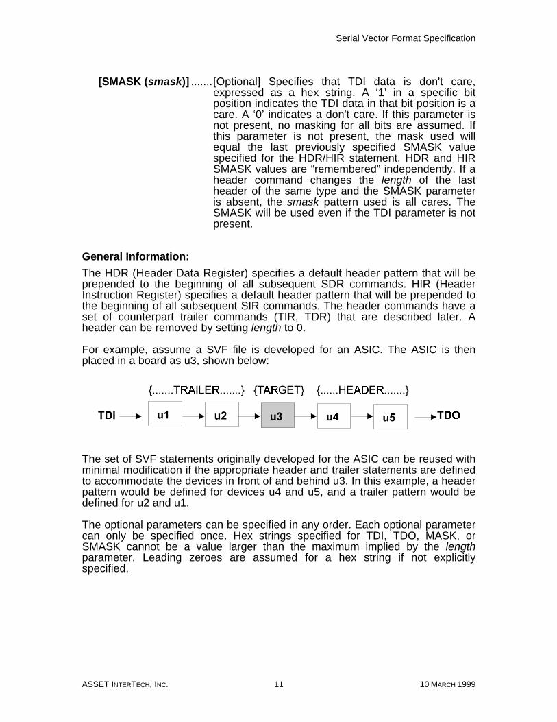
The HDR (Header Data Register) specifies a default header pattern that will beprepended to the beginning of all subsequent SDR commands. HIR (HeaderInstruction Register) specifies a default header pattern that will be prepended tothe beginning of all subsequent SIR commands. The header commands have aset of counterpart trailer commands (TIR, TDR) that are described later. Aheader can be removed by setting length to 0.
For example, assume a SVF file is developed for an ASIC. The ASIC is thenplaced in a board as u3, shown below:
The set of SVF statements originally developed for the ASIC can be reused withminimal modification if the appropriate header and trailer statements are definedto accommodate the devices in front of and behind u3. In this example, a headerpattern would be defined for devices u4 and u5, and a trailer pattern would bedefined for u2 and u1.
The optional parameters can be specified in any order. Each optional parametercan only be specified once. Hex strings specified for TDI, TDO, MASK, orSMASK cannot be a value larger than the maximum implied by the lengthparameter. Leading zeroes are assumed for a hex string if not explicitlyspecified.
Serial Vector Format Specification
10 MARCH 1999 12 ASSET INTERTECH, INC.
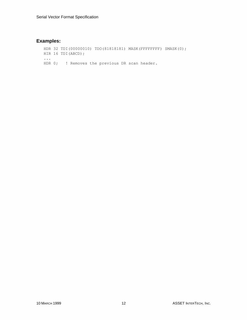
Examples:
HDR 32 TDI(00000010) TDO(81818181) MASK(FFFFFFFF) SMASK(0);HIR 16 TDI(ABCD);...HDR 0; ! Removes the previous DR scan header.

Serial Vector Format Specification
ASSET INTERTECH, INC. 13 10 MARCH 1999
PIO (Parallel Input/Output)
Syntax:
PIO (vector_string);
Purpose:
Specifies a parallel test vector. A PIOMAP statement must have been previouslydefined and the number of vector characters in a PIO statement must equal thenumber of logical names in the previously specified PIOMAP statement.
Parameters:
vector_string ..............A column-oriented set of one or more vectorcharacters. Each character specifies the direction andstate for a specific pin for one test vector. Thefollowing characters are defined:
H.............Drive Logical 1L .............Drive Logical 0Z .............Drive High ImpedanceU.............Detect Logical 1D.............Detect Logical 0X .............Detect Unknown
Note: For bidirectional channels a “Z” implies nodrive/no detect.
Examples:
PIO (HLUDXZHHLL);

Serial Vector Format Specification
10 MARCH 1999 14 ASSET INTERTECH, INC.
PIOMAP (Parallel Input/Output Map)
Syntax:
PIOMAP (direction1 logical_name1…[directionn logical_namen]);
PIOMAP (column1 logical_name1…[columnn logical_namen]);
Purpose:
Defines the I/O direction and logical name for each column in a PIO statement.The PIOMAP statement is required if the SVF file uses the PIO statement. If PIOis used, the PIOMAP statement must be placed in the SVF file prior to any SIR,SDR, STATE, RUNTEST, or PIO statement. Only one PIOMAP statement isallowed per file.
The first form of PIOMAP defines the I/O direction and logical name for eachcolumn, in the order the vector characters appear in the PIO statement. The firstlogical_name corresponds to the first character of the vector_string in PIOstatements; the second logical_name corresponds to the second character of thevector_string; and so forth.
The second form of PIOMAP defines the mapping between a specific column ina PIO statement and the logical name associated with that column. The I/Odirection is not defined, so any vector character may be used in any column.This second form is not recommended for current usage because the I/Odirection cannot be validated.
Parameters:
direction1-n ................Specifies the I/O direction of the logical name. Thedirection may be IN, OUT, or INOUT. A column with adirection of IN is an input to the UUT, and that columnin the PIO statement may use the “drive” characters.An OUT column is an output from the UUT, and mayuse the “detect” characters. An INOUT column is abidirectional signal, and may use any vectorcharacter.
logical_name1-n.........A character string identifying the logical name of thepin associated with the column. The same stringcannot be used more than once in the PIOMAPstatement.
column1-n...................Specifies the column number of the PIO statement.The first character in the PIO statement is column 1,the second character column 2, etc. The columnnumber is decimal. A specific column number cannotbe used more than once. This form of PIOMAP is notrecommended for current usage.
Serial Vector Format Specification
ASSET INTERTECH, INC. 15 10 MARCH 1999
Examples:
!PIOMAP must be placed before PIO statementPIOMAP (IN STROBE IN ALE OUT DISABLE OUT ENABLE OUT CLEAR IN SET);
PIO (HLUDXZ);
!Vector is:! STROBE <- H! ALE <- L! DISABLE <- U! ENABLE <- D! CLEAR <- X! SET <- Z

Serial Vector Format Specification
10 MARCH 1999 16 ASSET INTERTECH, INC.
RUNTEST
Syntax:
RUNTEST [run_state] run_count run_clk [min_time SEC [MAXIMUM max_timeSEC]] [ENDSTATE end_state];
RUNTEST [run_state] min_time SEC [MAXIMUM max_time SEC] [ENDSTATEend_state];
Purpose:
Forces the target IEEE 1149.1 bus to the specified run state for a specifiednumber of clocks (either Test Clocks or System Clocks), a specified length oftime, or both, then moves the target bus to the specified end state. This can beused to control RUNBIST operations in the target.
The first form of the RUNTEST command executes the test in the specified runstate for the specified number of clocks. Optionally, a minimum and maximumtime delay in seconds can be specified. The second form of the RUNTESTcommand executes the test for the specified minimum and maximum number ofseconds. Since RUNTEST is a command that generates vectors, TCK is clockedeven if run_count is not specified.
Either run_count or min_time must be specified. If both run_count and min_timeare specified, both conditions must be met before the RUNTEST commandfinishes execution. If max_time is exceeded, RUNTEST stops before therun_count is reached.
Both min_time and max_time are specified as real numbers. The resolution andrange of the time delay is implementation defined.
The translator shall issue a warning if it cannot guarantee the maximum timewhen the current state before execution of the RUNTEST command is the sameas the run_state, and a max_time is specified. The translator shall also issue aportability warning that the maximum time may be violated in someimplementations under these conditions. An implementation that uses a free-running TCK could be in the run state and clocking longer than max_time, sinceit would have entered the run_state at the end of the previous command, not atthe start of the RUNTEST command.

Serial Vector Format Specification
ASSET INTERTECH, INC. 17 10 MARCH 1999
Parameters:
run_state................................[Optional] The stable IEEE 1149.1 state thatthe IEEE 1149.1 bus will be forced to duringthe RUNTEST command. Valid run states areIRPAUSE, DRPAUSE, RESET, and IDLE. Ifthe test bus is already in the run state, no statetransitions occur. Once a run_state isspecified, subsequent RUNTEST commandswill default to the same run state if one is notspecified. The initial default is IDLE. Forinformation on the default path taken whenmoving from one IEEE 1149.1 state to another,refer to the table on page 22.
run_count ..............................[Optional] The number of clocks that the IEEE1149.1 bus will remain in the run state,expressed as a 32-bit unsigned decimalinteger greater than 0.
run_clk ...................................[Optional] Specifies the clock used, either TCK(Test Clock) or SCK (System Clock). SystemClock refers to a clock on the UUT that isasynchronous with respect to the TCK. TheSystem Clock is implementation dependent.
[min_time SEC] .....................[Optional] The minimum amount of time inseconds that the RUNTEST command mustexecute before finishing.
[MAXIMUM max_time SEC] ..[Optional] The maximum amount of time inseconds that the RUNTEST command mayexecute before it must finish. The maximumtime must be greater than the minimum time. Ifboth run_count and max_time are specified,and not all clocking has completed when themax_time is reached, the command finisheseven though not all the requested clocking hasbeen performed. Whether or not a maximumtime can be guaranteed is implementationdefined.
[ENDSTATE end_state] ........[Optional] The stable IEEE 1149.1 state thatthe IEEE 1149.1 bus will be forced to afterexecuting the specified number of clocks,waiting the specified length of time, or both.Valid end states are IRPAUSE, DRPAUSE,RESET, and IDLE. If the test bus is already inthe end state, no state transitions occur. If theend_state is not specified, the default endstate is used. When an end_state is specified,it becomes the default. When a run_state is

Serial Vector Format Specification
10 MARCH 1999 18 ASSET INTERTECH, INC.
specified, the new run_state becomes thedefault end_state. When a run_state is notspecified, the default end_state remains ineffect. The initial default for end_state is IDLE.
Examples:
! Run in Run-Test/Idle for 1000 TCKs, then go to Pause-DR.RUNTEST 1000 TCK ENDSTATE DRPAUSE;! Go back to Run-Test/Idle for 20 SCKs, then go to Pause-DR.RUNTEST 20 SCK;! Run in Run-Test/Idle for 1000000 TCKs or at least one second,! then go to Pause-DR.RUNTEST 1000000 TCK 1 SEC;! Run in Run-Test/Idle for at least one millisecond and at most! 50 milliseconds, then remain in Run-Test/Idle.RUNTEST 10.0E-3 SEC MAXIMUM 50.0E-3 SEC ENDSTATE IDLE;! Run in Pause-DR for at least 50 ms, then go to Run-Test/Idle.RUNTEST DRPAUSE 50E-3 SEC ENDSTATE IDLE;! Run in Pause-DR for at least one second, then go to Run-Test/Idle.RUNTEST 1 SEC;! Run in Run-Test/Idle for at least 10 ms, then remain in! Run-Test/Idle.RUNTEST IDLE 1E-2 SEC;
Serial Vector Format Specification
ASSET INTERTECH, INC. 19 10 MARCH 1999
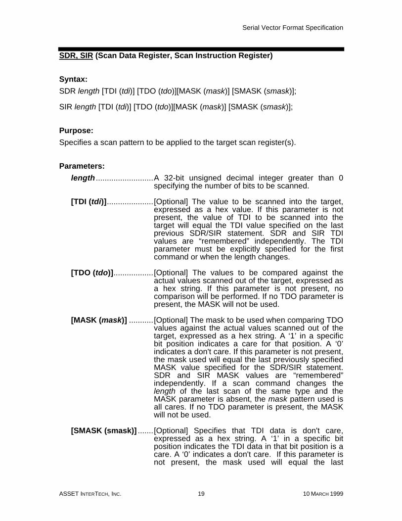
SDR, SIR (Scan Data Register, Scan Instruction Register)
Syntax:
SDR length [TDI (tdi)] [TDO (tdo)][MASK (mask)] [SMASK (smask)];
SIR length [TDI (tdi)] [TDO (tdo)][MASK (mask)] [SMASK (smask)];
Purpose:
Specifies a scan pattern to be applied to the target scan register(s).
Parameters:
length ..........................A 32-bit unsigned decimal integer greater than 0specifying the number of bits to be scanned.
[TDI (tdi)].....................[Optional] The value to be scanned into the target,expressed as a hex value. If this parameter is notpresent, the value of TDI to be scanned into thetarget will equal the TDI value specified on the lastprevious SDR/SIR statement. SDR and SIR TDIvalues are “remembered” independently. The TDIparameter must be explicitly specified for the firstcommand or when the length changes.
[TDO (tdo)]..................[Optional] The values to be compared against theactual values scanned out of the target, expressed asa hex string. If this parameter is not present, nocomparison will be performed. If no TDO parameter ispresent, the MASK will not be used.
[MASK (mask)] ...........[Optional] The mask to be used when comparing TDOvalues against the actual values scanned out of thetarget, expressed as a hex string. A ‘1’ in a specificbit position indicates a care for that position. A ‘0’indicates a don't care. If this parameter is not present,the mask used will equal the last previously specifiedMASK value specified for the SDR/SIR statement.SDR and SIR MASK values are “remembered”independently. If a scan command changes thelength of the last scan of the same type and theMASK parameter is absent, the mask pattern used isall cares. If no TDO parameter is present, the MASKwill not be used.
[SMASK (smask)] .......[Optional] Specifies that TDI data is don't care,expressed as a hex string. A ‘1’ in a specific bitposition indicates the TDI data in that bit position is acare. A ‘0’ indicates a don't care. If this parameter isnot present, the mask used will equal the last

Serial Vector Format Specification
10 MARCH 1999 20 ASSET INTERTECH, INC.
previously specified SMASK value specified for theSDR/SIR statement. SDR and SIR SMASK values are“remembered” independently. If a scan commandchanges the length of the last scan of the same typeand the SMASK parameter is absent, the smaskpattern used is all cares. The SMASK will be usedeven if the TDI parameter is not present.
General Information:
The SDR (Scan Data Register) specifies a scan pattern to be scanned to thetarget Data Register. The SIR (Scan Instruction Register) specifies a scanpattern to be scanned to the target Instruction Register.
Prior to scanning the values specified in the SDR or SIR command, the lastdefined header command (HDR or HIR, respectively) will be prepended to thebeginning of the SDR or SIR data pattern and the last defined trailer command(TDR or TIR, respectively) will be appended to the end of the SDR or SIR datapattern.
The optional parameters can be specified in any order. Each optional parametercan only be specified once. Hex strings specified for TDI, TDO, MASK, orSMASK cannot be a value larger than the maximum implied by the lengthparameter. Leading zeroes are assumed for a hex string if not explicitlyspecified.
Examples:
SDR 24 TDI(000010) TDO(818181) MASK(FFFFFF) SMASK(0);SIR 16 TDI(ABCD);

Serial Vector Format Specification
ASSET INTERTECH, INC. 21 10 MARCH 1999
STATE
Syntax:
STATE [pathstate1 [pathstate2 ...[pathstaten]]] stable_state ;
Purpose:
Forces the target IEEE 1149.1 bus to a stable IEEE 1149.1 state.
Parameters:
pathstate1-n ..................An optional list of one or more IEEE 1149.1 statesdescribing the explicit path through the Test AccessPort (TAP) state diagram that is taken in order toreach the final stable state. Valid states are RESET,IDLE, DRSELECT, DRCAPTURE, DRSHIFT,DRPAUSE, DREXIT1, DREXIT2, DRUPDATE,IRSELECT, IRCAPTURE, IRSHIFT, IRPAUSE,IREXIT1, IREXIT2, and IRUPDATE. The states mustbe listed in an order that complies with the TAP statediagram. If the pathstate parameters are not listed, adefault path is assumed based on the current stateand the final stable state, as listed in the followingtable.
stable_state ................The stable IEEE 1149.1 state that the IEEE 1149.1bus will be forced to. Valid stable states areIRPAUSE, DRPAUSE, RESET, and IDLE.
Examples:
!Force bus to DRPAUSE from current state it is inSTATE DRPAUSE;
!Dictate explicit path bus will take moving from! DRPAUSE to IRPAUSESTATE DREXIT2 DRUPDATE DRSELECT IRSELECT IRCAPTURE IREXIT1 IRPAUSE;
General Information:
The STATE command is used to move the IEEE 1149.1 bus from one stablestate to another for UUT test initialization, completion or TAP controller testing.TDI and TDO values are undefined when using the STATE command.
If no pathstate parameters are specified, the STATE command always followsthe same path through the IEEE 1149.1 state diagram when moving from onestable state to another. The following table indicates the path taken for eachstable state. For every state path, it is assumed that at least one Test Clock willbe executed.

Serial Vector Format Specification
10 MARCH 1999 22 ASSET INTERTECH, INC.
CurrentState
NewState State Path
RESET RESET RESET
RESET IDLE RESET-IDLE
RESET DRPAUSE RESET-IDLE-DRSELECT-DRCAPTURE-DREXIT1-DRPAUSE
RESET IRPAUSE RESET-IDLE-DRSELECT-IRSELECT-IRCAPTURE-IREXIT1-IRPAUSE
IDLE RESET IDLE-DRSELECT-IRSELECT-RESET
IDLE IDLE IDLE
IDLE DRPAUSE IDLE-DRSELECT-DRCAPTURE-DREXIT1-DRPAUSE
IDLE IRPAUSE IDLE-DRSELECT-IRSELECT-IRCAPTURE-IREXIT1-IRPAUSE
DRPAUSE RESET DRPAUSE-DREXIT2-DRUPDATE-DRSELECT-IRSELECT-RESET
DRPAUSE IDLE DRPAUSE-DREXIT2-DRUPDATE-IDLE
DRPAUSE DRPAUSE DRPAUSE-DREXIT2-DRUPDATE-DRSELECT-DRCAPTURE-DREXIT1-DRPAUSE
DRPAUSE IRPAUSE DRPAUSE-DREXIT2-DRUPDATE-DRSELECT-IRSELECT-IRCAPTURE-IREXIT1-IRPAUSE
IRPAUSE RESET IRPAUSE-IREXIT2-IRUPDATE-DRSELECT-IRSELECT-RESET
IRPAUSE IDLE IRPAUSE-IREXIT2-IRUPDATE-IDLE
IRPAUSE DRPAUSE IRPAUSE-IREXIT2-IRUPDATE-DRSELECT-DRCAPTURE-DREXIT1-DRPAUSE
IRPAUSE IRPAUSE IRPAUSE-IREXIT2-IRUPDATE-DRSELECT-IRSELECT-IRCAPTURE-IREXIT1-IRPAUSE

Serial Vector Format Specification
ASSET INTERTECH, INC. 23 10 MARCH 1999
TDR, TIR (Trailer Data Register, Trailer Instruction Register)
Syntax:
TDR length [TDI (tdi)] [TDO (tdo)][MASK (mask)] [SMASK (smask)];
TIR length [TDI (tdi)] [TDO (tdo)][MASK (mask)] [SMASK (smask)];
Purpose:
Specifies a default trailer pattern that is shifted in after all subsequent scanoperations. This command is intended to allow a set of scan statements for aspecific IEEE 1149.1 component to be easily adapted to an environment wherethe component is placed in a scan path containing other IEEE 1149.1 devices.The trailer pattern specifies how to pad the scan statements with a set of trailingbits that accommodate the devices located on the scan path after the componentof interest.
Parameters:
length ..........................A 32-bit unsigned decimal integer specifying thenumber of bits to be scanned. Setting the length to 0removes the trailer.
[TDI (tdi)].....................[Optional] The value to be scanned into the target,expressed as a hex value. If this parameter is notpresent, the value of TDI to be scanned into thetarget will equal the TDI value specified on the lastprevious TDR/TIR statement. TDR and TIR TDIvalues are “remembered” independently. The TDIparameter must be explicitly specified for the firstcommand or when the length changes.
[TDO (tdo)]..................[Optional] The values to be compared against theactual values scanned out of the target, expressed asa hex string. If this parameter is not present, nocomparison will be performed.
[MASK (mask)] ...........[Optional] The mask to be used when comparing TDOvalues against the actual values scanned out of thetarget, expressed as a hex string. A ‘1’ in a specificbit position indicates a care for that position. A ‘0’indicates a don't care. If this parameter is not present,the mask used will equal the last previously specifiedMASK value specified for the TDR/TIR statement.TDR and TIR MASK values are “remembered”independently. If a trailer command changes thelength of the last trailer of the same type and theMASK parameter is absent, the mask pattern used is

Serial Vector Format Specification
10 MARCH 1999 24 ASSET INTERTECH, INC.
all cares. If no TDO parameter is present, the MASKwill not be used.
[SMASK (smask)] .......[Optional] Specifies which TDI data is don't care,expressed as a hex string. A ‘1’ in a specific bitposition indicates the TDI data in that bit position is acare. A ‘0’ indicates a don't care. If this parameter isnot present, the mask used will equal the lastpreviously specified SMASK value specified for theTDR/TIR statement. TDR and TIR SMASK values are“remembered” independently. If a trailer commandchanges the length of the last trailer of the same typeand the SMASK parameter is absent, the smaskpattern used is all cares. The SMASK will be usedeven if the TDI parameter is not present.
General Information:
The TDR (Trailer Data Register) specifies a trailer pattern that will be appendedto the end of all subsequent SDR commands. TIR (Trailer Instruction Register)specifies a default trailer pattern that will be appended to the end of allsubsequent SIR commands A trailer can be removed by setting length to 0.
For example, assume a SVF file is developed for an ASIC. The ASIC is thenplaced in a board as u3, shown below:
The set of SVF statements originally developed for the ASIC can be reused withminimal modification if the appropriate header and trailer statements are definedto accommodate the devices in front of and behind u3. In this example, a headerpattern would be defined for devices u4 and u5, and a trailer pattern would bedefined for u1 and u2.
The optional parameters can be specified in any order. Each optional parametercan only be specified once. Hex strings specified for TDI, TDO, MASK, orSMASK cannot be a value larger than the maximum implied by the lengthparameter. Leading zeroes are assumed for a hex string if not explicitlyspecified.
Serial Vector Format Specification
ASSET INTERTECH, INC. 25 10 MARCH 1999
Examples:
TDR 32 TDI(00000010) TDO(81818181) MASK(FFFFFFFF) SMASK(0);TIR 16 TDI(ABCD);...TDR 0; ! Removes the previous DR scan trailer.
Serial Vector Format Specification
10 MARCH 1999 26 ASSET INTERTECH, INC.
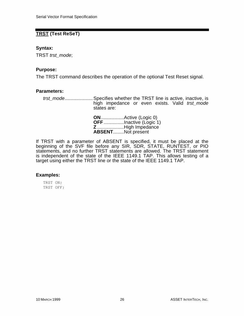
TRST (Test ReSeT)
Syntax:
TRST trst_mode;
Purpose:
The TRST command describes the operation of the optional Test Reset signal.
Parameters:
trst_mode.....................Specifies whether the TRST line is active, inactive, ishigh impedance or even exists. Valid trst_modestates are:
ON .................Active (Logic 0)OFF ...............Inactive (Logic 1)Z ....................High ImpedanceABSENT........Not present
If TRST with a parameter of ABSENT is specified, it must be placed at thebeginning of the SVF file before any SIR, SDR, STATE, RUNTEST, or PIOstatements, and no further TRST statements are allowed. The TRST statementis independent of the state of the IEEE 1149.1 TAP. This allows testing of atarget using either the TRST line or the state of the IEEE 1149.1 TAP.
Examples:
TRST ON;TRST OFF;