sequence diagram generation with model transformation ... · the design of object-oriented systems....
TRANSCRIPT
Abstract— Creating Sequence diagrams with UML tools can
be incomplete, inconsistent, and incorrect. It also requires
expertise, effort, and time. With model transformation
technology, this paper presents an approach to automate the
generation of UML Sequence diagrams from Use Case
Description and Class diagrams. ATL is used as the model
transformation language for converting the source metamodels
of Use Case description and Class diagrams to the target
metamodel of Sequence diagram. The resulting file in XMI
format is then transformed by XSLT to another XMI file that
suits for rendering the image of Sequence diagram as the final
output. The proposed method would result in the improvement
of software process. Rather than constructing the models from
scratch during the different development life cycle stages,
model transformations enable the reuse of information that
was once modeled, as well as enhance the consistency among
the models representing different views of the system.
Index Terms—model-driven, model transformation,
sequence diagram, process improvement
I. INTRODUCTION
ODAY, UML is accepted by the Object Management
Group (OMG) as the standard for modeling object
oriented programs. Several diagrams are defined to support
the design of object-oriented systems. One of the UML
diagrams includes the Sequence diagram which is used
primarily to show the interactions between objects in the
sequential order that those interactions occur. The diagrams
allow the designer to specify the sequence of messages sent
between objects in collaboration. As opposed to
Collaboration diagrams, Sequence diagrams emphasize the
sequence of the messages rather than the relationships
between the objects.
UML models had been improved by the OMG to be
capable of delivering Model Driven Architecture (MDA),
i.e. the UML had to function as a more model driven
notation. Model driven describes an approach to software
development whereby models are used as the primary
source for documenting, analyzing, designing, constructing,
deploying, and maintaining a system. The promotion of
MDA as an architectural framework for software
development is one of the major initiatives accomplished
P. Sawprakhon is a graduate student pursuing Master degree of Science
in Software Engineering, Department of Computer Engineering,
Chulalongkorn University, Bangkok 10330, Thailand (e-mail:
Y. Limpiyakorn is an Associate Professor in Department of Computer
Engineering, Chulalongkorn University, Bangkok 10330, Thailand (e-mail:
by the OMG to help reduce complexity, lower costs, and
hasten the introduction of new software applications.
Metamodeling and model transformations are the key
concepts in Model Driven Development (MDD) approaches
as they provide a mechanism for automated development of
well-structured and maintainable systems [1]. Metamodeling
provides a means of describing models with complete and
precise specification. Different models represent different
views of the system, and they are constructed conforming to
their metamodels. A model transformation is the process of
converting a source model into a target model via a model
transformation language. The current well-known
transformation languages include QVT (Query/ View/
Transformation) and ATL (ATLAS Transformation
Language). Model transformations play a role to create new
models based on the existing information throughout the
MDD process. Rather than constructing the models from
scratch during the different development life cycle stages,
model transformations enable the reuse of information that
was once modeled, as well as enhance the consistency
among the models representing different views of the
system.
This article presents a method to automate the generation
of UML Sequence diagrams from Use Case Description
(UCD) and Class diagrams. With a set of rules defined in
the chosen model transformation language ATL, the source
metamodels of Use Case Description and Class diagrams are
converted to the target metamodel of Sequence diagram.
The resulting file in XMI format is then transformed by
XSLT (eXtensible Stylesheet Language Transformations) to
another XMI file that suits for rendering the image of
Sequence diagram via the visualization program.
II. MODEL DRIVEN DEVELOPMENT
MDD is based on several concepts and technologies like
model, metamodel, meta-metamodel, Model Driven
Architecture, and model transformation. A model is an
abstract representation of a system defined in a modeling
language. Models are the primary artifacts of the MDD
process and they represent the system on different levels of
abstraction. A model contains enough details for (semi)
automatic generation of executable code.
A. Model Transformation
Meta-model is the construction of a collection of
"concepts" within a certain model [2]. A model is an
abstraction of reality in the real world, while a metamodel is
another abstraction highlighting properties of the model
itself. A model conforms to its metamodel similar to the way
Sequence Diagram Generation with Model
Transformation Technology
Photchana Sawprakhon, Yachai Limpiyakorn
T
Proceedings of the International MultiConference of Engineers and Computer Scientists 2014 Vol I, IMECS 2014, March 12 - 14, 2014, Hong Kong
ISBN: 978-988-19252-5-1 ISSN: 2078-0958 (Print); ISSN: 2078-0966 (Online)
IMECS 2014

that a computer program conforms to the grammar of the
programming language in which it is written.
The Meta-Object Facility (MOF) [3] can be regarded as
an OMG standard to write metamodels. MOF originated in
the Unified Modeling Language as a metamodeling
architecture to define the UML. MOF is designed as a four-
layered architecture as shown in Fig. 1. It provides a meta-
metamodel at the top layer, called the M3-layer. The MOF
meta-metamodel is referred as the MOF Model. This M3-
model is the language used by MOF to build metamodels,
called M2-models. An example of a Level 2 MOF model is
the UML metamodel, which is the model describing the
UML itself. MOF metamodels are usually modeled as UML
Class diagrams. These M2-models describe elements of the
M1-layer, and thus M1-models. Examples of M1-models
include those models created in UML, such as Class and
Sequence diagrams. The last layer is the M0-layer or data
layer. It is used to describe real world objects, such as code
and documentation. The XML Metadata Interchange (XMI)
[4] is a standard format for exchanging information about
MOF compliant models (M3, M2, M1 Levels) using the
eXtensible Markup Language (XML). It includes
information about elements in a model and their
relationships.
Fig. 1. Metamodeling layers in MOF.
The MOF specification is the foundation of the OMG
standard environment where models can be created,
integrated, and transformed into different formats. The
OMG’s Model Driven Architecture relies on the MOF to
integrate the modeling steps and provide the model
transformations.
Model transformations aim to provide a means to produce
target models from a number of source models in the scope
of Model Driven Engineering (MDE). MDE is a software
development methodology that is mainly concerned with the
evolution of models as a means of developing software by
focusing on models. Some of the well-known MDE
initiatives include the OMG’s initiative of Model Driven
Architecture, and the Eclipse ecosystem of programming
and modeling tools (Eclipse Modeling Framework EMF)
[5].
Model transformations in MDE follow a common pattern
as depicted in Fig. 2. A model conforms to a metamodel,
while a metamodel conforms to a meta-metamodel. The
transformation model defines how to generate models that
conform to a particular metamodel from models that
conform to another metamodel or the same metamodel.
From Fig. 2, the transformation model Mt transforms Ma to
Mb. Mt, Ma, and Mb are the models conforming to MMt,
MMa, and MMb, respectively. The three metamodels
conform to a common meta-metamodel MMM.
Fig. 2. Pattern of model transformations [6].
B. Atlas Transformation Language (ATL)
ATL [7] is a model transformation language and toolkit.
It is one of the most popular and widely used model
transformation languages. ATL is a hybrid model
transformation language containing a mixture of declarative
and imperative constructs based on Object Constraint
Language (OCL) for writing expressions. ATL transformations are unidirectional, i.e. operating on read-
only source models and producing write-only target models.
During the execution of a transformation, source models can
be navigated but changes are not allowed. Target models
cannot be navigated.
ATL provides a means to produce a number of target
models from a set of source models. An ATL transformation
program is composed of rules that define how source model
elements are matched and navigated to create and initialize
the elements of the target models. Developers can define the
way source model elements must be matched and navigated
in order to initialize the target model elements. ATL is a hybrid of declarative and imperative. The preferred style of
transformation writing is declarative, providing that simple
mappings can be expressed simply. However, imperative
constructs are provided so that complex mappings can still
be specified.
Fig. 3 illustrates when ATL is applied in the context of
the transformation pattern. A source model Ma is
transformed into a target model Mb according to a
transformation definition mma2mmb.atl written in ATL.
The transformation definition is a model conforming to the
ATL metamodel (Fig. 4). All metamodels conform to MOF.
ATL is developed on Eclipse platform. Eclipse platform
defines EMF framework which is a modeling framework
and code generation facility for building tools and other
applications based on a structured data model. The core EMF framework includes a metamodel (ECORE) for
describing models and runtime support for the models
including change notification, persistence support with
default XMI serialization, and a very efficient reflective API
for manipulating EMF objects generically.
ECORE is the core meta-model at the heart of EMF. It
allows expressing other models by leveraging its constructs.
ECORE is also its own meta-model because ECORE is
defined in terms of itself.
Proceedings of the International MultiConference of Engineers and Computer Scientists 2014 Vol I, IMECS 2014, March 12 - 14, 2014, Hong Kong
ISBN: 978-988-19252-5-1 ISSN: 2078-0958 (Print); ISSN: 2078-0966 (Online)
IMECS 2014

Fig. 3. Transformation pattern with ATL [8].
Fig. 4. Tailored ATL metamodel.
III. IMPLEMENTATION
The process of model transformation consists of four main
steps as illustrated in Fig. 5. Details are briefly explained in
the following subsections.
1. Create Source Models
In this research, the input of Use Case and Class diagrams
are created using Visual Paradigm v. 8, that supports UML2
The diagrams created with Visual Paradigm can be exported
in XMI-format files (.uml). Moreover, Visual Paradigm
provides the feature that supports the insertion of
descriptions into Use Case diagrams. The Use Case diagram
with inserted descriptions will then be exported in XMI
format (usecaseWithDesc.uml), and transformed to the
target model (usecaseDesc.uml) with ATL transformation as
shown in Fig. 6. A set of mapping rules is defined, together
with the source metamodel of Use Case (Fig. 7) and the
target metamodel of Use Case Description (Fig. 8) are
created to support the ATL transformation process. Since
the metamodel of Use Case Description is not defined as a
standard of the OMG, the method how to build the UCD
metamodel presented in [9] is adopted in this work.
2. ATL Transformation
The XMI files of Use Case Description and Class diagram
are input to the ATL transformation for generating the
output XMI file of Sequence diagram as illustrated in Fig. 9.
The source metamodels of Use Case Description (Fig. 8)
and Class diagram (Fig. 10), accompanied with the target
metamodel of Sequence diagram (Fig. 11) are used during
the ATL transformation process. This research has applied
the approach presented in [10], [11] for creating a Sequence
diagram from the messages in UCD based on the knowledge
of natural language and the principles of artificial
intelligence.
In addition, a set of mapping rules is defined as
summarized in Table 1. Each rule covers the construction of
the component of Sequence diagram from the source
models. That is,
Rule 1: Create Message
Rule 2: Create Lifeline
Rule 3: Create Sender receiving message
Rule 4: Create Receiver receiving message
Rule 5: Create Combined Fragment having value of alternatives
Rule 6: Create Combined Fragment having value of options
Rule 7: Create Combined Fragment having value of loops
IF (UCD)Sentence.verb match any (CL)Operation.name THEN
(SQ)Message.name = (CL)Operation.name ELSE (SQ)Message.name = (UCD)Sentense.verb
END IF
IF (UCD)Sentence.verb match any (CL)Operation.name THEN (SQ)Lifeline.name = (CL)Class.name ELSE (SQ)Lifeline.name = (UCD)Sentense.object END IF
IF (UCD)Sentence.noun match any (CL)Class.name THEN
start = (CL)Class.name ELSE /*create new Lifeline using Sentense.noun*/ start = (UCD)Sentense.noun END IF
IF (UCD)Sentence.object match any (CL)Class.name THEN finish = (CL)Class.name ELSE /*create new Lifeline using Sentense.object*/ start = (UCD)Sentense.object END IF
IF (UCD)Item.name match 'Alternative flows and exceptions' and (UCD)flowOfEvent.sequenceNumber exists in Item.value THEN
(SQ)Combineedfragment.interactionOperator = 'alt' END IF
IF (UCD)Item.name match 'Alternative flows and exceptions' and (UCD)flowOfEvent.sequenceNumber exists in Item.value THEN
(SQ)Combineedfragment.interactionOperator ='opt' END IF
IF (UCD)Alternater.name match 'loop' THEN
(SQ)Combineedfragment.interactionOperator ='loop' END IF
Proceedings of the International MultiConference of Engineers and Computer Scientists 2014 Vol I, IMECS 2014, March 12 - 14, 2014, Hong Kong
ISBN: 978-988-19252-5-1 ISSN: 2078-0958 (Print); ISSN: 2078-0966 (Online)
IMECS 2014
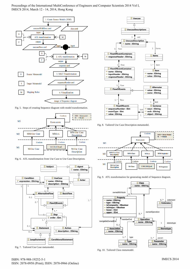
Fig. 5. Steps of creating Sequence diagram with model transformation.
Fig. 6. ATL transformation from Use Case to Use Case Description.
Fig. 7. Tailored Use Case metamodel.
Fig. 8. Tailored Use Case Description metamodel.
Fig. 9. ATL transformation for generating model of Sequence diagram.
Fig. 10. Tailored Class metamodel.
Proceedings of the International MultiConference of Engineers and Computer Scientists 2014 Vol I, IMECS 2014, March 12 - 14, 2014, Hong Kong
ISBN: 978-988-19252-5-1 ISSN: 2078-0958 (Print); ISSN: 2078-0966 (Online)
IMECS 2014

Fig. 11. Tailored Sequence metamodel.
TABLE I
EXAMPLE MAPPING RULE TRANSFORMATION
Input Output
Mapping
Rule Class Meta-Model
(CL)
Use Case Description Meta-model
(UCD)
Sequence Meta-Model
(SEQ)
EClass1 EAttribute
2 EClass
1 EAttribute
2 Element Symbol Example EClass
1 EAttribute
2
- - <Item> <name> <Actor>
<Lifeline> <name>
-
<Operation> <name> <Sentence> <verb> <Message>
<Message> <name> Rule1
<Class> <name> <Sentence> <object> <Lifeline>
<Lifeline> <name> Rule2
<Class> <name> <Sentence> <noun> (message)
<start>
- - Rule3
<Class> <name> <Sentence> <object> (message)
<finish>
- - Rule4
- -
<Item> <name> Fragment
Alternative
<Combined
Fragment>
<interaction
Operator >
(alt)
Rule5
<flowOfEvent <sequenceNumber>
- -
<Item> <name> Fragment
Option
<Combined
Fragment>
<Interaction
Operator >
(opt)
Rule6
<flowOfEvent> <sequenceNumber>
<Alternater> <name> Fragment
Loop
<Combined
Fragment>
<interaction
Operator >
(loop)
Rule7
<Item>
<name>
(pre-condition,
post-condition)
Interaction
Use
<Interaction>
<name>
-
1EClass is represents a class, with zero or more attributes and zero or more references.
2EAttribue is represents an attribute which has a name and a type.
eceiver is …
Proceedings of the International MultiConference of Engineers and Computer Scientists 2014 Vol I, IMECS 2014, March 12 - 14, 2014, Hong Kong
ISBN: 978-988-19252-5-1 ISSN: 2078-0958 (Print); ISSN: 2078-0966 (Online)
IMECS 2014

3. XSLT Transformation
The XMI format of Sequence diagram as output from the
previous step still cannot be image rendered. Another
transformation process (Fig. 12) is required to construct the
XMI format that suits for image rendering.
Fig. 12. XSLT transformation process.
4. Visualization
The output XMI-format file (sequenceRender.uml) of
Sequence diagram from the previous step is input to the
visualization tool, Visual Paradigm, for generating the
image of Sequence diagram that conforms to UML standard
of OMG.
IV. CONCLUSION
UML Sequence diagrams are widely used to describe interactions among classes in terms of an exchange of
messages over time. They clearly display the sequence of
events, show when objects are created and destroyed, are
excellent at depicting concurrent operations, and help
hunting down race conditions. However, the task of creating
Sequence diagrams is error-prone and consumes effort and
time. With model transformation technology, this article
presents a method and develops a prototype to facilitate the
generation of UML Sequence diagrams from UCD and
Class diagrams. The tool has been developed based on
Eclipse Modeling Tools (Kepler-SR1), and ATL is used as the model transformation language. The ATL scripts
containing a set of mapping rules are created and executed
using Eclipse Modeling IDE. Two ATL plugins are
implemented and installed as the extension of Eclipse
Modeling IDE. When applying model transformation, if the
target model conforms to the target metamodel
specification, then the model transformation is syntactically
correct. Since the target metamodel specification of the
Sequence diagram in this work is defined based on the
OMG standard, the generated Sequence diagrams are thus
syntactically correct.
REFERENCES
[1] D. Cetinkaya and A. Verbraeck, "Metamodeling and model
transformations in modeling and simulation," Simulation Conference
(WSC), Proceedings of the 2011 Winter, pp. 3043–3053, Dec. 2011.
[2] Object Management Group, Unified Modeling LanguageTM
(OMG
UML), Superstructure Version 2.4.1, OMG, Inc., Aug. 2011.
[3] Object Management Group, Meta Object Facility (MOF) 2.0
Query/View/Transformation Specification version 1.1, OMG, Inc.,
Jan. 2011.
[4] Object Management group, “MOF/XMI Mapping version 2.4.1,”
OMG, Inc., Jun. 2013.
[5] D. Steinberg, F. Budinsky, M. Paternostro, and E. Merks, EMF
Eclipse Modeling Framework., Addison-Wesley Professional, Boston,
2008.
[6] Eclipse Foundation, ATL Concepts, Nov. 2013, [Online].
Available: http://wiki.eclipse.org/ATL/Concept
[7] Eclipse Foundation, ATL Transformation Language, Dec. 2013,
[Online]. Available: http://www.eclipse.org/atl/atlTransformations
[8] F. Jouault, F. Allilaire, J. Bezivin, and I. Kurtev, "ATL: A model
transformation tool," Science of Computer Programming, vol. 72,
Issues 1–2, Jun. 2008, pp. 31–39.
[9] S. S. Some, “A Meta-Model for Textual Use Case Description”,
Journal of Object Technology, vol. 8, no. 7, pp. 87–106, submitted for
publication.
[10] J. M. Almendros-Jimenez and L. Iribarne, “Describing Use-Case
Relationships with Sequence Diagrams,” The Computer Journal
Advance Access, submitted for publication.
[11] M. C. Segundo, M. C. Herrera, and I. K. Herrera, "UML Sequence
Diagram Generator System from Use Case Description Using Natural
Language," Electronics, Robotics and Automotive Mechanics
Conference, pp. 360–363, Sep. 2007.
Proceedings of the International MultiConference of Engineers and Computer Scientists 2014 Vol I, IMECS 2014, March 12 - 14, 2014, Hong Kong
ISBN: 978-988-19252-5-1 ISSN: 2078-0958 (Print); ISSN: 2078-0966 (Online)
IMECS 2014