september 2014 cp400 series commercial/industrial pressure ... · bulletin 71.1:cp400 september...
TRANSCRIPT
Bulletin 71.1:CP400September 2014
D10
3136
X01
2
www.fisherregulators.com
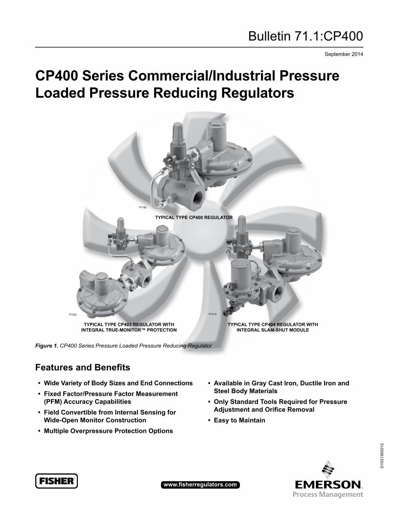
CP400 Series Commercial/Industrial Pressure Loaded Pressure Reducing Regulators
Figure 1. CP400 Series Pressure Loaded Pressure Reducing Regulator
Features and Benefits• Wide Variety of Body Sizes and End Connections• Fixed Factor/Pressure Factor Measurement
(PFM) Accuracy Capabilities• Field Convertible from Internal Sensing for
Wide-Open Monitor Construction• Multiple Overpressure Protection Options
P1182
• Available in Gray Cast Iron, Ductile Iron and Steel Body Materials
• Only Standard Tools Required for Pressure Adjustment and Orifice Removal
• Easy to Maintain
TyPICAL TyPE CP403 REGuLATOR WITH INTEGRAL TRuE-MONITOR™ PROTECTION
TyPICAL TyPE CP404 REGuLATOR WITH INTEGRAL SLAM-SHuT MODuLE
TyPICAL TyPE CP400 REGuLATOR
P1522 P1410
Bulletin 71.1:CP400
2
IntroductionThe CP400 Series pressure loaded regulators have been engineered to fit a multitude of pressure-reducing applications including light industrial and commercial installations, which include accurate control for use in pressure-factor measurement (fixed factor billing) applications. This flexibility is provided by the numerous body end connection sizes, body materials, outlet pressure settings, orifice sizes, as well as the option for internal or external pressure registration. In addition to application flexibility, the CP400 Series offers multiple overpressure protection options to meet your demands on application requirements.
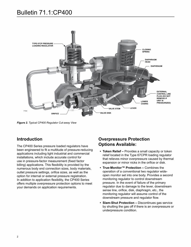
Figure 2. Typical CP400 Regulator Cut-away View
TyPE 67CP PRESSuRE LOADING REGuLATOR
ORIFICE VALVE DISK
LOWER CASING
DIAPHRAGM
DIAPHRAGM HEAD
CLOSING SPRING
VALVE STEM
EXTERNAL CONTROL LINE PLuG (DO NOT REMOVE IF uNIT IS PRESSuRIZED)
LEVERP1562
Overpressure Protection Options Available: • Token Relief – Provides a small capacity or token
relief located in the Type 67CPR loading regulator that relieves minor overpressure caused by thermal expansion or minor nicks in the orifice or disk.
• True-Monitor™ Protection – Combines the operation of a conventional two regulator wide-open monitor set into one body. Provides a second monitoring regulator to control downstream pressure. In the event of failure of the primary regulator due to damage to the lever, downstream sense line, orifice, disk, diaphragm, etc., the monitoring regulator will assume control of the downstream pressure and regulator flow.
• Slam-Shut Protection – Discontinues gas service by shutting the gas off if there is an overpressure or underpressure condition.
Bulletin 71.1:CP400
3
SpecificationsAvailable Configurations Type CP400IN: Type CP400 with
INTERNAL pressure registration and NON-RELIEVING construction
Type CP400IT: Type CP400 with INTERNAL pressure registration and TOKEN relief
Type CP400EN: Type CP400 with EXTERNAL pressure registration and NON-RELIEVING construction
Type CP400ET: Type CP400 with EXTERNAL pressure registration and with TOKEN relief
Type CP403IN: Type CP400IN with integral TRUE-MONITOR™ Protection
Type CP403IT: Type CP400IT with integral TRUE-MONITOR Protection
Type CP403EN: Type CP400EN with integral TRUE-MONITOR Protection
Type CP403ET: Type CP400ET with integral TRUE-MONITOR Protection
Type CP404IN: Type CP400IN with integral Type VSX4 Slam-shut module
Type CP404IT: Type CP400IT with integral Type VSX4 Slam-shut module
Type CP404EN: Type CP400EN with integral TypeVSX4 Slam-shut module
Type CP404ET: Type CP400ET with integral Type VSX4 Slam-shut module
See Table 1Body Sizes, Material, End Connections and Pressure Rating(1)
See Table 2Inlet Pressure Ratings(1)
See Table 3Maximum Outlet Pressures(1)
See Table 4Outlet Pressure Ranges(1)
See Table 5Token Relief Start-to-Discharge See Table 11Flow Capacities Type CP400 See Tables 12 through 17, 20 through 25 Types CP403 and CP404 See Tables 18, 19, 26 and 27 Type CP400 for Pressure Factor Measurement
(PFM) Applications See Tables 29 through 34Temperature Capabilities(1)(2)
-20 to 150°F / -29 to 66°C
Spring Case Vent and Body Orientation See Figure 7 Construction Materials CP400 Series Main Valve and Actuator Body: Gray Cast Iron, Ductile Iron and Steel Body O-ring: Nitrile (NBR) Closing Cap: Aluminum Adjusting Screw: Aluminum Diaphragm Case, Spring Case, Diaphragm Plate
and Valve Stem: Aluminum Diaphragm Plate: Steel Orifice: Aluminum Pusher Post: Aluminum Diaphragm and Disk: Nitrile (NBR) Relief Valve Seat: Aluminum Control Spring: Stainless steel Relief Valve Stem: Aluminum Diaphragm Retainer: Zinc-plated steel Lever Pin: Stainless steel Spring Seat: Aluminum Lever: Steel 67CP Series Pressure Loading Regulator Spring: Music wire or Stainless steel Body: Aluminum O-ring and Soft Seat: Nitrile (NBR) Valve Stem: Aluminum Valve Plug: Nitrile (NBR) Diaphragm: Nitrile (NBR) True-Monitor Actuator Diaphragm Case, Spring Case, Upper Retainer,
Monitor Housing and Valve Stem: Aluminum Diaphragm Plate, Middle Diaphragm Retainer and
Low Disk Retainer: Steel Diaphragm and Disk: Nitrile (NBR) Control Spring: Stainless steel Disk Housing: Brass Vent Screen: Stainless steel Vent Screen Retainer: Stainless steel Closing Cap: Aluminum Adjusting Screw: Aluminum Type VSX4 Slam-Shut Device Diaphragm Case, Spring Case, Diaphragm Plate
and Valve Stem: Aluminum Diaphragm and Disk: Nitrile (NBR) Control Spring: Stainless steel Vent Screen: Stainless steel Vent Screen Retainer: Zinc-plated steel Closing Cap: Aluminum Adjusting Screw: Aluminum
1. The pressure/temperature limits in this Bulletin or any applicable standard limitation should not be exceeded.2. Product has passed Fisher® testing for lockup, relief start-to-discharge and reseal down to -40 degrees.
- continued -
Bulletin 71.1:CP400
4
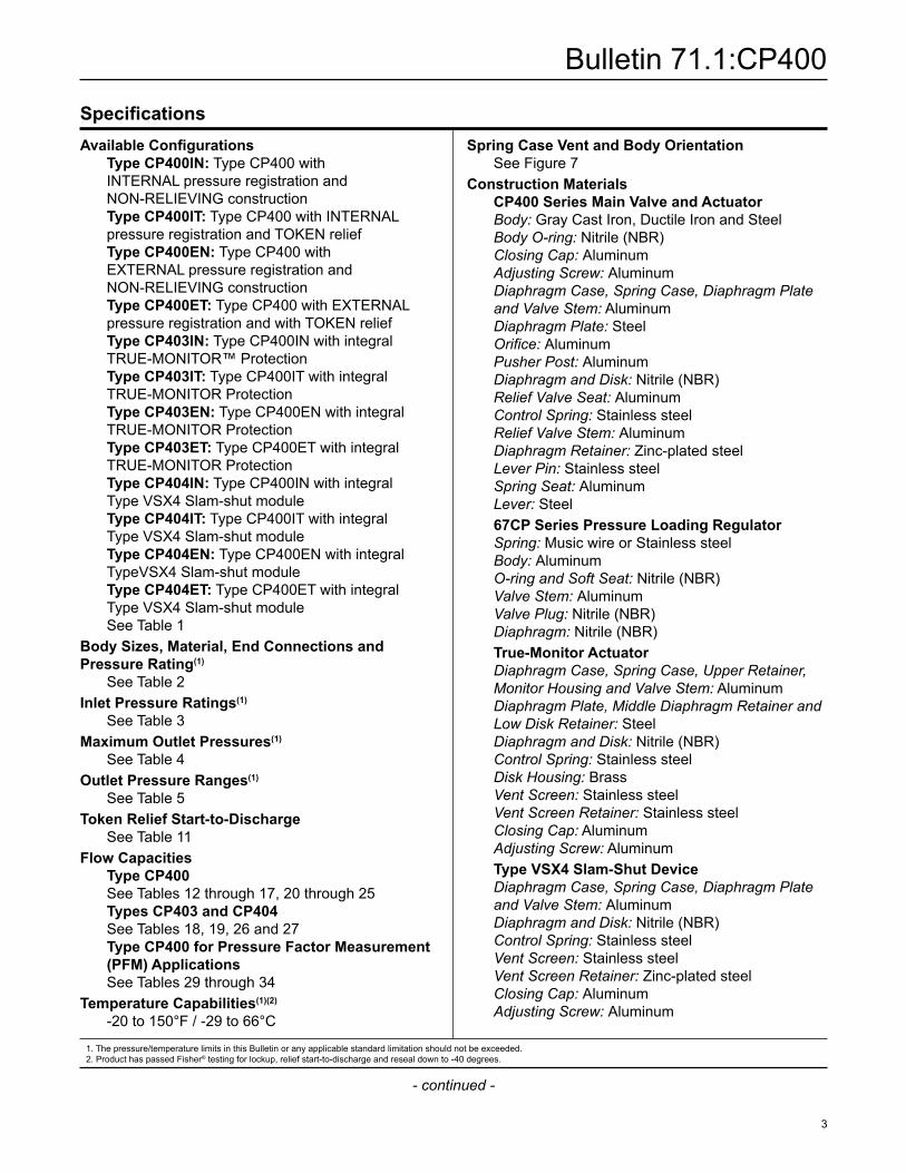
Table 3. Inlet Pressure Ratings and Flow and Sizing Coefficients
ORIFICE SIZE MAXIMuM OPERATING INLET PRESSuRE WIDE-OPEN FLOW COEFFICIENTSC1
IEC SIZING COEFFICIENTSIn. mm psig bar Cg Cv XT FD FL
3/16 4.8 125 8.6 27 0.97 27.7 0.50 0.91
0.89
1/4 6.4 125 8.6 50 1.77 28.2 0.50 0.923/8 9.5 80 5.5 113 3.72 30.4 0.58 0.891/2 13 60 4.1 182 5.61 32.4 0.66 0.825/8 16 50 3.4 284 7.26 39.1 0.97 0.743/4 19 40 2.8 356 9.83 36.2 0.83 0.72
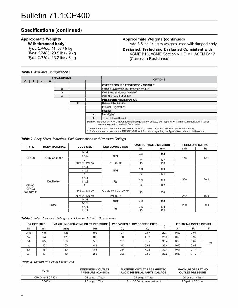
TyPE NuMBER OPTIONSC P 4 0OVERPRESSuRE PROTECTION MODuLE
0 Without Overpressure Protection Module3 With Integral Monitor Module(1)
4 With Slam-shut Module(2)
PRESSuRE REGISTRATIONE External RegistrationI Internal Registration
RELIEFN Non-ReliefT Token Internal Relief
Example: Type number CP404IT: CP400 Series regulator constructed with Type VSX4 Slam-shut module, with Internal pressure registration and with Token relief.
1. Reference Instruction Manual D103126X012 for information regarding the Integral Monitor module.2. Reference Instruction Manual D103127X012 for information regarding the Type VSX4 safety shutoff module.
Table 1. Available Configurations
Table 2. Body Sizes, Materials, End Connections and Pressure Ratings
TyPE BODy MATERIAL BODy SIZE END CONNECTION FACE-TO-FACE DIMENSION PRESSuRE RATINGIn. mm psig bar
CP400 Gray Cast Iron
1-1/4NPT
4.5 114175 12.1
1-1/22 5 127
NPS 2 / DN 50 CL125 FF 10 254
CP400, CP403
and CP404
Ductile Iron
1-1/4 NPT
4.5 114
290 20.0
1-1/2 2 5 127
1-1/4Rp
4.5 1141-1/2
2 5 127
NPS 2 / DN 50 CL125 FF / CL150 FF10 254
NPS 2 / DN 50 PN 10/16 232 16.0
Steel
1-1/4 NPT 4.5 114
290 20.01-1/2 1-1/4
Rp7.5 191
1-1/2 10 254
TyPE EMERGENCy OuTLET PRESSuRE (CASING)
MAXIMuM OuTLET PRESSuRE TO AVOID INTERNAL PARTS DAMAGE
MAXIMuM OPERATING OuTLET PRESSuRE
CP400 and CP404 25 psig / 1.7 bar 25 psig / 1.7 bar 20 psig / 1.4 barCP403 25 psig / 1.7 bar 5 psi / 0.34 bar over setpoint 7.5 psig / 0.52 bar
Table 4. Maximum Outlet Pressures
Specifications (continued)
Approximate Weights With threaded body Type CP400: 11 lbs / 5 kg Type CP403: 20.5 lbs / 9 kg Type CP404: 13.2 lbs / 6 kg
Approximate Weights (continued) Add 8.6 lbs / 4 kg to weights listed with flanged bodyDesigned, Tested and Evaluated Consistent with: ASME B16, ASME Section VIII DIV I, ASTM B117
(Corrosion Resistance)
Bulletin 71.1:CP400
5
M1065
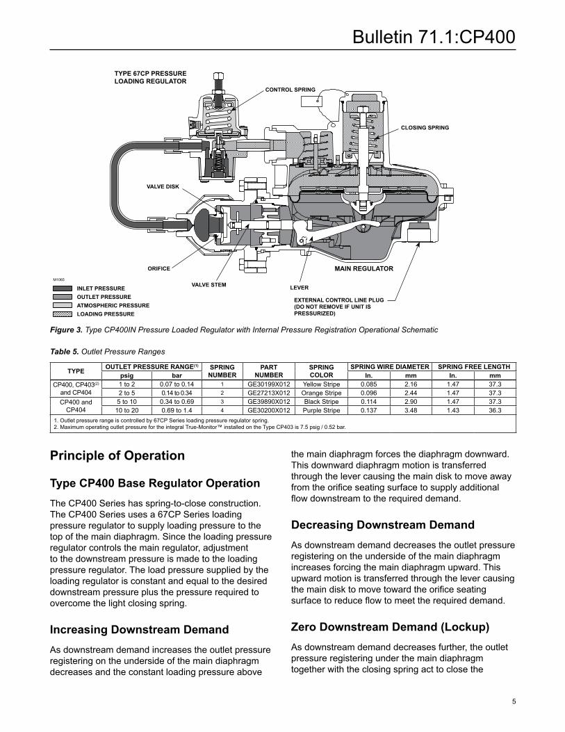
Figure 3. Type CP400IN Pressure Loaded Regulator with Internal Pressure Registration Operational Schematic
Type CP400IT Pressure Loaded Regulator with Token Relief
M10
82
January 2008 Type CP400IT
INLET PRESSUREOUTLET PRESSUREATMOSPHERIC PRESSURELOADING PRESSURE
INLET PRESSuREOuTLET PRESSuREATMOSPHERIC PRESSuRELOADING PRESSuRE
TyPE 67CP PRESSuRE LOADING REGuLATOR
MAIN REGuLATOR
EXTERNAL CONTROL LINE PLuG (DO NOT REMOVE IF uNIT IS PRESSuRIZED)
CONTROL SPRING
CLOSING SPRING
LEVER
VALVE DISK
VALVE STEM
ORIFICE
Principle of Operation
Type CP400 Base Regulator OperationThe CP400 Series has spring-to-close construction. The CP400 Series uses a 67CP Series loading pressure regulator to supply loading pressure to the top of the main diaphragm. Since the loading pressure regulator controls the main regulator, adjustment to the downstream pressure is made to the loading pressure regulator. The load pressure supplied by the loading regulator is constant and equal to the desired downstream pressure plus the pressure required to overcome the light closing spring.
Increasing Downstream DemandAs downstream demand increases the outlet pressure registering on the underside of the main diaphragm decreases and the constant loading pressure above
the main diaphragm forces the diaphragm downward. This downward diaphragm motion is transferred through the lever causing the main disk to move away from the orifice seating surface to supply additional flow downstream to the required demand.
Decreasing Downstream DemandAs downstream demand decreases the outlet pressure registering on the underside of the main diaphragm increases forcing the main diaphragm upward. This upward motion is transferred through the lever causing the main disk to move toward the orifice seating surface to reduce flow to meet the required demand.
Zero Downstream Demand (Lockup)As downstream demand decreases further, the outlet pressure registering under the main diaphragm together with the closing spring act to close the
Table 5. Outlet Pressure Ranges
TyPE OuTLET PRESSuRE RANGE(1) SPRING NuMBER
PART NuMBER
SPRING COLOR
SPRING WIRE DIAMETER SPRING FREE LENGTHpsig bar In. mm In. mm
CP400, CP403(2) and CP404
1 to 2 0.07 to 0.14 1 GE30199X012 Yellow Stripe 0.085 2.16 1.47 37.32 to 5 0.14 to 0.34 2 GE27213X012 Orange Stripe 0.096 2.44 1.47 37.3
CP400 and CP404
5 to 10 0.34 to 0.69 3 GE39890X012 Black Stripe 0.114 2.90 1.47 37.310 to 20 0.69 to 1.4 4 GE30200X012 Purple Stripe 0.137 3.48 1.43 36.3
1. Outlet pressure range is controlled by 67CP Series loading pressure regulator spring.2. Maximum operating outlet pressure for the integral True-Monitor™ installed on the Type CP403 is 7.5 psig / 0.52 bar.
Bulletin 71.1:CP400
6
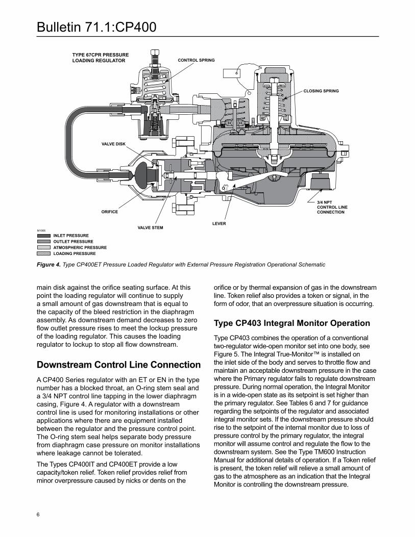
orifice or by thermal expansion of gas in the downstream line. Token relief also provides a token or signal, in the form of odor, that an overpressure situation is occurring.
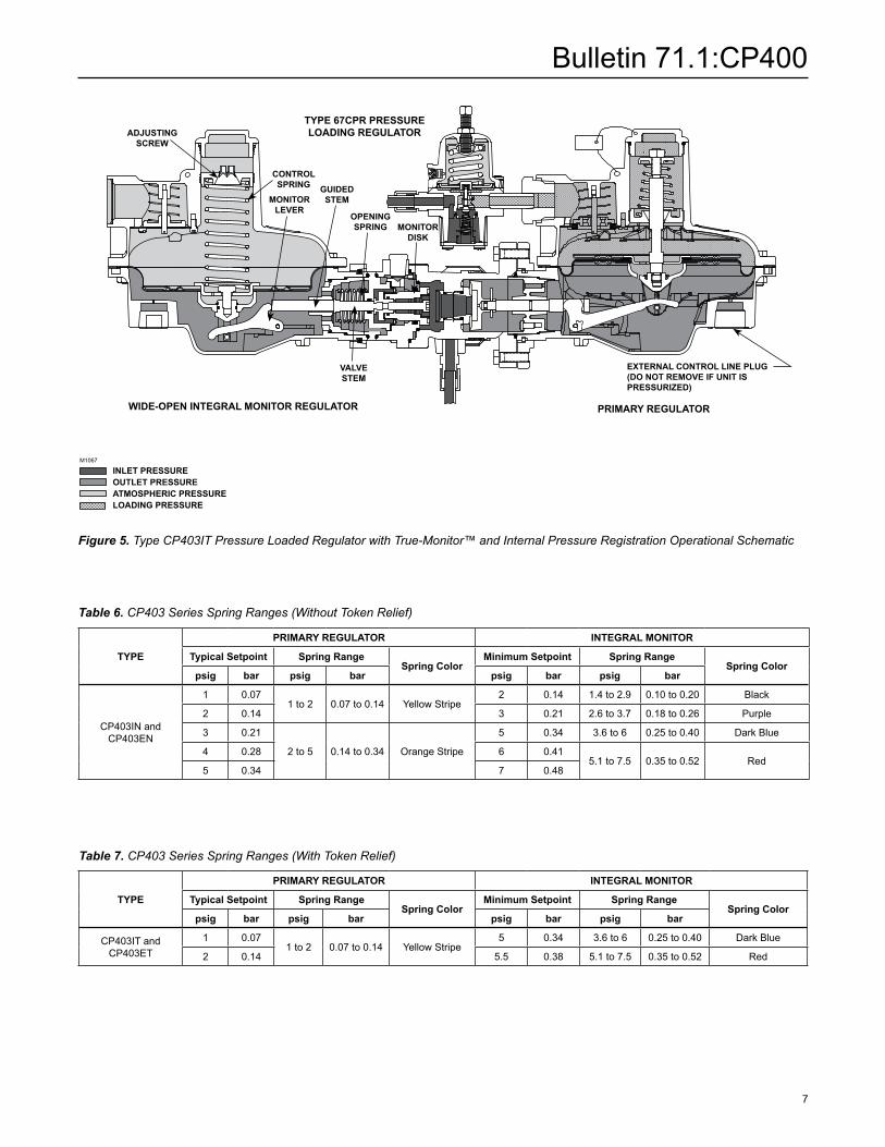
Type CP403 Integral Monitor OperationType CP403 combines the operation of a conventional two-regulator wide-open monitor set into one body, see Figure 5. The Integral True-Monitor™ is installed on the inlet side of the body and serves to throttle flow and maintain an acceptable downstream pressure in the case where the Primary regulator fails to regulate downstream pressure. During normal operation, the Integral Monitor is in a wide-open state as its setpoint is set higher than the primary regulator. See Tables 6 and 7 for guidance regarding the setpoints of the regulator and associated integral monitor sets. If the downstream pressure should rise to the setpoint of the internal monitor due to loss of pressure control by the primary regulator, the integral monitor will assume control and regulate the flow to the downstream system. See the Type TM600 Instruction Manual for additional details of operation. If a Token relief is present, the token relief will relieve a small amount of gas to the atmosphere as an indication that the Integral Monitor is controlling the downstream pressure.
main disk against the orifice seating surface. At this point the loading regulator will continue to supply a small amount of gas downstream that is equal to the capacity of the bleed restriction in the diaphragm assembly. As downstream demand decreases to zero flow outlet pressure rises to meet the lockup pressure of the loading regulator. This causes the loading regulator to lockup to stop all flow downstream.
Downstream Control Line ConnectionA CP400 Series regulator with an ET or EN in the type number has a blocked throat, an O-ring stem seal and a 3/4 NPT control line tapping in the lower diaphragm casing, Figure 4. A regulator with a downstream control line is used for monitoring installations or other applications where there are equipment installed between the regulator and the pressure control point. The O-ring stem seal helps separate body pressure from diaphragm case pressure on monitor installations where leakage cannot be tolerated.The Types CP400IT and CP400ET provide a low capacity/token relief. Token relief provides relief from minor overpressure caused by nicks or dents on the
Figure 4. Type CP400ET Pressure Loaded Regulator with External Pressure Registration Operational Schematic
Type CP400ET Pressure Loaded Regulator with Token Relief
M10
83
January 2008 Type CP400ET
INLET PRESSUREOUTLET PRESSUREATMOSPHERIC PRESSURELOADING PRESSURE
INLET PRESSuREOuTLET PRESSuREATMOSPHERIC PRESSuRELOADING PRESSuRE
M1066
TyPE 67CPR PRESSuRE LOADING REGuLATOR
3/4 NPT CONTROL LINE CONNECTION
CONTROL SPRING
CLOSING SPRING
LEVER
VALVE DISK
VALVE STEM
ORIFICE
Bulletin 71.1:CP400
7
Figure 5. Type CP403IT Pressure Loaded Regulator with True-Monitor™ and Internal Pressure Registration Operational Schematic
TyPE 67CPR PRESSuRELOADING REGuLATOR
WIDE-OPEN INTEGRAL MONITOR REGuLATOR PRIMARy REGuLATOR
ADJuSTING SCREW
CONTROLSPRING
MONITOR LEVER
GuIDEDSTEM
MONITORDISK
VALVESTEM
INLET PRESSuREOuTLET PRESSuREATMOSPHERIC PRESSuRELOADING PRESSuRE
M1067
EXTERNAL CONTROL LINE PLuG (DO NOT REMOVE IF uNIT IS PRESSuRIZED)
OPENING SPRING
Table 6. CP403 Series Spring Ranges (Without Token Relief)
TyPE
PRIMARy REGuLATOR INTEGRAL MONITOR
Typical Setpoint Spring RangeSpring Color
Minimum Setpoint Spring RangeSpring Color
psig bar psig bar psig bar psig bar
CP403IN and CP403EN
1 0.071 to 2 0.07 to 0.14 Yellow Stripe
2 0.14 1.4 to 2.9 0.10 to 0.20 Black
2 0.14 3 0.21 2.6 to 3.7 0.18 to 0.26 Purple
3 0.21
2 to 5 0.14 to 0.34 Orange Stripe
5 0.34 3.6 to 6 0.25 to 0.40 Dark Blue
4 0.28 6 0.415.1 to 7.5 0.35 to 0.52 Red
5 0.34 7 0.48
Table 7. CP403 Series Spring Ranges (With Token Relief)
TyPE
PRIMARy REGuLATOR INTEGRAL MONITOR
Typical Setpoint Spring RangeSpring Color
Minimum Setpoint Spring RangeSpring Color
psig bar psig bar psig bar psig bar
CP403IT and CP403ET
1 0.071 to 2 0.07 to 0.14 Yellow Stripe
5 0.34 3.6 to 6 0.25 to 0.40 Dark Blue
2 0.14 5.5 0.38 5.1 to 7.5 0.35 to 0.52 Red
Bulletin 71.1:CP400
8
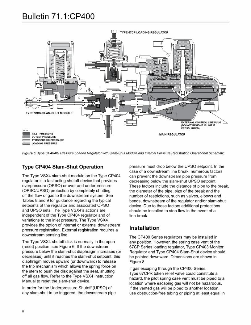
Figure 6. Type CP404IN Pressure Loaded Regulator with Slam-Shut Module and Internal Pressure Registration Operational Schematic
INLET PRESSuREOuTLET PRESSuREATMOSPHERIC PRESSuRELOADING PRESSuRE
M1068
TyPE VSX4 SLAM-SHuT MODuLE
MAIN REGuLATOR
TyPE 67CP LOADING REGuLATOR
EXTERNAL CONTROL LINE PLuG (DO NOT REMOVE IF uNIT IS PRESSuRIZED)
Type CP404 Slam-Shut OperationThe Type VSX4 slam-shut module on the Type CP404 regulator is a fast acting shutoff device that provides overpressure (OPSO) or over and underpressure (OPSO/UPSO) protection by completely shutting off the flow of gas to the downstream system. See Tables 8 and 9 for guidance regarding the typical setpoints of the regulator and associated OPSO and UPSO sets. The Type VSX4’s actions are independent of the Type CP404 regulator and of variations to the inlet pressure. The Type VSX4 provides the option of internal or external downstream pressure registration. External registration requires a downstream sensing line.The Type VSX4 shutoff disk is normally in the open (reset) position, see Figure 6. If the downstream pressure below the slam-shut diaphragm increases (or decreases) until it reaches the slam-shut setpoint, this diaphragm moves upward (or downward) to release the trip mechanism which allows the spring force on the stem to push the disk against the seat, shutting off all gas flow. Refer to the Type VSX4 Instruction Manual to reset the slam-shut device.In order for the Underpressure Shutoff (UPSO) of any slam-shut to be triggered, the downstream pipe
pressure must drop below the UPSO setpoint. In the case of a downstream line break, numerous factors can prevent the downstream pipe pressure from decreasing below the slam-shut UPSO setpoint. These factors include the distance of pipe to the break, the diameter of the pipe, size of the break and the number of restrictions, such as valves, elbows and bends, downstream of the regulator and/or slam-shut device. Due to these factors additional protections should be installed to stop flow in the event of a line break.
InstallationThe CP400 Series regulators may be installed in any position. However, the spring case vent of the 67CP Series loading regulator, Type CP403 Monitor Regulator and Type CP404 Slam-Shut device should be pointed downward. Dimensions are shown in Figure 8.If gas escaping through the CP400 Series, Type 67CPR token relief valve could constitute a hazard, the pilot spring case vent must be piped to a location where escaping gas will not be hazardous. If the vented gas will be piped to another location, use obstruction-free tubing or piping at least equal in
Bulletin 71.1:CP400
9
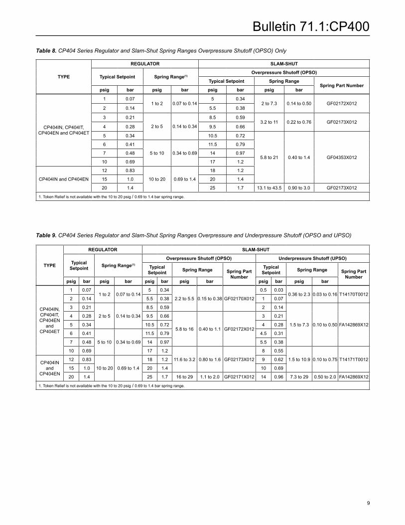
Table 8. CP404 Series Regulator and Slam-Shut Spring Ranges Overpressure Shutoff (OPSO) Only
TyPE
REGuLATOR SLAM-SHuT
Typical Setpoint Spring Range(1)Overpressure Shutoff (OPSO)
Typical Setpoint Spring RangeSpring Part Number
psig bar psig bar psig bar psig bar
CP404IN, CP404IT, CP404EN and CP404ET
1 0.071 to 2 0.07 to 0.14
5 0.342 to 7.3 0.14 to 0.50 GF02172X012
2 0.14 5.5 0.38
3 0.21
2 to 5 0.14 to 0.34
8.5 0.593.2 to 11 0.22 to 0.76 GF02173X012
4 0.28 9.5 0.66
5 0.34 10.5 0.72
5.8 to 21 0.40 to 1.4 GF04353X012
6 0.41
5 to 10 0.34 to 0.69
11.5 0.79
7 0.48 14 0.97
10 0.69 17 1.2
CP404IN and CP404EN
12 0.83
10 to 20 0.69 to 1.4
18 1.2
15 1.0 20 1.4
20 1.4 25 1.7 13.1 to 43.5 0.90 to 3.0 GF02173X012
1. Token Relief is not available with the 10 to 20 psig / 0.69 to 1.4 bar spring range.
Table 9. CP404 Series Regulator and Slam-Shut Spring Ranges Overpressure and Underpressure Shutoff (OPSO and UPSO)
TyPE
REGuLATOR SLAM-SHuT
Typical Setpoint Spring Range(1)
Overpressure Shutoff (OPSO) underpressure Shutoff (uPSO)
Typical Setpoint Spring Range Spring Part
Number
Typical Setpoint Spring Range Spring Part
Numberpsig bar psig bar psig bar psig bar psig bar psig bar
CP404IN, CP404IT, CP404EN
and CP404ET
1 0.071 to 2 0.07 to 0.14
5 0.34
2.2 to 5.5 0.15 to 0.38 GF02170X012
0.5 0.030.36 to 2.3 0.03 to 0.16 T14170T0012
2 0.14 5.5 0.38 1 0.07
3 0.21
2 to 5 0.14 to 0.34
8.5 0.59 2 0.14
1.5 to 7.3 0.10 to 0.50 FA142869X12
4 0.28 9.5 0.66
5.8 to 16 0.40 to 1.1 GF02172X012
3 0.21
5 0.34 10.5 0.72 4 0.28
6 0.41
5 to 10 0.34 to 0.69
11.5 0.79 4.5 0.31
7 0.48 14 0.97 5.5 0.38
10 0.69 17 1.2
11.6 to 3.2 0.80 to 1.6 GF02173X012
8 0.55
1.5 to 10.9 0.10 to 0.75 T14171T0012 CP404IN
and CP404EN
12 0.83
10 to 20 0.69 to 1.4
18 1.2 9 0.62
15 1.0 20 1.4 10 0.69
20 1.4 25 1.7 16 to 29 1.1 to 2.0 GF02171X012 14 0.96 7.3 to 29 0.50 to 2.0 FA142869X12
1. Token Relief is not available with the 10 to 20 psig / 0.69 to 1.4 bar spring range.

Bulletin 71.1:CP400
10
size to the vent, and the end of the vent pipe must be protected from anything that might clog it. Regulators with External Registration require the use of an external control line. Vent and Body orientation is shown in Figure 7. Dimensions are shown in Figure 8.
Overpressure ProtectionThe CP400 Series regulators have outlet pressure ratings that are lower than their inlet pressure ratings. A pressure relieving or pressure limiting device is needed for Types CP400IN, CP400EN, CP400IT and CP400ET if inlet pressure can exceed the outlet pressure rating as these regulators do not have standard internal relief, high outlet pressure shutoff or integral slam-shut module.
Token ReliefTypes with a “T” in the type number, e.g., Type CP400IT provide an optional small capacity or token relief located in the Type 67CPR to relieve minor overpressure caused by thermal expansion or minor nicks in the orifice or disk.
Integral True-Monitor ProtectionTypes CP403IN, CP403EN, CP403IT and CP403ET combine the operation of a conventional two-regulator
wide-open monitor set into one body. The Integral True-Monitor is installed on the inlet side of the body and serves to throttle flow and maintain an acceptable downstream pressure in the case where the primary regulator fails to regulate. Unlike multiple seat designs that rely on the primary regulator for all failure modes, the Type CP403 provides protection from a wide variety of failures that could cause the primary regulator not to regulate downstream pressure. Table 10 shows a comparison between the Integral True-Monitor protection and the protection offered by an additional seat.
Pressure Registration
The Integral True-Monitor has the options for internal pressure registration and external registration, denoted by the “I” and “E” in the type number, respectively. The method of pressure registration is dependent on the registration of the primary regulator, see Table 1. For example, if the primary regulator’s registration is internal, then the wide-open monitor regulator’s registration should either be internal or external. If the primary regulator’s registration is external, then the wide-open monitor regulator’s pressure registration must be external.
Token Relief
An optional token relief may be installed on the primary regulator of the Type CP403, denoted by the “T” in the type number, for example, Type CP403IT. The token
CP403 SERIES TRuE-MONITOR™ PROTECTION ADDITIONAL SEAT PROTECTION
Damage/nick on seat X X
Damage to disk X X
Damage or disconnected lever X - - - -
Damage to diaphragm X - - - -
Blocked or broken registration toPrimary regulator(1) X - - - -
1. For external pressure registered units, in order to gain True-Monitor Protection in the case of damaged or broken sense line, it is required that the Primary and Integral Wide-Open Monitor do not share downstream sense lines.
Table 10. Type CP403 Overpressure Protection Benefits vs. Additional Seat Protection
SETPOINT(1)
SPRING COLOR SPRING PARTNuMBER
START-TO-DISCHARGE PRESSuRERANGE ABOVE SETPOINT
psig bar psig mbar
1 to 2 0.07 to 0.14 Yellow Stripe GE30199X012 1 to 3.5 69 to 241
2 to 5 0.14 to 0.34 Orange Stripe GE27213X012 1.75 to 5.5 121 to 379
5 to 10 0.34 to 0.69 Black Stripe GE39890X012 2.5 to 6.75 172 to 465
1. Outlet pressure range is controlled by 67CP Series pressure loading regulator spring. Only the 1 to 2, 2 to 5 and 5 to 10 psig / 0.07 to 0.14, 0.14 to 0.34 and 0.34 to 0.69 bar spring ranges are available with Token Relief.
Table 11. Token Relief Valve Start-to-Discharge Pressure Above Setpoint

Bulletin 71.1:CP400
11
relief will be activated when the pressure rises and activates the monitoring regulator in order to provide an indication that the monitor is controlling flow instead of the primary regulator.
Integral Type VSX4 Slam-Shut ModuleThe Type VSX4 slam-shut module on the CP404 Series regulator is a fast acting safety shutoff device that provides overpressure (OPSO) or over and underpressure (OPSO/UPSO) protection by completely shutting off the flow of gas to the downstream system. The Type VSX4’s actions are independent of the CP404 Series regulator and of variations to the inlet pressure. The Type VSX4 provides the option of internal or external downstream pressure registration, see Figure 6. External registration requires a downstream sensing line.The shutoff disk is normally in the open (reset) position. If the pressure below the diaphragm increases (or decreases) reaching the Type VSX4 setpoint, the diaphragm will travel upwards (or downwards) to release the trip mechanism which allows the spring force on the stem to push the disk against the seat, shutting off all gas flow. The manual reset has an internal bypass to equalize the reset pressure on either side on the shutoff disk.Overpressuring any portion of a regulator or associated equipment may cause personal injury, leakage or property damage due to bursting of pressure-containing parts or explosion of accumulated gas. Provide appropriate pressure relieving or pressure limiting devices to ensure that the limits in the Specifications section is not exceeded. Regulator operation within ratings does not prevent the possibility of damage from external sources or from debris in the pipeline.Refer to the relief sizing coefficients and the Capacity Information section to determine the required relief valve capacity.
Capacity InformationTables 12 to 27 and 29 to 34 give the CP400 Series natural gas regulating capacities at selected inlet pressures, outlet pressure settings and body outlet sizes. Tables 29 through 34 provide capacities specifically for Pressure Factor Measurement (PFM) applications. Flows are in SCFH (60°F and 14.7 psia) and Nm³/h (0°C and 1.01325 bar) of 0.6 specific gravity natural gas. To determine equivalent capacities for air, propane, butane or nitrogen, multiply
the capacity number in the tables by the following appropriate conversion factor: 0.775 for air, 0.628 for propane, 0.548 for butane or 0.789 for nitrogen. For gases of other specific gravities, multiply the given capacity by 0.775 and divide by the square root of the appropriate specific gravity.
Relief Sizing
For critical flow:
To determine wide-open flow capacities for relief sizing of 0.6 specific gravity natural gas at 60°F at critical pressure drops (absolute outlet pressure equal to approximately one-half or less than one-half of the absolute inlet pressure), use the following formula:
Q = P1abs(Cg)(1.29)
For subcritical flow:
If pressure drops are lower than critical (absolute outlet pressure greater than approximately one-half the absolute inlet pressure), use the following formula and convert according to the factors in the preceding paragraph if necessary:
Q = CgP1SIN520GT
3417C1
∆PP1
DEG
where: C1 = Cg/Cv (see Table 3) Cg = Gas sizing coefficient (see Table 3) G = Gas specific gravity (air = 1.0) P1 = Regulator inlet pressure, psia ∆P = Pressure drop across regulator, psi Q = Gas flow rate, SCFH T = Absolute temperature of gas at inlet, °Rankine
NoteDue to boost, the above formulas cannot be used to obtain correct regulating capacities for regulators with internal registration.
The published capacities were obtained using inlet and outlet piping the same size as the regulator body size.
Bulletin 71.1:CP400
12
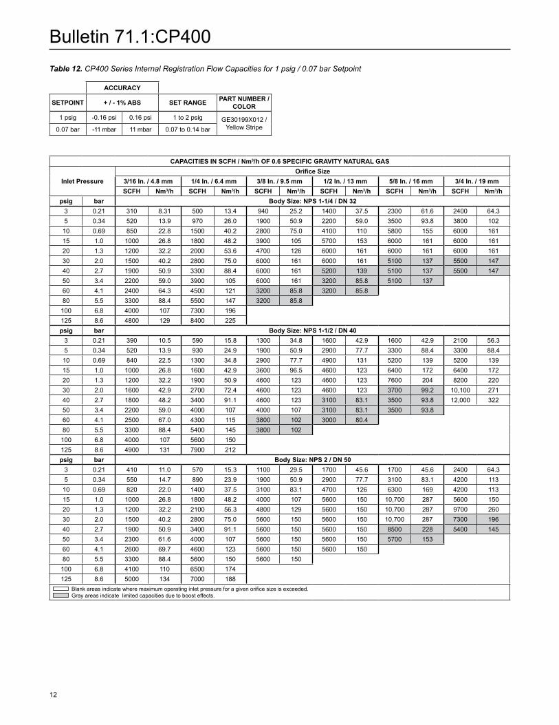
Table 12. CP400 Series Internal Registration Flow Capacities for 1 psig / 0.07 bar Setpoint
ACCuRACy
SETPOINT + / - 1% ABS SET RANGE PART NuMBER / COLOR
1 psig -0.16 psi 0.16 psi 1 to 2 psig GE30199X012 /Yellow Stripe0.07 bar -11 mbar 11 mbar 0.07 to 0.14 bar
CAPACITIES IN SCFH / Nm3/h OF 0.6 SPECIFIC GRAVITy NATuRAL GAS
Inlet PressureOrifice Size
3/16 In. / 4.8 mm 1/4 In. / 6.4 mm 3/8 In. / 9.5 mm 1/2 In. / 13 mm 5/8 In. / 16 mm 3/4 In. / 19 mmSCFH Nm3/h SCFH Nm3/h SCFH Nm3/h SCFH Nm3/h SCFH Nm3/h SCFH Nm3/h
psig bar Body Size: NPS 1-1/4 / DN 323 0.21 310 8.31 500 13.4 940 25.2 1400 37.5 2300 61.6 2400 64.35 0.34 520 13.9 970 26.0 1900 50.9 2200 59.0 3500 93.8 3800 102
10 0.69 850 22.8 1500 40.2 2800 75.0 4100 110 5800 155 6000 16115 1.0 1000 26.8 1800 48.2 3900 105 5700 153 6000 161 6000 16120 1.3 1200 32.2 2000 53.6 4700 126 6000 161 6000 161 6000 16130 2.0 1500 40.2 2800 75.0 6000 161 6000 161 5100 137 5500 14740 2.7 1900 50.9 3300 88.4 6000 161 5200 139 5100 137 5500 14750 3.4 2200 59.0 3900 105 6000 161 3200 85.8 5100 13760 4.1 2400 64.3 4500 121 3200 85.8 3200 85.880 5.5 3300 88.4 5500 147 3200 85.8100 6.8 4000 107 7300 196125 8.6 4800 129 8400 225psig bar Body Size: NPS 1-1/2 / DN 40
3 0.21 390 10.5 590 15.8 1300 34.8 1600 42.9 1600 42.9 2100 56.35 0.34 520 13.9 930 24.9 1900 50.9 2900 77.7 3300 88.4 3300 88.410 0.69 840 22.5 1300 34.8 2900 77.7 4900 131 5200 139 5200 13915 1.0 1000 26.8 1600 42.9 3600 96.5 4600 123 6400 172 6400 17220 1.3 1200 32.2 1900 50.9 4600 123 4600 123 7600 204 8200 22030 2.0 1600 42.9 2700 72.4 4600 123 4600 123 3700 99.2 10,100 27140 2.7 1800 48.2 3400 91.1 4600 123 3100 83.1 3500 93.8 12,000 32250 3.4 2200 59.0 4000 107 4000 107 3100 83.1 3500 93.860 4.1 2500 67.0 4300 115 3800 102 3000 80.480 5.5 3300 88.4 5400 145 3800 102100 6.8 4000 107 5600 150125 8.6 4900 131 7900 212psig bar Body Size: NPS 2 / DN 50
3 0.21 410 11.0 570 15.3 1100 29.5 1700 45.6 1700 45.6 2400 64.35 0.34 550 14.7 890 23.9 1900 50.9 2900 77.7 3100 83.1 4200 11310 0.69 820 22.0 1400 37.5 3100 83.1 4700 126 6300 169 4200 11315 1.0 1000 26.8 1800 48.2 4000 107 5600 150 10,700 287 5600 15020 1.3 1200 32.2 2100 56.3 4800 129 5600 150 10,700 287 9700 26030 2.0 1500 40.2 2800 75.0 5600 150 5600 150 10,700 287 7300 19640 2.7 1900 50.9 3400 91.1 5600 150 5600 150 8500 228 5400 14550 3.4 2300 61.6 4000 107 5600 150 5600 150 5700 15360 4.1 2600 69.7 4600 123 5600 150 5600 15080 5.5 3300 88.4 5600 150 5600 150100 6.8 4100 110 6500 174125 8.6 5000 134 7000 188
Blank areas indicate where maximum operating inlet pressure for a given orifice size is exceeded. Gray areas indicate limited capacities due to boost effects.

Bulletin 71.1:CP400
13
Table 13. CP400 Series Internal Registration Flow Capacities for 2 psig / 0.14 bar Setpoint
ACCuRACy
SETPOINT + / - 1% ABS SET RANGE PART NuMBER / COLOR
2 psig -0.17 psi 0.17 psi 1 to 2 psig GE30199X012 / Yellow Stripe 0.14 bar -12 mbar 12 mbar 0.07 to 0.14 bar
CAPACITIES IN SCFH / Nm3/h OF 0.6 SPECIFIC GRAVITy NATuRAL GAS
Inlet PressureOrifice Size
3/16 In. / 4.8 mm 1/4 In. / 6.4 mm 3/8 In. / 9.5 mm 1/2 In. / 13 mm 5/8 In. / 16 mm 3/4 In. / 19 mmSCFH Nm3/h SCFH Nm3/h SCFH Nm3/h SCFH Nm3/h SCFH Nm3/h SCFH Nm3/h
psig bar Body Size: NPS 1-1/4 / DN 325 0.34 470 12.6 970 26.0 1400 37.5 1900 50.9 2700 72.4 3800 102
10 0.69 800 21.4 1300 34.8 2800 75.0 4100 110 5200 139 7100 19015 1.0 1000 26.8 1800 48.2 3800 102 5000 134 5700 153 7200 19320 1.3 1200 32.2 2100 56.3 4700 126 5000 134 5700 153 7200 19330 2.0 1500 40.2 2700 72.4 6000 161 3200 85.8 5700 153 7200 19340 2.7 1900 50.9 3300 88.4 6000 161 3200 85.8 5700 153 7200 19350 3.4 2200 59.0 3900 105 6000 161 3200 85.8 5700 15360 4.1 2500 67.0 4200 113 4500 121 3200 85.880 5.5 3300 88.4 4200 113 2900 77.7
100 6.8 3300 88.4 4200 113125 8.6 3300 88.4 4200 113psig bar Body Size: NPS 1-1/2 / DN 40
5 0.34 420 11.3 820 22.0 1900 50.9 350 9.38 2700 72.4 2800 75.010 0.69 810 21.7 1400 37.5 3200 85.8 3900 105 5300 142 6400 17215 1.0 1000 26.8 1500 40.2 4000 107 5600 150 7000 188 9000 24120 1.3 1100 29.5 2100 56.3 4700 126 7100 190 8400 225 9700 26030 2.0 1500 40.2 2600 69.7 6000 161 7400 198 8400 225 10,200 27340 2.7 1900 50.9 3200 85.8 7400 198 3700 99.2 8400 225 12,100 32450 3.4 2100 56.3 3900 105 7400 198 3200 85.8 4200 11360 4.1 2400 64.3 4700 126 7400 198 3200 85.880 5.5 3300 88.4 6000 161 7400 198
100 6.8 4100 110 6500 174125 8.6 4900 131 6500 174psig bar Body Size: NPS 2 / DN 50
5 0.34 530 14.2 850 22.8 1400 37.5 2100 56.3 3000 80.4 3400 91.110 0.69 820 22.0 1500 40.2 3100 83.1 4400 118 5700 153 9500 25515 1.0 1000 26.8 1800 48.2 4000 107 6100 163 10,100 271 10,100 27120 1.3 1200 32.2 2100 56.3 4600 123 7100 190 10,100 271 10,100 27130 2.0 1500 40.2 2700 72.4 6000 161 7100 190 10,100 271 8600 23040 2.7 1900 50.9 3300 88.4 6000 161 7100 190 6200 166 6700 18050 3.4 2200 59.0 4000 107 6000 161 7100 190 4900 13160 4.1 2600 69.7 4700 126 6000 161 7100 19080 5.5 3400 91.1 6000 161 6000 161
100 6.8 4100 110 6000 161125 8.6 5000 134 6000 161
Blank areas indicate where maximum operating inlet pressure for a given orifice size is exceeded. Gray areas indicate limited capacities due to boost effects.
Bulletin 71.1:CP400
14
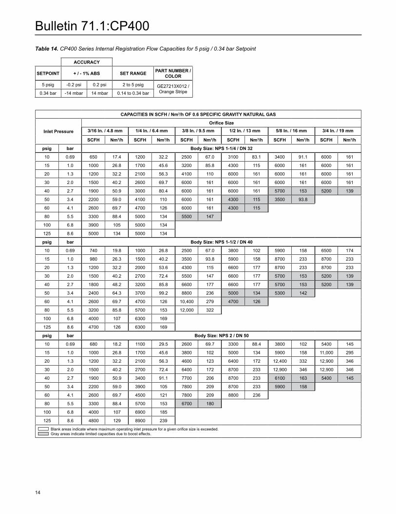
Table 14. CP400 Series Internal Registration Flow Capacities for 5 psig / 0.34 bar Setpoint
ACCuRACy
SETPOINT + / - 1% ABS SET RANGE PART NuMBER / COLOR
5 psig -0.2 psi 0.2 psi 2 to 5 psig GE27213X012 / Orange Stripe0.34 bar -14 mbar 14 mbar 0.14 to 0.34 bar
CAPACITIES IN SCFH / Nm3/h OF 0.6 SPECIFIC GRAVITy NATuRAL GAS
Inlet Pressure
Orifice Size3/16 In. / 4.8 mm 1/4 In. / 6.4 mm 3/8 In. / 9.5 mm 1/2 In. / 13 mm 5/8 In. / 16 mm 3/4 In. / 19 mm
SCFH Nm3/h SCFH Nm3/h SCFH Nm3/h SCFH Nm3/h SCFH Nm3/h SCFH Nm3/h
psig bar Body Size: NPS 1-1/4 / DN 32
10 0.69 650 17.4 1200 32.2 2500 67.0 3100 83.1 3400 91.1 6000 161
15 1.0 1000 26.8 1700 45.6 3200 85.8 4300 115 6000 161 6000 161
20 1.3 1200 32.2 2100 56.3 4100 110 6000 161 6000 161 6000 161
30 2.0 1500 40.2 2600 69.7 6000 161 6000 161 6000 161 6000 161
40 2.7 1900 50.9 3000 80.4 6000 161 6000 161 5700 153 5200 139
50 3.4 2200 59.0 4100 110 6000 161 4300 115 3500 93.8
60 4.1 2600 69.7 4700 126 6000 161 4300 115
80 5.5 3300 88.4 5000 134 5500 147
100 6.8 3900 105 5000 134
125 8.6 5000 134 5000 134
psig bar Body Size: NPS 1-1/2 / DN 40
10 0.69 740 19.8 1000 26.8 2500 67.0 3800 102 5900 158 6500 174
15 1.0 980 26.3 1500 40.2 3500 93.8 5900 158 8700 233 8700 233
20 1.3 1200 32.2 2000 53.6 4300 115 6600 177 8700 233 8700 233
30 2.0 1500 40.2 2700 72.4 5500 147 6600 177 5700 153 5200 139
40 2.7 1800 48.2 3200 85.8 6600 177 6600 177 5700 153 5200 139
50 3.4 2400 64.3 3700 99.2 8800 236 5000 134 5300 142
60 4.1 2600 69.7 4700 126 10,400 279 4700 126
80 5.5 3200 85.8 5700 153 12,000 322
100 6.8 4000 107 6300 169
125 8.6 4700 126 6300 169
psig bar Body Size: NPS 2 / DN 50
10 0.69 680 18.2 1100 29.5 2600 69.7 3300 88.4 3800 102 5400 145
15 1.0 1000 26.8 1700 45.6 3800 102 5000 134 5900 158 11,000 295
20 1.3 1200 32.2 2100 56.3 4600 123 6400 172 12,400 332 12,900 346
30 2.0 1500 40.2 2700 72.4 6400 172 8700 233 12,900 346 12,900 346
40 2.7 1900 50.9 3400 91.1 7700 206 8700 233 6100 163 5400 145
50 3.4 2200 59.0 3900 105 7800 209 8700 233 5900 158
60 4.1 2600 69.7 4500 121 7800 209 8800 236
80 5.5 3300 88.4 5700 153 6700 180
100 6.8 4000 107 6900 185
125 8.6 4800 129 8900 239
Blank areas indicate where maximum operating inlet pressure for a given orifice size is exceeded. Gray areas indicate limited capacities due to boost effects.

Bulletin 71.1:CP400
15
Table 15. CP400 Series Internal Registration Flow Capacities for 10 psig / 0.69 bar Setpoint
ACCuRACy
SETPOINT + / - 1% ABS SET RANGE PART NuMBER / COLOR
10 psig -0.25 psi 0.25 psi 5 to 10 psig GE39890X012 / Black Stripe 0.69 bar -17 mbar 17 mbar 0.34 to 0.69 bar
CAPACITIES IN SCFH / Nm3/h OF 0.6 SPECIFIC GRAVITy NATuRAL GAS
Inlet PressureOrifice Size
3/16 In. / 4.8 mm 1/4 In. / 6.4 mm 3/8 In. / 9.5 mm 1/2 In. / 13 mm 5/8 In. / 16 mm 3/4 In. / 19 mmSCFH Nm3/h SCFH Nm3/h SCFH Nm3/h SCFH Nm3/h SCFH Nm3/h SCFH Nm3/h
psig bar Body Size: NPS 1-1/4 / DN 32
15 1.0 820 22.0 1300 34.8 2700 72.4 3900 105 5200 139 5200 139
20 1.3 1100 29.5 1900 50.9 3200 85.8 5500 147 5800 155 7400 198
30 2.0 1300 34.8 2700 72.4 5700 153 7100 190 7100 190 7400 198
40 2.7 1700 45.6 3100 83.1 7100 190 7100 190 7100 190 7400 198
50 3.4 2300 61.6 3900 105 7100 190 7100 190 7100 190
60 4.1 2500 67.0 4500 121 7500 201 7500 201
80 5.5 3200 85.8 5200 139 7500 201
100 6.8 4100 110 5200 139
125 8.6 4600 123 5200 139
psig bar Body Size: NPS 1-1/2 / DN 40
15 1.0 770 20.6 1300 34.8 2500 67.0 3900 105 5900 158 7800 209
20 1.3 1100 29.5 1500 40.2 4100 110 4200 113 7700 206 9700 260
30 2.0 1500 40.2 2700 72.4 6100 163 6700 180 9700 260 9700 260
40 2.7 1900 50.9 3400 91.1 6700 180 6700 180 6700 180 9700 260
50 3.4 2200 59.0 4000 107 6800 182 6800 182 5200 139
60 4.1 2600 69.7 4700 126 7200 193 5100 137
80 5.5 3300 88.4 5400 145 5400 145
100 6.8 4000 107 5600 150
125 8.6 5000 134 5600 150
psig bar Body Size: NPS 2 / DN 50
15 1.0 590 15.8 1200 32.2 3000 80.4 3600 96.5 4800 129 4800 129
20 1.3 1100 29.5 1600 42.9 3100 83.1 5100 137 7800 209 9500 255
30 2.0 1500 40.2 2800 75.0 5900 158 8800 236 7800 209 11,900 319
40 2.7 1800 48.2 2800 75.0 7600 204 9900 265 7800 209 11,900 319
50 3.4 2200 59.0 4000 107 9200 247 9900 265 7800 209
60 4.1 2600 69.7 4700 126 9200 247 9900 265
80 5.5 3300 88.4 5600 150 9200 247
100 6.8 4100 110 7100 190
125 8.6 5000 134 8600 230
Blank areas indicate where maximum operating inlet pressure for a given orifice size is exceeded. Gray areas indicate limited capacities due to boost effects.
Bulletin 71.1:CP400
16
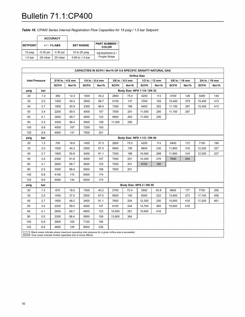
Table 16. CP400 Series Internal Registration Flow Capacities for 15 psig / 1.0 bar Setpoint
ACCuRACy
SETPOINT + / - 1% ABS SET RANGE PART NuMBER / COLOR
15 psig -0.30 psi 0.30 psi 10 to 20 psig GE30200X012 / Purple Stripe 1.0 bar -20 mbar 20 mbar 0.69 to 1.4 bar
CAPACITIES IN SCFH / Nm3/h OF 0.6 SPECIFIC GRAVITy NATuRAL GAS
Inlet PressureOrifice Size
3/16 In. / 4.8 mm 1/4 In. / 6.4 mm 3/8 In. / 9.5 mm 1/2 In. / 13 mm 5/8 In. / 16 mm 3/4 In. / 19 mmSCFH Nm3/h SCFH Nm3/h SCFH Nm3/h SCFH Nm3/h SCFH Nm3/h SCFH Nm3/h
psig bar Body Size: NPS 1-1/4 / DN 32
20 1.3 460 12.3 1500 40.2 2800 75.0 4200 113 4700 126 5400 145
30 2.0 1500 40.2 2600 69.7 5100 137 7200 193 10,400 279 15,400 413
40 2.7 1900 50.9 3300 88.4 7300 196 9400 252 11,100 297 15,400 413
50 3.4 2200 59.0 4000 107 7500 201 11,000 295 11,100 297
60 4.1 2600 69.7 4600 123 9800 263 11,000 295
80 5.5 3300 88.4 5900 158 11,000 295
100 6.8 4000 107 7200 193
125 8.6 4900 131 7500 201
psig bar Body Size: NPS 1-1/2 / DN 40
20 1.3 700 18.8 1400 37.5 2800 75.0 4200 113 6400 172 7100 190
30 2.0 1500 40.2 2500 67.0 5800 155 8600 230 11,800 316 12,200 327
40 2.7 1900 50.9 3400 91.1 7300 196 10,000 268 11,800 316 12,200 327
50 3.4 2300 61.6 4000 107 7500 201 10,300 276 7600 204
60 4.1 2600 69.7 4600 123 7500 201 6700 180
80 5.5 3300 88.4 5900 158 7500 201
100 6.8 4100 110 6500 174
125 8.6 5000 134 6500 174
psig bar Body Size: NPS 2 / DN 50
20 1.3 670 18.0 1500 40.2 2700 72.4 3500 93.8 6600 177 7700 206
30 2.0 1400 37.5 2500 67.0 5600 150 8300 222 13,900 373 17,100 458
40 2.7 1800 48.2 3400 91.1 7600 204 12,300 330 15,600 418 17,200 461
50 3.4 2200 59.0 4000 107 9100 244 14,700 394 15,600 418
60 4.1 2600 69.7 4600 123 10,500 281 15,600 418
80 5.5 3300 88.4 5900 158 13,600 364
100 6.8 3900 105 7100 190
125 8.6 4800 129 8900 239
Blank areas indicate where maximum operating inlet pressure for a given orifice size is exceeded. Gray areas indicate limited capacities due to boost effects.
Bulletin 71.1:CP400
17
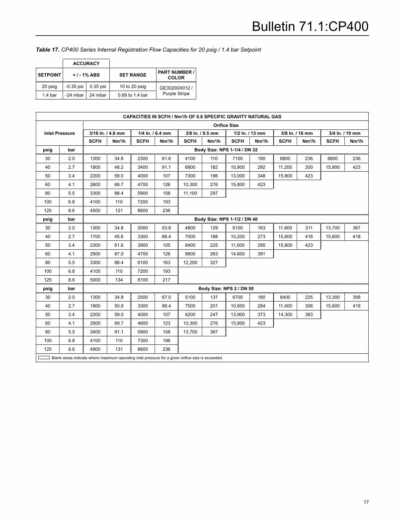
Table 17. CP400 Series Internal Registration Flow Capacities for 20 psig / 1.4 bar Setpoint
ACCuRACy
SETPOINT + / - 1% ABS SET RANGE PART NuMBER / COLOR
20 psig -0.35 psi 0.35 psi 10 to 20 psig GE30200X012 / Purple Stripe 1.4 bar -24 mbar 24 mbar 0.69 to 1.4 bar
CAPACITIES IN SCFH / Nm3/h OF 0.6 SPECIFIC GRAVITy NATuRAL GAS
Inlet PressureOrifice Size
3/16 In. / 4.8 mm 1/4 In. / 6.4 mm 3/8 In. / 9.5 mm 1/2 In. / 13 mm 5/8 In. / 16 mm 3/4 In. / 19 mmSCFH Nm3/h SCFH Nm3/h SCFH Nm3/h SCFH Nm3/h SCFH Nm3/h SCFH Nm3/h
psig bar Body Size: NPS 1-1/4 / DN 32
30 2.0 1300 34.8 2300 61.6 4100 110 7100 190 8800 236 8800 236
40 2.7 1800 48.2 3400 91.1 6800 182 10,900 292 11,200 300 15,800 423
50 3.4 2200 59.0 4000 107 7300 196 13,000 348 15,800 423
60 4.1 2600 69.7 4700 126 10,300 276 15,800 423
80 5.5 3300 88.4 5900 158 11,100 297
100 6.8 4100 110 7200 193
125 8.6 4500 121 8800 236
psig bar Body Size: NPS 1-1/2 / DN 40
30 2.0 1300 34.8 2000 53.6 4800 129 6100 163 11,600 311 13,700 367
40 2.7 1700 45.6 3300 88.4 7000 188 10,200 273 15,600 418 15,600 418
50 3.4 2300 61.6 3900 105 8400 225 11,000 295 15,800 423
60 4.1 2500 67.0 4700 126 9800 263 14,600 391
80 5.5 3300 88.4 6100 163 12,200 327
100 6.8 4100 110 7200 193
125 8.6 5000 134 8100 217
psig bar Body Size: NPS 2 / DN 50
30 2.0 1300 34.8 2500 67.0 5100 137 6700 180 8400 225 13,300 356
40 2.7 1900 50.9 3300 88.4 7500 201 10,600 284 11,400 306 15,600 418
50 3.4 2200 59.0 4000 107 9200 247 13,900 373 14,300 383
60 4.1 2600 69.7 4600 123 10,300 276 15,800 423
80 5.5 3400 91.1 5900 158 13,700 367
100 6.8 4100 110 7300 196
125 8.6 4900 131 8800 236
Blank areas indicate where maximum operating inlet pressure for a given orifice size is exceeded.

Bulletin 71.1:CP400
18
Table 18. Types CP403 and CP404 Internal Registration Flow Capacities for 2 psig / 0.14 bar Setpoint
Table 19. Types CP403 and CP404 Internal Registration Flow Capacities for 5 psig / 0.34 bar Setpoint
ACCuRACy
SETPOINT + / - 1% ABS SET RANGE PART NuMBER / COLOR
2 psig -0.17 psi 0.17 psi 1 to 2 psig GE30199X012 / Yellow Stripe0.14 bar -12 mbar 12 mbar 0.07 to 0.14 bar
ACCuRACy
SETPOINT + / - 1% ABS SET RANGE PART NuMBER / COLOR
5 psig -0.2 psi 0.2 psi 2 to 5 psig GE27213X012 / Orange Stripe0.34 bar -14 mbar 14 mbar 0.14 to 0.34 bar
CAPACITIES IN SCFH / Nm3/h OF 0.6 SPECIFIC GRAVITy NATuRAL GAS
Inlet Pressure
Orifice Size
3/16 In. / 4.8 mm 1/4 In. / 6.4 mm 3/8 In. / 9.5 mm 1/2 In. / 13 mm 5/8 In. / 16 mm 3/4 In. / 19 mm
SCFH Nm3/h SCFH Nm3/h SCFH Nm3/h SCFH Nm3/h SCFH Nm3/h SCFH Nm3/hpsig bar Body Sizes: NPS 1-1/4, 1-1/2 and 2 / DN 32, 40 and 50
3 0.21 240 6.43 450 12.1 840 22.5 880 23.6 1400 37.5 1300 34.8
5 0.34 450 12.1 740 19.8 1400 37.5 2500 67.0 2500 67.0 3200 85.810 0.69 810 21.7 1300 34.8 3000 80.4 4400 118 5600 150 6500 17415 1.0 980 26.3 1800 48.2 4000 107 6000 161 8200 220 9800 26320 1.4 1200 32.2 2100 56.3 4700 126 7500 201 8200 220 9800 26330 2.1 1500 40.2 2700 72.4 6300 169 7500 201 5100 137 5600 15040 2.8 1900 50.9 3400 91.1 7900 212 4900 131 4400 118 4700 12650 3.4 2200 59.0 4200 113 7900 212 4400 118 4000 10760 4.1 2600 69.7 4700 126 4700 126 4400 11880 5.5 3300 88.4 4700 126 4700 126100 6.9 4000 107 5100 137125 8.6 4900 131 5100 137
Blank areas indicate where maximum operating inlet pressure for a given orifice size is exceeded. Gray areas indicate limited capacities due to boost effects.
CAPACITIES IN SCFH / Nm3/h OF 0.6 SPECIFIC GRAVITy NATuRAL GAS
Inlet Pressure
Orifice Size
3/16 In. / 4.8 mm 1/4 In. / 6.4 mm 3/8 In. / 9.5 mm 1/2 In. / 13 mm 5/8 In. / 16 mm 3/4 In. / 19 mm
SCFH Nm3/h SCFH Nm3/h SCFH Nm3/h SCFH Nm3/h SCFH Nm3/h SCFH Nm3/hpsig bar Body Sizes: NPS 1-1/4, 1-1/2 and 2 / DN 32, 40 and 5010 0.69 630 16.9 1000 26.8 1600 42.9 2700 72.4 3500 93.8 3700 99.215 1.0 910 24.4 1400 37.5 3000 80.4 4400 118 5400 145 7400 19820 1.4 1100 29.5 2000 53.6 4000 107 6000 161 6800 182 7400 19830 2.1 1500 40.2 2700 72.4 6000 161 6000 161 6800 182 7400 19840 2.8 1900 50.9 3300 88.4 6000 161 5200 139 6800 182 6300 16950 3.4 2200 59.0 4000 107 6000 161 4400 118 7200 19360 4.1 2600 69.7 4700 126 5100 137 4400 11880 5.5 3300 88.4 6000 161 3700 99.2100 6.9 4000 107 6700 180125 8.6 4500 121 8400 225
Blank areas indicate where maximum operating inlet pressure for a given orifice size is exceeded. Gray areas indicate limited capacities due to boost effects.
Bulletin 71.1:CP400
19
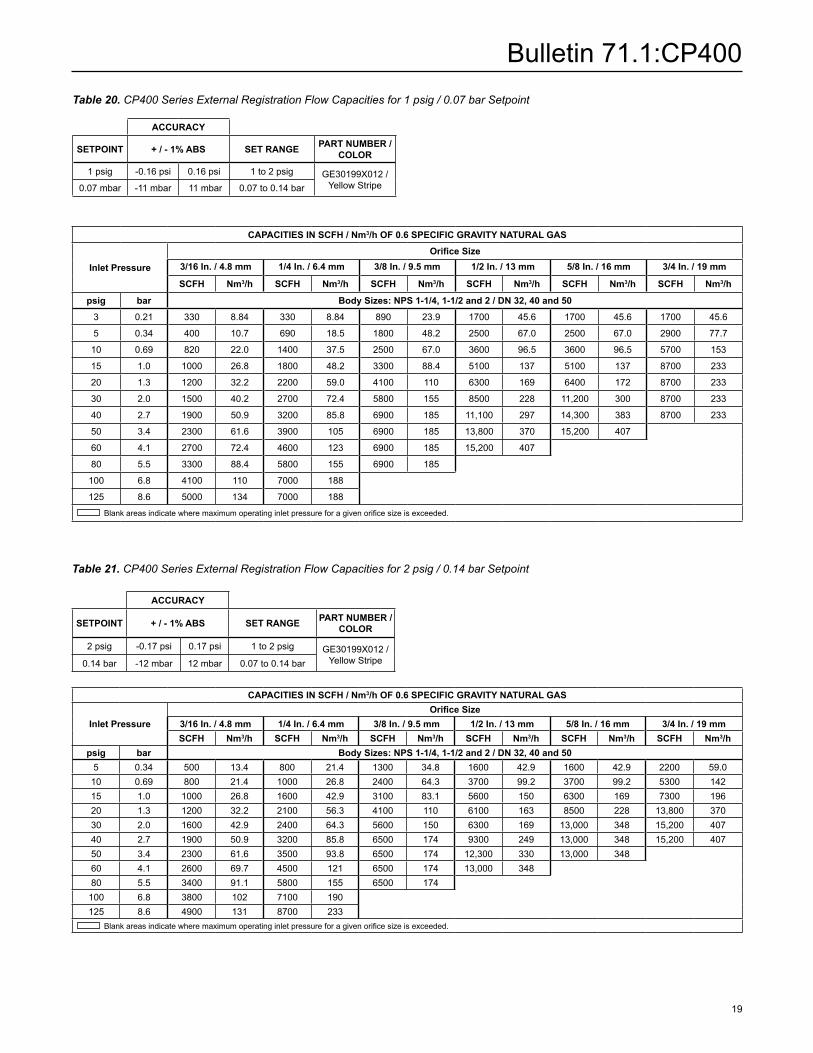
Table 20. CP400 Series External Registration Flow Capacities for 1 psig / 0.07 bar Setpoint
ACCuRACy
SETPOINT + / - 1% ABS SET RANGE PART NuMBER / COLOR
1 psig -0.16 psi 0.16 psi 1 to 2 psig GE30199X012 / Yellow Stripe 0.07 mbar -11 mbar 11 mbar 0.07 to 0.14 bar
Table 21. CP400 Series External Registration Flow Capacities for 2 psig / 0.14 bar Setpoint
ACCuRACy
SETPOINT + / - 1% ABS SET RANGE PART NuMBER / COLOR
2 psig -0.17 psi 0.17 psi 1 to 2 psig GE30199X012 / Yellow Stripe0.14 bar -12 mbar 12 mbar 0.07 to 0.14 bar
CAPACITIES IN SCFH / Nm3/h OF 0.6 SPECIFIC GRAVITy NATuRAL GAS
Inlet Pressure
Orifice Size3/16 In. / 4.8 mm 1/4 In. / 6.4 mm 3/8 In. / 9.5 mm 1/2 In. / 13 mm 5/8 In. / 16 mm 3/4 In. / 19 mm
SCFH Nm3/h SCFH Nm3/h SCFH Nm3/h SCFH Nm3/h SCFH Nm3/h SCFH Nm3/h
psig bar Body Sizes: NPS 1-1/4, 1-1/2 and 2 / DN 32, 40 and 50
3 0.21 330 8.84 330 8.84 890 23.9 1700 45.6 1700 45.6 1700 45.6
5 0.34 400 10.7 690 18.5 1800 48.2 2500 67.0 2500 67.0 2900 77.7
10 0.69 820 22.0 1400 37.5 2500 67.0 3600 96.5 3600 96.5 5700 153
15 1.0 1000 26.8 1800 48.2 3300 88.4 5100 137 5100 137 8700 233
20 1.3 1200 32.2 2200 59.0 4100 110 6300 169 6400 172 8700 233
30 2.0 1500 40.2 2700 72.4 5800 155 8500 228 11,200 300 8700 233
40 2.7 1900 50.9 3200 85.8 6900 185 11,100 297 14,300 383 8700 233
50 3.4 2300 61.6 3900 105 6900 185 13,800 370 15,200 407
60 4.1 2700 72.4 4600 123 6900 185 15,200 407
80 5.5 3300 88.4 5800 155 6900 185
100 6.8 4100 110 7000 188
125 8.6 5000 134 7000 188
Blank areas indicate where maximum operating inlet pressure for a given orifice size is exceeded.
CAPACITIES IN SCFH / Nm3/h OF 0.6 SPECIFIC GRAVITy NATuRAL GAS
Inlet PressureOrifice Size
3/16 In. / 4.8 mm 1/4 In. / 6.4 mm 3/8 In. / 9.5 mm 1/2 In. / 13 mm 5/8 In. / 16 mm 3/4 In. / 19 mmSCFH Nm3/h SCFH Nm3/h SCFH Nm3/h SCFH Nm3/h SCFH Nm3/h SCFH Nm3/h
psig bar Body Sizes: NPS 1-1/4, 1-1/2 and 2 / DN 32, 40 and 505 0.34 500 13.4 800 21.4 1300 34.8 1600 42.9 1600 42.9 2200 59.010 0.69 800 21.4 1000 26.8 2400 64.3 3700 99.2 3700 99.2 5300 14215 1.0 1000 26.8 1600 42.9 3100 83.1 5600 150 6300 169 7300 19620 1.3 1200 32.2 2100 56.3 4100 110 6100 163 8500 228 13,800 37030 2.0 1600 42.9 2400 64.3 5600 150 6300 169 13,000 348 15,200 40740 2.7 1900 50.9 3200 85.8 6500 174 9300 249 13,000 348 15,200 40750 3.4 2300 61.6 3500 93.8 6500 174 12,300 330 13,000 34860 4.1 2600 69.7 4500 121 6500 174 13,000 34880 5.5 3400 91.1 5800 155 6500 174100 6.8 3800 102 7100 190125 8.6 4900 131 8700 233
Blank areas indicate where maximum operating inlet pressure for a given orifice size is exceeded.

Bulletin 71.1:CP400
20
Table 22. CP400 Series External Registration Flow Capacities for 5 psig / 0.34 bar Setpoint
ACCuRACy
SETPOINT + / - 1% ABS SET RANGE PART NuMBER / COLOR
5 psig -0.2 psi 0.2 psi 2 to 5 psig GE27213X012 / Orange Stripe 0.34 bar -14 mbar 14 mbar 0.14 to 0.34 bar
Table 23. CP400 Series External Registration Flow Capacities for 10 psig / 0.69 bar Setpoint
ACCuRACy
SETPOINT + / - 1% ABS SET RANGE PART NuMBER / COLOR
10 psig -0.25 psi 0.25 psi 5 to 10 psig GE39890X012 / Black Stripe0.69 bar -17 mbar 17 mbar 0.34 to 0.69 bar
CAPACITIES IN SCFH / Nm3/h OF 0.6 SPECIFIC GRAVITy NATuRAL GAS
Inlet PressureOrifice Size
3/16 In. / 4.8 mm 1/4 In. / 6.4 mm 3/8 In. / 9.5 mm 1/2 In. / 13 mm 5/8 In. / 16 mm 3/4 In. / 19 mmSCFH Nm3/h SCFH Nm3/h SCFH Nm3/h SCFH Nm3/h SCFH Nm3/h SCFH Nm3/h
psig bar Body Sizes: NPS 1-1/4, 1-1/2 and 2 / DN 32, 40 and 50
10 0.69 520 13.9 980 26.3 1300 34.8 2200 59.0 3300 88.4 3300 88.4
15 1.0 770 20.6 1500 40.2 2900 77.7 4400 118 6600 177 6800 182
20 1.3 1100 29.5 2000 53.6 3800 102 6000 161 11,700 314 12,800 343
30 2.0 1300 34.8 2400 64.3 5300 142 8400 225 12,800 343 13,900 373
40 2.7 1700 45.6 3200 85.8 6500 174 10,800 289 17,200 461 17,200 461
50 3.4 1900 50.9 3800 102 9000 241 13,100 351 17,200 461
60 4.1 2200 59.0 4400 118 9500 255 14,500 389
80 5.5 3100 83.1 5900 158 13,300 356
100 6.8 3900 105 7000 188
125 8.6 4800 129 8700 233
Blank areas indicate where maximum operating inlet pressure for a given orifice size is exceeded.
CAPACITIES IN SCFH / Nm3/h OF 0.6 SPECIFIC GRAVITy NATuRAL GAS
Inlet PressureOrifice Size
3/16 In. / 4.8 mm 1/4 In. / 6.4 mm 3/8 In. / 9.5 mm 1/2 In. / 13 mm 5/8 In. / 16 mm 3/4 In. / 19 mmSCFH Nm3/h SCFH Nm3/h SCFH Nm3/h SCFH Nm3/h SCFH Nm3/h SCFH Nm3/h
psig bar Body Sizes: NPS 1-1/4, 1-1/2 and 2 / DN 32, 40 and 50
15 1.0 650 17.4 1300 34.8 2000 53.6 3100 83.1 3800 102 6300 169
20 1.3 990 26.5 1700 45.6 2700 72.4 6200 166 9800 263 10,300 276
30 2.0 1400 37.5 2400 64.3 5800 155 9500 255 14,500 389 15,800 423
40 2.7 1700 45.6 3100 83.1 6400 172 10,000 268 15,800 423 17,200 461
50 3.4 2000 53.6 3900 105 8700 233 12,300 330 16,700 448
60 4.1 2500 67.0 4500 121 9200 247 13,300 356
80 5.5 3100 83.1 5800 155 10,300 276
100 6.8 3500 93.8 7000 188
125 8.6 4400 118 8500 228
Blank areas indicate where maximum operating inlet pressure for a given orifice size is exceeded.

Bulletin 71.1:CP400
21
Table 24. CP400 Series External Registration Flow Capacities for 15 psig / 1.0 bar Setpoint
ACCuRACy
SETPOINT + / - 1% ABS SET RANGE PART NuMBER / COLOR
15 psig -0.30 psi 0.30 psi 10 to 20 psig GE30200X012 / Purple Stripe1.0 bar -20 mbar 20 mbar 0.69 to 1.4 bar
Table 25. CP400 Series External Registration Flow Capacities for 20 psig / 1.4 bar Setpoint
ACCuRACy
SETPOINT + / - 1% ABS SET RANGE PART NuMBER / COLOR
20 psig -0.35 psi 0.35 psi 10 to 20 psig GE30200X012 / Purple Stripe 1.4 bar -24 mbar 24 mbar 0.69 to 1.4 bar
CAPACITIES IN SCFH / Nm3/h OF 0.6 SPECIFIC GRAVITy NATuRAL GAS
Inlet PressureOrifice Size
3/16 In. / 4.8 mm 1/4 In. / 6.4 mm 3/8 In. / 9.5 mm 1/2 In. / 13 mm 5/8 In. / 16 mm 3/4 In. / 19 mmSCFH Nm3/h SCFH Nm3/h SCFH Nm3/h SCFH Nm3/h SCFH Nm3/h SCFH Nm3/h
psig bar Body Sizes: NPS 1-1/4, 1-1/2 and 2 / DN 32, 40 and 50
20 1.3 680 18.2 1300 34.8 2500 67.0 2800 75.0 4000 107 8500 228
30 2.0 1300 34.8 2200 59.0 5300 142 6300 169 8500 228 15,000 402
40 2.7 1500 40.2 3300 88.4 6100 163 11,800 316 14,300 383 17,600 472
50 3.4 2200 59.0 3600 96.5 7600 204 12,800 343 16,700 448
60 4.1 2400 64.3 4500 121 10,500 281 14,400 386
80 5.5 3000 80.4 5800 155 11,700 314
100 6.8 3600 96.5 6700 180
125 8.6 4300 115 8500 228
Blank areas indicate where maximum operating inlet pressure for a given orifice size is exceeded.
CAPACITIES IN SCFH / Nm3/h OF 0.6 SPECIFIC GRAVITy NATuRAL GAS
Inlet PressureOrifice Size
3/16 In. / 4.8 mm 1/4 In. / 6.4 mm 3/8 In. / 9.5 mm 1/2 In. / 13 mm 5/8 In. / 16 mm 3/4 In. / 19 mmSCFH Nm3/h SCFH Nm3/h SCFH Nm3/h SCFH Nm3/h SCFH Nm3/h SCFH Nm3/h
psig bar Body Sizes: NPS 1-1/4, 1-1/2 and 2 / DN 32, 40 and 50
30 2.0 960 25.7 2500 67.0 3400 91.1 6600 177 11,800 316 14,200 381
40 2.7 1400 37.5 2900 77.7 5500 147 9500 255 12,800 343 17,600 472
50 3.4 1900 50.9 3700 99.2 7500 201 13,600 364 14,400 386
60 4.1 2600 69.7 4000 107 8600 230 13,600 364
80 5.5 3000 80.4 5800 155 11,700 314
100 6.8 3900 105 6500 174
125 8.6 4900 131 8200 220
Blank areas indicate where maximum operating inlet pressure for a given orifice size is exceeded.

Bulletin 71.1:CP400
22
Table 26. Types CP403 and CP404 External Registration Flow Capacities for 2 psig / 0.14 bar Setpoint
Table 27. Types CP403 and CP404 External Registration Flow Capacities for 5 psig / 0.34 bar Setpoint
ACCuRACy
SETPOINT + / - 1% ABS SET RANGE PART NuMBER / COLOR
2 psig -0.17 psi 0.17 psi 1 to 2 psig GE30199X012 / Yellow Stripe0.14 bar -12 mbar 12 mbar 0.07 to 0.14 bar
ACCuRACy
SETPOINT + / - 1% ABS SET RANGE PART NuMBER / COLOR
5 psig -0.2 psi 0.2 psi 2 to 5 psig GE27213X012 / Orange Stripe0.34 bar -14 mbar 14 mbar 0.14 to 0.34 bar
CAPACITIES IN SCFH / Nm3/h OF 0.6 SPECIFIC GRAVITy NATuRAL GAS
Inlet Pressure
Orifice Size
3/16 In. / 4.8 mm 1/4 In. / 6.4 mm 3/8 In. / 9.5 mm 1/2 In. / 13 mm 5/8 In. / 16 mm 3/4 In. / 19 mm
SCFH Nm3/h SCFH Nm3/h SCFH Nm3/h SCFH Nm3/h SCFH Nm3/h SCFH Nm3/hpsig bar Body Sizes: NPS 1-1/4, 1-1/2 and 2 / DN 32, 40 and 50
3 0.20 280 7.50 380 10.2 740 19.8 1200 32.2 1400 37.5 1400 37.55 0.34 450 12.1 770 20.6 1400 37.5 1800 48.2 2200 59.0 2800 75.010 0.69 740 19.8 1300 34.8 2400 64.3 3300 88.4 3700 99.2 5400 14515 1.0 1000 26.8 1600 42.9 3000 80.4 4700 126 6800 182 7900 21220 1.4 1100 29.5 2100 56.3 4200 113 6100 163 9300 249 11,400 30630 2.1 1500 40.2 2600 69.7 6000 161 9300 249 13,700 367 16,900 45340 2.8 1900 50.9 3400 91.1 7400 198 11,800 316 18,700 501 21,000 56350 3.4 2200 59.0 4000 107 9000 241 15,500 415 23,300 62460 4.1 2600 69.7 4700 126 10,700 287 17,300 46480 5.5 3300 88.4 6000 161 13,700 367100 6.9 4000 107 7400 198125 8.6 4900 131 9000 241
Blank areas indicate where maximum operating inlet pressure for a given orifice size is exceeded.
CAPACITIES IN SCFH / Nm3/h OF 0.6 SPECIFIC GRAVITy NATuRAL GAS
Inlet Pressure
Orifice Size
3/16 In. / 4.8 mm 1/4 In. / 6.4 mm 3/8 In. / 9.5 mm 1/2 In. / 13 mm 5/8 In. / 16 mm 3/4 In. / 19 mm
SCFH Nm3/h SCFH Nm3/h SCFH Nm3/h SCFH Nm3/h SCFH Nm3/h SCFH Nm3/hpsig bar Body Sizes: NPS 1-1/4, 1-1/2 and 2 / DN 32, 40 and 5010 0.69 520 13.9 1000 26.8 1500 40.2 2400 64.3 2800 75.0 3100 83.115 1.0 810 21.7 1300 34.8 2700 72.4 3700 99.2 4500 121 5600 15020 1.4 1000 26.8 1800 48.2 3200 85.8 5200 139 6300 169 8100 21730 2.1 1400 37.5 2700 72.4 4900 131 7700 206 10,500 281 13,200 35440 2.8 1800 48.2 3200 85.8 6800 182 10,200 273 15,300 410 18,500 49650 3.4 2100 56.3 4000 107 9100 244 13,000 348 19,900 53360 4.1 2500 67.0 4500 121 10,000 268 16,700 44880 5.5 3200 85.8 5800 155 13,000 348100 6.9 4000 107 7000 188
125 8.6 4700 126 8200 220 Blank areas indicate where maximum operating inlet pressure for a given orifice size is exceeded.

Bulletin 71.1:CP400
23
Table 29. CP400 Series Internal Registration Flow Capacities for 2 psig / 0.14 bar Setpoint with 1% Pressure Factor Accuracy
ACCuRACy
SETPOINT + / - 1% ABS SET RANGE PART NuMBER / COLOR
2 psig -0.17 psi 0.17 psi 1 to 2 psig GE30199X012 / Yellow Stripe0.14 bar -12 mbar 12 mbar 0.07 to 0.14 bar
CAPACITIES IN SCFH / Nm3/h OF 0.6 SPECIFIC GRAVITy NATuRAL GAS
Inlet PressureOrifice Size
3/16 In. / 4.8 mm 1/4 In. / 6.4 mm 3/8 In. / 9.5 mm 1/2 In. / 13 mm 3/4 In. / 19 mmSCFH Nm3/h SCFH Nm3/h SCFH Nm3/h SCFH Nm3/h SCFH Nm3/h
psig bar Body Size: NPS 1-1/4 / DN 3210 0.69 750 20.1 1300 34.8 2200 59.0 3600 96.5 6500 17415 1.0 990 26.5 1800 48.2 3500 93.8 5000 134 7200 19320 1.4 1100 29.5 2100 56.3 4300 115 5000 134 7200 19325 1.7 1300 34.8 2400 64.3 5100 137 5000 134 7200 19330 2.1 1400 37.5 2700 72.4 5800 155 5000 134 3900 10540 2.8 1900 50.9 3300 88.4 6000 161 4700 126 3100 83.150 3.4 2200 59.0 3900 105 4200 113 4700 126 60 4.1 2500 67.0 4200 113 4200 113 4700 12680 5.5 3200 85.8 4200 113 4200 113
psig bar Body Size: NPS 1-1/2 / DN 4010 0.69 690 18.5 1200 32.2 2500 67.0 3700 99.2 6400 17215 1.0 960 25.7 1500 40.2 3500 93.8 5600 150 6400 17220 1.4 1100 29.5 2100 56.3 4400 118 5600 150 6400 17225 1.7 1300 34.8 2400 64.3 5300 142 5600 150 4000 10730 2.1 1400 37.5 2600 69.7 5600 150 5600 150 3400 91.140 2.8 1800 48.2 3200 85.8 5600 150 3400 91.1 3200 85.850 3.4 2100 56.3 3900 105 5600 150 3200 85.8 60 4.1 2400 64.3 4700 126 5600 150 3200 85.880 5.5 3200 85.8 5900 158 6300 169 100 6.9 3800 102 psig bar Body Size: NPS 2 / DN 5010 0.69 620 16.6 1200 32.2 2600 69.7 3000 80.4 4800 12915 1.0 890 23.9 1800 48.2 3600 96.5 5700 153 5700 15320 1.4 1000 26.8 2100 56.3 4500 121 7100 190 7100 19025 1.7 1300 34.8 2400 64.3 5400 145 7100 190 6100 16330 2.1 1500 40.2 2700 72.4 6000 161 7100 190 5700 15340 2.8 1900 50.9 3300 88.4 6000 161 7100 190 4900 13150 3.4 2200 59.0 4000 107 6000 161 7100 190 60 4.1 2600 69.7 4600 123 6000 161 7100 19080 5.5 3300 88.4 5900 158 6000 161 Blank areas indicate where maximum operating inlet pressure for a given orifice size is exceeded. Gray areas indicate limited capacities due to boost effects.
BODy SIZE,
NPS / DN
SETPOINT
ORIFICE SIZE, In. / mm3/16 / 4.8 1/4 / 6.4 3/8 / 9.5 1/2 / 13 3/4 / 19Inlet Set
PressureInlet Set Pressure
Inlet Set Pressure
Inlet Set Pressure
Inlet Set Pressure
psig bar psig bar psig bar psig bar psig bar psig bar
1-1/4 / 32
2 0.14 60 4.1 60 4.1 40 2.8 25 1.7 10 0.695 0.34 40 2.8 60 4.1 25 1.7 25 1.7 15 1.07 0.48 80 5.5 40 2.8 50 3.4 25 1.7 25 1.710 0.69 80 5.5 80 5.5 25 1.7 25 1.7 20 1.415 1.0 60 4.1 40 2.8 25 1.7 25 1.7 25 1.720 1.4 60 4.1 40 2.8 40 2.8 30 2.1 25 1.7
1-1/2 / 40
2 0.14 80 5.5 60 4.1 25 1.7 25 1.7 10 0.695 0.34 60 4.1 60 4.1 25 1.7 25 1.7 15 1.07 0.48 60 4.1 60 4.1 25 1.7 25 1.7 25 1.710 0.69 80 5.5 60 4.1 60 4.1 25 1.7 20 1.415 1.0 60 4.1 40 2.8 25 1.7 25 1.7 25 1.720 1.4 60 4.1 40 2.8 40 2.8 30 2.1 30 2.1
2 / 50
2 0.14 60 4.1 60 4.1 30 2.1 25 1.7 20 1.45 0.34 60 4.1 50 3.4 25 1.7 25 1.7 20 1.47 0.48 80 5.5 60 4.1 25 1.7 25 1.7 25 1.710 0.69 60 4.1 40 2.8 25 1.7 25 1.7 20 1.415 1.0 60 4.1 60 4.1 25 1.7 25 1.7 30 2.120 1.4 60 4.1 40 2.8 30 2.1 30 2.1 25 1.7
Table 28. Type CP400 Inlet Set Pressure for Pressure Factor Measurement (PFM) Service
Bulletin 71.1:CP400
24
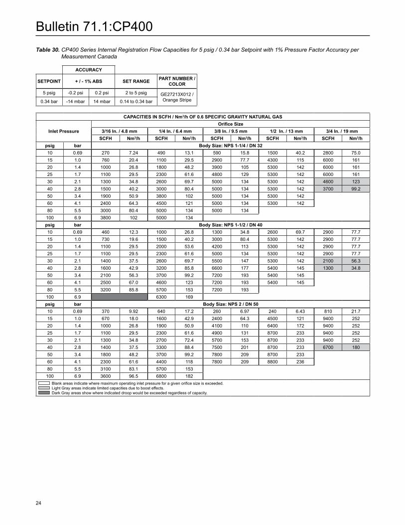
Table 30. CP400 Series Internal Registration Flow Capacities for 5 psig / 0.34 bar Setpoint with 1% Pressure Factor Accuracy per Measurement Canada
ACCuRACy
SETPOINT + / - 1% ABS SET RANGE PART NuMBER / COLOR
5 psig -0.2 psi 0.2 psi 2 to 5 psig GE27213X012 / Orange Stripe0.34 bar -14 mbar 14 mbar 0.14 to 0.34 bar
CAPACITIES IN SCFH / Nm3/h OF 0.6 SPECIFIC GRAVITy NATuRAL GAS
Inlet PressureOrifice Size
3/16 In. / 4.8 mm 1/4 In. / 6.4 mm 3/8 In. / 9.5 mm 1/2 In. / 13 mm 3/4 In. / 19 mmSCFH Nm3/h SCFH Nm3/h SCFH Nm3/h SCFH Nm3/h SCFH Nm3/h
psig bar Body Size: NPS 1-1/4 / DN 3210 0.69 270 7.24 490 13.1 590 15.8 1500 40.2 2800 75.015 1.0 760 20.4 1100 29.5 2900 77.7 4300 115 6000 16120 1.4 1000 26.8 1800 48.2 3900 105 5300 142 6000 16125 1.7 1100 29.5 2300 61.6 4800 129 5300 142 6000 16130 2.1 1300 34.8 2600 69.7 5000 134 5300 142 4600 12340 2.8 1500 40.2 3000 80.4 5000 134 5300 142 3700 99.250 3.4 1900 50.9 3800 102 5000 134 5300 142 60 4.1 2400 64.3 4500 121 5000 134 5300 14280 5.5 3000 80.4 5000 134 5000 134
100 6.9 3800 102 5000 134 psig bar Body Size: NPS 1-1/2 / DN 4010 0.69 460 12.3 1000 26.8 1300 34.8 2600 69.7 2900 77.715 1.0 730 19.6 1500 40.2 3000 80.4 5300 142 2900 77.720 1.4 1100 29.5 2000 53.6 4200 113 5300 142 2900 77.725 1.7 1100 29.5 2300 61.6 5000 134 5300 142 2900 77.730 2.1 1400 37.5 2600 69.7 5500 147 5300 142 2100 56.340 2.8 1600 42.9 3200 85.8 6600 177 5400 145 1300 34.850 3.4 2100 56.3 3700 99.2 7200 193 5400 145 60 4.1 2500 67.0 4600 123 7200 193 5400 14580 5.5 3200 85.8 5700 153 7200 193
100 6.9 6300 169 psig bar Body Size: NPS 2 / DN 5010 0.69 370 9.92 640 17.2 260 6.97 240 6.43 810 21.715 1.0 670 18.0 1600 42.9 2400 64.3 4500 121 9400 25220 1.4 1000 26.8 1900 50.9 4100 110 6400 172 9400 25225 1.7 1100 29.5 2300 61.6 4900 131 8700 233 9400 25230 2.1 1300 34.8 2700 72.4 5700 153 8700 233 9400 25240 2.8 1400 37.5 3300 88.4 7500 201 8700 233 6700 18050 3.4 1800 48.2 3700 99.2 7800 209 8700 233 60 4.1 2300 61.6 4400 118 7800 209 8800 23680 5.5 3100 83.1 5700 153 100 6.9 3600 96.5 6800 182
Blank areas indicate where maximum operating inlet pressure for a given orifice size is exceeded. Light Gray areas indicate limited capacities due to boost effects. Dark Gray areas show where indicated droop would be exceeded regardless of capacity.
Bulletin 71.1:CP400
25
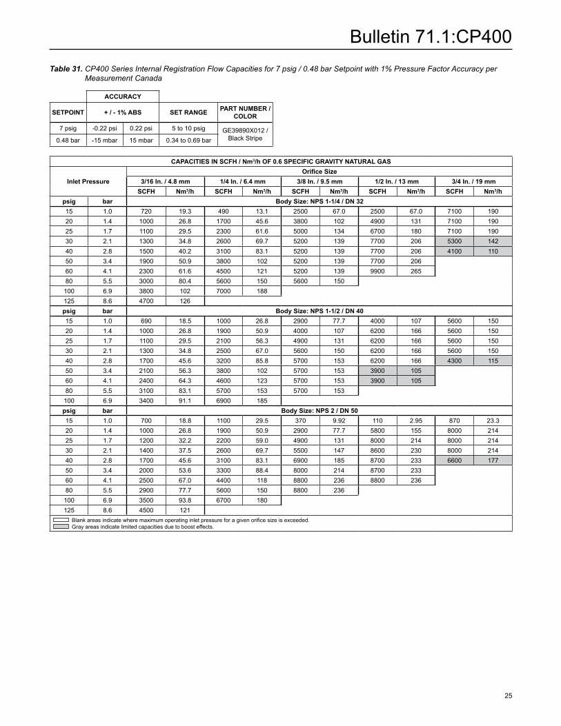
Table 31. CP400 Series Internal Registration Flow Capacities for 7 psig / 0.48 bar Setpoint with 1% Pressure Factor Accuracy per Measurement Canada
ACCuRACy
SETPOINT + / - 1% ABS SET RANGE PART NuMBER / COLOR
7 psig -0.22 psi 0.22 psi 5 to 10 psig GE39890X012 / Black Stripe0.48 bar -15 mbar 15 mbar 0.34 to 0.69 bar
CAPACITIES IN SCFH / Nm3/h OF 0.6 SPECIFIC GRAVITy NATuRAL GAS
Inlet PressureOrifice Size
3/16 In. / 4.8 mm 1/4 In. / 6.4 mm 3/8 In. / 9.5 mm 1/2 In. / 13 mm 3/4 In. / 19 mmSCFH Nm3/h SCFH Nm3/h SCFH Nm3/h SCFH Nm3/h SCFH Nm3/h
psig bar Body Size: NPS 1-1/4 / DN 3215 1.0 720 19.3 490 13.1 2500 67.0 2500 67.0 7100 19020 1.4 1000 26.8 1700 45.6 3800 102 4900 131 7100 19025 1.7 1100 29.5 2300 61.6 5000 134 6700 180 7100 19030 2.1 1300 34.8 2600 69.7 5200 139 7700 206 5300 14240 2.8 1500 40.2 3100 83.1 5200 139 7700 206 4100 11050 3.4 1900 50.9 3800 102 5200 139 7700 206 60 4.1 2300 61.6 4500 121 5200 139 9900 26580 5.5 3000 80.4 5600 150 5600 150
100 6.9 3800 102 7000 188 125 8.6 4700 126psig bar Body Size: NPS 1-1/2 / DN 4015 1.0 690 18.5 1000 26.8 2900 77.7 4000 107 5600 15020 1.4 1000 26.8 1900 50.9 4000 107 6200 166 5600 15025 1.7 1100 29.5 2100 56.3 4900 131 6200 166 5600 15030 2.1 1300 34.8 2500 67.0 5600 150 6200 166 5600 15040 2.8 1700 45.6 3200 85.8 5700 153 6200 166 4300 11550 3.4 2100 56.3 3800 102 5700 153 3900 105 60 4.1 2400 64.3 4600 123 5700 153 3900 10580 5.5 3100 83.1 5700 153 5700 153
100 6.9 3400 91.1 6900 185 psig bar Body Size: NPS 2 / DN 5015 1.0 700 18.8 1100 29.5 370 9.92 110 2.95 870 23.320 1.4 1000 26.8 1900 50.9 2900 77.7 5800 155 8000 21425 1.7 1200 32.2 2200 59.0 4900 131 8000 214 8000 21430 2.1 1400 37.5 2600 69.7 5500 147 8600 230 8000 21440 2.8 1700 45.6 3100 83.1 6900 185 8700 233 6600 17750 3.4 2000 53.6 3300 88.4 8000 214 8700 233 60 4.1 2500 67.0 4400 118 8800 236 8800 23680 5.5 2900 77.7 5600 150 8800 236
100 6.9 3500 93.8 6700 180 125 8.6 4500 121
Blank areas indicate where maximum operating inlet pressure for a given orifice size is exceeded. Gray areas indicate limited capacities due to boost effects.
Bulletin 71.1:CP400
26
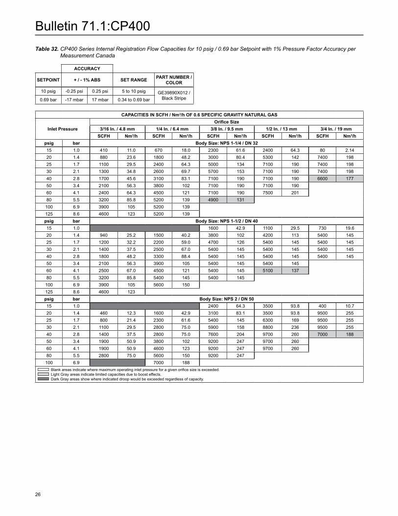
Table 32. CP400 Series Internal Registration Flow Capacities for 10 psig / 0.69 bar Setpoint with 1% Pressure Factor Accuracy per Measurement Canada
ACCuRACy
SETPOINT + / - 1% ABS SET RANGE PART NuMBER / COLOR
10 psig -0.25 psi 0.25 psi 5 to 10 psig GE39890X012 / Black Stripe0.69 bar -17 mbar 17 mbar 0.34 to 0.69 bar
CAPACITIES IN SCFH / Nm3/h OF 0.6 SPECIFIC GRAVITy NATuRAL GAS
Inlet PressureOrifice Size
3/16 In. / 4.8 mm 1/4 In. / 6.4 mm 3/8 In. / 9.5 mm 1/2 In. / 13 mm 3/4 In. / 19 mmSCFH Nm3/h SCFH Nm3/h SCFH Nm3/h SCFH Nm3/h SCFH Nm3/h
psig bar Body Size: NPS 1-1/4 / DN 3215 1.0 410 11.0 670 18.0 2300 61.6 2400 64.3 80 2.1420 1.4 880 23.6 1800 48.2 3000 80.4 5300 142 7400 19825 1.7 1100 29.5 2400 64.3 5000 134 7100 190 7400 19830 2.1 1300 34.8 2600 69.7 5700 153 7100 190 7400 19840 2.8 1700 45.6 3100 83.1 7100 190 7100 190 6600 17750 3.4 2100 56.3 3800 102 7100 190 7100 190 60 4.1 2400 64.3 4500 121 7100 190 7500 20180 5.5 3200 85.8 5200 139 4900 131
100 6.9 3900 105 5200 139 125 8.6 4600 123 5200 139 psig bar Body Size: NPS 1-1/2 / DN 4015 1.0 1600 42.9 1100 29.5 730 19.620 1.4 940 25.2 1500 40.2 3800 102 4200 113 5400 14525 1.7 1200 32.2 2200 59.0 4700 126 5400 145 5400 14530 2.1 1400 37.5 2500 67.0 5400 145 5400 145 5400 14540 2.8 1800 48.2 3300 88.4 5400 145 5400 145 5400 14550 3.4 2100 56.3 3900 105 5400 145 5400 145 60 4.1 2500 67.0 4500 121 5400 145 5100 13780 5.5 3200 85.8 5400 145 5400 145
100 6.9 3900 105 5600 150 125 8.6 4600 123 psig bar Body Size: NPS 2 / DN 5015 1.0 2400 64.3 3500 93.8 400 10.720 1.4 460 12.3 1600 42.9 3100 83.1 3500 93.8 9500 25525 1.7 800 21.4 2300 61.6 5400 145 6300 169 9500 25530 2.1 1100 29.5 2800 75.0 5900 158 8800 236 9500 25540 2.8 1400 37.5 2800 75.0 7600 204 9700 260 7000 18850 3.4 1900 50.9 3800 102 9200 247 9700 260 60 4.1 1900 50.9 4600 123 9200 247 9700 26080 5.5 2800 75.0 5600 150 9200 247
100 6.9 7000 188 Blank areas indicate where maximum operating inlet pressure for a given orifice size is exceeded. Light Gray areas indicate limited capacities due to boost effects. Dark Gray areas show where indicated droop would be exceeded regardless of capacity.
Bulletin 71.1:CP400
27
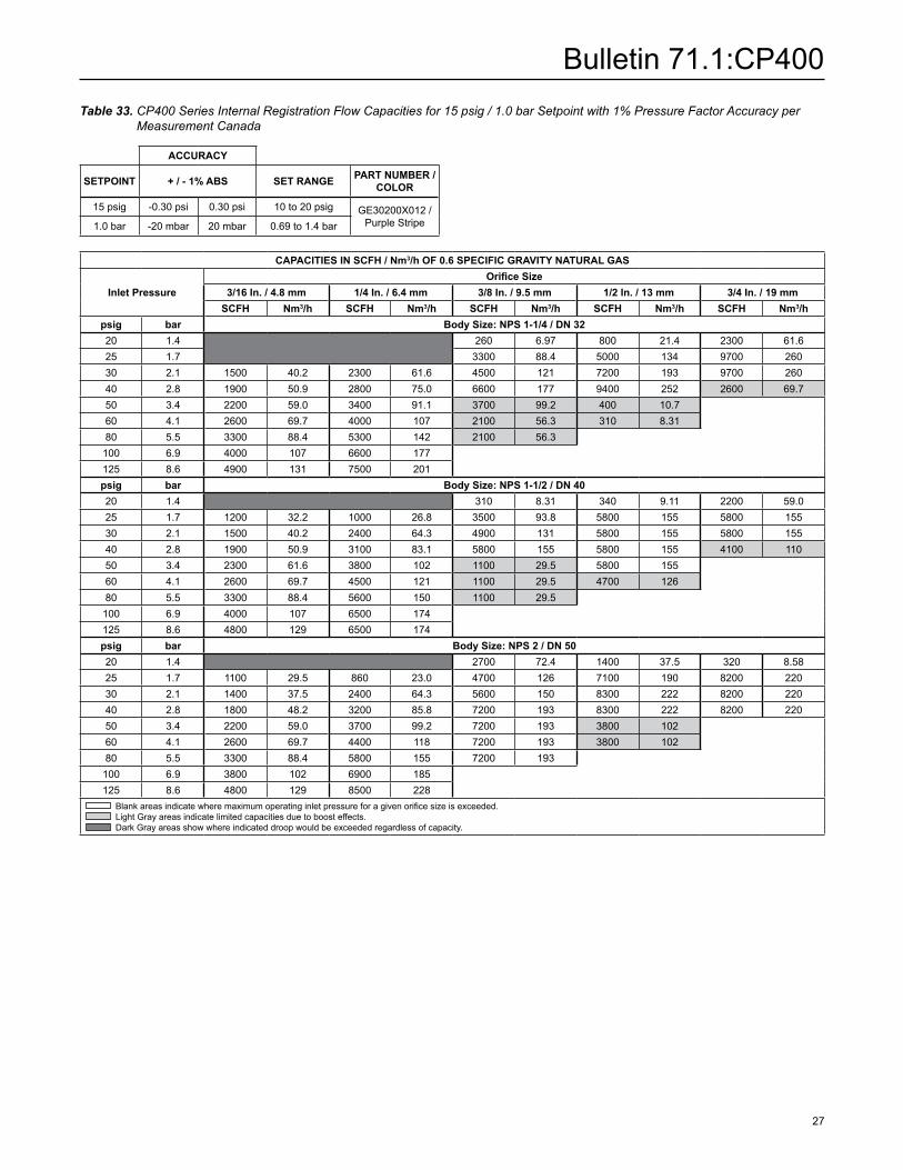
Table 33. CP400 Series Internal Registration Flow Capacities for 15 psig / 1.0 bar Setpoint with 1% Pressure Factor Accuracy per Measurement Canada
ACCuRACy
SETPOINT + / - 1% ABS SET RANGE PART NuMBER / COLOR
15 psig -0.30 psi 0.30 psi 10 to 20 psig GE30200X012 / Purple Stripe1.0 bar -20 mbar 20 mbar 0.69 to 1.4 bar
CAPACITIES IN SCFH / Nm3/h OF 0.6 SPECIFIC GRAVITy NATuRAL GAS
Inlet PressureOrifice Size
3/16 In. / 4.8 mm 1/4 In. / 6.4 mm 3/8 In. / 9.5 mm 1/2 In. / 13 mm 3/4 In. / 19 mmSCFH Nm3/h SCFH Nm3/h SCFH Nm3/h SCFH Nm3/h SCFH Nm3/h
psig bar Body Size: NPS 1-1/4 / DN 3220 1.4 260 6.97 800 21.4 2300 61.625 1.7 3300 88.4 5000 134 9700 26030 2.1 1500 40.2 2300 61.6 4500 121 7200 193 9700 26040 2.8 1900 50.9 2800 75.0 6600 177 9400 252 2600 69.750 3.4 2200 59.0 3400 91.1 3700 99.2 400 10.7 60 4.1 2600 69.7 4000 107 2100 56.3 310 8.3180 5.5 3300 88.4 5300 142 2100 56.3
100 6.9 4000 107 6600 177 125 8.6 4900 131 7500 201 psig bar Body Size: NPS 1-1/2 / DN 4020 1.4 310 8.31 340 9.11 2200 59.025 1.7 1200 32.2 1000 26.8 3500 93.8 5800 155 5800 15530 2.1 1500 40.2 2400 64.3 4900 131 5800 155 5800 15540 2.8 1900 50.9 3100 83.1 5800 155 5800 155 4100 11050 3.4 2300 61.6 3800 102 1100 29.5 5800 155 60 4.1 2600 69.7 4500 121 1100 29.5 4700 12680 5.5 3300 88.4 5600 150 1100 29.5
100 6.9 4000 107 6500 174 125 8.6 4800 129 6500 174 psig bar Body Size: NPS 2 / DN 5020 1.4 2700 72.4 1400 37.5 320 8.5825 1.7 1100 29.5 860 23.0 4700 126 7100 190 8200 22030 2.1 1400 37.5 2400 64.3 5600 150 8300 222 8200 22040 2.8 1800 48.2 3200 85.8 7200 193 8300 222 8200 22050 3.4 2200 59.0 3700 99.2 7200 193 3800 102 60 4.1 2600 69.7 4400 118 7200 193 3800 10280 5.5 3300 88.4 5800 155 7200 193
100 6.9 3800 102 6900 185 125 8.6 4800 129 8500 228
Blank areas indicate where maximum operating inlet pressure for a given orifice size is exceeded. Light Gray areas indicate limited capacities due to boost effects. Dark Gray areas show where indicated droop would be exceeded regardless of capacity.

Bulletin 71.1:CP400
28
Table 34. CP400 Series Internal Registration Flow Capacities for 20 psig / 1.4 bar Setpoint with 1% Pressure Factor Accuracy per Measurement Canada
ACCuRACy
SETPOINT + / - 1% ABS SET RANGE PART NuMBER / COLOR
20 psig -0.35 psi 0.35 psi 10 to 20 psig GE30200X012 / Purple Stripe1.4 bar -24 mbar 24 mbar 0.69 to 1.4 bar
CAPACITIES IN SCFH / Nm3/h OF 0.6 SPECIFIC GRAVITy NATuRAL GAS
Inlet PressureOrifice Size
3/16 In. / 4.8 mm 1/4 In. / 6.4 mm 3/8 In. / 9.5 mm 1/2 In. / 13 mm 3/4 In. / 19 mmSCFH Nm3/h SCFH Nm3/h SCFH Nm3/h SCFH Nm3/h SCFH Nm3/h
psig bar Body Size: NPS 1-1/4 / DN 3225 1.7 1500 40.2 3900 10530 2.1 1300 34.8 2300 61.6 5400 145 8800 23640 2.8 1800 48.2 3400 91.1 5700 153 5400 145 50 3.4 2200 59.0 4000 107 7300 196 4400 118 60 4.1 2600 69.7 4600 123 9900 265 3300 88.480 5.5 3200 85.8 5900 158 9900 265
100 6.9 4000 107 7200 193 psig bar Body Size: NPS 1-1/2 / DN 4025 1.7 1000 26.8 1600 42.9 540 14.5 1100 29.530 2.1 1000 26.8 2000 53.6 4200 113 5900 158 5900 15840 2.8 1700 45.6 3200 85.8 5500 147 5900 158 5900 15850 3.4 2200 59.0 3900 105 5500 147 5900 158 60 4.1 2400 64.3 4700 126 5500 147 6400 17280 5.5 3200 85.8 6000 161 5500 147
100 6.9 3800 102 7200 193 125 8.6 4600 123 8000 214 psig bar Body Size: NPS 2 / DN 5025 1.7 110 2.95 1100 29.5 1500 40.230 2.1 730 19.6 1700 45.6 4000 107 6400 172 9600 25740 2.8 1600 42.9 2900 77.7 6700 180 8900 239 9600 25750 3.4 2000 53.6 3800 102 8700 233 8900 239 60 4.1 2300 61.6 4200 113 8900 239 8900 23980 5.5 3200 85.8 5500 147 9900 265
100 6.9 3800 102 6900 185 125 8.6 4800 129 8300 222
Blank areas indicate where maximum operating inlet pressure for a given orifice size is exceeded. Light Gray areas indicate limited capacities due to boost effects. Dark Gray areas show where indicated droop would be exceeded regardless of capacity.
Bulletin 71.1:CP400
29
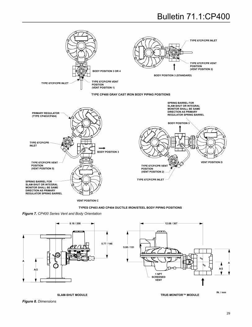
Figure 7. CP400 Series Vent and Body Orientation
SLAM-SHuT MODuLE TRuE-MONITOR™ MODuLE
Figure 8. Dimensions
IN. / mm
TYPE 67CP/CPR INLET
BODY POSITION 3
VENT POSITION C
BODY POSITION 3
BODY POSITION 3 (STANDARD)
VENT POSITION D
TYPE 67CP/CPR VENTPOSITION(VENT POSITION 1)
TYPE 67CP/CPR VENTPOSITION(VENT POSITION 2)
TYPE 67CP/CPR VENTPOSITION(VENT POSITION 5)
SPRING BARREL FORSLAM-SHUT OR INTEGRALMONITOR SHALL BE SAMEDIRECTION AS PRIMARYREGULATOR SPRING BARREL
SPRING BARREL FORSLAM-SHUT OR INTEGRALMONITOR SHALL BE SAMEDIRECTION AS PRIMARYREGULATOR SPRING BARRELPRIMARY REGULATOR
(TYPE CP403/CP404)
TYPE 67CP/CPRINLET
TYPE 67CP/CPR INLET
TYPE 67CP/CPR INLET
TYPE 67CP/CPR VENTPOSITION(VENT POSITION 2)
BODY POSITION 3 OR 4
TYPE CP400 GRAY CAST IRON BODY PIPING POSITIONS
TYPES CP403 AND CP404 DUCTILE IRON/STEEL BODY PIPING POSITIONS
A
A/2
A
A/2
8.18 / 208
1 NPT SCREENED
VENT
5.77 / 1465.95 / 151
12.08 / 307
A
A
A/2
A/2
A
A/2
A
A/2
13.7 / 347
9.22 / 234
6.57 / 167
2.13 / 54 1.79 / 45
10.6 / 269
13.1 / 332
11.10 / 282

Bulletin 71.1:CP400
30
Figure 8. Dimensions (continued)
Table 35. Dimensions
BODy SIZE
END CONNECTION STyLES, IN. / mm
A
NPT / Rp CL125 FF / CL150 FF / PN 16
1-1/44.49 / 114
- - - -
1-1/2 - - - -
1 3.94 / 100 - - - -
NPS 2 / DN 50 5 / 127 10 / 254
IN. / mm
GRAy CAST IRON FLANGED BODyDuCTILE IRON OR STEEL FLANGED BODy
GRAy CAST IRON THREADED BODyDuCTILE IRON OR STEEL THREADED BODy
A
A/2
A
A/2
8.18 / 208
1 NPT SCREENED
VENT
5.77 / 1465.95 / 151
12.08 / 307
A
A
A/2
A/2
A
A/2
A
A/2
13.7 / 347
9.22 / 234
6.57 / 167
2.13 / 54 1.79 / 45
10.6 / 269
13.1 / 332
11.10 / 282
A
A/2
A
A/2
8.18 / 208
1 NPT SCREENED
VENT
5.77 / 1465.95 / 151
12.08 / 307
A
A
A/2
A/2
A
A/2
A
A/2
13.7 / 347
9.22 / 234
6.57 / 167
2.13 / 54 1.79 / 45
10.6 / 269
13.1 / 332
11.10 / 282
Bulletin 71.1:CP400
31
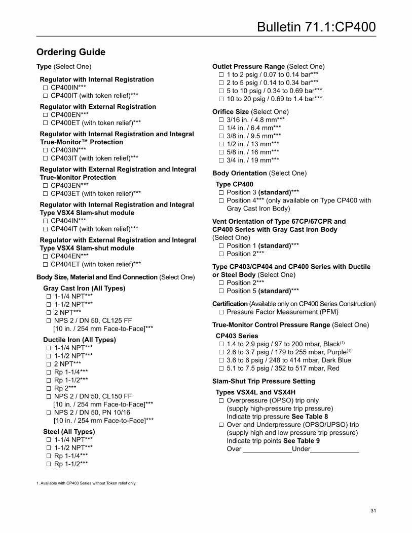
Ordering GuideType (Select One)
Regulator with Internal Registration CP400IN*** CP400IT (with token relief)*** Regulator with External Registration CP400EN*** CP400ET (with token relief)*** Regulator with Internal Registration and Integral True-Monitor™ Protection CP403IN*** CP403IT (with token relief)*** Regulator with External Registration and Integral True-Monitor Protection CP403EN*** CP403ET (with token relief)*** Regulator with Internal Registration and Integral Type VSX4 Slam-shut module CP404IN*** CP404IT (with token relief)*** Regulator with External Registration and Integral Type VSX4 Slam-shut module CP404EN*** CP404ET (with token relief)***
Body Size, Material and End Connection (Select One) Gray Cast Iron (All Types) 1-1/4 NPT*** 1-1/2 NPT*** 2 NPT*** NPS 2 / DN 50, CL125 FF [10 in. / 254 mm Face-to-Face]*** Ductile Iron (All Types) 1-1/4 NPT*** 1-1/2 NPT*** 2 NPT*** Rp 1-1/4*** Rp 1-1/2*** Rp 2*** NPS 2 / DN 50, CL150 FF [10 in. / 254 mm Face-to-Face]*** NPS 2 / DN 50, PN 10/16 [10 in. / 254 mm Face-to-Face]*** Steel (All Types) 1-1/4 NPT*** 1-1/2 NPT*** Rp 1-1/4*** Rp 1-1/2***
Outlet Pressure Range (Select One) 1 to 2 psig / 0.07 to 0.14 bar*** 2 to 5 psig / 0.14 to 0.34 bar*** 5 to 10 psig / 0.34 to 0.69 bar*** 10 to 20 psig / 0.69 to 1.4 bar***
Orifice Size (Select One) 3/16 in. / 4.8 mm*** 1/4 in. / 6.4 mm*** 3/8 in. / 9.5 mm*** 1/2 in. / 13 mm*** 5/8 in. / 16 mm*** 3/4 in. / 19 mm***
Body Orientation (Select One) Type CP400 Position 3 (standard)*** Position 4*** (only available on Type CP400 with
Gray Cast Iron Body)
Vent Orientation of Type 67CP/67CPR and CP400 Series with Gray Cast Iron Body (Select One) Position 1 (standard)*** Position 2***
Type CP403/CP404 and CP400 Series with Ductile or Steel Body (Select One) Position 2*** Position 5 (standard)***
Certification (Available only on CP400 Series Construction) Pressure Factor Measurement (PFM)
True-Monitor Control Pressure Range (Select One) CP403 Series 1.4 to 2.9 psig / 97 to 200 mbar, Black(1)
2.6 to 3.7 psig / 179 to 255 mbar, Purple(1)
3.6 to 6 psig / 248 to 414 mbar, Dark Blue 5.1 to 7.5 psig / 352 to 517 mbar, Red
Slam-Shut Trip Pressure Setting Types VSX4L and VSX4H Overpressure (OPSO) trip only
(supply high-pressure trip pressure) Indicate trip pressure See Table 8
Over and Underpressure (OPSO/UPSO) trip (supply high and low pressure trip pressure) Indicate trip points See Table 9 Over _____________Under_____________
1. Available with CP403 Series without Token relief only.

Bulletin 71.1:CP400
©Emerson Process Management Regulator Technologies, Inc., 2008, 2014; All Rights Reserved
Industrial Regulators
Emerson Process Management Regulator Technologies, Inc.
USA - HeadquartersMcKinney, Texas 75070 USATel: +1 800 558 5853Outside U.S. +1 972 548 3574
Asia-PacificShanghai 201206, ChinaTel: +86 21 2892 9000
EuropeBologna 40013, ItalyTel: +39 051 419 0611
Middle East and AfricaDubai, United Arab EmiratesTel: +971 4811 8100
Natural Gas Technologies
Emerson Process ManagementRegulator Technologies, Inc.
USA - HeadquartersMcKinney, Texas 75070 USATel: +1 800 558 5853Outside U.S. +1 972 548 3574
Asia-PacificSingapore 128461, SingaporeTel: +65 6770 8337
EuropeBologna 40013, ItalyTel: +39 051 419 0611Chartres 28008, FranceTel: +33 2 37 33 47 00
Middle East and AfricaDubai, United Arab EmiratesTel: +971 4811 8100
TESCOM
Emerson Process ManagementTescom Corporation
USA - HeadquartersElk River, Minnesota 55330-2445, USATels: +1 763 241 3238 +1 800 447 1250
EuropeSelmsdorf 23923, GermanyTel: +49 38823 31 287
Asia-PacificShanghai 201206, ChinaTel: +86 21 2892 9499
The Emerson logo is a trademark and service mark of Emerson Electric Co. All other marks are the property of their prospective owners. Fisher is a mark owned by Fisher Controls International LLC, a business of Emerson Process Management.
The contents of this publication are presented for informational purposes only, and while every effort has been made to ensure their accuracy, they are not to be construed as warranties or guarantees, express or implied, regarding the products or services described herein or their use or applicability. We reserve the right to modify or improve the designs or specifications of such products at any time without notice.
Emerson Process Management Regulator Technologies, Inc. does not assume responsibility for the selection, use or maintenance of any product. Responsibility for proper selection, use and maintenance of any Emerson Process Management Regulator Technologies, Inc. product remains solely with the purchaser.
For further information visit www.emersonprocess.com/regulators
The distinctive swirl pattern cast into every actuator casing uniquely identifies the regulator as part of the Fisher® brand Commercial Service Regulator family and assures you of the highest-quality engineering, performance, and support traditionally associated with Fisher®, Francel™ and Tartarini™ regulators. Visit www.fishercommercialservice.com to access interactive applications.
Regulators Quick Order Guide* * * Readily Available for Shipment* * Allow Additional Time for Shipment
* Special Order, Constructed from Non-Stocked Parts. Consultyour local Sales Office for Availability.
Availability of the product being ordered is determined by the component with the longest shipping time for the requested construction.
Specification WorksheetApplication:Specific UseLine SizeGas Type and Specific GravityGas TemperatureDoes the Application Require Overpressure Protection? Yes No If yes, which is preferred: Relief Valve Monitor Regulator Shutoff DeviceIs overpressure protection equipment selection assistance desired?
Pressure:Maximum Inlet Pressure (P1max)Minimum Inlet Pressure (P1min)Downstream Pressure Setting(s) (P2)Maximum Flow (Qmax)
Performance Required:Accuracy Requirements?Need for Fast Response?
Other Requirements:
Ordering Guide (continued)