separation of mixtures in mass transfer applications by ....pdf · separation of mixtures in mass...
TRANSCRIPT
International Journal of Scientific Engineering and Research (IJSER)www.ijser.in
ISSN (Online): 2347-3878 Volume 2 Issue 4, April 2014
Separation of Mixtures in Mass Transfer Applications by Fluidization
S. M. Subhani1, B. Srinivas2
1Department of Chemical Engineering, BVSREC, A.P., India
2Department of Chemical Engineering, JNT University, A.P., India
Abstract: Fluidization is an operation by which fine granular solids are transformed into a fluid-like state through contact with a fluid.This operation has proved very useful in the movement of granular solid particles through a series of steps in continuous fashion. When a liquid or gas is passed at very low velocity up through a bed of solid particles, the particle do not fluid velocity move, and the pressure drop is given by the Ergun equation. If the fluid velocity is steadily increased, the pressure drop and the drag on individual particle increase, and eventually the particles start to move and become suspended in the fluid. Separations of mixtures of solids are done by: 1. Screening 2. Froth Floatation 3. Jigging 4. WIlfley table 5. Cyclone Seperator etc….. In this work, fluidization is tried to separate solid mixtures of different sizes and densities. There is not enough literature on this separation topic up to now. An equation is formulated to calculate the separation amount based on dimensional analysis and experiments. The error is using this equation is 22%.This work is useful to separate large amount of solids, like in industries and in business houses economically.
Keywords: Fluidization of binaries, minimum fluidization velocity, binary solids fluidization, pressure drop, different particle sizes.
1. Introduction Fluidization is an operation by which fine granular solids are transformed into a fluid-like state through contact with a fluid. This operation has proved very useful in the movement of granular solid particles through a series of steps in continuous fashion. When a liquid or gas is passed at very low velocity up through a bed of solid particles, the particle do not fluid velocity move, and the pressure drop is given by the Ergun equation.[1]If the fluid velocity is steadily increased, the pressure drop and the drag on individual particle increase, and eventually the particles start to move and become suspended in the fluid. Fluidization and segregation of binary particle mixture by R.J WAKEMWNand B.W STOPP Powder Technology. [5]Fluidization velocities have been measured for particle mixtures, each constituent being of different shape and density, and in many instances of differing size. It is shown that the fluidization velocity for both the pure components and for the mixtures can be described by an equation of the type proposed by Richardson and Zaki. A critical particle mixture exits when, at a particular fluid velocity, segregation of the two species occurs. The conditions for particle segregation have been elucidated, and the regions of operation which give rise to particle mixing identified. Experimental Analysis of the Fluidization Process of Binary Mixtures of Solids by B. FORMISANI and R. GIRIMONTE.[15] The minimum fluidization velocity, bed expansion and pressure –Drop profile of binary particle mixtures by S.CHIBA, T.CHIBA, A.W. NIENOW and H.KOBAYASHI. Powder Technology [11]. The total bed pressure drop, the pressure drop profile, bed expansion and bed voidage have been measured for a variety of binary particle mixtures over a wide range of gas velocities. Apparent minimum fluidization velocities have been defined for segregation systems, and the addition of dense particle of
lower minimum fluidization velocity can cause a decrease in apparent minimum fluidization velocity of the mixture in a very similar to the addition of finer particles to larger once of the same density. The measured Umf s is compared with presently derived simplified theoretical equations and with equations from the literature. It is clearly shown that because of the sensitivity of Umf determination to voidage, such relationship cannot be used with confidence. However, the empirical equation of Cheung et al. on average follows the shape of the experimental curves well, including those for binary systems of different density, provided the bed is in a well-mixed condition. Bed pressure drop profiles are related to the mixing/ segregation state and to the amount of fluidization of the bed and may offer a simple indirect method of determining these conditions in practice. Minimum fluidization velocity of binary mixtures by CHIEN-SONG CHYANG, CHEN-CHUNG KUO and MAY-YANN CHEN [16].The fast de fluidization method was used to measure the minimum fluidization velocities of binary systems. Based on the experimental data obtained from the published literature and from this work, different correlations used for predicting the minimum fluidization velocities of binary systems were evaluated and compared. A general equation is proposed for predicting the minimum fluidization velocity of a mixture of particles of various sizes but all of the same shape and density. 2. Material and Methods
2.1 Properties of fluidized bed A fluidized bed consists of fluid-solid mixture that exhibits fluid-like properties. As such, the upper surface of the bed is relatively horizontal, which is analogous to hydrostatic behavior [7]. The bed can be considered to be an inhomogeneous mixture of fluid and solid that can be
Paper ID: J2013258 107 of 114
International Journal of Scientific Engineering and Research (IJSER)www.ijser.in
ISSN (Online): 2347-3878 Volume 2 Issue 4, April 2014
represented by a single bulk density. Furthermore, an object with a higher density than the bed will sink, whereas an object with a lower density than the bed will float, thus the bed can be considered to exhibit the fluid behavior expected of Archimedes' principle. As the "density", (actually the solid volume fraction of the suspension), of the bed can be altered by changing the fluid fraction, objects with different densities comparative to the bed can, by altering either the fluid or solid fraction, be caused to sink or float. In fluidized beds, the contact of the solid particles with the fluidization medium (a gas or a liquid) is greatly enhanced when compared to packed beds. This behavior in fluidized combustion beds enables good thermal transport inside the system and good heat transfer between the bed and its container. Similarly to the good heat transfer, which enables thermal uniformity analogous to that of a well mixed gas, the bed can have a significant heat-capacity whilst maintaining a homogeneous temperature field. 2.2 Applications of fluidized bed In 1920s, the Winkler process was developed to gasify coal in a fluidized bed, using oxygen. It was not commercially successful. The first large scale commercial implementation, in the early 1940s, was the fluid catalytic cracking (FCC) process, which converted heavier petroleum cuts into gasoline. Carbon-rich "coke" deposits on the catalyst particles and deactivates the catalyst in less than 1 second. The fluidized catalyst particles are shuttled between the fluidized bed reactor and a fluidized bed burner where the coke deposits are burned off, generating heat for the endothermic cracking reaction. By the 1950s fluidized bed technology was being applied to mineral and metallurgical processes such as drying, calcining, and sulfide roasting. In the 1960s, several fluidized bed processes dramatically reduced the cost of some important monomers. Examples are the Sohio process for acrylonitrile and the oxychlorination process for vinyl chloride. In the late 1970s, a fluidized bed process for the synthesis of polyethylene dramatically reduced the cost of this important polymer, making its use economical in many new applications. The polymerization reaction generates heat and the intense mixing associated with fluidization prevents hot spots where the polyethylene particles would melt. Currently, most of the processes that are being developed for the industrial production of carbon nanotubes use a fluidized bed. A new potential application of fluidization technology is chemical looping combustion, which has not yet been commercialized. One solution to reducing the potential effect of carbon dioxide generated by fuel combustion (e.g. in power stations) on global warming is carbon dioxide sequestration. Regular combustion with air produces a gas that is mostly nitrogen (as it is air's main component at about 80% by volume), which prevents economical sequestration. Chemical looping uses a metal oxide as a solid oxygen carrier. These metal oxide particles replace air (specifically oxygen in the air) in a combustion reaction with a solid, liquid or gaseous fuel in a fluidized bed, producing solid metal particles from the reduction of the metal oxides and a mixture of carbon dioxide and water vapor, the major products of any combustion reaction. The water vapor is condensed, leaving pure carbon dioxide which
can be sequestered. The solid metal particles are circulated to another fluidized bed where they react with air (and again, specifically oxygen in the air), producing heat and oxidizing the metal particles to metal oxide particles that are re-circulated to the fluidized bed combustor. Fluidized beds are used as a technical process which has the ability to promote high levels of contact between gases and solids. In a fluidized bed a characteristic set of basic properties can be utilized, indispensable to modern process and chemical engineering, these properties include: Extremely high surface area contact between fluid and
solid per unit bed volume High relative velocities between the fluid and the dispersed
solid phase. High levels of intermixing of the particulate phase. Frequent particle-particle and particle-wall collisions.
2.3 Types of fluidized bed Bed types can be coarsely classified by their flow behavior, including: Stationary or bubbling bed is the classical approach where
the gas at low velocities is used and fluidization of the solids is relatively stationary, with some fine particles being entrained.
Circulating fluidized beds (CFB), where gases are at a higher velocity sufficient to suspend the particle bed, due to a larger kinetic energy of the fluid. As such the surface of the bed is less smooth and larger particles can be entrained from the bed than for stationary beds. Entrained particles are re-circulated via an external loop back into the reactor bed. Depending on the process, the particles may be classified by a cyclone separator and separated from or returned to the bed, based upon particle cut size.
Vibratory Fluidized beds are similar to stationary beds, but add a mechanical vibration to further excite the particles for increased entrainment.
Transport or flash reactor (FR). At velocities higher than CFB, particles approach the velocity of the gas. Slip velocity between gas and solid is significantly reduced at the cost of less homogeneous heat distribution.
Annular fluidized bed (AFB). A large nozzle at the center of a bubble bed introduces gas as high velocity achieving the rapid mixing zone above the surrounding bed comparable to that found in the external loop of a CFB.
Paper ID: J2013258 108 of 114
International Journal of Scientific Engineering and Research (IJSER)www.ijser.in
ISSN (Online): 2347-3878 Volume 2 Issue 4, April 2014
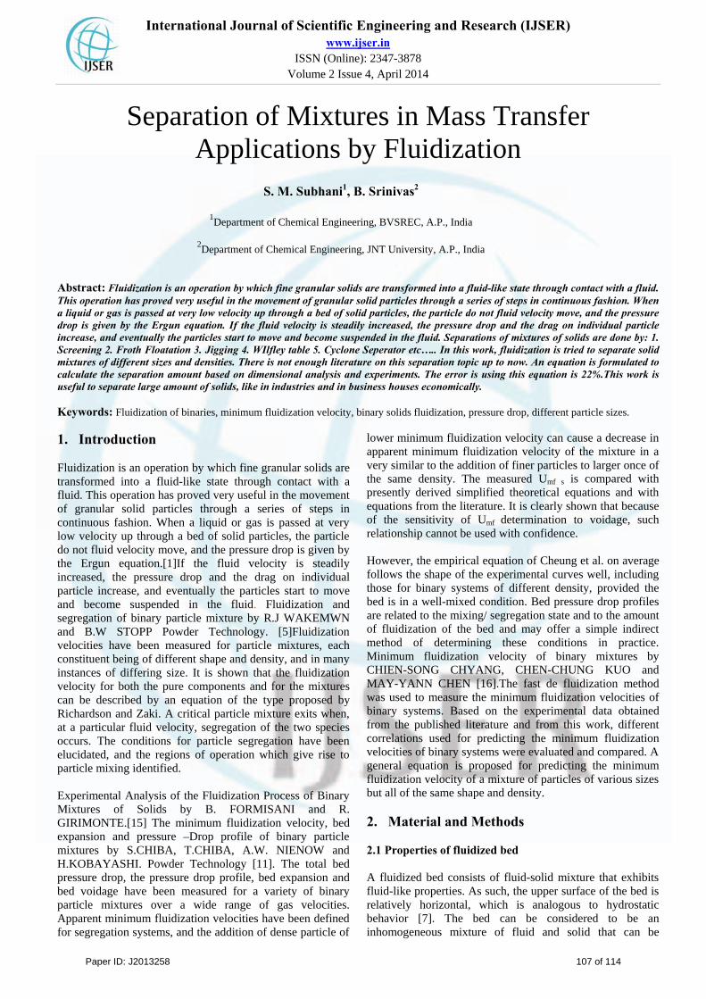
2.4 Design of Fluidized Bed
Figure 1: A Diagram of Fluidized bed
2.5 Basic Model When the packed bed has a fluid passed over it, the pressure drop of the fluid is approximately proportional to the fluid's superficial velocity.[2] In order to transition from a packed bed to a fluidized condition, the gas velocity is continually raised. For a free-standing bed there will exist a point, known as the minimum or incipient fluidization point, whereby the bed's mass is suspended directly by the flow of the fluid stream. The corresponding fluid velocity, known as the "minimum fluidization velocity", . Beyond the minimum fluidization velocity ( ), the bed material will be suspended by the gas-stream and further increases in the velocity will have a reduced effect on the pressure, owing to sufficient percolation of the gas flow. Thus the pressure drop from for is relatively constant. At the base of the vessel the apparent pressure drop multiplied by the cross-section area of the bed can be equated to the force of the weight of the solid particles (less the buoyancy of the solid in the fluid).
2.6 Review of Fluidization Basics Fluidization is a process in which solids are caused to behave like a fluid by blowing gas or liquid upwards through the solid-filled reactor. Fluidization is widely used in commercial operations; the applications can be roughly
divided into two categories, i.e. physical operations such as transportation, heating, absorption, mixing of fine powder and chemical operations such as reactions of gases on solid catalysts and reactions of solids with gases etc.
2.7 Fluidization Regimes
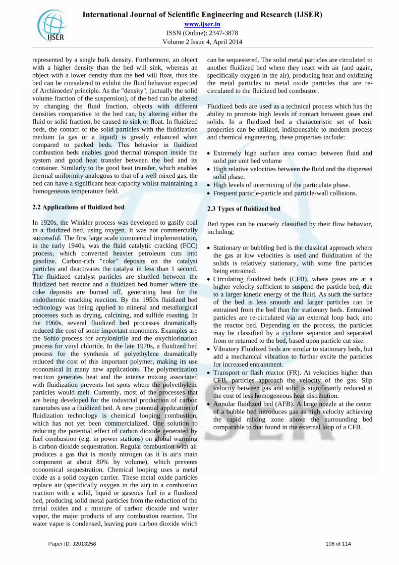
When the solid particles are fluidized, the fluidized bed behaves differently as velocity, gas and solid properties are varied. It has become evident that there are number of regimes of fluidization, as shown in below figure. When the flow of a gas passed through a bed of particles is increased continually, a few vibrate, but still within the same height as the bed at rest. This is called a fixed bed. With increasing gas velocity, a point is reached where the drag force imparted by the upward moving gas equals the weight of the particles, and the void age of the bed increases slightly: this is the onset of fluidization and is called minimum fluidization with a corresponding minimum fluidization velocity, Umf. Increasing the gas flow further, the formation of fluidization bubbles sets in at this point, a bubbling fluidized bed occurs as shown in below figure. As the velocity is increased further still, the bubbles in a bubbling fluidized bed will coalesce and grow as they rise[6]. If the ratio of the height to the diameter of the bed is high enough, the size of bubbles may become almost the same as diameter of the bed. This is called slugging. If the particles are fluidized at a high enough gas flow rate, the velocity exceeds the terminal velocity of the particles. The upper surface of the bed disappears and, instead of bubbles, one observes a turbulent motion of solid clusters and voids of gas of various sizes and shapes. Beds under these conditions are called turbulent beds as shown in below figure. With further increases of gas velocity, eventually the fluidized bed becomes an entrained bed in which we have disperse, dilute or lean phase fluidized bed, which amounts to pneumatic transport of solids.
Figure 2: Schematic representation of fluidized beds in different regimes
Paper ID: J2013258 109 of 114
International Journal of Scientific Engineering and Research (IJSER)www.ijser.in
ISSN (Online): 2347-3878 Volume 2 Issue 4, April 2014
There are two types of basic fluid bed designs according to the solids flow pattern in the dryer. (1) The continuous back-mix flow design for feeds that
require a degree of drying before fluidization is established.
(2) The plug flow design for feeds that is directly fluidizable on entering the fluid bed
Transport of the solids through the fluid bed may be achieved either by the fluidization alone or a combination of fluidization and vibration. The flow of gas relative to the solids is characterized either as cross flow in a single tier fluid bed or as cross/counter-current in a multi-tier fluid bed.
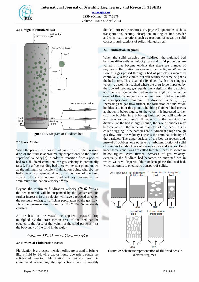
2.7.1 Back-Mix Flow Fluid Beds
Figure 3: Back-mix flow fluid bed
These are applied for feeds that are non-fluidizable in their original state, but become fluidizable after a short time in the dryer, e.g. after removal of surface volatiles from the particles [10]. The condition of the fluidizing material is kept well below this fluidization point. Proper fluidization is obtained by distributing the feed over the bed surface and designing the fluid bed to allow total solids mixing (back-mix flow) within its confines. The product temperature and moisture are uniform throughout the fluidized layer. Heating surfaces immersed in the fluidized layer improve the thermal efficiency and performance of this system. Back-mix fluid beds of both rectangular and circular designs are available 2.7.2 Plug Flow Fluid Beds
Figure 4: Plug flow fluid beds
These are applied for feeds that are directly fluidizable. Plug flow of solids is obtained by designing the fluid bed with baffles to limit solids mixing in the horizontal direction.
Thereby the residence time distribution of the solids becomes narrow. Plug flow fluid beds of either rectangular or circular designs are especially used for removal of bound volatiles or for heating and cooling. The volatile content and temperature vary uniformly as solids pass through the bed, and the plug flow enables the solids to come close to equilibrium with the incoming gas [17]. Plug flow may be achieved in different ways depending upon the shape and size of the bed. In rectangular beds, baffles are often arranged to create an
alternating flow of solids from side to side. In circular beds, baffles are spiral. In relatively small
circular beds with high powder layers, baffles are radial
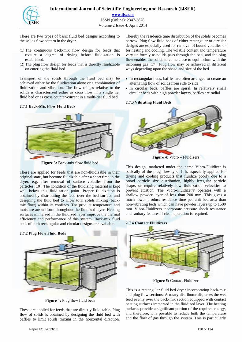
2.7.3 Vibrating Fluid Beds
Figure 4: Vibro – Fluidizers
This design, marketed under the name Vibro-Fluidizer is basically of the plug flow type. It is especially applied for drying and cooling products that fluidize poorly due to a broad particle size distribution, highly irregular particle shape, or require relatively low fluidization velocities to prevent attrition. The Vibro-Fluidizer® operates with a shallow powder layer of less than 200 mm. This gives a much lower product residence time per unit bed area than non-vibrating beds which can have powder layers up to 1500 mm. Vibro-Fluidizers incorporate pressure shock resistance and sanitary features if clean operation is required.
2.7.4 Contact Fluidizers
Figure 5: Contact Fluidizer This is a rectangular fluid bed dryer incorporating back-mix and plug flow sections. A rotary distributor disperses the wet feed evenly over the back-mix section equipped with contact heating surfaces immersed in the fluidized layer. The heating surfaces provide a significant portion of the required energy, and therefore, it is possible to reduce both the temperature and the flow of gas through the system. This is particularly
Paper ID: J2013258 110 of 114
International Journal of Scientific Engineering and Research (IJSER)www.ijser.in
ISSN (Online): 2347-3878 Volume 2 Issue 4, April 2014
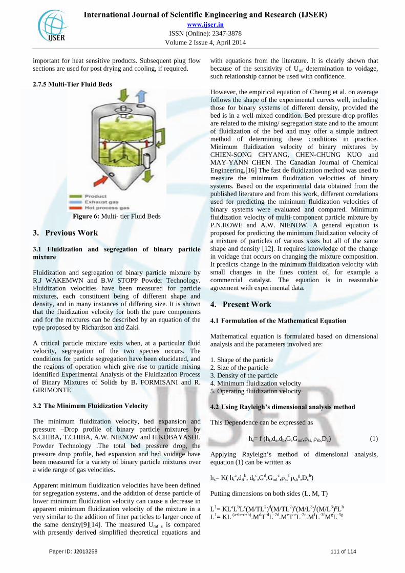
important for heat sensitive products. Subsequent plug flow sections are used for post drying and cooling, if required. 2.7.5 Multi-Tier Fluid Beds
Figure 6: Multi- tier Fluid Beds
3. Previous Work
3.1 Fluidization and segregation of binary particle mixture Fluidization and segregation of binary particle mixture by R.J WAKEMWN and B.W STOPP Powder Technology. Fluidization velocities have been measured for particle mixtures, each constituent being of different shape and density, and in many instances of differing size. It is shown that the fluidization velocity for both the pure components and for the mixtures can be described by an equation of the type proposed by Richardson and Zaki. A critical particle mixture exits when, at a particular fluid velocity, segregation of the two species occurs. The conditions for particle segregation have been elucidated, and the regions of operation which give rise to particle mixing identified Experimental Analysis of the Fluidization Process of Binary Mixtures of Solids by B. FORMISANI and R. GIRIMONTE 3.2 The Minimum Fluidization Velocity The minimum fluidization velocity, bed expansion and pressure –Drop profile of binary particle mixtures by S.CHIBA, T.CHIBA, A.W. NIENOW and H.KOBAYASHI. Powder Technology .The total bed pressure drop, the pressure drop profile, bed expansion and bed voidage have been measured for a variety of binary particle mixtures over a wide range of gas velocities. Apparent minimum fluidization velocities have been defined for segregation systems, and the addition of dense particle of lower minimum fluidization velocity can cause a decrease in apparent minimum fluidization velocity of the mixture in a very similar to the addition of finer particles to larger once of the same density[9][14]. The measured Umf s is compared with presently derived simplified theoretical equations and
with equations from the literature. It is clearly shown that because of the sensitivity of Umf determination to voidage, such relationship cannot be used with confidence. However, the empirical equation of Cheung et al. on average follows the shape of the experimental curves well, including those for binary systems of different density, provided the bed is in a well-mixed condition. Bed pressure drop profiles are related to the mixing/ segregation state and to the amount of fluidization of the bed and may offer a simple indirect method of determining these conditions in practice. Minimum fluidization velocity of binary mixtures by CHIEN-SONG CHYANG, CHEN-CHUNG KUO and MAY-YANN CHEN. The Canadian Journal of Chemical Engineering.[16] The fast de fluidization method was used to measure the minimum fluidization velocities of binary systems. Based on the experimental data obtained from the published literature and from this work, different correlations used for predicting the minimum fluidization velocities of binary systems were evaluated and compared. Minimum fluidization velocity of multi-component particle mixture by P.N.ROWE and A.W. NIENOW. A general equation is proposed for predicting the minimum fluidization velocity of a mixture of particles of various sizes but all of the same shape and density [12]. It requires knowledge of the change in voidage that occurs on changing the mixture composition. It predicts change in the minimum fluidization velocity with small changes in the fines content of, for example a commercial catalyst. The equation is in reasonable agreement with experimental data.
4. Present Work
4.1 Formulation of the Mathematical Equation Mathematical equation is formulated based on dimensional analysis and the parameters involved are: 1. Shape of the particle 2. Size of the particle 3. Density of the particle 4. Minimum fluidization velocity 5. Operating fluidization velocity 4.2 Using Rayleigh’s dimensional analysis method This Dependence can be expressed as
hs= f (ht,ds,db,G,Gmf,ρss, ρsb,Dc) (1) Applying Rayleigh’s method of dimensional analysis, equation (1) can be written as hs= K( ht
a,dSb, db
c,Gd,Gmfc,ρss
f,ρsb
g,Dch)
Putting dimensions on both sides (L, M, T) L1= KLaLbLc(M/TL2)d(M/TL2)e(M/L3)f(M/L3)gLh
L1= KL (a+b+c+h).MdT-dL-2d.MeT-eL-2e.MfL-3fMgL-3g
Paper ID: J2013258 111 of 114
International Journal of Scientific Engineering and Research (IJSER)www.ijser.in
ISSN (Online): 2347-3878 Volume 2 Issue 4, April 2014
Collecting powers L1=L(a+b+c+h-2d-2e-3f-3g).M(d+e+f+g).T(-d-c) Equating powers on both sides we get a+b+c+h-2d-2e-3f-3g= 1………….(a) d+e+f+g= 0………….(b) From (b) d+e = - (f+g)…...(c) -d-e= 0………… (d)
d = -e ……...... (e) Substituting (d) in (c) we get: f = -g …………….. (f) Substituting the value in equation (1) we get; hs = K ht
adsb db
cDch(Gmf/G)e(ρsb/ρss)
g
= K hta ds
b dbcDc
(1-a-b-c)(Gmf/G)e(ρsb/ρss)g
hs /Dc = K (ht/Dc)a(ds/Dc)
b(db/Dc)c(Gmf/G)e(ρsb/ρss)
g
The final equation is hs/Dc=K[(ht/Dc)
a(ds/Dc)b(db/Dc)
c(Gmf/G)e(ρsb/ρss)g]n (2)
5. Experimental Work The schematic diagram of the experimental set-up is shown in fig-1.A Glass column of 1.9 cm (id), 1m length, 3mm thickness was used as a packed bed. A porous mesh provided at the bottom of the column, to provide the support to the material and uniform distribution of air in the column. Each component in this experiment is close- sieved to give a narrow size distribution [4]. Required quantity of the material is charged into the column at top, and measure the total height of the material in column. Compressed air was sent through the column, the flow rate of the air was controlled by using valve. The flow rate of air in the column was measured by using a U-Tube manometer to give a pressure drop. Compressed air was sent through the column at certain flow rate, at which flow the pressure drop occurred in the fixed bed column considered as a minimum fluidization velocity. At minimum fluidization the total fixed bed in the column should be in motion. Measure the pressure drop reading in U-Tube manometer, and increase the flow of compressed air to 1.5 times pressure drop to minimum fluidization velocity pressure drop. Continue the air flow rate until the bed becomes saturated. Stop the air flow by switch off the compressor, and take the readings after the material settle down.
5.1 For Power of a
5.1.1Material Preparation Step1: Take two different diameters and having the same density materials, which are close-sieve material to give the narrow size distribution Step2: The two materials are 1. Passing through #6 and retains on#12, which having the
average dia of 0.85mm.
2. passing through #18 and retains on #30, which having the average dia of 0.68 mm
5.1.2Procedure 1. Take 50% of each material and mix properly. 2. Charge the mixed material into the glass fluidizing
column and note down the total bed height of the material inside column and add to the desired total bed height.
3. Switch on the blower and measure the minimum fluidization velocity (Gmf).
4. Adjust the operating fluidization velocity to 1.5 times the minimum fluidization velocity.
5. Continue the fluidization until steady state is reached. 6. Switch off the blower and get the material to settle down. 7. Take the readings of height of small dia material
separated (hs) and record the values in a given table. 8. Repeat the same procedure for different total quantities of
materials and take the readings of hs.
5.2 For Power of b
5.2.1Material preparation Step1: Take 4 different sizes of having the same density of close-sieved material Step2: Calculate the average diameter of each material and listed them
5.2.2Procedure 1. Take some quantity of big dia material 2. Take some quantity of small dia material 3. Mix the both materials and charge into the glass column,
measure the total bed height.4. Switch on the blower and measure the minimum
fluidization velocity (Gmf). 5. Adjust the operating fluidization velocity to 1.5 times the
minimum fluidization velocity. 6. Continue the fluidization until steady state is reached 7. Switch off the blower and get the material to settle down. 8. Take the readings, height of small dia material hs record
the values in a given table
5.3 For Power of c
5.3.1Material preparation Step1: Take 4 different sizes of having the same density of close-sieved material. Step2: Calculate the average diameter of each material and listed
5.3.2Procedure 1. Take some quantity of big dia material. 2. Take some quantity of small dia material. 3. Mix the both materials and charge into the glass column,
measure the total bed height inside the column. 4. Switch on the blower and measure the minimum
fluidization velocity (Gmf). 5. Adjust the operating fluidization velocity to 1.5 times the
minimum fluidization velocity G=1.5*Gmf 6. Continue the fluidization until steady state is reached. 7. Switch off the blower and gets the material to settle
down.
Paper ID: J2013258 112 of 114

International Journal of Scientific Engineering and Research (IJSER)www.ijser.in
ISSN (Online): 2347-3878 Volume 2 Issue 4, April 2014
8. Note down the readings of height of small diameter material hs and record the values in a given table.
9. Repeat the same procedure for different diameter of big size material without changing the small diameter material.
5.4 For Power of e
5.4.1Material preparation Step1: Take 2 different sizes, having the same density of close-sieved material. Step2: Calculate the average diameter of each material and listed
5.4.2Procedure 1. Take 15g of each material and mix properly. 2. Mix the both materials and charge into glass column,
measure the total bed height inside the column. 3. Switch on the blower and measure the minimum
fluidization velocity (Gmf). 4. Adjust the operating fluidization velocity to 1.5 times the
minimum fluidization velocity. 5. Continue the fluidization until steady state is reached. 6. Switch off the blower and gets the material to settle down. 7. Note down the readings of height of small diameter solids
hs and record the values in a given table. 8. Repeat the same procedure for different operating
fluidization velocities like 2 times & 2.5 times of Gmf.
5.5 For Power of g
5.5.1Material preparation Step1: Take 4 different types of materials having different densities. Step2: Each material should be closely sieved. Step3: Calculate the average diameter of each material and listed
5.5.2Procedure 1. Take 20g of each material and mix properly. 2.Mix the both materials and charge into glass column,
measure the total bed height inside the column. 3. Switch on the blower and measure the minimum
fluidization velocity Gmf. 4. Adjust the operating fluidization velocity to 1.5 times the
minimum fluidization velocity. 5. Continue the fluidization until steady state is reached. 6. Switch off the blower and gets the material to settle down. 7. Note down the readings of height of small diameter solids
hs and record the values in a given table. 8. Repeat the same procedure for different density material
and maintain there maining parameters/volumes are as constant.
6. Results and Discussion
For Power of a S.No 1 2 3 hs 3.0 4.4 5.7 ht 8.0 12.2 14.7 hs/Dc 1.57 2.32 3.0 ht/D 4.21 6.42 7.73 ws 10 15 18 wb 10 15 18 log(hs/Dc) 0.19 0.37 0.47 log(ht/Dc) 0.62 0.80 0.88 Gmf 2.6 4.2 4.7 Goper 3.9 6.3 7.0
For Power of b S.No 1 2 3 4 hS 3.7 4.0 4.5 4.9 ht 8 8 8 8 ds 0.068 0.045 0.040 0.032 hs/Dc 1.94 2.11 2.36 2.57 ds/Dc 0.035 0.023 0.021 0.016 log(hs/Dc) 0.29 0.32 0.39 0.41 log(ds/Dc) -1.46 -1.64 -1.68 -1.80
For Power of c S.No 1 2 3 4 hs 2.8 3.8 4.4 4.8 ht 8.0 8.0 8.0 8.0 db 0.21 0.068 0.045 0.039 db/Dc 0.11 0.035 0.024 0.019 hs/Dc 1.48 2.0 2.32 2.52 log(db/Dc) -0.96 -1.46 -1.62 -1.72 log(hs/Dc) 0.17 0.30 0.37 0.4
For Power of e S.No 1 2 3 ht 12.2 12.2 12.2 Gmf 4.2 4.2 4.2 G 6.3 8.4 10.5 Gmf/G 0.67 0.50 0.40 hs 4.2 4.8 5.2 hs/Dc 2.21 2.53 2.74 log(hs/Dc) 0.34 0.40 0.44 Log(Gmf/G) -0.17 -0.30 -0.40
For Power of g S. No 1 2 3 ht 12.2 12.2 12.2 Gmf 4.2 4.2 4.2 G 6.3 8.4 10.5 Gmf/G 0.67 0.50 0.40 hs 4.2 4.8 5.2 hs/Dc 2.21 2.53 2.74 log(hs/Dc) 0.34 0.40 0.44 Log(Gmf/G) -0.17 -0.30 -0.40
Paper ID: J2013258 113 of 114
International Journal of Scientific Engineering and Research (IJSER)www.ijser.in
ISSN (Online): 2347-3878 Volume 2 Issue 4, April 2014
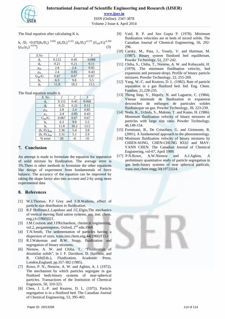
The final equation after calculating K is hs /Dc =0.07[(ht/Dc)
0.995 (ds/Dc)-0.325 (db/Dc)
-0.279 (Gmf/G)-0.399
(ρsb/ρss) 0.074] (3)
S.No 1 2 3
ds 0.112 0.45 0.068 db 0.21 0.21 0.11 ρsb 2.8 2.4 0.85 ρss 2.4 0.85 0.43
Gmf/G 0.67 0.67 0.67 hs 6.3 9.8 5.5 ht 11.8 18.2 13.5
The final equation results is S. No 1 2 3
ds 0.112 0.45 0.068 db 0.21 0.21 0.11 ρsb 2.8 2.4 0.85 ρss 2.4 0.85 0.43
Gmf/G 0.067 0.67 0.67 hs 6.3 9.8 5.5 ht 11.8 18.2 13.5
(hs /Dc)equ 2.36 5.4 3.8 (hs /Dc)obs 3.31 5.1 2.9 % error 29 -6 -31
7. Conclusion An attempt is made to formulate the equation for separation of solid mixture by fluidization. The average error is 3%.There is other methods to formulate the other equations like design of experiment from fundamentals of force balance. The accuracy of the equation can be improved by taking the shape factor also into account and 2-by using more experimental data
8. References
[1] W.J.Thomas, P.J Grey and S.B.Watkins, effect of particle size distribution in fluidization.
[2] R.F Hoffman,L.Lapiduus and J.C.Elgin,The mechanics of vertical moving fluid sation systems. am. inst. chem. eng.j.6 (1960)321.
[3] J.M.Coulson and J.FRichardson, chemical engineering, vol.2, pergamonpress, Oxford, 2nd edn.1968
[4] T.N.Smith, The sedimentation of particles having a dispersion of sizes, trans.inst.chem.eng,44(1966)T153
[5] R.J.Wakeman and B.W. Stopp, fluidization and segregation of binary mixtures.
[6] Nienow, A. W. and Chiba, T.: “Fluidization of dissimilar solids”, in J. F. Davidson, D. Harrison, and R. Clift(Eds.), Fluidization, Academic Press, London,England, pp.357-382 (1985).
[7] Rowe, P. N., Nienow, A. W. and Agbim, A. J. (1972). The mechanism by which particles segregate in gas fluidized beds-binary systems of near-spherical particles. Transactions of the Institution of Chemical Engineers, 50, 310-323.
[8] Chen, J. L.-P. and Keairns, D. L. (1975). Particle segregation is in a fluidized bed. The Canadian Journal of Chemical Engineering, 53, 395-402.
[9] Vaid, R. P. and Sen Gupta P. (1978). Minimum fluidization velocities are in beds of mixed solids. The Canadian Journal of Chemical Engineering, 56, 292-296.
[10] Carsky, M., Pata, J., Vesely, V. and Hartman, M. (1987). Binary system fluidized bed equilibrium. Powder Technology, 51, 237-242.
[11] Chiba, S., Chiba, T., Nienow, A. W. and Kobayashi, H. (1979). The minimum fluidisation velocity, bed expansion and pressure-drop). Profile of binary particle mixtures. Powder Technology, 22, 255-269.
[12] Yang, W.-C. and Keairns, D. L. (1982). Rate of particle separation in a gas fluidized bed. Ind. Eng. Chem. Fundam, 21,228-235.
[13] Thong limp, V., Hiquily, N. and Laguerie, C. (1984). Vitesse minimale de fluidization et expansion descouches de mélanges de particules solides fluidiséespar un gaz. Powder Technology, 39, 223-239.
[14] Noda, K., Uchida, S., Makino, T. and Kamo, H. (1986). Minimum fluidization velocity of binary mixtures of particles with large size ratio. Powder Technology, 46,149-154.
[15] Formisani, B., De Cristofaro, G. and Girimonte, R. (2001). A fundamental approach to the phenomenology.
[16] Minimum fluidization velocity of binary mixtures by CHIEN-SONG, CHEN-CHUNG KUO and MAY-YANN CHEN. The Canadian Journal of Chemical Engineering, vol-67, April 1989.
[17] P.N.Rowe, A.W.Nienow and A.J.Agbim, A preliminary quantitative study of particle segregation in gas beds-binary systems of near spherical particals, trans.inst,chem engg.50(1972)324.
Paper ID: J2013258 114 of 114