separation metal droplets trom slag penny iwamasa fruehan
TRANSCRIPT
ISIJ International, Vol. 36 (1 996), No. 11, pp. 131 9-1 327
Separation of Metal Droplets trom Slag
PennyK.
Center for
Pittsburgh,
IWAMASAand Rlchard J. FRUEHANlron and Steelmaking Research, Department of Materials Science and Engineering,
PA1521 3, USA.
(Received on February 16. 1996.• accepted in final form on July 15. 1996)
Carnegie Mellon University.
Themotion of liquid metal droplets in molten slags wasstudied using low temperature physical modelingand X-ray observations at high temperatures. Experiments were done to assess settling times of metaldroplets in slags. Experimental work included oil and water modeling and high temperature experimentsutilizing a furnace equipped with an X-ray fluoroscopy apparatus. Results showthat settling times of metaldroplets in stagnant slags and water droplets in a variety of oils can be accurately predicted utilizing Stokes'equation modified for the appropriate experimental conditions. It wasalso found that gas stirring in slags,
whether by chemical reaction or gas injection, and slag foaming increases droplet settling times. Stablefoams resulting from the reaction of FeOin the slag and carbon in the metal as well as gas injection in themetal phase caused rafts to form which could permanently hold droplets up to about 5mmin diameter at
the top of the slag. For better separation, slags with low viscosities are recommendedand foaming shouldbe avoided.
KEYWORDS:slag; desulfurization; phase separation,
l .Introduction
Hot metal desulfurization is the process where sulfuris removedfrom metal exiting the iron blast furnace be-fore it is sent to the steelmaking converter. In typical
desulfurization practices, a reagent is injected through asubmergedlance with a carrier gas. During injection,
metal droplets are thrown up into the slag phase andentrained. After desulfurization is completed, the topslag is skimmedoff before the hot metal is taken to the
steelmaking furnace to stop sulfur reversion, r) Iron lo~ses
due to droplets entrained in the post-desulfurization slag
and from splashing during slag removal can be as high
as 2.5 o/o of the total hot metal weight and account for
one of the major costs for desulfurization.2)
One way to decrease the yield loss due to metalentrained in the slag is simply to use less desulfurizing
reagent so that fewer metal droplets get entrained andless slag mustbe removed. This is not easily donebecause
a sufficient amount of slag is needed for satisfactory
desulfurization in a reasonable amountof time. Another
wayof decreasing yield loss is to improve the physical
properties of the slag to promote better separation be-
tween the slag and metal phases. This is donewith var-ious slag conditioners that are either injected with the
desulfurizing reagent or added to the slag whendesul-
furization is cornpleted and before the slag is skimmed.3)Theseslag conditioners mayinclude oneof the following:
fluorspar, borax, soda ash, iron oxide, and steelmakingslag. Before waysof decreasing yield losses can be sug-gested, a fundamental understanding of the process ofmetal droplets settling through slag and getting incor-
131 9
porated into the metal phase must be obtained and is
addressed in this research. This study includes experi-
mental work in the oil/water modeling system, oil rep-resenting slag, and water representing metal, as well ashigh temperature X-ray fluoroscopy experiments whereexperiments conducted at elevated temperatures (1 450-l 500'C) are visualized.
2. Experimental
2.1. Oil/Water ModelingOil and Water: The physical properties of water
were taken from the CRCHandbookof Chemistry andPhysics4) and properties of the oil phaseweredeterminedusing the appropriate techniques. The densities of theoils were calculated by weighing 100ml of the oil in agraduated cylinder at a given temperature. Theviscosity
of the oil was determined using the ASTMD 445-88Standard Test Methodfor Kinematic Viscosity of Trans-parent and OpaqueLiquids. Asummaryof the physicalproperties of the oils used in the single phaseexperimentsand the oil mixtures is presented in Table 1.
Plastic Spheres: Polypropylene spheres used to sim-ulate a solid second phase of a two phase slag wereobtained in two diameters and colors, 6.35mm(green)
and 9.53mm(blue) from Hoover Precision Products.
Twomixtures of heavy and light paraffin oils were usedas the liquid phase in these experiments and designed sothat the spheres were suspendedin the oil phase. Mix Awas used for the 6.35mmspheres and Mix Bwas usedfor the 9.53 mmspheres. Volumefractions of solid phaseincluded 3.3, 6.6, 13, and20 o/o solids for eachsphere size.
@1996 ISIJ

ISIJ International, Vol.
Table 1. Physical properties ofwater and oils used in watermodeling experiments.
Phase Densit ( /cm3) Viscosit (P
Li ht Paraffm Oil 0.858 0.327 (30.2' C)
Hea Paraffin Oil 0.880 1.08 (30.2' C)
Cottonseed Oil 0.917 0.442 (30.2' C)
Silicon Oil 0.961 0.425 (30.2' C)
Oil Mix A 0.877 1.50 (22' C)
Oil Mix B o872 l.1 1(21' C)
Water (20' C) 0.99823 0.0 1002
Water (30' C) 0.99567 0.007975
36 (1 996), No. 11
Graphite TubeGuide
Alumina Furnace TubeTube
~Crucible
Mullite Tube
Image Intensifier
O~ ~ ~
e~_lFl
_~~VTCOR
X-Ray ~-= BrickAluminumSouroeFo'l
CeramicFiber
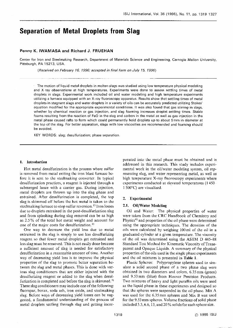
Fig. l. Schematic diagram of furnace used for high tempera-ture experiments equipped with X-ray fluoroscope
apparatus.
Table 2. X-ray analysis of the slags used in the high tem-perature X-ray fluoroscopy experiments.
Experimental Procedure: Amodelwith inner dimen-sions 75mmx 75mmx 295mmhigh wasconstructed us-ing 3mmthick Plexiglas. A Icmsquare grid wasplacedat the back of the model. Themodelwasused to containthe oil and oil/sphere mix with a layer of colored waterat the bottom. A 5cc disposable syringe with a size 16
gaugebeveled needle wasused to introduce the colored
water droplets just below the surface of the oil. Avideosystem consisting of a camera, a video cassette recorder(VCR), and a monitor wasused to video tape the experi-
ments so that analysis could be done after the experi-
ments were completed. Experiments were also carried
out in the system of water and cottonseed oil in a72cmlong quartz glass tube with a diameter of 2.43 cmhoused in a Plexiglas box which wasalso filled with oil.
Experiments wereconducted wherea solution of colored
water wasdropped into the oil either using a syringe orstraw as close to the centerline of the tube as could bevisually determined.
2.2. High Temperature X-ray Fluoroscopy
Slags: Amixture of reagent grade powdersof 100/.
A1203, 36~/* CaO,and 54"/o Si02 for slag I and 100/.
A1203, 300/* CaO,and 60"/* Si02 for slag 11 was usedfor the X-ray fiuoroscopy experiments. A 75 kWinduc-tion furnace wasused for melting both slags which werecontained in high density alumina crucibles. Theslag wasallowed to cool to room temperature and crushed. APhillips X-RayFluorescence Spectrograph was used todetermine the amountof oxides in the slag and the results
are presented in Table 2.
Metals: Iron chips were inductively melted in agraphite crucible and cast in a copper mold. The result-
ing "slugs" of iron alloy were removedfrom the mold,sandblasted to removed surface oxidation, and ultra-
sonically cleaned. Nickel was obtained in 3.2mmdi-
Table 3. Physical properties of slag and metal used in high
temperature X-ray fluoroscopy experiments.
C 1996 ISIJ
Phase Temperature ('C) Density
( cm~3)
Viscosity
(P)
Sla I l450 2.6 5) 22,~ 6)
1:7pCsat l~v l450 677 7) 0.058 8)
Sla II l500 2.445 5) 41.05 6)
Nickel l500 777 4) 0,043 9)
1320
ameter rods which were cut into pieces of about 2cmin length.
Furnace and X-ray Fluoroscopy: The high temper-ature slag metal separation experiments were carried
out in a furnace equipped with an X-ray fiuoroscopyapparatus that allowed the experiments to be viewed andvideo taped. A schematic of the apparatus is presentedin Fig. 1. In these experiments, an alumina crucible
(32mmI.D., 38mmO.D., 152rnmH., closed round atbottom) was attached to a guide tube using aluminacement, placed in a resistance furnace and slowly heated.
Experimental Procedure: Onceat the desired tempera-ture (1 450'C for carbon saturated iron experiments andl 500'C for the nickel experiments), the slag wasaddedvia a guiding tube and kept there for about 10min tomelt and homogenize. The carbon saturated iron slugs
were introduced to the liquid slag by meansof a graphitepipe fitted with nozzles of varying exit diameters. Afterbeing dropped down the length of the pipe, the slug
stopped falling at the junction where the nozzle and the
tube met as the diameter of that area is smaller than thediameter of the slug. It slowly melted and traveled downthe nozzle wheredroplets of the metal exited the openingof the nozzle.
In the experiments where nickel was used, aluminatubes were used as a container to melt the nickel metalandform the droplet. Alumina tubes of varying diameters
(4lO mmI.D., 610mmL.) which wereclosed at oneend
weredrilled with a diamondbit of varying sizes (2-6 mm)at the tip of the closed end. The physical properties
ISIJ International, Vol. 36 (1 996), No. 11
of the slag and metal used for these experiments arepresented in Table 3.
Someexperiments required argon bubbling. This wascarried out by a lance madefrom an alumina tube (4 mmI.D., 6mmO.D., 762mmL., closed round at bottom).The tube was drilled with a diamond bit and fitted
and cementedwith a smaller diameter (1 mm)aluminacylinder of a length of 5mm.The angle of exit of the
gas bubbles was90' from the tube length.
2.3. Data Analysis
The settling times of the iron and nickel dropletstraveling through the slag and the water droplets settling
through the oil were measuredby computer analysis ofthe video tape. Imageanalysis wasperformed on a com-puter using the public domainNlH Imageprogram.10)
The software program wasused to find the diarneter ofthe settling droplet and the distance the droplet traveled.
3. Equations for Predicting Settling Velocities
3.1. Stokes' Equation
As a first approximation, the motion of liquid metaldroplets in molten slags is estimated as exhibiting be-
havior in Stokes' regime.1 1) Stokes' equation can be usedto determine the terminal settling velocities of these metaldroplets in the slags and is developed basedon the force
balance between the weight of the droplet and its dragand buoyancyas shownbelow.
Vst.kes =9d2( p~- p~)
. . . .. . . ...( I)18~~
where, Vs*~k.* : Terminal velocity of droplet (cms~1),
g: Acceleration due to gravity (9.8lms~2),d: Droplet diarneter (cm),
p~ : Slag density (g cm~ 3),
p* : Metal density (g cm~3), and
n: Viscosity of slag (Poise).
Thederivation of Stokes' equation is basedon several
assumptions including, incompressibility of the medium,infinite extent of the medium,rigidity of the falling object,
andabsenceof slipping at the interface betweenthe metaldroplet and the slag.
Because of the difficulty satisfying all of the aboveconditions in practice, the assumptions of Stokes' equa-tion in the context of the physical system used in this
study should be discussed. Incompressibility of the
mediumis an assumption that is generally valid in the
system of metal droplets in the slags. Physical experi-
mental limitations such as crucible walls may affect
the assumption of an infinite extent of the mediumandthe affect of the confining wall w. ill decrease the predictedvelocity. A small and constant terminal velocity is animportant criterion to meet in the derivation of Stokes'
equation and is discussed in the following section in termsof the Reynolds Number. Since they are liquid, metaldroplets are free to deform (e.g. internal circulation)
during descent which increases the predicted velocity.
Continuity of velocity across the slag/metal interface mayoccur since the interface is not a rigid one. The liquid
metal droplets mayslip at the interface betweenthe metal
droplet and the slag that it falls through which mayalter
the drag characteristics at the interface. Since the metaldroplets are free to deform, they mayloose their sphericalshape.
3.2. Reynolds NumberThe Reynolds Numberof a system is a dimensionless
numberoften used to characterize flow over immersedbodies.
Re-Psvd
..........(2)
n~
The importance of Re in this system is in calculating
the drag coefficient for the force balance used in thederivation of Stokes' equation. As Re gets larger thanabout unity, the drag coefficient is not a direct functionof the Reynolds numberand there is moredrag on thedroplet than in the ideal Stokes' case. 12) This phenomenawould cause the motion of the droplet to deviate fromStokes' Iaw and the terminal velocity would be lowerthan that predicted from the ideal Stokes' case.
3.3. Transient Behavior
Calcuations were done to determine the amount oftime it would take a metal droplet settling through a slag
(and a water droplet settling through an oil) to reachits terminal velocity. These calculations were based onsolving the transient force balance of the droplet starting
from an initial velocity of zero to the terminal velocity
where the change of velocity as a function of time (for
short times) is taken to bel2~ 14):
dv_
(p*-p,)g..........(3)
dt p*+0.5p~ """
Equation (3) is rearranged to be integrated betweenthe limits: v=0 at t=0 and v=v (the terminal velocity)
at t=t.
f:=0dv-Jdt ..........(4)
_t (p~-ps)9
.
t=0 P~+0.5ps ""'
Substituting Eq. (1) for the velocity in the integratedEq. (4), the time it takes for a droplet from rest to reachits terminal velocity is:
td (p~+0 5p ) ..........(5)
l8n~
It takes a fraction of a second (lO3-l0~2 sec) for adroplet starting from rest to reach its terminal velocity.
This transient time is short comparedto the total settling
time (O.5 to I sec) of the droplet in the high temperatureX-ray fluoroscopy experiments.
3.4. Einstein's Equation
As a first approximation, it is assumedthat a twophase "slag" can be described using Einstein's equationfor a dilute suspension of solid spheres in a liquid.15)
-..........(6)n=n~ l+ ip
..............
where, n: Bulk viscosity of the suspension (Poise),
1321 C 1996 ISIJ

ISIJ Internationa], Vol.
n. : Viscosity of the single phase liquid (Poise),
andip : Volumefraction of solid spheres.
3.5. Deviation from Stokes' Equation
There were three underlying assumptions used in the
derivation of Stokes' equation that were not met in the
high temperature experiments, they are:l) Infinite extent of the medium2) Rigidity of the falling object (droplet does not de-
form)3) Thedrag coefficient is inversely proportional to the
Reynolds Number.Wall Effect Correction (K): Becausethe high tempera-
ture experiments were contained in a crucible of finite di-
mensions, the mediumfor droplet settling (molten slag)
cannot be assumedto be infinite, In the case of the watermodel, the container could be assumedto be large andno correction is necessary. The effect of the proximityof the crucible wall on the settling velocity has to becorrected for in the analysis of the data for these ex-periments. The boundary of the crucible becomesasignificant contribution when the ratio of the dropletdiarneter to the crucible diameter is larger than about0,lO. This effect causes the droplet to settle slower thanpredicted by Stokes' equation. It should be mentionedthat because of experimental limitations, the size of thecrucible used in the experiments could not be increased.
Themost important experimental limitation is the ability
of the X-rays to penetrate the thickness of the slag. If
the crucible diameter is increased in size, the slag will
absorb a significant portion of the incoming X-rays andthe constrast betweenthe metal and slag as collected andrecorded would not be clear. An empirical correlationfor the wall effect is presented below for a sphere falling
at the centerline of the crucible.1 5)
K=[1-( )^sJ
ISIJ International, Vol. 36 (1996), No. 11
oog,.\Eo
>~oo1;
>
10.0
8,0
6.0
4,0
2,0
0,0
- LPHP
e LPo HP
e
o~
0.20 0.40 0.800.60
Droplet Diameter (cm)
Velocity of water droplets in single phase "slag" (oil)
as a function of droplet diameter. Experimental results
as comparedto Stokes' equation.
HP: HeavyParaffin Oil, LP: Light Paraffin Oil.
1.oo
3,0
2.5
oa, 2.0~e
Eo~ 1.5
>oo15 1.0
>
0.5
0.000.0
- - Stoke - no Solids
Stoke - 20Q/. Solids
e 3.3'/. Soiids
o 6.70/. Solids
~ 130/. Solids
I 200/0 Solids
Fig. 2.
' ~' -i !~ !,~)~~~
jd)....
,
~~e
0.00
Fig. 4.
O. IO 0.20 0.30 0.40 O.50 0.60 O.70 0.80
Droplet Diameter (cm)
Velocity of water droplets in two phase "slag" (oil and6.46mmplastic sphere mix) as a function of droplet
diameter. Experimental results as comparedto Stokes'
equation for no and 20"/* solids utilizing Einstein's
equation.
5,0
4.0 y/ee
4.0
3.5
,\'o
3.0~>o 2.0o~
1,o
l
- /
oO
o
o,oo,oo I ,oo0.800.40 0.600.20
Droplet Diameter (cm)
Fig. 3. Vetocity orwater droplets in single phase "slag" (oil)
as a ftmction ofdroplet diameter. Experimental results
as comparedto Stokes' equation.
CS: Cottonseed Oil, Si: Suicon Oil.
velocity of the water droplet as a function of droplet
diameter is shown. As seen from this plot, the data fol-
10ws Stokes' equation quite well at smaller droplet di-
ameters and deviates from Stokes' equation as the drop-let diameter gets larger. This could be due to the errorin the drag coefficient as the Reynolds Numberof the
droplet increases and from other assumptions that werenot met in the experiments.
TwoPhase "Slag": To simulate a two phase slag,
varying volume fractions of the second phase, poly-
propylene spheres, were suspendedin the oil phase, Figs.
4and 5show the results. These data are comparedto
Stokes' equation for an oil viscosity with no solids andthe oil viscosity based on Einstein's equation for 20 olo
solids. The values used for the viscosity of Mix A andMix Bwith 20 o/o solids are 2.25 and l.67 Prespectively.
It appears that the data is boundby these two theoreti-
cally calculated curves. However, utilizing the results of
Einstein's equation with Stokes' equation maynot beappropriate for the system analyzed. In the development
Oo,o.\Eo
>~oo1;
>
3.0
2,5
2,0
1,5
1.o
0.5
0.0
- - Stoke - no Solids
Stoke - 200/. Solids
o 3.3'/. Solids
o 6.7'/o Solids
A 130/. Solids
l 200/0 Solids
d
o
~
'/1e"1~~ rr-
I : Oll~O~b :_
I
1323
0,00
Fig. 5.
0,20 0,40 0,60 1.OO0.80
Droplet Diameter (cm)
Velocity of water droplets in two phase "slag" (oil and9.53 mmplastic sphere mix) as a function of droplet
diameter. Experimental results as comparedto Stoke's
equation for no and 20"/o solids utilizing Einstein's
equation.
of Stokes' equation, the force balance assumescreepingflow about a sphere where the drag force is proportional
to the viscosity of the mediumin which the sphere is
falling. In the experiments conducted, this darg termwould be the local viscosity (measured viscosity of theoil without the second phase) and not the bulk viscosity
as a result of utilizing Einstein's equation. This wouldbe the case since the size of the droplets are of the sameorder as the suspendedparticles.
The fit of the data to Einstein's equation is probablycoincidental becausethe numberof particles in the liquid
is small and the deviation from the case for a single phaseis small. It is proposed that the droplets obey Stokes'
equation when traveling between particles where the
liquid oil phase governs the viscosity. The droplet thenslows downwhena solid particle is in its path and mayhave enoughmomentumto push the particles out of its
wayor the droplet maycollide with the particle. There
Q1996 ISIJ
ISIJ International, Vol. 36 (1996). No. 11
may be some interfacial phenomenacontrolling this
behavior between the particles and the droplets whichsignificantly effects the setting times and it is probablethat this behavior in oil and water systems maynot bevery useful in accurately assessing this phenomenaforslag and metal systems.
Wall Effect: Lowtemperature experiments were car-ried out to confirm the effect of the wall proximity onthe droplet settling time using cottonseed oil containedin a quartz tube and colored water droplets. The resultsfor these experiments are presented in Fig. 6. Asseen fromthis plot, the experimental results follow the theoreticalprediction quite well.
4.2. High Temperature Experiments
Attempts were madeto form a homogeneoustwophase slag by additions of alumina spheres, fused silica
pieces, and porous lime particles to the molten slags.
These three attempts were unsuccessful, therefore only
2,5
2,0
oo
co
~E 1.5
e~oo 1.015
>0,5
0,0
Stokes' Velocity with Wall Correction
e Experimental Data
,'ti
e
e
ee
e
e
,
0,00
Fig. 6.
0.20 0.40 0.60 0.80 i ,OO I .20
Droplet Diameter (cm)
Experimental resuits showing wall effects on settling
velocities for water droplets in a cylinder of cottonseedoil as comparedto the theoretical calculation.
D*yli~d'* =2.43 cm.
15,0
oo 10.0'o*~Eo:~
oo~ 5.0
0,0
Stokes' Ve]ocity
- - -Wall Effect
••••••••• Wall Effect and Liquid Sphere
e Experimental Data e
" /P~ E,-
d'
d,.
i'l'-
ee ..l
,.
~:
///d'
0,00
Fig. 7.
0,20 0.40 0.60 0.80 1.OO 1Droplet Diameter (cm)
Velocity of carbon saturated droplets in Slag I as afunction of droplet diameter. Experimental results ascomparedto Stoke's equation, Stokes' equation withwall correction, and Stokes' equation with both wallcorrection and liquid sphere correction. T=1450~C.
20
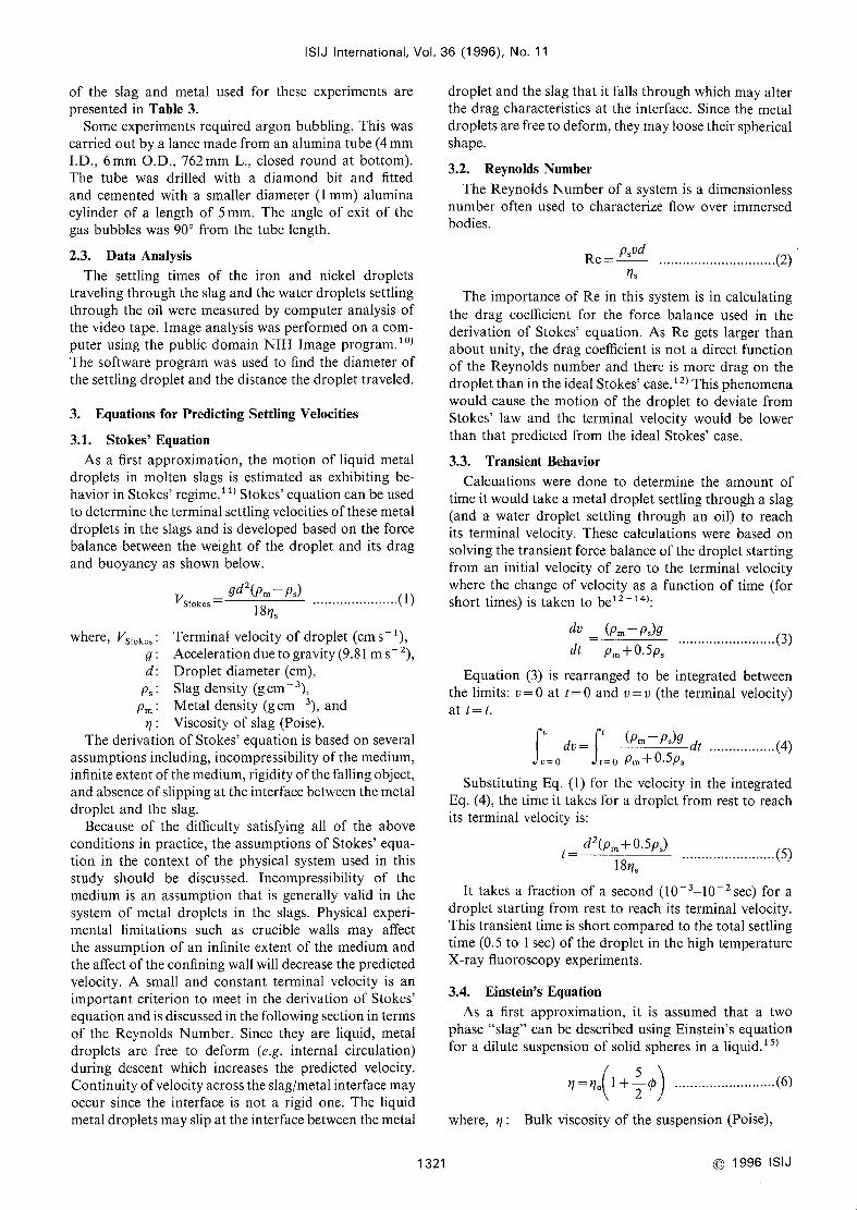
results for single phase slags are presented.Slngle Phase "Slag": The metal droplets stayed
spherical in these high temperature experiments as thewater droplets did in the oils. Figure 7displays the dataobtained from the high temperature, X-ray fluoroscopyexperiment wherecarbon saturated iron and Slag I (35 o/.
CaO, 53"/. SI02, 12~/* A1203) were used at a furnacetemperature of 1450'C. As in the low temperatureanalogs, as the droplet diameter increases, the settlingvelocity also increases. This slag wasa single phase liquidand is comparedwith three theoretical calculations basedon Stokes' equation which include Stokes' equation withno modifications, wall effect, and both wall effect andliquid sphere effects. As seen from Fig. 7, the wall effect
and the liquid sphere effect opposed each other andvirtually canceled out. The significant amountof scatterin this data is due to the fact that the settling distances
were quite small (about 4cm) and the settling times werealso small (about half a second) so when the settlingvelocity is calculated, a large uncertainty results.
It was found that under certain experimental condi-tions, a significant amountof slag foaming occurred. Thecause of the slag foaming wasattributed to the formationof an oxide on the iron particles as they were beingintroduced to the slag. As the particle melted and exitedthe graphite nozzle, the iron oxide would react with thecarbon in the metal and produce a gas, most likely car-bon monoxide. As discussed by Zhangand Fruehan,17)slags formed by a chemical reaction such as Eq. (12)consists of small (average diameter on the order of1mm)spherical bubbles and are quite stable. The foamindex which is related to the foam life or stability wasfound to be inversely proportional to the foam bubblesize. Theproposed chemical reaction that wasoccurringis:
(FeO)+~; =Fe(1) +CO(g) .................(1 2)
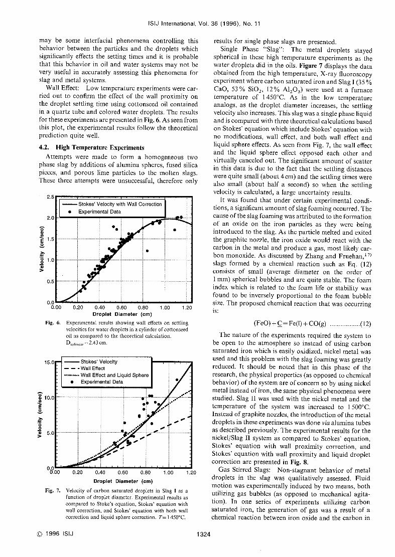
The nature of the experiments required the system tobe open to the atmosphere so instead of using carbonsaturated iron which is easily oxidized, nickel metal wasused and this problem with the slag foaming wasgreatlyreduced. It should be noted that in this phase of theresearch, the physical properties (as opposedto chemicalbehavior) of the system are of concern so by using nickelmetal instead of iron, the samephysical phenomenawerestudied. Slag 11 was used with the nickel metal and thetemperature of the system was increased to 1500'C.Instead of graphite nozzles, the introduction of the metaldroplets in these experiments wasdonevia alumina tubesas described previously. Theexperimental results for thenickel/Slag 11 system as comparedto Stokes' equation,Stokes' equation with wall proximity correction, andStokes' equation with wall proximity and liquid dropletcorrection are presented in Fig. 8.
GasStirred Slags: Non-stagnant behavior of metaldroplets in the slag was qualitatively assessed. Fluidmotion wasexperimentally induced by two means, bothutilizing gas bubbles (as opposed to mechanical agita-tion). In one series of experlments utilizing carbonsaturated iron, the generatlon of gas was a result of achemical reaction between iron oxide and the carbon in
C 1996 ISIJ 1324

6,0
5.0
oo 4'O,o'hEo- 3.0
>~15 2.0
>
1,o
0,00,00
Fig. 8.
Stokes' Velocity
- - - Wall Effect
••••••••• Wa[1 Effect and Liquid Sphere
e Experimental Data
lr :i
d.'1" ~-
.,~ -
It.~~f'
/1(:e
,
ISIJ
/l-/
lnternational, Vol.
e
e
/d:
/
0,20 O40 1.OO.
0,60 0.80
Droplet Diameter (cm)
Velocity of nickel droplets in Slag 11 as a function ofdroplet diameter. Experimental results as comparedto
Stokes' equation, Stokes' equation with wall correc-tion, and Stokes' equation with both wall correction
and liquid sphere correction. T=1500'C.
Meta
FoamingSlag
Litt eGasBubbles
Fig. 9. Schematic representation of the generation of gas at
the interface between the metal droplets and the slag
and the bulk metal and the slag by meansof achemicalreaction between oxidized iron and carbon dissolved
in the metal.
the droplet as proposed by Reaction (12). The gasgenerated by the chemical reaction formed a stable foamconsisting of small bubbles. The foaming slag provided
an interesting observation in that someof the small
particles that were visible from the recording (1-2 mmin diameter) circulated within the slag, and in manyinstances, never found their wayto the interface betweenthe bulk slag and metal.
Since the gas was formed by the reaction betweencarbon, which is a constituent in the metal droplets, andthe iron oxide product, gas was generated at the
droplet/slag interface as well as the bulk metal/slaginterface as illustrated in Fig. 9. The gas formed at the
36 (1 996), No. 11
1325
interface between the slag and the droplets wouldsometimesprovide enoughupwards force and buoyancyto cause the droplet to float up instead of settle downand grossly increase the resldence time of the droplet in
the slag. At the lower slag interface between the slag andmetal, gas formed would provide the constant stirring
andupwardmotion of the slag phase. This gas generation
would also provide an increased resistance for the
droplets trying to settle to the slag/bulk metal interface
and provide a higher apparent viscosity. In someinstances, the gas generation at both sites (droplet/slag
and bulk metal/slag) would provide enough energy to
transport the metal droplet all the way to the interface
between the slag and gas.In experiments utilizing nickel metal, an alumina lance
was placed at the interface between the slag and metal
and argon gas wasflowed through the lance at fiow rates
of one to two cubic centimeters per second (STP). Inthese experiments, the argon formed large, columnarbubbles in a pulsating motion. Thevolumeof the bubbles
wasat times on the sameorder of the volumeof the slag.
In some instances, the argon bubbles would provideenoughenergy to eject droplets into the slag phase andthe larger droplets (greater than 4mmin diameter) wereincorporated back into the bulk metal almost immedi-ately after being ejected into the slag. Thesmall dropletsejected by the argon bubbles tended to stay and circulate
in the slag phase but eventually found their wayback to
the slag/metal interface and were incroporated. Excep-tions to this observation with small droplets were the
droplets that were ejected to the top of the slag to the
interface between the slag and gas.Porous lime (ESMGrade X-1) was also used as a
source of gas generation in the slag. The lime wasaddedin two gram increments to the slag and homogenizedwith the slag using argon gas stirring. In these ex-periments, observations of droplets settling in the pres-
ence of the lime particles were made. The lirne parti-
cles did eventually dissolve in the slag phase and the in-
crease in lime content corresponded to a slight decreasein the slag viscosity. Considering that this is commercialgrade lime, it is likely that it contained somecalciumcarbonate, absorbed C02, and H20. The lime particles
were calcined after they were introduced to the liquid
slag. (In a separate experiment, samples of porous lime
from the samebatch werebakedat 985'C for 30min andit was found that the lirne particles lost about 3'/, of its
weight.)
The gas generated from the lime pellets during the
X-ray experiment kept the metal droplets buoyant in the
foamedslag and hindered the droplets from settling. Theslag remained a stable foam for a significant amountoftime (about 20 min for each two gramsof lime addition)
and the small droplets (1ess than 2mmin diameter) ofmetal formed during the injection process were notincorporated into the bulk metal phase until the foamsettled. The kinetics of lime dissolution is quite fast sothe lime particles eventually dissolved. Whenlime wasnot added to the slag in the sameseries of experiments,the slag did not foamsignificantly and the settling of theslag whenthe argon lance wasremovedwasmuchquicker
C 1996 ISIJ

IS]J International. Vol. 36 (1996), No, 11
than whenlime wasadded. Thedroplets formed duringthe gas injection settled quicker as comparedto whenlime was added. These experiments using porous lime
werenot very useful in trying to assess the effects of solidparticles in the slag on droplet settling times but theydid provide interesting observations for studying themotion of metal droplets in foaming slags.
Figure 10 is a typical example of slag foaming,suspendedparticles, and metal rafts (as will be discussedin the following section). This figure is a digitized imageof the captured video from the X-ray fluoroscopyexperiment where nickel metal, Slag II, argon stirring,
and porous lime were used. The image represents thefoamcausedby the off gas from the addedlime particles
and metal particles which were generated by the argoninjection that are suspended in the foaming slag. Thefield of view of the camera is circular and the bottominterface is between the convexed metal contained in acrucible and the unfoamed(already settled) slag. Thevertical interface near the center of the image is betweenthe foam and unfoamedportion of the slag.
The largest difference between the two slags that werestirred with gas was that the foaming slag consisted ofsmall bubbles and the foam did not subside. The slagstirred with argon bubbles, however, consisted of verylarge bubbles and whenthe gas flow stopped, the slagsettled into a stagnant slag in a few seconds. Anydropletsstill buoyant whenthe lance was removedsettled to theinterface between the slag and gas as expected.
Metal Rafts: In the instances whenmetal droplets
are thrown up through the slag phaseand to the interface
betweenthe slag andgas, they maybe held at the interface
and not fall back into the slag. In this situation, theinterfacial tension of the slag plays a vital role. Thesesuspendedmetal droplets were observed and referred to
as rafts in work done in the system of copper matte and
TopGas
SuspendedMetal Drops
FoamedSlag
DenseSiag
Metal
slag by Poggi et al.18) Theysuggested that the droplet is
suspendedby the maximumupwardforce due to surfacetension T~ax' T~ax is defined as:
Tmax=2,TrDys""""
"""""(1 3)
where, rD : Radius of the drop (cm), andys : Surface tension of the slag (dyn cm~1).
A schematic of the force balance is presented in Fig.
l I for wetting and non-wetting slags.
Solving for rc' the critical drop radius is:
sc=3y 1/2
, 2pm9
Fig. lO. Example of the videotape output from the X-rayfluoroscopy experiments Nickel metal and Slag II
wasused with porous lime additions and argon injec-
tion, T=1500'C. For scale, the I.D, of the crucibleis 3.2cm. The size of the suspended metal droplets
are about 2-3 mmin diameter.
Cc) 1996 ISIJ
.(14)
Droplets that float on the slag that have a radiussmaller than r, will float higher than the vertical centerpoint of the droplet. Droplets that have radii larger thanr. are expected to sink through the surface and settle intothe bulk slag. An example calculation to predict thecritical radius for the system used in the laboratoryexperiments was made using 450dyncm~1 for thesurface tension of the slag (1 450'C, 55"/. Si02, 35~/.
CaO, 10"/* Al203).5) The critical drop radius, r., for
carbon saturated iron droplets in the slag wasca]culatedto be 3mm(6 mmdiameter).
It wasobserved in the experiments that manydroplets
were carried to the top of the s]ag phase. Most of thedroplets that initially reached the slag surface werebetween I to 2mmin diameter. These small dropletswould coalesce with one another quite readily as themeniscus of the slag provided a valley in which thedroplets would settle. In the case of carbon saturatediron, someof the droplets continually produced gas asa result of the chemical reaction. It was found that in
both systems (iron and nickel with slag), small dropletsthat coalesced into droplets greater than 5mmin
diameter were large enoughto break the surface tensionforces holding them up at the slag surface and settle
through the slag.
The experirnentally observed critical radii is less thanthe calculated theoretical value. This difference could beattributed to manyreasons. This critical radlus is the
maximumradius that will be held up in the slag underideal, equilibrium conditions. If any unstabilizing effect
perturbs this system, the floating droplet will fall throughthe slag surface. The surface tension as presented in theliterature is determined for a virtually clean interface
between the slag and metal (no surface poisoningelements present). It would be expected that oxygen and
1326
b.
Fig. Il. Force balance on a metal raft floating on slag,
a. Non-wetting slag,
b. Wetting slag,

ISIJ International. Vol. 36 (1 996), No. 11
sulfur, which are well known to be surface active, arepresent at the interface between the slag and metal since
no efforts were taken to insure otherwise. Surface activeelements are knownto decrease the interfacial tensionand would then decrease the value for the observedcritical radius. If there is a chemical reaction occurringthe slag/metal interface as expected from the reactiontaking place to form the slag foam in Eq. (12), theinterfacial tension between the slag and the metal is
altered. Whenmasstransfer between the slag and metalis proceeding at the interface, the interfacial tension canbe much lower than the equilibrium interfacialtension.19'20) If a lower surface tension value Is used, thecalculated critical drop radius would also be lower.
5. Summaryand Conclusions
Theresults basedon the high temperature experimentsas well as the oil and water modeling showthat:
(1) Slags oflow viscosities and densities are favoredfor faster metal droplet settling times. Slags with betterfluidity provide the droplets (in the stagnant case) Iess
resistance for fiow and slags with a low density, Iess
opposing buoyancy to gravity. Temperature gradientswithin the slag, fluid motion in the slag, second phaseslag particles mixed in with the liquid slag, masstransferbetweenthe slag and metal, foaming within the slag, andmechanical agitation from external meansare present in
actual systems. These factors all alter the settling timesof metal droplets in the slag as comparedto the ideal
case but most likely do not reverse the favoring effect oflow slag viscosity.
(2) Slag foaming increased the residence time ofmetaldroplets in the slag by providing a constant upwardsmotion andan increased buoyancyof the metal droplets.
Thereaction betweenFeOandcarbon in the metal whichproduces carbon monoxidegas and a stable foamshouldbe avoided since small metal droplets can be permanentlyheld in the foam.
(3) Injection of gas in the metal phase caused metaldroplets to be thrown up into the slag phase. Somesrnall
metal droplets formed by the injected gas containedenoughenergy to float on the slag surface as a raft. ReiterandSchwerdtfeger2 l) found that larger bubbles producedlarge sized droplets in water-oil systems. Since large met-
al droplets have higher settling velocities than smalldroplets, Iarge bubbles are more beneficial to betterseparation of metal droplets through slags. Therefore,submergedinjection of reagent that result in large bubbles
mayalso provide faster settling times for metal dropletsin slags.
l)
2)
3)
4)
5)
6)
7)
8)
9)
lO)
l 1)
12)
13)
14)
l5)
16)
l7)
l8)
19)
20)
21)
REFERENCESR. F. Potocic and K. G. Leewis: Symp, on ExternalDesulphurisation of Hot Metal, McMaster Univ., McMasterUniv. Press, Hamilton, Canada, (1975), 2: 1.
M. Brzimming, L. Nilsson and A. Sandberg: Scaninject VI, PartII, 6th Int. Conf. on Refining Processes, MEFOS,Lule~, Sweden,(1992), 91
.
T. H. Bieniosek, el a!.: 7lst Steelmaking Conf. Proc., Toronto,lron Steel Soc., (1988), 385.
CRCHandbookof Chemistry and Physics, 70th Ed., CRCPressInc., (1989-1990).L. R. Barrett andA. G. Thomas:J. Soc. G!ass Tecll,101., 43 (1 959),
i79.
J S. Machin and T. B. Yee: J. Am. Ce,'am. Soc., 31 (1948), 200.I. Jimbo and A. W. Cramb: Melall. T,'ans. B, 24B (1993), 5.
R. N. Barfield and J. A. Kitchner: J. l,'on Stee/ Inst., 180 (1955),324.
Metals Data Book (in Japanese), Japanese Institute of Metals,Maruzen, Tokyo, (1974).
NlH Imagewaswritten by WayneRasbandat the U. S. NationalInst., Health and available from the Internet by anonymousftpfrom zippy,nimh,nih,gov or on floppy disk from NTIS, 5285 PortRoyal Rd., Springfield, VA22161, part numberPB93-504868.R. K. Iyengar: Ph.D. Thesis, C'arnegie Mellon University, (1970).R. B. Bird, W. E. Stewart and E, N. Lightfoot: TransportPhenomena.John Wiley &Sons, Inc., NewYork, (1960).K. Schwerdtfeger: Kinetics of Metallurgical Processes in
Steelmaking, ed, by W.Dahl, K. W.Langeand D. Papamantellos,Technical University Aachen, Verlag Stahleisen M. B. H.,Dusseldorf, (1975), 192.
F. Sy, J. W. Taunton and E. N. Lightfoot: AIC/7E J., 16 (1970),386.J. Happel and H Brenner: Low Reynolds NumberHydro-dynamics. 2nd Ed., Noordhoff International Publishing. (1973).R. Clift. J. R. Grace and M. E. Weber: Bubbles, Drops, andParticles. AcademicPress. NewYork. (1978).
Y. Zhangand R. J. Fruehan: Meta!!. Maler. Tra,7s. B. 26B(1995),803.
D. Poggi, R. Minto and W. G. Davenport: J. Met., November,(1969), 40.
H. Gaye, et cl!.: Can. Mela!!. Q., 23 (1984), 179.
P. Kozakevitch, G. Urbain and M. Sage: Rev Me!al!., Lll (1955),161.
G. Reiter and K. Schwerdtfeger: ISIJ 1,1!., 32 (1992), 57.
1327 O1996 ISIJ