sentry power manager (spm) - eco power supplies...
TRANSCRIPT

SPM 6.0 – Quick Start Guide
Introducing Sentry Power Manager (SPM) 1
Sentry Power Manager (SPM)
Quick Start Guide
SPM Version 6.0

SPM 6.0 – Quick Start Guide
Introducing Sentry Power Manager (SPM) 2
Instructions This symbol is intended to alert the user to the presence of important operating and maintenance (servicing) instructions in the literature accompanying the appliance.
Dangerous Voltage This symbol is intended to alert the user to the presence of un-insulated dangerous voltage within the product’s enclosure that may be of sufficient magnitude to constitute a risk of electric shock to persons.
Protective Grounding Terminal This symbol indicates a terminal that must be connected to earth ground prior to making any other connections to the equipment.
Life-Support Policy
As a general policy, Server Technology does not recommend the use of any of its products in the following situations:
life-support applications where failure or malfunction of the Server Technology product can be reasonably expected to cause failure of the life-support device or to significantly affect its safety or effectiveness.
direct patient care.
Server Technology will not knowingly sell its products for use in such applications unless it receives in writing assurances satisfactory to Server Technology that:
the risks of injury or damage have been minimized,
the customer assumes all such risks, and
the liability of Server Technology is adequately protected under the circumstances.
The term life-support device includes but is not limited to neonatal oxygen analyzers, nerve stimulators (whether used for anesthesia, pain relief or other purposes), auto-transfusion devices, blood pumps, defibrillators, arrhythmia detectors and alarms, pacemakers, hemodialysis systems, peritoneal dialysis systems, neonatal ventilator incubators, ventilators (for adults or infants), anesthesia ventilators, infusion pumps, and any other devices designated as “critical” by the U.S. FDA.
Notices
301-9999-28 Rev A (102915) Copyright © 2006-2015 Server Technology, Inc. All rights reserved. 1040 Sandhill Drive Reno, Nevada 89521 USA
All Rights Reserved
This publication is protected by copyright and all rights are reserved. No part of it may be reproduced or transmitted by any means or in any form, without prior consent in writing from Server Technology.
The information in this document has been carefully checked and is believed to be accurate. However, changes are made periodically. These changes are incorporated in newer publication editions. Server Technology may improve and/or change products described in this publication at any time. Due to continuing system improvements, Server Technology is not responsible for inaccurate information which may appear in this manual. For the latest product updates, consult the Server Technology web site at www.servertech.com. In no event will Server Technology be liable for direct, indirect, special, exemplary, incidental or consequential damages resulting from any defect or omission in this document, even if advised of the possibility of such damages.
In the interest of continued product development, Server Technology reserves the right to make improvements in this document and the products it describes at any time, without notices or obligation.
The Globe logo is a trademark of Server Technology, Inc., registered in the US. Use of the logos for commercial purposes without the prior written consent of Server Technology may constitute trademark infringement and unfair competition in violation of federal and state laws.
Server Technology and the Globe logo are trademarks of Server Technology, Inc., registered in the US.
Sentry, Cabinet Distribution Unit, CDU, PRO2, and Basic CDU are trademarks of Server Technology, Inc.
Other trademarks and trade names may be used in this document to refer to either the entities claiming the marks and names or their products. Server Technology, Inc. disclaims any proprietary interest in trademarks and trade names other than its own.
Please Recycle Shipping materials are recyclable. Please save them for later use, or dispose of them appropriately.

SPM 6.0 – Quick Start Guide
Introducing Sentry Power Manager (SPM) 3
Table of Contents
Chapter 1: Introducing Sentry Power Manager (SPM) 5
Key Product Features ........................................................................................5 About Your Quick Start Guide..........................................................................6 Getting More Help ............................................................................................6 The SPM Applications ......................................................................................7
Contact Technical Support ................................................................................8
Chapter 2: Connecting 9
System Setup .....................................................................................................9 Manage Users ..................................................................................................10
Backup Files ....................................................................................................12
Chapter 3: Configuring PDUs 13
Device Discovery ............................................................................................13 Cabinet Distribution Units (CDUs) .................................................................14
Overview of SNAP..........................................................................................17
Chapter 4: Visualizing 19
Cabinets ...........................................................................................................19 Locations .........................................................................................................20
Chapter 5: Alerting 22
Branches ..........................................................................................................22
Contacts ...........................................................................................................24 Device Lines ....................................................................................................25 Environmental Monitors .................................................................................27
Input Cords ......................................................................................................29 Over-Current Protectors (OCPs) .....................................................................32
Outlets .............................................................................................................33 Phases ..............................................................................................................35 Sensors ............................................................................................................37
Chapter 6: Aggregating 39
Cabinet Devices...............................................................................................39 Circuits ............................................................................................................41 Zones ...............................................................................................................42
Chapter 7: Analyzing 43
Reports ............................................................................................................43 Trends ..............................................................................................................44 Scheduling .......................................................................................................45
Chapter 8: Tying It All Together 47
Views ...............................................................................................................47

SPM 6.0 – Quick Start Guide
Introducing Sentry Power Manager (SPM) 4
Chapter 9: Special Features 50
RF Code Wire-Free Monitoring Solution .......................................................50
Custom Device Templates ..............................................................................51 Hub and Node..................................................................................................52 Obtain a Feature License Key .........................................................................53
Appendix A: Product Information 54
Warranty ..........................................................................................................54 Contact Technical Support ..............................................................................54 Return Merchandise Authorization (RMA) ....................................................54

SPM 6.0 – Quick Start Guide
Introducing Sentry Power Manager (SPM) 5
Chapter 1: Introducing Sentry Power Manager (SPM)
Welcome to Server Technology’s enterprise power and energy management solution!
SPM is the appliance-based (or virtualized) software package with one central view that provides power and environmental monitoring from intelligent PDUs, including those from other manufacturers, within your networked data center.
From a single user interface, SPM has the capability to deliver detailed, rack-level device information. The visibility of dynamic operational data for PDUs in a graphical user interface (GUI) allows you to make effective uptime and energy decisions to assist in reducing enterprise operating costs and carbon footprint.
SPM hardware appliances are offered as either a standard server (APP) or redundant server (APPR) with RAID drives:
SPM as a 1U Standard Appliance (APP) SPM as a 1U Dual-Corded Redundant Appliance (APPR)
SPM is also offered as a virtualized solution (APPV). For more information about APPV, as well as other SPM product options, see the SPM Product Page.
Key Product Features
SPM provides numerous features for the enterprise-wide power management of PDUs, including:
Power monitoring at the inlet and/or outlet level.
Power consumption for capacity planning and efficiency analysis.
Environmental monitoring for all connected sensors.
Green initiative support for PUE and DCeP metrics.
Integrated API for communication with existing BMS and DCIM management systems.
Continuous metrics at any device level.
Remote monitoring and control over multiple data centers.
Custom graphical workspace views created by each SPM user.
Load-balancing of 3-phase circuits across cabinet, zone, or UPS.
Centralized power-related alarms.
Graphical trending reports and predictive analysis data to forecast operational conditions.

SPM 6.0 – Quick Start Guide
Introducing Sentry Power Manager (SPM) 6
About Your Quick Start Guide
What Is It?
Your Quick Start Guide is the gateway to Server Technology’s Sentry Power Manager, version 6.0.
This guide has been arranged in chapters that group the major data center operational tasks that SPM supports – just as you would use them – such as connecting, configuring, monitoring power information, receiving alerts, creating custom collections of related objects for quick administration, and analyzing dynamic device data from SPM’s many available reports and trend graphs.
Your guide introduces you to this collection of primary SPM features, shows the pathname for quick location of each feature in the SPM graphical user interface, and shows the feature as illustrated in a screen sample. Further, Server Technology’s recommended best practices for using these grouped operations show you the right way to get started.
In addition, you are presented with an overview of SPM’s special add-on features: The RF Code Wire-free Monitoring Solution, Custom Device Templates, and Hub and Node, as well as how to purchase the required license key.
Who Is It For?
This Quick Start Guide is designed for data center personnel – at the SPM administrative and power user levels – who perform system-wide configuration and administer equipment operations in their data center using SPM, version 6.0, with networked Server Technology PRO2 and/or earlier CDU products.
The guide is also a useful starting place for SPM users responsible for monitoring power metrics, issuing outlet control actions, and performing other data center functions on networked devices.
Getting More Help
Along with this Quick Start Guide, SPM supports users with several additional resources:
Within the SPM GUI
Online Help System
A detailed and thorough Help system has been integrated into the SPM GUI, providing functional information about SPM in numerous individual topics you can browse, as well as the right-click Help popup available at strategic places within the SPM GUI.
To view the SPM Help system, access the SPM GUI, click Application Help in the left-pane, and then select Online Help System. Or, right-click a system object in a list (or other defined GUI area) to select the Help popup.
Application Help
Application Help is a collection of SPM product support functions and information. Included are current SPM version/build number, VMware serial number (for APPV), current product license/feature support, a link to Server Technology Technical Support, and more.
To view Application Help, access the SPM GUI and click Application Help in the left-pane, or from an SPM
window, click and select Application Help.

SPM 6.0 – Quick Start Guide
Introducing Sentry Power Manager (SPM) 7
On the Server Technology Website
SPM How-To Video Demos
Several quick demos (about three minutes each) cover specific SPM topics with a screen simulation accompanied by step-by-step audio instructions. The how-to demos will get you up to speed fast with SPM, and they are also a convenient way to be refreshed about a topic as needed.
SPM how-to demos can be viewed on the SPM Product Page, described as follows.
SPM Product Page
Presents SPM DCIM integrated solutions, introduces the SPM API, shows how to get a free SPM trial version, provides access to the Hyperfast setup guides for APP, APPR, and APPV, includes a link to the release notes and technical data sheet, and more.
To view the SPM product page, go to: https://www.servertech.com/products/sentry-power-manager
The SPM Applications
SPM provides several individual applications (designed in the left-pane of SPM main windows, and stacked as illustrated below) to use when needed, and generally in any desired order. The applications are the tools used for monitoring and managing device power and operations in the network.

SPM 6.0 – Quick Start Guide
Introducing Sentry Power Manager (SPM) 8
Overview of SPM Applications
Application Name
(top to bottom in SPM left-pane)
Description
Views
Lets you choose the type of device data you want to see in a graphical workspace with a custom layout. Views are unique for each SPM user login.
Device Selection Provides access to the SPM system objects, such as branches, cabinets, PDUs,
circuits, and more. These objects are the same ones shown in Devices Setup, but
Device Selection offers the option for displaying objects within their device
hierarchy.
Devices Setup Provides access to the same SPM system objects shown in Device Selection, but
only in a fixed alphabetic list without the device hierarchy option.
SPM Setup Allows administrators (and power users) to configure SPM system tools, such as
device discovery, scheduled tasks, predictive analysis parameters, SNAP, and other
system options.
Admin Setup Allows the SPM administrator to access system configuration, user management,
product license, and other advanced administrator-only system-wide functions.
Reports Menu Provides reported power and environmental data in numerous reports, graphical
trend reports, system logs, alarm status/history, and SNAP status.
Application Help Provides a collection of product support functions and product information.
Contact Technical Support
Experience Server Technology's FREE Technical Support
Server Technology understands that there are often questions when installing and/or using a new product. Free Technical Support is
provided from 8 a.m. to 5 p.m. PST, Monday through Friday. After-hours service is provided to ensure your requests are handled
quickly no matter what time zone or country you are located in.
Server Technology, Inc.
1040 Sandhill Drive Tel: 1-800-835-1515 Web: www.servertech.com
Reno, Nevada 89521 USA Fax: 775.284.2065 Email: [email protected]

SPM 6.0 – Quick Start Guide
Connecting 9
Chapter 2: Connecting
This chapter covers the several connection methods SPM uses to allow the administrator to configure system-wide parameters that include managing SPM users and maintaining system backups.
System Setup
The System Setup option gives the administrator access to settings for configuring the SPM system, network, route, email notification, user SSL certificate, mount point, and login setup.
Note: Several fields in System Setup are advanced-level settings. The recommendation is that you first review the field descriptions in the SPM online Help topic for System Setup before editing any default values.
Admin Setup > System Setup
Best Practices: System Setup
If you do not need to record why every action was taken, turn off Action Reasons.
Wait to activate Email Notifications until after setting Alerting as desired.
For accurately dated logs, be sure to set up NTP.
If using the non-redundant SPM APP server (instead of the redundant APPR server), then setting up Syslog and Mount Point will even more important for logging and backups.
On the Configuration tab, the SNMP settings should be changed only under the guidance of Server Technology Technical Support.

SPM 6.0 – Quick Start Guide
Connecting 10
Manage Users
The Manage Users option allows the administrator to configure the parameters of SPM users, user groups, user group resource permissions, LDAP settings, and TACACS+ settings. SPM allows individual users to manage their account parameters and preferences and to change their SPM login password.
Note: The Manage Users feature is only available for administrative-level SPM user accounts.
Admin Setup > Manager Users
Best Practices: Manage Users
Never share SPM login accounts. The default admn account can be deleted once another administrative-level account has been created.
When using LDAP, remember that there must be matching groups between SPM and LDAP systems.
SPM 6.0 – Quick Start Guide
Connecting 11
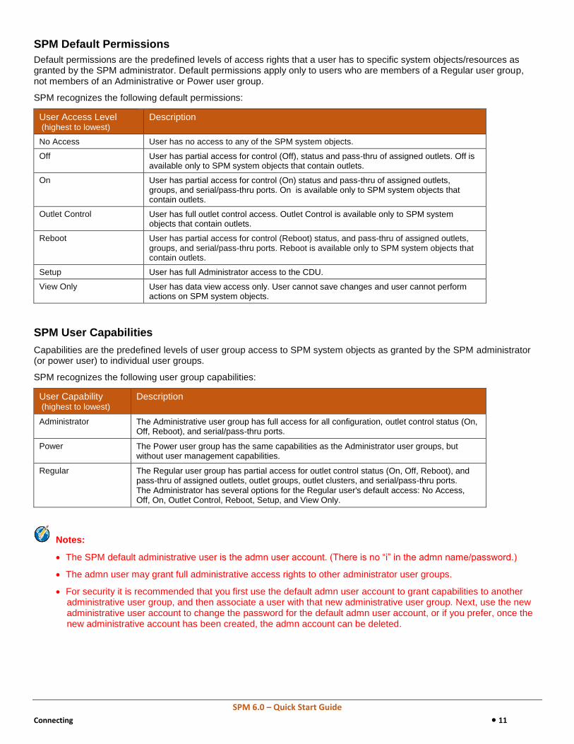
SPM Default Permissions
Default permissions are the predefined levels of access rights that a user has to specific system objects/resources as granted by the SPM administrator. Default permissions apply only to users who are members of a Regular user group, not members of an Administrative or Power user group.
SPM recognizes the following default permissions:
User Access Level (highest to lowest)
Description
No Access User has no access to any of the SPM system objects.
Off User has partial access for control (Off), status and pass-thru of assigned outlets. Off is available only to SPM system objects that contain outlets.
On User has partial access for control (On) status and pass-thru of assigned outlets, groups, and serial/pass-thru ports. On is available only to SPM system objects that contain outlets.
Outlet Control User has full outlet control access. Outlet Control is available only to SPM system objects that contain outlets.
Reboot User has partial access for control (Reboot) status, and pass-thru of assigned outlets, groups, and serial/pass-thru ports. Reboot is available only to SPM system objects that contain outlets.
Setup User has full Administrator access to the CDU.
View Only User has data view access only. User cannot save changes and user cannot perform actions on SPM system objects.
SPM User Capabilities
Capabilities are the predefined levels of user group access to SPM system objects as granted by the SPM administrator (or power user) to individual user groups.
SPM recognizes the following user group capabilities:
User Capability (highest to lowest)
Description
Administrator The Administrative user group has full access for all configuration, outlet control status (On, Off, Reboot), and serial/pass-thru ports.
Power The Power user group has the same capabilities as the Administrator user groups, but without user management capabilities.
Regular The Regular user group has partial access for outlet control status (On, Off, Reboot), and pass-thru of assigned outlets, outlet groups, outlet clusters, and serial/pass-thru ports. The Administrator has several options for the Regular user's default access: No Access, Off, On, Outlet Control, Reboot, Setup, and View Only.
Notes:
The SPM default administrative user is the admn user account. (There is no “i” in the admn name/password.)
The admn user may grant full administrative access rights to other administrator user groups.
For security it is recommended that you first use the default admn user account to grant capabilities to another administrative user group, and then associate a user with that new administrative user group. Next, use the new administrative user account to change the password for the default admn user account, or if you prefer, once the new administrative account has been created, the admn account can be deleted.

SPM 6.0 – Quick Start Guide
Connecting 12
Backup Files
The Backup Files option is a list populated by every immediate or task-scheduled backup of SPM. Once a backup file is displayed in the list (as shown below), the file can be downloaded to the local or network drives of your choice. If ever needed at a later time, the SPM system can be restored from one of the saved backup files.
Support packs for troubleshooting purposes will also be saved in Backup Files for easy downloading.
Admin Setup > Backup Files
Best Practices: Backup Files
If using either one of the SPM server appliances (APP or APPR) or a small-scale VMware system, it is important to regularly download the backup – or otherwise configure a mount point – to allow for rebuild of the SPM system in cases of total hardware failure.
Before every SPM upgrade, manually trigger a backup to run and then download it from the SPM.

SPM 6.0 – Quick Start Guide
Configuring PDUs 13
Chapter 3: Configuring PDUs
This chapter covers SPM’s regular sampling, or polling, of operational status and measurement values from networked devices, and presents how PDUs are configured – individually in SPM, and also by using the SNAP tool for mass PDU parameter updates.
First, for SPM to communicate with a device and report its dynamic data, the device must be discovered by SPM in the network.
Device Discovery
The Device Discovery feature defines the parameters to add (discover) a device to the network, allowing specific PDUs to be recognized by SPM for communication through SPM and inclusion in the SPM system.
You can discover a single device or a range of devices, and you have the choice to run the discovery immediately or hold the discovery to be run later. You can also discover devices manually, or even set up a discovery to be run on a schedule using the Scheduled Tasks option.
SPM Setup > Device Discovery
Best Practices: Device Discovery
Server Technology PDUs have a default SNMP setting of v2c enabled, get community of “public”, and set community as blank. Within the new device discovery, the SNMP settings can be edited through SNAP. At a minimum, the set community should be configured this way.
If installing SPM early in the PDU deployment process, it is especially valuable to set up the discovery as a scheduled task to begin polling data from PDUs as soon as possible.

SPM 6.0 – Quick Start Guide
Configuring PDUs 14
Cabinet Distribution Units (CDUs)
The CDUs option allows the management of cabinet/rack PDUs, including PRO2, as well as devices from many other equipment manufacturers.
In addition, other user-defined networked devices can be managed via the optional, key-activated feature Custom Device Templates.
Configuration of a PDU includes the setting of values for all device areas, such as environment, infeeds, outlets, thresholds, predictive power data, SNMP parameters, and the setup of SNAP templates to configure firmware parameters.
Device Selection > CDUs
Best Practices: Cabinet Distribution Units (CDUs)
The name “CDU” is a catch-all term that refers to devices on a single IP address. This could be one to four Server Technology PDUs, a PDU from another manufacturer, or a device built within SPM using the Custom Device Templates tool. Keep the “CDU” terminology in mind as you proceed to the Alerting chapter in this guide where PDU measurement-based areas are presented.

SPM 6.0 – Quick Start Guide
Configuring PDUs 15
Configuring CDUs
Many parameters are available in SPM for CDU configuration, including setting the high/low critical/warning power (W) thresholds of the CDU, the power capacity (VA), and predictive power alarms. The configuration of branch, cord, line outlet, phase, and sensor is covered in the Alerting chapter of this guide.
In addition, you can specify parameters for a CDU Trend report, edit the CDU’s name, and determine which cabinet or zone will be the CDU’s parent device.
Configuration values can be applied to an individual CDU or to multiple selected CDUs at one time.
Device Selection > CDUs > Configure Thresholds: CDUs
Best Practices: Configuring CDUs
A common installation will have a master and an expansion PDU per cabinet for power redundancy. This is identified by SPM as one single CDU, for which the overall threshold is equivalent to the cabinet overall threshold. At this level, setting alerts becomes unnecessary.
Remember that thresholds need to be set as truly desired for alerting. If the cabinet has two master PDUs, power thresholds can be set here at Configuring CDUs to allow for altering when one power feed is lost.
Always set the names of CDUs and other system components with consideration for how those names should look for reporting and alerting purposes. For example, the CDU name could be changed to reflect the location and cabinet in which the CDU is installed.

SPM 6.0 – Quick Start Guide
Configuring PDUs 16
PDU Settings
From the drop-down menu shown in the previous “Configure Thresholds: CDUs” screen example, select a configuration setup type and the related configuration window will be displayed.
PDU settings can be changed as follows:
This configuration menu option … … allows editing for these PDU parameters:
Branch CDU name
CDU CDU name, low/high critical/warning power (W), power capacity (VA), and specify
predictive power alarms.
Input Cord CDU name, input cord active power hysteresis (W), input cord apparent power
hysteresis (W), input cord power factor hysteresis, and out-of-balance hysteresis (%).
Line CDU name, and line current hysteresis (A).
Outlet CDU name, sequence interval(s), reboot delay(s), outlet current hysteresis (A), outlet
active power hysteresis (W), and outlet power factor hysteresis (numeric).
Phase Phase voltage hysteresis (V) and phase power factor hysteresis (numeric).
Sensor Temperature hysteresis (numeric) and humidity hysteresis (numeric).

SPM 6.0 – Quick Start Guide
Configuring PDUs 17
Overview of SNAP
The SNAP option allows the administrator (and power user) to quickly push the numerous and latest values of PDU parameters to discovered network devices that are in normal operating status and communicating with SPM.
Note: SNAP is available only for Server Technology PDUs with firmware version 6.1 or later.
SNAP works directly from within the SPM user interface, allowing a SNAP template to be created with user-customized parameter values.
These values can then be applied to a single PDU or multiple PDUs, or applied to all PDUs within a named SPM parent-level cabinet, location, or zone.
SPM Setup > SNAP Setup

SPM 6.0 – Quick Start Guide
Configuring PDUs 18
About the SNAP Template
A SNAP template is SPM’s mirror-image of a large subset of the overall PDU firmware parameters. These are the same PDU parameters configured using the firmware's Web Interface or Command Line Interface, available through SNAP for editing directly in the SPM GUI.
SPM Setup > SNAP Setup
When network PDUs are discovered by SPM, the SNAP tab shows the parameter values exactly as they have been set in the PDU itself.
All necessary PDU parameters are provided by default in SPM in the SNAP default template. You can then edit parameters in the default template, which will be used as initial settings for the creation of new templates.
You can also create and use a SNAP template based on existing PDUs. Prior to mass configuration updates, you have the option to protect your settings on designated units from the mass update.
By applying the SNAP template to a cabinet, location, or zone, you will mass-apply the updates to all PDUs within those parent-level objects.
Best Practices: SNAP
Take the time to set up the SNAP default template as desired to cover the most standard configurations for your PDUs.
SNAP is a powerful tool! Always double-check the parameters being configured by the SNAP template before clicking the Apply button.
Set up an “SNMP” template for SNAP execution upon discovery of new PDUs. Adding the set community for SNMPv2c allows for changing names and thresholds within the PDUs. Alternatively, set up SNMPv3 in this manner for more secure communication.

SPM 6.0 – Quick Start Guide
Visualizing 19
Chapter 4: Visualizing
This chapter covers how you view the PDUs within named cabinets and locations, monitor numerous operational metrics, and drill-down to specific device details that assist in effective power management.
Cabinets
The Cabinets option allows the management of user-defined cabinets that contain PDUs and other devices. Cabinet configuration allows the setting of cabinet thresholds for power, capacity, and load measurements, as well as viewing operational information and generating trend reports. The Cabinets application also provides options for power modifier and cabinet redundancy.
Device Selection > Cabinets
Power Modifier
The value you enter for Power Modifier is the known unmonitored power usage from your own history of device data. SPM tracks the value (if any) in the Power Modifier field (the static value in Watts that you enter for a cabinet), and then lets you view power usage for all units in that cabinet as part of the total power displayed in the cabinet reports.
Cabinet Redundancy
The Cabinet Redundancy option makes it easy to verify the power load in a cabinet (both A and B power sides of a PDU). You can see the load against the electrical safety rating. If power is lost, the color-coded bar chart shows the power you have in the moment compared to the capacity of the cabinet and its safety rating. In the event of a power failure in either the A or B power sides of the cabinet, the dynamic and readily available graphical information assists you in keeping cabinet operations uninterrupted, and prevents tripping a breaker and losing both sides of power.
Best Practices: Cabinets
For a more detailed graphical view, create cabinets even when PDUs are not yet installed.
Cabinet thresholds for power usage are often more understandable than the variable “CDU” total power thresholds. Use the 80% rule for warning level and 90% for critical level.

SPM 6.0 – Quick Start Guide
Visualizing 20
Locations
The Locations option allows the graphical management of network devices on a user-selected image file, such as a building, state map, city, room, floor, or any image that represents the data center layout.
Locations are the background in the Views application upon which the administrator builds a graphic representation of the facility using color-coded device icons for at-a-glance graphical monitoring of network operations.
The Locations window displays current status and other dynamic operational parameters for each named location.
Device Selection > Locations

SPM 6.0 – Quick Start Guide
Visualizing 21
Configuring Locations
Numerous location parameters are available for configuration. You can set values for a location’s critical/warning low/high power (W), the CO2 and cost per kWh, monetary symbol, maximum/allowed capacity (VA), total facility power, and the setting of predictive alarms.
Device Selection > Locations > Configure Thresholds: Locations
Best Practices: Locations
Keep the background images simple. Too many details like text or extraneous outlines make for cluttered views of status screens.
Create only necessary levels. For example, if your organization has multiple sites that reside entirely within one city, make that city the top level location.
Use the shortcut buttons “X”, “Y”, “W”, and “H” to position or size all cabinet icons within the map.
Setting thresholds at the Location level allows for predictive trending.
Make early decisions on CO2 and Cost to ensure the accumulated data is relevant when you need it.
SPM 6.0 – Quick Start Guide
Alerting 22
Chapter 5: Alerting
This chapter covers the alerting features SPM provides for monitoring and configuring the measurement-based areas of the PDU. For example, you can receive alerts for breaker or fuse errors per branch, for notification of the operational status of environmental monitors and various sensors, as well as for overload on power (device) lines.
Several functional areas of SPM work in conjunction to provide a comprehensive alerting system: Branches, Contacts, Device Lines, Environmental Monitors (EMCUs), Input Cords, Over-Current Protectors (OCPs), Outlets, Phases, and Sensors. These features are dependent upon the specific model of PDU being monitored. Not all features are available on all models.
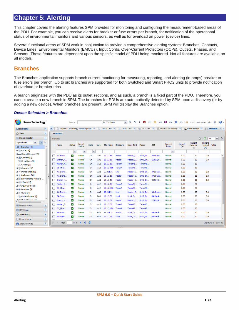
Branches
The Branches application supports branch current monitoring for measuring, reporting, and alerting (in amps) breaker or fuse errors per branch. Up to six branches are supported for both Switched and Smart PRO2 units to provide notification of overload or breaker trips.
A branch originates with the PDU as its outlet sections, and as such, a branch is a fixed part of the PDU. Therefore, you cannot create a new branch in SPM. The branches for PDUs are automatically detected by SPM upon a discovery (or by adding a new device). When branches are present, SPM will display the Branches option.
Device Selection > Branches

SPM 6.0 – Quick Start Guide
Alerting 23
Configuring Branches
To configure a branch, you can set multiple load levels for low/high warning/critical values (A) for branch current thresholds, plus the branch name can be edited.
Branch thresholds are automatically affected by certain changes to the OCP current capacity, based on the North American 80% rule.
Note: For certain CDUs running firmware version 7.0 or earlier, internally defined “infeeds” are mapped to SPM into the Branches option.
Device Selection > Branches > Configure Thresholds: Branches
Best Practices: Branches
Leave the capacity of various items as they are by default. For example, the OCP current capacity of 20A based on the installed breaker or fuse.
Only reduce the alert high threshold levels after understanding that there are no “normal” conditions that exceed that value. In other words, do not create nuisance alarms.
Wait to set any alert low threshold levels until after there is sufficient data in the system to help understand what is “normal”.
Use the Set Column Value option for mass configuration.

SPM 6.0 – Quick Start Guide
Alerting 24
Contacts
The Contacts option displays status of the environmental monitor and operational information when monitoring contact closure sensors. A discovered PDU, or an environmental monitor on the PDU, must have a connected contact closure or the Contacts option will not display in SPM.
Device Selection > Contacts
Device Selection > Contacts > Configure Thresholds: Contacts
The only contact parameter that can be edited is the contact name.
SPM 6.0 – Quick Start Guide
Alerting 25
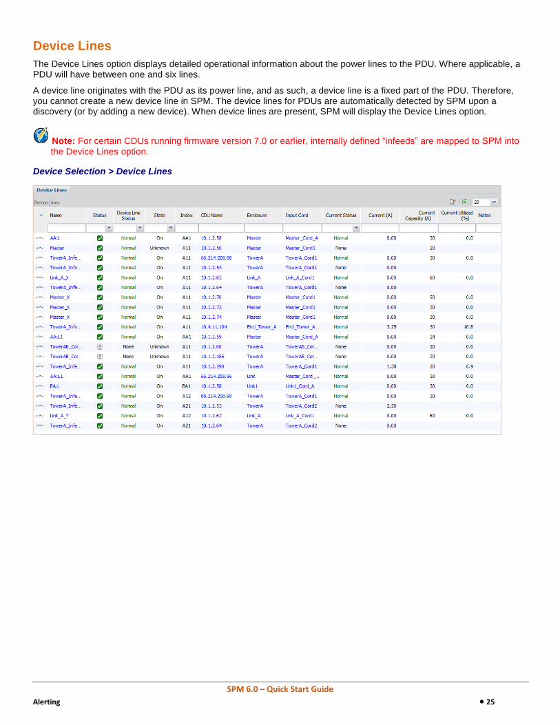
Device Lines
The Device Lines option displays detailed operational information about the power lines to the PDU. Where applicable, a PDU will have between one and six lines.
A device line originates with the PDU as its power line, and as such, a device line is a fixed part of the PDU. Therefore, you cannot create a new device line in SPM. The device lines for PDUs are automatically detected by SPM upon a discovery (or by adding a new device). When device lines are present, SPM will display the Device Lines option.
Note: For certain CDUs running firmware version 7.0 or earlier, internally defined “infeeds” are mapped to SPM into the Device Lines option.
Device Selection > Device Lines

SPM 6.0 – Quick Start Guide
Alerting 26
Configuring Device Lines
If a PDU’s device lines are discovered by SPM, you can configure critical/warning low/high current (A), and change the name of the device line.
Configuration values can be applied to an individual device line or to multiple selected device lines at one time.
Device Selection > Contacts > Configure Thresholds: Device Lines
From the Column menu shown in the example above, select a device line configuration area, and the related configuration window displays for editing.
Best Practices: Device Lines
The Device Line alert is one of the most important alerts for the management of uptime in the data center. The default setting follows the North American 80% rule, such that a “30A” circuit alerts at 24A on any line. When installing a pair of PDUs for power redundancy, set the alert level to 40% to provide the most conservative uptime protection.
To provide clear understanding of alerts or reports, name the device lines based on any existing upstream circuit name or the cabinet name.

SPM 6.0 – Quick Start Guide
Alerting 27
Environmental Monitors
The Environmental Monitors option displays status and operational information about the PDU’s embedded environmental monitor or attached EMCU, which can be useful for managing network assets.
Included are metrics for monitoring water and analog-to-digital (ADC) sensors – if these sensors are connected to the EMCU. Water sensors will have either Normal or Alarm status; they have no other states or value ranges.
Device Selection > Environmental Monitors

SPM 6.0 – Quick Start Guide
Alerting 28
Configuring Environmental Monitors
If an ADC sensor or water sensor is connected to the EMCU, you will be able to configure low/high critical/warning ADC readings and hysteresis, as well as edit the ADC name. You can also edit ADC and water sensor name.
Device Selection > Environmental Monitors > Configure Thresholds: Environmental Monitors
From the Column menu shown in the example above, select a sensor configuration area, and the related configuration window displays for editing.

SPM 6.0 – Quick Start Guide
Alerting 29
Input Cords
The Input Cord option displays hardware specifications and the latest infeed status and operational metrics for all cords in the SPM system.
Included are several power measurements for power capacity (VA), cord apparent power (VA), power factor (if present), and cord 3-phase out-of-balance level (%).
Device lines and phases in the PDU are part of the input cord itself.
Note: The inlet type, frequency, power capacity, and energy rating of the cord were determined for the PRO2 product at factory assembly and cannot be user-edited.
Device Selection > Input Cords
SPM 6.0 – Quick Start Guide
Alerting 30
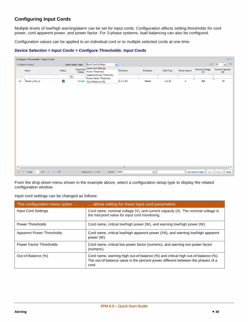
Configuring Input Cords
Multiple levels of low/high warning/alarm can be set for input cords. Configuration affects setting thresholds for cord power, cord apparent power, and power factor. For 3-phase systems, load balancing can also be configured.
Configuration values can be applied to an individual cord or to multiple selected cords at one time.
Device Selection > Input Cords > Configure Thresholds: Input Cords
From the drop-down menu shown in the example above, select a configuration setup type to display the related configuration window.
Input cord settings can be changed as follows:
This configuration menu option … … allows editing for these input cord parameters:
Input Cord Settings Cord name, nominal voltage (V), and current capacity (A). The nominal voltage is the mid-point value for input cord monitoring.
Power Thresholds Cord name, critical low/high power (W), and warning low/high power (W).
Apparent Power Thresholds
Cord name, critical low/high apparent power (VA), and warning low/high apparent
power (W).
Power Factor Thresholds Cord name, critical low power factor (numeric), and warning low power factor
(numeric).
Out-of-Balance (%)
Cord name, warning high out-of-balance (%) and critical high out-of-balance (%).
The out-of-balance value is the percent power different between the phases of a
cord.

SPM 6.0 – Quick Start Guide
Alerting 31
Best Practices: Input Cords
Maintain default alert levels until after sufficient trending can be recorded to determine what is considered “normal” behavior.
Name the input cords based on an existing upstream circuit name or the cabinet name to provide clear understanding of alerts or reports.
SPM 6.0 – Quick Start Guide
Alerting 32
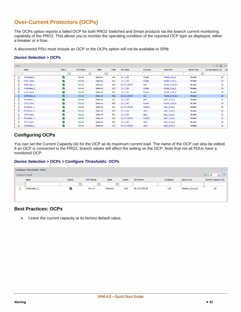
Over-Current Protectors (OCPs)
The OCPs option reports a failed OCP for both PRO2 Switched and Smart products via the branch current monitoring capability of the PRO2. This allows you to monitor the operating condition of the reported OCP type as displayed, either a breaker or a fuse.
A discovered PDU must include an OCP or the OCPs option will not be available in SPM.
Device Selection > OCPs
Configuring OCPs
You can set the Current Capacity (A) for the OCP as its maximum current load. The name of the OCP can also be edited. If an OCP is connected to the PRO2, branch values will affect the setting on the OCP. Note that not all PDUs have a monitored OCP.
Device Selection > OCPs > Configure Thresholds: OCPs
Best Practices: OCPs
Leave the current capacity at its factory default value.

SPM 6.0 – Quick Start Guide
Alerting 33
Outlets
Depending on specific features of certain PDUs; for example, Switching or POPS, the Outlets option displays all outlets for discovered PDUs in SPM and provides operational status for outlet power monitoring, the issuing of outlet command control (On/Off/Reboot), and the setting of outlet threshold values, including user group permissions for the outlets.
Also provided is a fast drill-down (by clicking a specific outlet name in the Outlets list) to show additional, detailed operational data.
Device Selection > Outlets
The operating status of all discovered outlets should be Normal. If necessary, drill-down to view operational details for an outlet in a warning or critical condition.
Note that the outlet’s identification number (Index) and socket type are determined at factory assembly and cannot be user-configured.

SPM 6.0 – Quick Start Guide
Alerting 34
Configuring Outlets
To configure an outlet, you can identify the outlet by name and also set values for post-on delay, wake up state, and user voltage. In addition, you can set a threshold range for critical low/high outlet current (A) and specify parameters for an outlet Trend report.
To track network devices for asset management, an asset tag and URL can be provided for specific outlets. Configuration values can be applied to an individual outlet or to multiple selected outlets at one time.
Device Selection > Outlets > Configure Thresholds: Outlets
Best Practices: Outlets
There is no need to change the names of outlets. A better practice would be to create cabinet devices, as the most current IT equipment is designed with multiple power supplies.
Maintain default alert levels until after sufficient trending can be recorded to determine what is considered “normal” behavior.

SPM 6.0 – Quick Start Guide
Alerting 35
Phases
The Phases option provides data for each phase of a multi-phase cord, including phase status, phase voltage, and power factor.
A phase originates with the PDU as its output circuit, and as such, a phase is a fixed part of the PDU. Therefore, ou cannot create a new phase in SPM. The phases for PDUs are automatically detected by SPM upon a discovery, or by adding a new device. When phases are present, SPM will display the Phases option.
Note: For certain CDUs running firmware version 7.0 or earlier, internally defined “infeeds” are mapped to SPM into the Phases option.
Device Selection > Phases
Configuring Phases
To configure a phase, you can edit the name of the phase and determine a threshold range for critical low/high phase voltage and for critical low/warning power factor. Phase voltage minimum and maximum values will vary by product. Configuration values can be applied to an individual phase or to multiple selected phases at one time.
Best Practices:
Name the phases based on any existing upstream circuit name or the cabinet name to provide clear understanding of alerts or reports.
Maintain default alert levels until after sufficient trending can be recorded to determine what is considered “normal” behavior.

SPM 6.0 – Quick Start Guide
Alerting 36
Device Selection > Phases > Configure Thresholds: Phases

SPM 6.0 – Quick Start Guide
Alerting 37
Sensors
The Sensors option provides a quick view of the current operating status of environmental sensors. For the Sensors option to display in SPM, a discovered PDU or environmental monitor must be connected to a sensor.
Device Selection > Sensors

SPM 6.0 – Quick Start Guide
Alerting 38
Configuring Sensors
To configure a sensor, you can set system-wide low/high temperature/humidity thresholds, choose a predictive temperature warning alarm, and edit the name of a sensor.
Configuration values can be applied to an individual sensor or to multiple selected sensors at one time.
Device Selection > Sensors > Configure Thresholds: Sensors
Best Practices: Sensors
Name the sensors based on the cabinet name and position within that cabinet to provide clear understanding of alerts or reports.
Do not set overly tight alert levels until after sufficient trending can be recorded to determine what is considered “normal” behavior.

SPM 6.0 – Quick Start Guide
Aggregating 39
Chapter 6: Aggregating
This chapter covers the aggregation of data that SPM offers to allow you to name a custom collection of related system objects and then monitor, report, control, and configure all objects in that collection at one time. SPM’s capability to group objects for administration is a fast and flexible way to arrange and manage areas that are unique to your data center.
Cabinet Devices
The Cabinet Devices option allows the administrator to name a collection of cabinet-contained devices types within a specific cabinet. The collection of cabinet devices is an accurate and easy way for a cabinet to monitor device-level power and environmental data, especially for devices that typically cannot be measured easily.
By using cabinet devices, power management is placed directly within the equipment rack, which assists in data center efficiency, cost savings, and capacity planning.
You can run reports on cabinet devices to show the U space used, cabinet redundancy, and inventory of cabinet devices.
Device Selection > Cabinet Devices
Cabinet Device Objects
SPM allows the following object types to be collected and monitored within a cabinet device. These objects include servers, power meters, environmental units, and other device types:
Blade Server Environmental Unit KVM Network Storage Server
Power Meter Security System Server Serial Console UPS
SPM 6.0 – Quick Start Guide
Aggregating 40
Best Practices: Cabinet Device Objects
With Switchable-PDU outlets, it is important to be sure of what your are turning on or off. Take the time to catalog and configure Cabinet Devices at the outset and at the time of equipment deployment.
Use POPS outlet measurement PDUs to provide guidance for future equipment decisions.

SPM 6.0 – Quick Start Guide
Aggregating 41
Circuits
The Circuit option allows you to collect power lines across the data center and name your line collection as a unique circuit. Using this application allows you to define the physical infrastructure of power systems that feed your PDUs, regardless of which breakers are targeted by the collected lines. SPM refers to the power lines within your defined circuit collection as "circuit lines".
When using the Circuits option, you can easily determine an out-of-balance condition in a 3-phase system.
Device Selection > Circuits
Circuit Lines
The power lines within your defined circuit are referred to as “circuit lines”, and these lines only display in the Circuit Lines window if you first created a circuit and then included named power lines in the circuit.
Device Selection > Circuits > Circuit Lines
Best Practices: Circuits
With Switchable-PDU outlets, it is important to be sure of what your are turning on or off. Take the time to catalog and configure cabinet devices at the outset and also when equipment is deployed.
Set Circuit Line current thresholds based on the ratings of upstream circuit devices, such as RPP or floor PDU.

SPM 6.0 – Quick Start Guide
Aggregating 42
Zones
The Zones option offers an additional way to group PDUs or cabinets (virtually, in a named zone) for viewing and trending, regardless of the physical locations of the devices.
Note: Only PDUs and cabinets can be grouped in a zone. However, PDUs and cabinets cannot be mixed together in the same zone.
Device Selection > Zones
Best Practices: Zones
Create zones for common physical location, common functional types, common project ownership, configuration needs, or any other commonality.
Create zones early for best future data analysis.

SPM 6.0 – Quick Start Guide
Analyzing 43
Chapter 7: Analyzing
This chapter covers the reports, trends, and task scheduler that SPM provides for the analysis of power metrics as well as the dynamic operating condition of networked devices.
Reports
The Reports option provides numerous types of reports you can choose for power, environmental data, and more, with user-specified parameters to customize each report, such as the reporting time frame and any object grouping preferences. All reports allow the grouping by a named zone, and you have the option to share any report with other SPM users.
Reports show data collected from PDU readings; therefore, data must be available in the device for the report you want to run or the report will be blank.
Reports Menu > Reports
Best Practices: Reports
Create and run the Inventory report to access characteristics of discovered PDUs, including the firmware version.
Create and run the Cabinet Redundancy report to check for any initial risks against uptime.
Create the Energy Consumed (by Month) report to begin efficiency and cost analysis over time.
Share your reports, rather than having other users create duplicates.
SPM 6.0 – Quick Start Guide
Analyzing 44
Trends
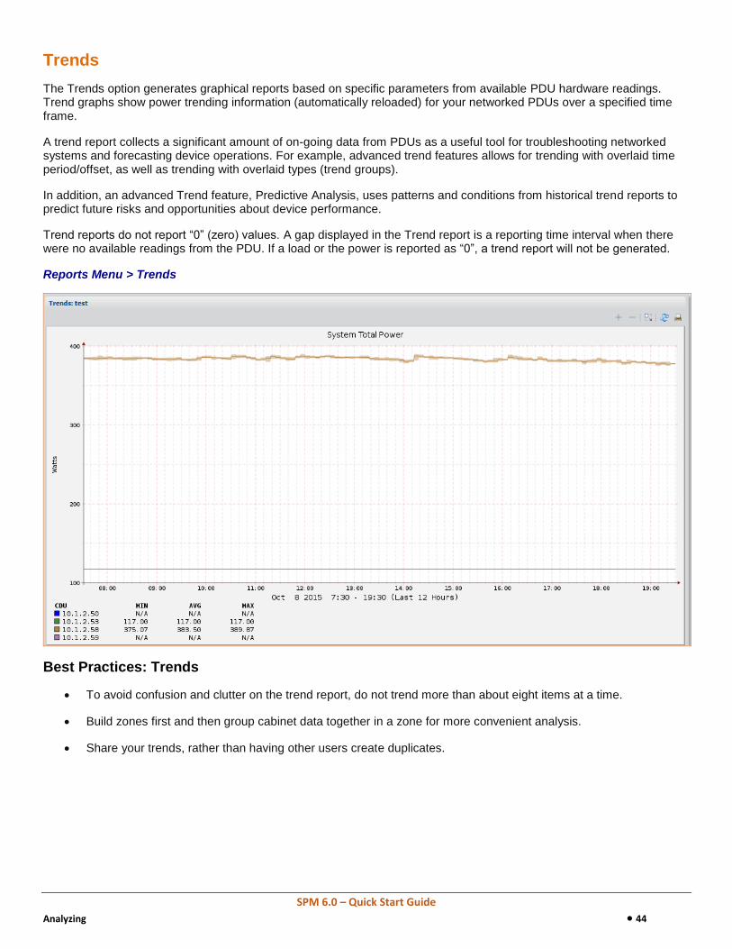
The Trends option generates graphical reports based on specific parameters from available PDU hardware readings. Trend graphs show power trending information (automatically reloaded) for your networked PDUs over a specified time frame.
A trend report collects a significant amount of on-going data from PDUs as a useful tool for troubleshooting networked systems and forecasting device operations. For example, advanced trend features allows for trending with overlaid time period/offset, as well as trending with overlaid types (trend groups).
In addition, an advanced Trend feature, Predictive Analysis, uses patterns and conditions from historical trend reports to predict future risks and opportunities about device performance.
Trend reports do not report “0” (zero) values. A gap displayed in the Trend report is a reporting time interval when there were no available readings from the PDU. If a load or the power is reported as “0”, a trend report will not be generated.
Reports Menu > Trends
Best Practices: Trends
To avoid confusion and clutter on the trend report, do not trend more than about eight items at a time.
Build zones first and then group cabinet data together in a zone for more convenient analysis.
Share your trends, rather than having other users create duplicates.

SPM 6.0 – Quick Start Guide
Analyzing 45
Scheduling
The Schedule Tasks option defines and schedules certain SPM system events to run automatically on a future date, or to run on a recurring basis, as user-specified.
An example of a scheduled task would be to set up the outlet command action Off, On, or Reboot to be issued on one or more outlets – or on an outlet group, outlet cluster, or cabinet device – to automatically run at the same time each week for the specified outlets.
SPM Setup > Scheduled Tasks
Available Scheduled Tasks
SPM allows the following tasks to be scheduled, based on your defined run parameters:
Backup: Back up of the SPM system
Cabinet Device: Issue outlet action Off, On, or Reboot to specified outlets collected in a cabinet device,
Database Maintenance: Run selective SPM functions in database maintenance.
Database Full Maintenance: Run all SPM functions in database maintenance.
Device Discovery: Discover specified network devices.
Email Report: Run one of the user reports at a designated time.
Email Trend: Run one of the graphical trend reports at a designated time.
Outlet Actions: Issue outlet action Off, On, or Reboot to selected outlets.
Outlet Cluster: Issue outlet action Off, On, or Reboot to specified outlet clusters.
Outlet Group: Issue outlet action Off, On, or Reboot to specified outlet groups.

SPM 6.0 – Quick Start Guide
Analyzing 46
Best Practices: Scheduling
Create a task to email Cabinet Redundancy and Energy (by Month) to yourself a the first of each month.
Leave the database maintenance tasks as is, but set the backup task as desired. The database backup includes both data collection and all system setup work.

SPM 6.0 – Quick Start Guide
Tying It All Together 47
Chapter 8: Tying It All Together
This chapter covers how the Views option allows you to pull together a customized and graphical layout of the key SPM areas presented in this guide, as well as many other SPM functions for monitoring device metrics and managing the equipment network.
Views
The Views application lets you choose the type of SPM device data you want to see and places that data in a graphical workspace according to your own layout preferences.
Views is the go-to place in SPM for a fast, color-coded, and graphical overview of device operational information, just as you want to monitor it. Each user can create a custom view that SPM saves and displays for the user’s login.
Also provided is the SPM Wizard View to get you up and running fast with an SPM device discovery that automatically populates a new View page with a few standard device information panels.
In addition, when you create several different views pages, you can run a slideshow of all views for quick monitoring.
SPM > Views > [user-named view]
SPM 6.0 – Quick Start Guide
Tying It All Together 48
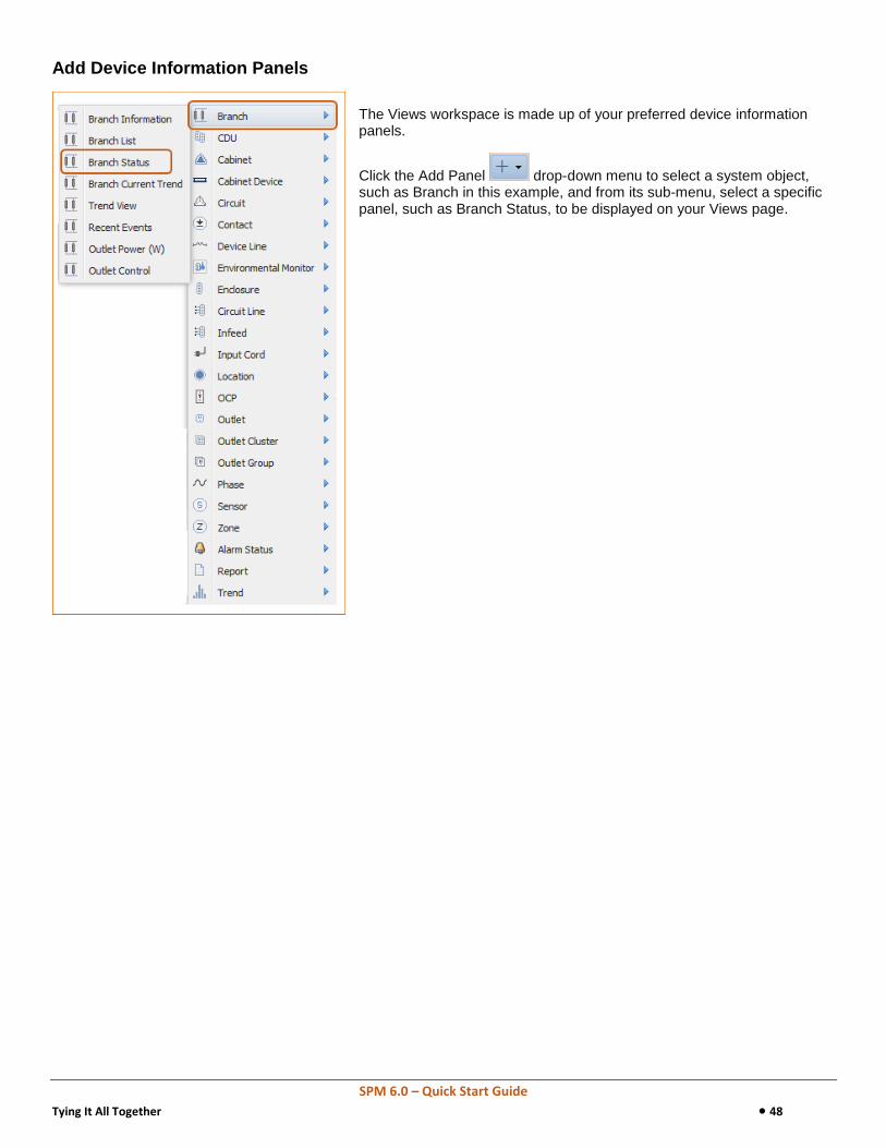
Add Device Information Panels
The Views workspace is made up of your preferred device information panels.
Click the Add Panel drop-down menu to select a system object, such as Branch in this example, and from its sub-menu, select a specific panel, such as Branch Status, to be displayed on your Views page.

SPM 6.0 – Quick Start Guide
Tying It All Together 49
Choose a Workspace Layout
The size and position of device panels on the Views workspace can be customized for your user login.
Click the Set Layout drop-down menu to select the preferred arrangement for panel size and position on your Views page.
Best Practices: Views
Share your views, rather than having other users create duplicates.
Keep the views to just a few panels and create multiple views for use in the Views Slideshow feature.
Consider creating views of one-panel-per-view for slideshows run on NOC screens.
SPM 6.0 – Quick Start Guide
Special Features 50
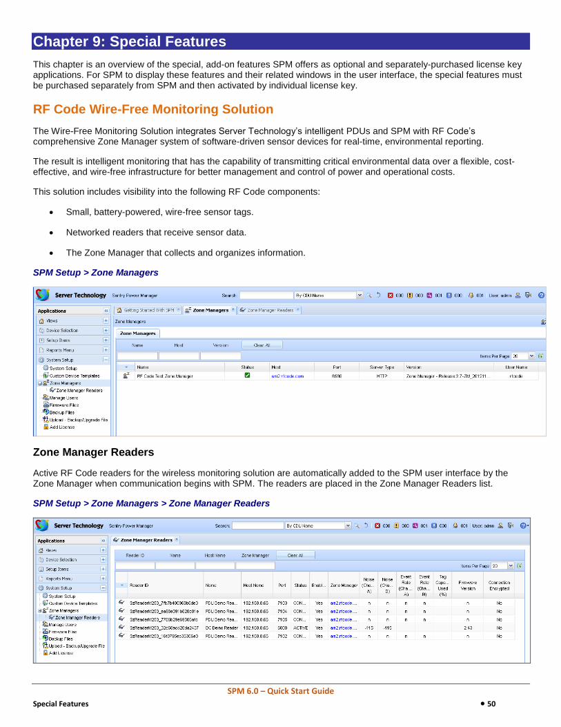
Chapter 9: Special Features
This chapter is an overview of the special, add-on features SPM offers as optional and separately-purchased license key applications. For SPM to display these features and their related windows in the user interface, the special features must be purchased separately from SPM and then activated by individual license key.
RF Code Wire-Free Monitoring Solution
The Wire-Free Monitoring Solution integrates Server Technology’s intelligent PDUs and SPM with RF Code’s comprehensive Zone Manager system of software-driven sensor devices for real-time, environmental reporting.
The result is intelligent monitoring that has the capability of transmitting critical environmental data over a flexible, cost-effective, and wire-free infrastructure for better management and control of power and operational costs.
This solution includes visibility into the following RF Code components:
Small, battery-powered, wire-free sensor tags.
Networked readers that receive sensor data.
The Zone Manager that collects and organizes information.
SPM Setup > Zone Managers
Zone Manager Readers
Active RF Code readers for the wireless monitoring solution are automatically added to the SPM user interface by the Zone Manager when communication begins with SPM. The readers are placed in the Zone Manager Readers list.
SPM Setup > Zone Managers > Zone Manager Readers

SPM 6.0 – Quick Start Guide
Special Features 51
Custom Device Templates
The Custom Device Templates feature allows communication, tracking, and reporting for any SNMP-enabled device within SPM. This feature has the capability of tracking data center power from within SPM using measurements from an unsupported device, like a UPS. The benefit of using Custom Device Templates is the convenience of adding individual infeeds and outlets directly to SPM one at a time, as needed.
A new custom template can be created and configured with template values for numerous device attributes. When adding the new device to SPM, you apply the specific attributes to the new device. This allows the custom device values to be tracked and monitored in several places throughout the SPM interface.
SPM Setup > Custom Device Templates
Supported Values
SPM supports three groups of values so you can apply a value that is unique to your custom device:
Custom Device Value Group Applied Attributes
Whole Device Level Device model, version, serial number, power type, total power (watts), manufacturer custom text (any string value you want to track), and a maximum of three custom numeric fields (any numeric value you want to track).
Infeed Index, name, current (amps), power (watts), voltage (volts), apparent power (volt-amps), and power factor (%).
Outlet Index, name, current (amps), power (watts), voltage (volts), apparent power (volt-amps), and power factor (%).
Best Practices: Custom Device Templates
To confirm your SNMP OID configuration is correct, after the configuration, verify that the data being polled by SPM matches the device interface data.

SPM 6.0 – Quick Start Guide
Special Features 52
Hub and Node
The Hub and Node feature allows multiple SPM systems to be connected to each other. One of the systems in the connection (the hub) gathers and displays information about the other systems (the nodes). As the hub monitors key information for each node in the connection, each node continues to perform on its own as a fully functional and complete SPM system.
Note: The Hub and Node feature is not designed for redundancy or as a fail-over mode for multiple SPM systems.
When the Hub and Node feature is activated, the SPM Nodes list shows all connected SPM systems. The hub is listed with all of its connected nodes, and the nodes are listed with their hub, each hub and node shown as a separate item.
SPM Setup > SPM Nodes
System Definitions
These terms describe the type of Hub and Node systems available in SPM:
Hub: An SPM system that can manage other SPM systems, called nodes.
Node: An SPM system that be managed by another single SPM system, called the hub.
Partial Sync: The limited hub operation that only collects frequently-updated PDU values from the node. These partial sync values can include alarms, power, load, and energy.
Standalone: An SPM system that cannot be used as a hub or a node, or be managed by a hub. To allow a standalone SPM system to become a hub (or a node), a separate license key must be applied to the standalone SPM system.
Sync/Full Sync: The hub operation that collects PDU information from the node.
Best Practices: Hub and Node
Hub and Node is best used when:
Multiple data centers need to be viewed under a single-pane-of-glass.
Latency between sites is excessive.
Extreme numbers of PDUs need to be monitored.

SPM 6.0 – Quick Start Guide
Special Features 53
Obtain a Feature License Key
SPM offers special features as optional and separately-purchased applications. Each feature is activated by an individual license key. To purchase a license key for one or more of SM features, contact your Server Technology representative at:
1-800-835-1515 (domestic), ++0 (1) 775.284.2000 (international), or [email protected]
When activated by the key provided by Server Technology, the SPM window (shown below) at Application Help > Product License displays the Enabled status for the active feature(s).
In this example, the following Product License window highlights the RF Code Zone Manager and Custom Device Templates (Custom Template) as enabled features. Note that the enabled Standalone SPM simply means the current SPM system does not have the Hub and Node feature activated.

SPM 6.0 – Quick Start Guide
Appendix A: Product Information 54
Appendix A: Product Information
Warranty
For Server Technology warranty information, visit our website: www.servertech.com
Contact Technical Support
Experience Server Technology's FREE Technical Support
Server Technology understands that there are often questions when installing and/or using a new product. Free Technical Support is
provided from 8 a.m. to 5 p.m. PST, Monday through Friday. After-hours service is provided to ensure your requests are handled
quickly no matter what time zone or country you are located in.
Server Technology, Inc.
1040 Sandhill Drive Tel: 775.284.2000 Web: www.servertech.com
Reno, Nevada 89521 USA Fax: 775.284.2065 Email: [email protected]
Return Merchandise Authorization (RMA)
If you have a product that is not functioning properly and needs technical assistance or repair, see the Server Technology Return
Merchandise Authorization process at: www.servertech.com
