sensors, instrumentation and measurement
TRANSCRIPT

Sensors, Instrumentation and Measurement
The Drilling Systems Automation Roadmap Sensors Instrumentation and Measurements section
describes the quality and attributes of data sources needed to enable successful progression of DSA.
Table of Contents
Development Team .......................................................................................................................................... 1
Functional Description ..................................................................................................................................... 2
Performance targets ........................................................................................................................................ 3
Sensor Rules ............................................................................................................................................................... 3
Sensor Quality ............................................................................................................................................................ 4
Time Stamps............................................................................................................................................................... 4
Levels of IMS Attributes ............................................................................................................................................. 5
Current Situation ............................................................................................................................................. 7
Problem Statement .......................................................................................................................................... 9
Way Ahead .................................................................................................................................................... 12
Context Data Standards ........................................................................................................................................... 13
State Variables ......................................................................................................................................................... 14
Enhanced Sensor Capabilities .................................................................................................................................. 15
References ..................................................................................................................................................... 16
Appendix I: Systems of Interest IMS Examples................................................................................................. 17
Development Team John Macpherson: Baker Hughes, a GE Company, Leader
Eric Cayeux, IRIS now NORCE
Fred Florence, NOV now Rig Ops
Jan Jette Belange, Shell
Stephen Lai, Pason

7 of 14: Sensors Instruments and Measurement (IMS)
Version 19 05 31 Public Release Copyright © DSARoadmap.org 2019 Page 2
Robert Wylie, NOV now Xn Drilling
Aaron Eddy, Pason
Functional Description Sensors, instruments and measurement section covers the strategic development of downhole and
surface sensors, instrumentation and measurement (IMS) that support drilling systems automation.
The industry has a need to integrate the various IMS that form part of the drilling process to create
systems that deliver reliable, quality data to consumers in a timely fashion. Consumers include
reporting, monitoring, real-time modeling, advisory, analytical and control tasks.
The scope of IMS includes:
• Both open (conventional) and closed (MPD, UBD, DGD etc.) drilling systems
• Smart machines, which may be considered measurement platforms that deliver valuable measurements for DSA.
• Operational and machine system limits that define the required performance of the sensors.
• Sampling requirements, anti-aliasing, sensor resolution, accuracy and precision, system latency and time synchronization.
The challenge excludes:
• Surface or downhole machines that do not provide measurements but do represent a level of
mechanization.
• Context data, such as an Earth Model, Directional Drilling Plan, or BHA configuration are
assumed to be available for drilling systems automation.
• Algorithmic processing of data, such as depth tagging, processing, data distribution, data
aggregation, data event processing, data visualization and data security.
Systems of Interest for sensors, data and their measurements can be created from the System of
Systems architecture. These Systems of Interest are recognized because they contain families of
data that deliver subsystem functionality. Progression of data acquisition within a system or
subsystem will be more successful than partial acquisition across several subsystems because value
can be more readily delivered by the former than the latter.
Systems of interest include:
• Hoisting and Rotating (e.g., hoisting system, top drive, travelling block, power slips)
• Fluids system
o Solids control
o Fluids preparation and treatment
o Fluids pumping
• Mud Logging Surface Data Acquisition

7 of 14: Sensors Instruments and Measurement (IMS)
Version 19 05 31 Public Release Copyright © DSARoadmap.org 2019 Page 3
• Downhole Data Acquisition
o MWD Data Acquisition
o LWD Data Acquisition
• Drill string System
• BHA System
• Cementing System
• Pipe handling system
Performance targets Performance targets include sensor rules, sensor quality, time stamps and levels of IMS attributes.
Sensor Rules Sensors, Instrumentation and Measurement Systems for Drilling Systems Automation should meet
certain rules to ensure users understand how a measurement, or a set of measurements, will affect
the process being automated (Table 1).
Rule Description
1 Completeness There must be enough information to fully determine the state of the system.
2 Logic Determination
There must be all information necessary to choose the correct sensor as a function of the system state.
3 Proximity Sensors shall measure as directly and as closely as possible to the required parameters. The four types of proximity include:
a) Direct: measured directly at the desired location. b) Transposed: converted from some measurement conditions to
another. c) Derived: depends on at least two consecutive measurements. d) Estimated: depends on a series of measurements and initial
conditions.
4 Accuracy There must be enough information to assess the accuracy of the measurement. If a measurement is made remote to the desired location, there must be sufficient information to access the accuracy of the estimated measurement.
5 Conversion There must be enough information to correct the measurement. If this is physically not possible, a new sensor will be envisioned to solve the error.
6 Criticality There must be measurement redundancy for critical parameters, which means there must be different measurement paths for critical parameters and not just different sensors at the same point.
7 Availability The availability of each sensor must meet or exceed the requirement of the most demanding application for which it is used. Availability performance is a statistical specification which is defined as the

7 of 14: Sensors Instruments and Measurement (IMS)
Version 19 05 31 Public Release Copyright © DSARoadmap.org 2019 Page 4
Rule Description
probability of sensor outage vs. outage duration. Applications are classified into 1 of 4 groups based on availability requirement. These groups, from the most to least demanding are:
a) Closed-Loop Control: No humans in the control loop. a. Fast-Loops: Latency < 1 sec b. Slow-Loops: Latency > 1 sec
b) Supervisory Control: Human in the control loop. c) Diagnostics: Applications delivering visual information for a
human. d) Archival: Applications that store data for historical reference.
Table 1: Sensor Rules for DSA
When measuring a parameter, several sensors may be needed in different locations to ensure that
the measurement is continuous throughout drilling operations. For example, hookload is measured
or estimated from several independent locations, such as the deadline, top drive load pins, surface
sub, to ensure a measurement as continuous as possible during drilling, tripping and connections. To
choose the correct sensor, the system should know which hookload measurement or estimate to
use depending on the drilling operation being conducted. if string weight is required then the ideal
measurement location would be at the top of the string, below the top drive.
Sensor Quality Likewise, the sensors and measurements, including those with differing levels of proximity, must be
of a quality required for reliable systems automation (Table 2).
Term Quality Description
1 Precision Reproducibility and repeatability of the measurement. This is the precision of the digital value at the end of the measurement chain, rather than the precision of the sensor itself
2 Accuracy How close the measurement is to the real value
3 Latency Time delay between the generation of the measurement and its consumption. Latency maybe fixed, variable, or non-deterministic.
4 Calibration Calibration may be offsite, or onsite, and may affect both the gain and bias of a measurement. Systems that can be calibrated onsite may be calibrated in an automatic or semi-automatic fashion.
5 Validity If a measurement fails, there must be a diagnostic method of indicating that the reading may be invalid.
Table 2: Sensor Quality for DSA
Time Stamps All data must be time stamped for correlation, integration and output derivations. A study of three
different data aggregation systems found the single biggest source of error in the drilling data was the

7 of 14: Sensors Instruments and Measurement (IMS)
Version 19 05 31 Public Release Copyright © DSARoadmap.org 2019 Page 5
time measurement1. Computer clocks providing independent time measurements differed from 2
minutes on one system to 15 minutes on another compared with the source system. This is. A serious
issue that the drilling industry must aggressed to ensure data can be correctly compared by tile
correlation which also equates to dept correlation. IEEE 1588, standard that defines time stamping of
data, provides a solution2. This standard defines a protocol enabling precise synchronization of clocks
in measurement and control systems implemented with technologies such as network
communication, local computing and distributed objects. To achieve this required state of time
synchronization for drilling systems automation, the various systems that combine to collect data and
to control a drilling operation must be networked and the downhole system must compensate for
latency of signal transmission from surface to downhole and from downhole to surface.
Levels of IMS Attributes The degree to which an IMS meets these rules, the measures of quality, and the validity of the time
stamp, will govern the automation level of a System of Interest because higher levels of automation
require higher levels of rules adoption, quality and time stamp validity (attributes).
The Levels of Automation Taxonomy (LOAT) matrix in the Human Systems Integration section
defines the various levels anticipated in drilling systems automation through the acquire, analyze,
decide and act cycle (Figure 1). The expected growth in performance of a sensor or IMS will drive the
capability for increasing levels of automation.

7 of 14: Sensors Instruments and Measurement (IMS)
Version 19 05 31 Public Release Copyright © DSARoadmap.org 2019 Page 6
Figure 1 LOAT matrix for DSA
The levels of sensor attributes rules, quality and time stamps can be described in Table 3.
IMS Attributes Description LOAT Impact
Low Very poor application of the rules, very low quality, no time stamp correlations, questionable or sporadic calibration
Suited for manual control of the drilling process. This IMS data requires human oversight to judge reliability. The operator acquires, assesses, decides and takes action.
Limited Some application of the rules to various degrees, initial application of quality control and recognition of time stamp correlation
Suited for low level automated acquisition and analysis, WITS transmission offsite. Covers display of data and low-level alarms, such as threshold alarms.
Medium Increased application of the rules, reliable depth tracking, and common time stamping and accounting for latency. May use proprietary communications protocols.
Suited for automated acquisition and analysis (monitoring) at the wellsite or remote to it. Covers display and analysis of the data (KPI tracking) and smart alarms.
Good
Full application of the rules, good quality reliable data that meets communications standards, without
Advice level IMS, suited for supplying information to models

7 of 14: Sensors Instruments and Measurement (IMS)
Version 19 05 31 Public Release Copyright © DSARoadmap.org 2019 Page 7
IMS Attributes Description LOAT Impact
full transparency (metadata), interoperability or determinism.
and simulators which can generate open-loop advice to the driller
Excellent Full application of the rules, common standards, highest quality deterministic data, transparent and interoperable, fully functioning protocol for time stamping per IEEE 1588, known and manageable latency
Full automation capability across the LOAT (acquire, assess, decide, action) – closed loop automation.
Table 3: Sensor Attributes versus LOAT Capability
Current Situation Currently, sensors, instrumentation and measurements systems typically found on even the most
advanced deepwater drilling rigs do not meet the needs of drilling systems automation. This is not a
reflection on available technology because in almost all cases sensor technology is available to meet
most of the criteria presented in the previous section. Instead, it is a reflection of the disjointed
nature of the drilling operation having many conflicting interests at the wellsite.
The roles and responsibilities of the major drilling operation participants (operator, drilling
contractor, service company, equipment supplier, shipyard, etc.) are rarely aligned to provide the
level of data required for drilling automation. This has led to a reliance on outdated low-cost
technology and an inability to merge downhole, surface and context data in real-time, to distribute
timely data to interested consumers, to perceive the worth of good timely sensor measurement
systems and, ultimately, to; a sacrifice of performance and safety.
The current state of rig subsystems required for automation from a sensor and measurement
perspective can be described in terms of mechanization, integrated control systems, measurements,
data collection, data handling, interpretation and visualization, and security and authorization.
Mechanization
A prerequisite to automation is that the system components be mechanized to a degree that will
allow for overarching control. Most recently constructed land and offshore units have sufficient
mechanization of individual drilling machines. Various makes and models of the machines have
different levels of mechanization and different sensor technologies.
For drilling automation, the rig should have a top drive used for rotating the drillstring because
although a rig equipped only with a rotary table could possibly be used for drilling automation, it
would not be a likely candidate.
Some rig systems, such as low-pressure mud systems, have manual valves on lines to and from the
pits. These could be automated through addition of position indicators or automated valves. Newer
offshore rigs may be fitted with automation-ready valves and automated drilling fluid dosing
systems have been employed on offshore rigs. Other rig systems, such as bulk mud, cement and air
will probably require upgrading.

7 of 14: Sensors Instruments and Measurement (IMS)
Version 19 05 31 Public Release Copyright © DSARoadmap.org 2019 Page 8
Integrated Controls Systems
Newly built units typically have a SCADA-like integrated control package. Some older units may be
retrofitted to provide drilling automation to some degree. Many of these systems have proprietary
software protocols that do not readily connect to an automation controller. The addition of a drilling
automation controller would normally be done on a case-by-case, rig specific basis. Even if two rigs
were originally delivered with the same equipment and software, it would be prudent to verify the
current as-built conditions prior to any system modifications.
Measurements
Rig sensors often have a complicated line of ownership. The drilling contractor usually provides a
basic set of surface sensors. Additional sensors are sometimes rented. Many service companies
provide their own sensors, but occasionally will use the contractor’s measurements. It is not unusual
to see multiple pressure transducers in a row along a standpipe manifold.
The rig contractor’s basic sensors are often chosen to comply with contract specifications that were
probably written to provide trending information used to drill an average well. For drilling
automation, enhanced sensors may be needed to provide more details, accuracy or precision.
Sometimes these enhanced sensors will duplicate the basic measurements. Dealing with different
values of the same parameter at the same time can complicate the automation algorithms.
Data Collection
Most of today’s rig data collection systems aggregate measurements taken from analog surface
sensors and time-stamp or depth-stamp them when adding them to a database. Depending on
supplier, resolution may be one-second up to 30 seconds. Although it is rare, some systems have
digital measurements with individual time stamping. Other data types can be exchanged via WITS or
WITS ML. Downhole tool providers collect their own data at the surface and may share only a small
portion of that information with others on the rig site or at remote locations. Although their role for
drilling automation is evolving and not yet clearly defined, in 2019, data aggregators are beginning
to be employed at the rig site.
Data Handling
The collection and storage of increased data volume that is consumed by drilling automation far
exceeds present rig capabilities to process these data streams. To address this shortcoming, a
separate device, or server, will have to be added to the rig’s data and control network.
And satellite links that exist for bi-directional transportation of the data to offsite locations may not
have sufficient bandwidth to handle future loads as demand grows.
Interpretation and Visualization
Today, the sensor provider also provides interpretation and visualization, which often involves
adding monitors to the rig floor and rig offices. Data interoperability efforts should reduce the
number of monitors needed. However, most of today’s displays do not allow for the presentation of
images or data visualization in a format that is friendly to the existing system design, or in a format

7 of 14: Sensors Instruments and Measurement (IMS)
Version 19 05 31 Public Release Copyright © DSARoadmap.org 2019 Page 9
that allows for mobile devices. To address this problem, rig display providers will need to enhance
their systems.
Security and Authorization
Most automation systems deployed today reside behind a contractor’s or operator’s firewall.
Individual security within the firewall is addressed minimally. Similarly, authorization to adjust
parameters or commands is usually done via procedures with some software restrictions. DSATS
started to address this via the recommended adoption of the OPC UA protocol and a standard data
model which is still under debate. IADC has addressed cyber security and is well advanced through
their Cyber Security Committee and the guidelines they have issued.
Problem Statement The challenge for sensor, instrumentation and measurement systems is to overcome barriers and meet
specific needs in order to achieve success.
Barriers
Barriers to the IMS challenge include the costs to meet required levels of data performance targets
to advance automation, perceived benefit or lack thereof from adopting these levels, and the
fragmented business environment at the wellsite.
Traditionally the industry has struggled to articulate the value proposition from new sensors that are
significant enhancements over current sensors (e.g. an instrumented sub at the top of the drill string
versus the line tension measurement at the deadline anchor). Adoption of advanced sensors for
automation must articulate the value proposition, which may be a combination of change in sensor
technology and more advanced use of data from the sensor.
Land drilling rigs face a challenge in sensor maintenance because equipment is regularly dismantled
and moved, which impacts sensor connections and incurs sensor damage. Therefore, rigs that drill
multiple wells on pads are more suited to the installation of additional sensors.
Data accuracy from sensors on land drilling rigs has become a major cause for concern, following an
operator’s initiative to measure the accuracy of multiple sensors. 3 Figure 2 summarizes the range of
errors found in the testing of sensors on land rigs; the significance of these errors has resulted in the
formation of an Operators Group on Data Quality (OGDQ), which found that:
• Every rig has devices that are significantly out of calibration
• Most rigs have rig-ups or practices that will lead to device error or drift
• Errors are common to all rigs and contractors
The consequences of these errors are shown in Figure 3.

7 of 14: Sensors Instruments and Measurement (IMS)
Version 19 05 31 Public Release Copyright © DSARoadmap.org 2019 Page 10
Figure 2: Sensor Errors Identified Across Multiple Land Rigs

7 of 14: Sensors Instruments and Measurement (IMS)
Version 19 05 31 Public Release Copyright © DSARoadmap.org 2019 Page 11
Figure 3: Tabulation of Consequences of Poor Drilling Data
This situation has high risks for manual drilling operations and is untenable for automated drilling
operations. The OGDQ have begun a program to define and implement multiple sensor calibration
requirements, primarily for manual and semi-automated drilling, through common specifications in
drilling contracts. An initiative was launched to have these standards formally adopted by an
industry recognized organization (IADC) such that they can be referred to in contracts rather than
being written into the specifications section each time a new contract is issued.
Although this initiative has stalled and is being reviewed, it could lay the foundation for the
calibration of sensors to the level required for automation and thus reduce the risk of erroneous
data for automation. The drilling industry is reticent to adopt improvements, which incur cost
without reasonable compensation through the typically employed contracts and business models.
This delays implementation of needed technology improvements including improved sensors.

7 of 14: Sensors Instruments and Measurement (IMS)
Version 19 05 31 Public Release Copyright © DSARoadmap.org 2019 Page 12
While the adoption of open guidelines will help to break down technical barriers, these obstacles
can best be addressed by demonstrating that quality sensors and IMS deliver a clear financial
benefit.
Needs
IMS and sensors are needed that conform to the criteria listed in Performance Targets above. More
directly, a basic need is adoption of the DSA roadmap by the drilling industry and a collaborative
adherence to industry standards where they make economic sense. Adoption includes a
commitment to periodically update the roadmap and maintain its relevance.
Success Factors
One measure of technical success uses an estimation of the accuracy, reliability and latency of a
target desired value, which may be different from the measured value. (e.g. dead line tension to
obtain the top of string force) and compares this with acceptable tolerances. These tolerances are
established in view of the objectives and acceptable risks that drilling system automation would like
to achieve.
If the estimation is good enough, then the system is judged successful. If it is not , then perhaps it
can be corrected (i.e., made good enough) by combining with other measurements algorithmically.
However, the extra measurements shall also respect the same criteria.
If the estimation fails or does not exist, then a new sensor or algorithm has to be identified and
installed.
From a business perspective, the ability to adopt open standards and guidelines which meet the
criteria listed in in this roadmap, requires acceptance of the risk in developing and selling sensors
and instrumentation and measurement systems.
Way Ahead
The focus is on instrumentation that delivers reliable, quality data in a timely fashion to the consumer.
For automation, the sensors and IMS must meet the rules, or performance targets, outlined in this
section of the report.
If it is relevant to the operation being performed, improvement in sensor accuracy and precision will
enable construction of more complex wells. For the drilling systems automation construction of simple
wells, it is permissible to use measurement systems that have a much larger uncertainty, but the key for
automation is that the uncertainty is known.
An automated system must consider precision and accuracy to avoid system instability. A paddle type
flow meter might be perfectly acceptable as a flow out measurement for some automated drilling
operations if its measurement uncertainty, including both repeatability and deviation from the ‘true’
value, is known.

7 of 14: Sensors Instruments and Measurement (IMS)
Version 19 05 31 Public Release Copyright © DSARoadmap.org 2019 Page 13
The roadmap recognizes numerous steps to be undertaken in an environment which seeks to drive the
adoption of an open infrastructure for data in drilling systems automation.
Development of an Industry Norm
One step is to develop an industry norm for each Systems of Interest and relating it to relevant primary measurement standards such that a statement of accuracy and precision can be derived for components of each sub-system.
Development of onsite calibration procedures
Another step is to develop fit for purpose onsite calibration procedures for all measurement systems of each block. Calibration procedures should be to a selected reference, such as a verified reference device, or to a real-time reference, such as pressure at a known depth in the hole.
Development of measurement system robustness
Further, the roadmap included development of measurement system robustness (in particular for process safety related sub systems) by defining redundancy requirements and measurement of critical parameters by two independent physical methods.
The deliverable of these steps should be a measurement table specifically for drilling systems
automation and similar to one in Annex B of NORSOK D-001.4 This table can serve as a recommended
industry reference for measurement quality and should feature a complete list of parameters including
source, whether there should be redundancy, what kind of an alarm should be connected, whether it is
a measured or calculated or derived variable, the display requirements in resolution and the
measurement system accuracy.
In parallel, the adoption of technical development must be encouraged so that sensors meet applicable
open standards such as those required by the Industrial Internet of Things.
Implementation of Sensor Standards
Sensors will meet applicable open standards, such as the developing IEEE 1451 standard for
smart sensors, or the standards of the OCF (Open Connectivity Foundation), so that a process
using a sensor (defined as a sensor, actuator, or event) can attach to and discover information
(metadata) about that sensor. To handle legacy sensors, non-complying sensors could be
grouped below a network device that emulates IEEE 1451 or OCF standards.
In parallel, standards for contextual (or environment) data need to be developed, which define the
equipment, operation and wellbore, such as the pipe and BHA that are in the hole and its safe operating
limits.
Context Data Standards Development of a standard for data that describes the equipment, operation and wellbore is
critical to drilling systems automation. As with sensors, it is important that all parties controlling

7 of 14: Sensors Instruments and Measurement (IMS)
Version 19 05 31 Public Release Copyright © DSARoadmap.org 2019 Page 14
a rig have access to the same information describing that rig and its capabilities and limitations
(constraints).
This is data supplied to all “subscribers” that indicates the current specifications of all
equipment. This should include rig equipment, wellbore construction (casing) and downhole
equipment. Examples involving context data:
• Pipe size
• Ram size
• Ability to close on the pipe in the BOP
• Ability to shear pipe
• Pump relief valve setting
• Elevators height, various length elevator links, hanging straight, azimuth if at angle
• Rig equipment capacity and capability
• Number of drill lines, design factor, diameter
• Surface pressure losses
• Presence of riser booster line
The determination and communication of the state of the drilling operation (see Systems Architecture
section) and its components is a key enabler for drilling automation. In manual operations, this is
determined by a state engine that uses logic from sensor measurements. In full automation, the
automated system determines the operations (drilling) state.
State Variables To achieve full automation through interoperable sub systems requires a centralized state
algorithm that broadcasts the current state to any requesting applications. State definition
through automated means will itself create a requirement for sensors and instruments. The
ability to develop sensors and instruments suited to this purpose will be a critical factor in the
advancement of automation. Improvement in data for states definition will occur within the
advancements described previously. Broader improvements will require the application of new
technologies (e.g. automated video analysis of cuttings discharge on a shaker screen or
automated video analysis of non-instrumented operations such as nippling up) that can discern
the situation. The accuracy and the timeliness requirements of the rig state algorithm is
extremely high and immediate, respectively, to ensure safe operation of automation programs.
The advancement of rig sensor technology will enable future key automation and modeling applications.
In certain markets, such as the land drilling market, it will be imperative that these new sensor
technologies are not accompanied by a significant increase in capital or operating cost.

7 of 14: Sensors Instruments and Measurement (IMS)
Version 19 05 31 Public Release Copyright © DSARoadmap.org 2019 Page 15
Enhanced Sensor Capabilities Table 4 is an example of the advancement in sensors that will be required to meet the vision of
drilling systems automation. Much of this advancement will be made possible by the
implementation of steps 1 through 4 of the Performance Targets for sensors and IMS.
Sensor Advancement Example Apps Enabled Timing
Hookload Improved accuracy of hookload measurement.
• Drillstring model
• Automatic drilling
• Drag calculations
0-5 yrs.
Surface Torque
Measurement of torque (in absolute units) applied to the top of drillstring.
• Drillstring model
• Automatic drilling
0-5 yrs.
Surface Acceleration
Measurement of 3-axis acceleration at the top of the drillstring.
• Vibration model 0-5 yrs.
Advanced Mud Logging
Real-time measurement of the mass of formation removed from the borehole and its characteristics
• Hole cleaning, borehole stability, formation evaluation
0-10 yrs.
Flow Line In Accurate measurement of mud flow in.
• Hydraulic model
• Kick/lost circulation detection
• Automatic pumps
5-10 yrs.
Flow Line Out Accurate measurement of mud flow out.
• Hydraulic model
• Kick/lost circulation detection
• Automatic pumps
5-10 yrs.
Real-time Mud Properties
Real-time measurement of mud composition, density, rheology, viscoelastic and thermo-physical properties.
• Hydraulic model
• Pore pressure prediction
5-10 yrs.
Along-String Measurements
Measurement of pressure, acceleration, RPM, torque, and tension at several points along the drillstring
• Drillstring model
• Vibration model
• Hydraulic model
• Kick detection
• Mud rheology
5-10 yrs.
Table 4: Outlook for Enhanced Sensor Capabilities
7 of 14: Sensors Instruments and Measurement (IMS)
Version 19 05 31 Public Release Copyright © DSARoadmap.org 2019 Page 16
References
1. Isbell M, Un-synced time measurements can lead to data aggregation challenges, published in IADC
Drilling Contractor, Nov 7, 2017
2. IEEE 1588-2008 - IEEE Standard for a Precision Clock Synchronization Protocol for Networked
Measurement and Control Systems.
3. Chesapeake 2014 SPE DSATS Workshop in Halifax, Canada.
4. See http://www.standard.no/en/nyheter/nyhetsarkiv/petroleum/2014/energy-and-petroleum---
collection-of-standards-for-drilling/
7 of 14: Sensors Instruments and Measurement (IMS)
Version 19 05 31 Public Release Copyright © DSARoadmap.org 2019 Page 17
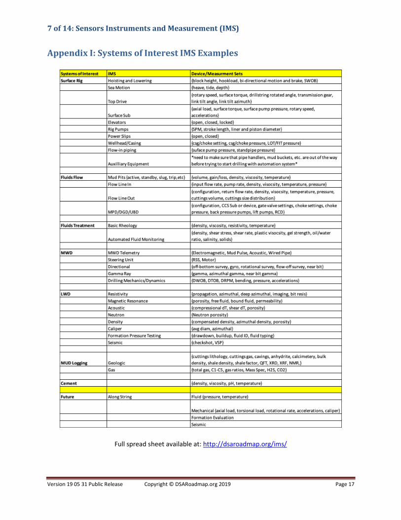
Appendix I: Systems of Interest IMS Examples
Full spread sheet available at: http://dsaroadmap.org/ims/