sensor display system - university of victoriaweb.uvic.ca/~salam/phd/courses/ceng355/report.pdf ·...
TRANSCRIPT

Sensor Display System
Lab Project Report
Submitted by
Student Name: Shahid Alam
Student ID: XXXXXXXXX
Course: CENG 355
December 04, 2008
1

I. Introduction
This report describes the details of the project completed as part of the lab for the course CENG
355 Microprocessor-Based Systems. This lab is based on the PowerPC family of microprocessors to
develop embedded systems for control and communication. In this lab we developed a sensor display
system which is responsible for reading, sensing and monitoring frequency, temperature and voltage. We
were provided with a microprocessor-based development board, MBX860, with software development
environment, SingleStep On Chip (PowerPC 8xx) Debugging System. We were also given a breadboard
with devices to develop our own circuit for the system. There was one bonus part in the project, which
was to generate a PWM signal using the input signal frequency from the function generator.
We have divided this report into the following six sections: Section I gives a brief introduction of
the report, Section II describes the problem, Section III describes the detailed design and implementation
including the bonus part of the project, Section IV lists the tests performed and the results obtained
during the project, Section V gives a discussion, which includes limitations, problems faced and errors
while completing the project, and finally Section VI concludes the report.
II. Problem Description
To develop a sensor display system which monitors frequency, temperature and voltage using a
MBX860 board and a serial analog to digital converter (ADC0838). The detail specifications of the project
are as follows:
Develop a system which senses and displays:
1. The frequency of a signal generated by a function generator.
2. The temperature coming from an LM35 temperature sensor.
3. The digital value of an analog voltage from the potentiometer.
The sensed values should be updated periodically to the terminal. The serial parallel interface
(SPI) should be used to connect the ADC to the MBX860 board. The temperature should be converted to
degrees Celsius.
Bonus: Output a Pulse Width Modulated (PWM) signal with a frequency equal to K x Input signal
frequency, where K is the value on the potentiometer scaled between 0 and 1, i.e; as the value of
(voltage from) the potentiometer decreases, the frequency of the PWM signal should also decrease and
2

vice versa.
III. Design and Implementation
Figure 1.1 gives an overview of the architecture of the sensor display system. As described in the
problem description we need to read three signals: one from the potentiometer, one from the temperature
sensor and the last one from the function generator.
A potentiometer is a three terminal resistor with a sliding contact that forms an adjustable voltage
divider. The divided analog output voltage from the potentiometer is converted to a digital signal using an
analog to digital converter and is fed to a microprocessor for monitoring. A temperature sensor is used to
sense the room temperature and output an analog signal which is converted to a digital signal using an
analog to digital converter and is fed to a microprocessor for monitoring. A function generator is used to
generate a frequency to be monitored by the microprocessor. These three signals are read and displayed
by the microprocessor for monitoring.
Figure 1.1. Overview of the architecture of the sensor display system
3

Following is a list of all the hardware used in the project:
1. MBX860 Embedded development board
2. IBM Compatible PC
3. ADC0838 National semiconductor serial 8-channel 8-bit ADC
4. LM35 Temperature Sensor
5. 10K Potentiometer
6. Breadboard
7. Ribbon cables
Following is a list of all the software used in the project:
1. SingleStep On Chip (PowerPC 8xx) Debugging System
2. Windows XP Operating System
3. Windows HyperTerminal
4. Windows TextPad 32-bit edition
Now we describe in detail the design and implementation of the sensor display system. As
described in the problem description, we used the MBX860 embedded development board in our design.
The MPC860 microprocessor on this board is a PowerPC architecture based controller. The CPU on the
MPC860 is a 32-bit microprocessor which implements the PowerPC architecture, incorporating memory
management units (MMUs), instruction and data caches. The Following is a list of features [1] that we
used in our design:
1. Embedded MPC860 Core
◦ Single-issue, 32-bit core (compatible with the PowerPC architecture definition) with 32-bit
general-purpose registers (GPRs)
2. Up to 32-bit data bus (dynamic bus sizing for 8, 16, and 32 bits)
3. 32 address lines.
4. Memory controller (eight banks)
5. General-purpose timers
◦ Four 16-bit timers or two 32-bit timers
6. Interrupts
7. Parallel I/O Ports
◦ Four general purpose I/O ports.
8. Communications processor module (CPM).
9. One SPI (serial peripheral interface)
◦ Supports master and slave modes
4

Figure 1.2 is the circuit diagram for the sensor display system. The following sections describe
how the three signals are read and displayed by the microprocessor for monitoring using the circuit in
Figure 1.2. We also describe how we generate the PWM signal. The parallel ports of the MBX860
embedded development board are connected to an expansion board for easy connections as shown in
Figure 1.2. Appendix 'A' gives a detailed listing of all the software as source code, implemented for the
project. There are four files: main.c, main.h, spi.c and spi.h.
Figure 1.2. Circuit diagram for the sensor display system
5

Measuring the frequency generated by a function generator
As shown in Figure 1.2 the signal from the frequency generator is connected to the expansion
board pin number 3, which is connected to port A pin number 7, PA7. To read the frequency coming from
the function generator we used one of the 16-bit timers, and installed a Timer Interrupt Service Routine
(ISR) to compute the period of the signal and configure PA7 to be TIN1, which is one of the inputs to
Timer 1 as shown in Figure 1.2. This period is used to calculate the frequency of this incoming signal.
The Timer ISR _TMRisr(), see Appendix 'A' for a complete code listing, computes the period and the
main task, Mtask(), see Appendix 'A' for a complete code listing, computes and prints the frequency to
the HyperTerminal as follows:
uint_16 freq;freq = 50000000 / period;printf ("%5i Hz", freq);
Communicating with ADC0838 using SPI
The serial peripheral interface (SPI) [1] allows the MPC860 to exchange data between other
devices. The SPI is a full-duplex, synchronous, character-oriented channel that supports a four-wire
interface (receive, transmit, clock and slave select). The SPI block consists of a transmitter and receiver,
an independent baud rate generator, and a control unit. The transmitter and receiver sections use the
same clock, which is derived from the SPI baud rate generator in master mode and generated externally
in slave mode. During an SPI transfer, data is sent and received simultaneously.
We used SPI to monitor the signals from the ADC as shown in Figure 1.2. We used SPI as the
master in our project. There are two pins, SPIMOSI (SPI master out slave in) and SPIMISO (SPI master
in slave out), of SPI that are used to transmit and receive signals respectively. Two other pins SPISEL
and SPICLK are used to select the ADC using the CS pin of ADC and provide the clock to the ADC
respectively. To bring the clock frequency down, the system clock (which is 50 MHz) is divided by 16 and
prescaled by 64. So SPICLK is approximately (50000000 / (16 x 64)) 50 Khz which is also connected to
the ADC clock, which is CLK in Figure 1.2. ADC0838 has 8 channels [2] for conversion. The pin DI is
used to select these channels and the pin DO for the output.
We first configured the SPI and selected port B to be the four pins, (SPIMISO, SPIMOSI, SPICLK
and SPISEL) of SPI as described above. Then we enabled all the interrupts and selected the appropriate
6

mode of SPI, see Appendix 'A' for source code details. We first selected the channel by sending serial
bits (0x30 for channel 0 and 0x38 for channel 1) [2] to DI pin of ADC0838, and enabled the SPI transfer
and made the CS pin of ADC0838 low, to start conversion. Then we made the processor wait for the
interrupt and made the CS high after receiving the interrupt. The value was read from the DO pin into the
local buffer and output to the HyperTerminal. The function SPI_tx_rx(), Appendix 'A', is used to
transmit and receive as described above.
The temperature coming from an LM35 temperature sensor
We used channel 0 of the ADC0838 chip to measure the temperature from the LM35 temperature
sensor [3] as shown in Figure 1.2. The output voltage of the LM35 is directly calibrated in Degree Celsius
(Centigrade) using a linear scale factor of + 10.0 mV per Degree Celsius. In our project when we read the
voltage at the LM35 output pin it was around 250 mV, after the conversion through ADC the SPI was
reading it to be around 12 - 13. So to convert that to 250 mV we multiplied this number by (2 x 10).
Dividing this value by 10 we converted this voltage into Degree Celsius (Centigrade) as follows and
displayed it on the HyperTerminal:
/* To store temperature */char temperature[4];/* To select channel 0 */char channel_0[4]= { 0x00, 0x30, 0x00, 0x00 };uint_16 temp; SPI_tx_rx(temperature, channel_0); temp = (int)temperature[0]; temp = (temp * 2 * 10) / 10; printf (" %5i C", temp);
The digital value of an analog voltage from the potentiometer
We used channel 1 of the ADC0838 chip to measure the analog voltage from the potentiometer
[3] as shown in Figure 1.2. The input voltage is 5 V, the output voltage after the conversion through the
ADC ranged from 0 – 255. One volt is represented by 51 (255 / 5) steps. So we multiplied the voltage
read by 1000 and divided by 51 to convert it into millivolts and displayed it on the HyperTerminal as
follows:
7

/* To store volatage */char voltage[4];/* To select channel 1 */char channel_1[4]= { 0x00, 0x38, 0x00, 0x00 };uint_16 volt;SPI_tx_rx(voltage, channel_1);volt = (int)voltage[0];volt = (volt * 1000) / 51;printf (" %5i mV\n\n", volt);
Bonus: Output a PWM signal with frequency equal to K x Input Signal Frequency, where K is the value on the potentiometer scaled between 0 and 1
In the above Section we normalized / converted the potentiometer voltage range:0 V - 5 VTo0 mV - 5000 mV
We multiplied the input signal frequency, which is the frequency generated by the function
generator as shown in Figure 1.2 by this voltage range, and then divided the result by 5000 to
normalize / scale the value of the multiplier K between 0 and 1, and displayed the value on the
HyperTerminal as follows:
uint_16 PWM;PWM = (freq * volt) / 5000;printf ("\nPWM Signal (Frequency) -> %5i Hz", PWM);
where volt and freq are read and computed in above sections.
As an example if we generate a frequency of 1000 Hz and the potentiometer setting is at
maximum i.e; the voltage reading is 5000 mV then the PWM will be 1000 Hz. As we move the setting of
potentiometer towards minimum, the PWM value will start decreasing and will be 0 at the minimum
potentiometer setting, at this time the voltage reading will be 0 mV. See Appendix 'B' for a graph with
these results.
8

Figure 1.3. Frequency Read by the 16-bit Timer of the MPC860
9

IV. Testing and Results
We perform tests for reading the frequency from the function generator. Figure 1.3 shows the
graph for the tests performed to measure the frequency from the function generator.
We took 42000 readings for frequencies from 762 Hz to 2500 Hz. Figure B.1 in Appendix 'B' is
the graph for these readings of the frequencies set on the function generator. Figure 1.3 is the graph for
these readings of the frequencies read by the MPC860 16-bit Timer.
The first few readings in Figure 1.3 are the readings for the frequency 762 Hz. The lowest
frequency that can be read by the MPC860 16-bit Timer is 763 Hz, as will be explained in more detail in
the next Section. Therefore the MPC860 was not able to read the frequency 762 Hz accurately and as a
result we got these first few readings for 762 Hz as random numbers from 600 – 2031.
The temperature reading inside the lab varied between 20 – 26 Degrees Celsius at different times
of the day. The input voltage to the potentiometer was 5 V. After normalizing we were able to change the
output voltage of the potentiometer from 0 mV – 5000 mV as shown in Figure 1.4.
As described in the problem specifications for the generation of the PWM frequency, we
multiplied the Input Signal Frequency (Frequency from the function generator) with a normalized voltage
ranging from 0 mV - 5000 mV from the potentiometer which was then scaled between 0 and 1. We took
readings for 12 frequencies: 800 Hz, 900 Hz, 1000 Hz, 2000 Hz, 3000 Hz, 4000 Hz, 5000 Hz, 6000 Hz,
7000 Hz, 8000 Hz, 9000 Hz and 10000 Hz. Figure 1.4 displays the results as a graph for the 10000 Hz
frequency. The voltage from the potentiometer and the PWM signal frequency are displayed on the X and
Y axises respectively. The results for other frequencies as graphs are displayed in Appendix 'B'. As we
changed the resistance of the potentiometer the output voltage increased from 0 mV – 5000 mV and so
did the PWM frequency from 0 – 10000 Hz as shown in Figure 1.4.
V. Discussion
During the testing we found one of the limitations of the frequency measurement. The minimum
frequency that this system can read is 763 Hz as shown in Figure 1.3. The reason for this is the size of
the MPC860 Timer used, which is 16-bit. So the maximum time period read using this Timer is 216, which
is equal to 65536 and:
10

Figure 1.4. Testing Results for Generation of Pulse Width Modulated Frequency
Frequency = 1 / Time period= (1 / 65536) x 50000000 = 762.95
Sometimes while performing tests the frequency generated by the function generator and the
frequency read by the MPC860 Timer were not the same as shown by the graphic curves in Figures 1.3
and B.1. For example, by examining these two graphs carefully we can see that there are some minor
differences between these two curves around the 30000 readings. The average percent error for these
readings is 0.003/100. We generated the test data, which consisted of changing the frequency on the
function generator and the resistance on the potentiometer manually. As a result the test data generated
11

may not be very accurate, but we decreased the chances of this error by taking more readings as shown
in Figure 1.3 and the graphs in Appendix 'B'.
One of the problems that we faced while writing the software was how to interface the software
with the hardware. All the configurations that were done for the SPI and the Timer, and the process of
transmitting and receiving signals to and from the ADC, involved interfacing the hardware with the
software. This gave us real life experience working directly with the software and hardware.
VI. Conclusion
The purpose of this project was to develop a sensor display system which monitors frequency,
temperature and voltage, using the MBX860 board and a serial analog to digital converter (ADC0838). In
this project report we have presented a design of this system and described how the design has been
implemented using the software and hardware. We have also shown the tests performed and the results
obtained. We end the report with a discussion of some of the limitations, errors and problems faced. The
author has learned a lot during this project while reading manuals on PowerPC, ADC0838 and LM35, and
gained experience of working directly with software and hardware and how they interface with each other.
12

References
[1] MPC860 PowerQUICC Family User's Manual Manual, MPC860UM 3/2003 REV 2 © Motorola, Inc.
[2] ADC0831/ADC0832/ADC0834/ADC0838, 8-Bit Serial I/O A/D Converters with Multiplexer Options
Manual July 2002, © National Semiconductor, Inc.
[3] LM35 Precision Centigrade Temperature Sensors Manual November 2000, © National
Semiconductor, Inc.
13

Appendix 'A'
Source Code Listing
/*****************************************************************************\* filename: main.h ** ** submitted by: Shahid Alam as part of the course Project report ** ** course: CENG 355 ** ** dated: November 21, 2008 ** ** Description: This is the main header file for the main program. ** *\*****************************************************************************/
#ifndef __main_h__#define __main_h__
/* * ============================================================================= * Defines * ============================================================================= */#define MAIN_TASK 6
/* * ============================================================================= * Prototype definitions for task functions * ============================================================================= */void MTask(uint_32 tmp);
#endif /* __main_h__ */
14

/*****************************************************************************\* filename: main.c ** ** submitted by: Shahid Alam as part of the course Project report ** ** course: CENG 355 ** ** dated: November 21, 2008 ** ** Description: This is the main file that creates the main task. The main ** task is responsible for creating a timer ISR to compute the ** frequency of an external signal. It also calls the SPI_tx_rx ** method to read the temperature and voltage from the ADC. ** *\*****************************************************************************/
#include <mqx.h>#include <target.h>#include <bsp.h>#include <mpc860.h>#include "main.h"#include "spi.h"
/* * ========================================================================== * List for creating tasks * ========================================================================== */TASK_TEMPLATE_STRUCT MQX_template_list[] ={
{ MAIN_TASK, MTask, 2000L, 9L, "MTask", MQX_AUTO_START_TASK, 0L, 0L},{ 0L, 0L, 0L, 0L, 0L, 0L, 0L, 0L}
};
/* * ============================================================================= * Global variables * ============================================================================= */void _TMRisr(pointer ad);volatile uint_16 last_timer;
15

volatile uint_16 period;/* * ============================================================================= * MTask * ============================================================================= */void MTask(uint_32 tmp){
/* Local variables */volatile MPC860_STRUCT _PTR_ mpc860_ptr;volatile MPC860_REGISTERS_STRUCT _PTR_ reg_ptr;volatile MPC860_SPI_PRAMAMETER_STRUCT _PTR_ spi_ptr;
char voltage[AD_SIZE]; /* To store volatage */char temperature[AD_SIZE]; /* To store temperature */char channel_0[AD_SIZE]= { 0x00, 0x30, 0x00, 0x00 }; /* To select channel 0 */char channel_1[AD_SIZE]= { 0x00, 0x38, 0x00, 0x00 }; /* To select channel 1 */
/* Other local temporary variables */uint_16 volt, temp, freq, PWM;int i;
/* * -------------------------------------------------------------------------- * Initialize the h/w data structure pointers. * -------------------------------------------------------------------------- */mpc860_ptr = _mpc860_get_immr();reg_ptr = &mpc860_ptr->REGISTERS;spi_ptr = (MPC860_SPI_PRAMAMETER_STRUCT_PTR)&(mpc860_ptr->PARAMETERS.SPI);
/* * -------------------------------------------------------------------------- * Install the Timer interrupt service routine. * -------------------------------------------------------------------------- */if (_int_install_isr(MPC860_TIMER1_VECTOR, _TMRisr, NULL) == NULL)
printf("Cannot install notifier!!!\n");
/* 0. Config PA7 to be TIN1 */reg_ptr->PAPAR |= MPC860_PIO_A_CLK1;
16

reg_ptr->PADIR = 0x0000;
/* 1. Reset timer 1 */reg_ptr->TGCR = 0x0000; /* Binary 0000 0000 0000 0000 */
/* * 2. Setup timer 1 * - prescaler divide by 1 * - capture on rising TIN1 edge and enable interrupt on capture event * - free running * - internal general system clock */reg_ptr->TMR1 = 0x0042; /* Binary 0000 0000 0100 0010 */
/* 3. Clear the timer 1 counter */reg_ptr->TCN1 = 0x0000; /* Binary 0000 0000 0000 0000 */
/* 4. Clear any previous timer 1 events. */reg_ptr->TER1 = 0xFFFF; /* Binary 1111 1111 1111 1111 */
/* 5. Enable timer 1 interrupts in the CPIC */reg_ptr->CISR |= MPC860_INT_TIMER1;
/* 6. Enable timer 1 to begin counting. */reg_ptr->TGCR = 0x0001; /* Binary 0000 0000 0000 0001 */
_SPIinit();
/* * ---------------------------------------------------------------------------- * Infinite loop that gets and computes the frequency, temperature and voltage * ---------------------------------------------------------------------------- */while (1) {
printf (" Weather Station\n\n");printf ("Frequency Temperature Voltage\n\n");
freq = 50000000 / period;printf ("%5i Hz", freq);
/*
17

* LM35 scale: * + 10.0 mV / degree Celsius (Centigrade) * When we read the voltage at the LM35 * output pin it is around 250 mV, but the * SPI is reading it as around 12 / 13. * So to convert that to 250 mV we multiply * this number by by (2 x 10). By dividing * ths value by 10 we convert this voltage * into centigrade. */SPI_tx_rx(temperature, channel_0);temp = (int)temperature[0];temp = (temp * 2 * 10) / 10;printf (" %5i C", temp);
/* * The input voltage range is: * (0 V = 0) - (5 V = 255) * One volt can be represented by 51 (255/5) steps * So we multiply the voltage read by 1000 and * divide by 51 to convert it into milli volts. */SPI_tx_rx(voltage, channel_1);volt = (int)voltage[0];volt = (volt * 1000) / 51;printf (" %5i mV\n\n", volt);
/* * In the above we normalized the voltage range: * * 0 V - 5 V * * To * * 0 mV - 5000 mV * * We multiply the frequency by this voltage * range and then divide the result by 5000 * to normalize / scale the value of the * multiplier K between 0 and 1. *
18

* To test this read a frequency of 1000 Hz * If your potentiometer setting is at maximum * i.e; your voltage reading is 5000 mV * then your PWM will be 1000 Hz. As you move * the setting of potentiometer towards minimum, * the PWM value will start decreasing and will be * 0 at the minimum potentiometer setting, when the * voltage reading will be 0 mV. */PWM = (freq * volt) / 5000;printf ("\nPWM Signal (Frequency) -> %5i Hz", PWM);
/* Delay using a loop */for (i = 0; i < 10000000; i++) ;/* Clear screen */printf("\033[2J");
}
_mqx_exit(0);} /* MTask */
/* * ============================================================================= * Timer ISR * ============================================================================= */void _TMRisr(pointer ad){
/* Local variables */volatile MPC860_STRUCT _PTR_ mpc860_ptr;volatile MPC860_REGISTERS_STRUCT _PTR_ reg_ptr;
/* * -------------------------------------------------------------------------- * Initialize the h/w data structure pointers * -------------------------------------------------------------------------- */mpc860_ptr = _mpc860_get_immr();reg_ptr = &mpc860_ptr->REGISTERS;
/*
19

* 1. Compute the period as the difference between the timer * capture register 1 and the last timer value. */period = reg_ptr->TCN1 - last_timer;
/* 2. Save the timer capture register 1 value for next time. */last_timer = reg_ptr->TCN1;
/* 3. Clear the timer 1 capture event. */reg_ptr->TER1 = 0xFFFF; /* Binary FFFF FFFF FFFF FFFF */
/* 4. Re-enable the timer 1 interrupt.*/reg_ptr->CISR |= MPC860_INT_TIMER1;
} /* _TMRisr */
/*****************************************************************************\* filename: spi.h ** ** submitted by: Shahid Alam as part of the course Project report ** ** course: CENG 355 ** ** dated: November 21, 2008 ** ** Description: This is the spi header file for the SPI program. ** ** The functions defined are: ** ** _SPIinit -- the SPI initialization function ** SPI_tx_rx -- a function which performs the actual SPI ** communication ** _SPIisr -- the SPI interrupt service routine ** *\*****************************************************************************/
#ifndef __spi_h__#define __spi_h__
20

/* * ============================================================================= * Defines * ============================================================================= */#define AD_SIZE 16#define DA_SIZE 16#define RX_SIZE 8#define TX_SIZE 8#define SPI_RX_BUFFER_SIZE AD_SIZE + RX_SIZE /* RX buffer size */#define SPI_TX_BUFFER_SIZE DA_SIZE + TX_SIZE /* TX buffer size */
/* * ============================================================================= * Prototype definitions for task functions * ============================================================================= */uint_32 SPI_tx_rx(volatile unsigned char *ad_in, volatile unsigned char *da_out);void _SPIinit(void);char SPIstatus(void);
#endif /* __spi_h__ */
/*****************************************************************************\* filename: spi.c ** ** submitted by: Shahid Alam as part of the course Project report ** ** course: CENG 355 ** ** dated: November 21, 2008 ** ** Description: This is code for the programming of the MBX860 Serial ** Periferal Interface. ** ** The functions implemented are: ** ** _SPIinit -- the SPI initialization function ** SPI_tx_rx -- a function which performs the actual SPI ** communication ** _SPIisr -- the SPI interrupt service routine *
21

* ** NOTE: Portions of the code were obtained from init_bsp.c and ** Mpc860.h. ** *\*****************************************************************************/
/*****************************************************************************\* Local Includes *\*****************************************************************************/#include <mqx.h>#include <bsp.h>#include <mpc860.h>#include "spi.h"
/*****************************************************************************\* Local Prototypes *\*****************************************************************************/void _SPIisr(pointer ad); /* SPI ISR prototype */
/*****************************************************************************\* Local Defines *\*****************************************************************************//* SPI defines. See SPMODE register definitions page 31-7 MPC860 manual. */#define SPI_CHAR_LENGTH_8 0x0070 /* 8 Bit character length */#define SPI_CHAR_LENGTH_14 0x00D0 /* 14 Bit character length */#define SPI_CHAR_LENGTH_16 0x00F0 /* 16 Bit character length */#define SPI_PM_VALUE_SLOW 0x000F
/* Port C General purpose I/O lines that generate interrupts defines. */#define PC6_MASK 0x00000040#define PC7_MASK 0x00000200#define PC6_PIN 0x0200#define PC7_PIN 0x0100
/*****************************************************************************\* Global (within file) Variables *\*****************************************************************************/volatile char spi_status;volatile pointer td_ptr;
22

/*****************************************************************************\* Function Declarations *\*****************************************************************************/
/* * ============================================================================ * SPI_tx_rx * * SPI_tx_rx is called when you have data to transmit and receive. * ============================================================================ */uint_32 SPI_tx_rx(volatile unsigned char *ad_in, volatile unsigned char *da_out){ int i;
volatile MPC860_STRUCT _PTR_ mpc860_ptr; volatile MPC860_REGISTERS_STRUCT _PTR_ reg_ptr; volatile MPC860_SPI_PRAMAMETER_STRUCT _PTR_ spi_ptr;
volatile MPC860_SPI_BD_STRUCT_PTR rx_bd_ptr; volatile MPC860_SPI_BD_STRUCT_PTR tx_bd_ptr;
/* * -------------------------------------------------------------------------- * Get the task descriptor so that we know which task to ready. * -------------------------------------------------------------------------- */ if ((td_ptr = _task_get_td(_task_get_id())) == NULL) printf ("Cannot get task descriptor!");
/* * -------------------------------------------------------------------------- * Initialize the h/w data structure pointers. * -------------------------------------------------------------------------- */ mpc860_ptr = _mpc860_get_immr(); reg_ptr = &mpc860_ptr->REGISTERS; spi_ptr = (MPC860_SPI_PRAMAMETER_STRUCT_PTR)&(mpc860_ptr->PARAMETERS.SPI);
23

/* * -------------------------------------------------------------------------- * Determine where to copy the data to for tx and from for rx. * -------------------------------------------------------------------------- */ rx_bd_ptr = (MPC860_SPI_BD_STRUCT_PTR) ((uint_32)(spi_ptr->RBASE) + (uint_32)(mpc860_ptr)); tx_bd_ptr = (MPC860_SPI_BD_STRUCT_PTR) ((uint_32)(spi_ptr->TBASE) + (uint_32)(mpc860_ptr));
/* * -------------------------------------------------------------------------- * Re-initiallize the RxBD information. * -------------------------------------------------------------------------- */ rx_bd_ptr->LENGTH = 0x0000; rx_bd_ptr->CONTROL = MPC860_BD_WRAP | MPC860_BD_INTERRUPT | MPC860_BD_RX_EMPTY;
/* * -------------------------------------------------------------------------- * Re-initiallize the TxBD information and copy the data that is to be * transmitted into the buffer. * -------------------------------------------------------------------------- */ _mem_copy(da_out, tx_bd_ptr->BUFFER, DA_SIZE); _dcache_flush_mlines(tx_bd_ptr->BUFFER, SPI_TX_BUFFER_SIZE); tx_bd_ptr->LENGTH = SPI_TX_BUFFER_SIZE; tx_bd_ptr->CONTROL = MPC860_BD_WRAP | MPC860_BD_INTERRUPT | MPC860_BD_TX_FULL | MPC860_BD_TX_LAST_IN_FRAME;
/* * -------------------------------------------------------------------------- * Enable the SPI transfer and clear any previous events that might exist. * -------------------------------------------------------------------------- */ reg_ptr->SPCOM |= MPC860_SPCOM_STR;
24

reg_ptr->SPIE = 0xFF; reg_ptr->CISR |= MPC860_INT_SPI;
/* * -------------------------------------------------------------------------- * Wait until the SPI has finished the data transfer, and reset the * spi_status to indicate the transfer is complete. _task_block waits until * the spi interrupt occurs, and then we need to ensure that the transfer is * complete by waiting until the SPI Select line is de-asserted. * -------------------------------------------------------------------------- */
reg_ptr->PBDAT &= ~MPC860_PIO_B_SPISEL; /* Output Low to make CS low and */ /* start conversion */ _task_block(); reg_ptr->PBDAT |= MPC860_PIO_B_SPISEL; /* Output High to make CS high */ /* and end conversion */ spi_status = 0x00;
/* * -------------------------------------------------------------------------- * Copy the received data into the proper memory locations. * -------------------------------------------------------------------------- */ _dcache_invalidate_mlines(rx_bd_ptr->BUFFER, SPI_RX_BUFFER_SIZE); _mem_copy(rx_bd_ptr->BUFFER, ad_in, AD_SIZE);
/* * -------------------------------------------------------------------------- * Reset the task descriptor, so that the SPI interrupt won't _task_ready a * possibly ready task. * -------------------------------------------------------------------------- */ td_ptr = NULL;
return ( 0 );} /* SPI_tx_rx */
25

/* * ============================================================================ * _SPIinit * * Initialize the SPI and create the appropriate buffers on the MBX860 EVB to * facilitate communications. * ============================================================================ */void _SPIinit(void){ volatile MPC860_STRUCT _PTR_ mpc860_ptr; volatile MPC860_REGISTERS_STRUCT _PTR_ reg_ptr; volatile MPC860_SPI_PRAMAMETER_STRUCT _PTR_ spi_ptr;
volatile MPC860_SPI_BD_STRUCT_PTR rx_bd_ptr; volatile MPC860_SPI_BD_STRUCT_PTR tx_bd_ptr;
/* * -------------------------------------------------------------------------- * Initialize the h/w data structure pointers. * -------------------------------------------------------------------------- */ mpc860_ptr = _mpc860_get_immr(); reg_ptr = &mpc860_ptr->REGISTERS; spi_ptr = (MPC860_SPI_PRAMAMETER_STRUCT_PTR)&mpc860_ptr->PARAMETERS.SPI;
/* * -------------------------------------------------------------------------- * Install the SPI interrupt service routine. * -------------------------------------------------------------------------- */ if (_int_install_isr(MPC860_SPI_VECTOR, _SPIisr, NULL) == NULL) printf("Cannot install notifier!!!\n");
/* * -------------------------------------------------------------------------- * Configure port B to enable SPIMISO, SPIMOSI, and SPICLK by setting the * appropriate bits in PBPAR (Port B Pin Assignment Register) and PBDIR (Port * B Data Direction Register) and clearing the appropriate bits in PBODR * (Port B Open-Drain Register). * --------------------------------------------------------------------------
26

*/ reg_ptr->PBPAR |= MPC860_PIO_B_SPIMOSI | MPC860_PIO_B_SPIMISO | MPC860_PIO_B_SPICLK; reg_ptr->PBDIR |= MPC860_PIO_B_SPIMOSI | MPC860_PIO_B_SPIMISO | MPC860_PIO_B_SPICLK; reg_ptr->PBODR &= ~(MPC860_PIO_B_SPIMOSI | MPC860_PIO_B_SPIMISO | MPC860_PIO_B_SPICLK);
reg_ptr->PBODR &= ~MPC860_PIO_B_SPISEL; /* drive port B to produce output */ reg_ptr->PBPAR &= ~MPC860_PIO_B_SPISEL; /* General purpose I/O */ reg_ptr->PBDIR |= MPC860_PIO_B_SPISEL; /* For general purpose output */
/* * -------------------------------------------------------------------------- * Write RBASE and TBASE in the SPI parameter RAM to point to the RxBD and * TxBD entries that we allocater here in the dual-port RAM. * -------------------------------------------------------------------------- */
/* TX BD setup here */ _mpc860_bd_alloc(1, &tx_bd_ptr); /* Convert to 16 bit value */ if ( (uint_32)tx_bd_ptr == (uint_32)-1 ) printf("Out of BD's!"); spi_ptr->TBASE = (uint_16)((uchar_ptr)tx_bd_ptr - (uchar_ptr)mpc860_ptr);
/* RX BD setup here */ _mpc860_bd_alloc(1, &rx_bd_ptr); /* Convert to 16 bit value */ if ( (uint_32)rx_bd_ptr == (uint_32)-1 ) printf("Out of BD's!"); spi_ptr->RBASE = (uint_16)((uchar_ptr)rx_bd_ptr - (uchar_ptr)mpc860_ptr);
/* * -------------------------------------------------------------------------- * Execute the INIT RX AND TX PARAMETERS command by writing 0x0051 to CPCR. * -------------------------------------------------------------------------- */
27
while (reg_ptr->COMMAND & 0x0001) ; /* wait until ready */ reg_ptr->COMMAND = 0x0051; /* send the command */ while (reg_ptr->COMMAND & 0x0001) ; /* wait until processed */
/* * -------------------------------------------------------------------------- * Write 0x0001 to the SDCR to initialize the SDMA configuration register * (SDCR). * -------------------------------------------------------------------------- */ reg_ptr->SDCR = 0x0001;
/* * -------------------------------------------------------------------------- * Write RFCR and TFCR with 0x10 for normal operation. * -------------------------------------------------------------------------- */ spi_ptr->RFCR = 0x10; spi_ptr->TFCR = 0x10;
/* * -------------------------------------------------------------------------- * Write MRBLR with the maximum number of bytes per Rx buffer. * -------------------------------------------------------------------------- */ spi_ptr->MRBLR = SPI_RX_BUFFER_SIZE;
/* * -------------------------------------------------------------------------- * Initialize the RxBD. * -------------------------------------------------------------------------- */ rx_bd_ptr->CONTROL = MPC860_BD_WRAP | MPC860_BD_INTERRUPT | MPC860_BD_RX_EMPTY; rx_bd_ptr->LENGTH = 0x0000; rx_bd_ptr->BUFFER = (uchar_ptr)_mem_alloc_system_zero(SPI_RX_BUFFER_SIZE); if (rx_bd_ptr->BUFFER == NULL) printf("Could not allocate buffer memory!");
28

/* * -------------------------------------------------------------------------- * Initialize the TxBD. * -------------------------------------------------------------------------- */ tx_bd_ptr->CONTROL = MPC860_BD_WRAP | MPC860_BD_INTERRUPT | MPC860_BD_TX_FULL | MPC860_BD_TX_LAST_IN_FRAME; tx_bd_ptr->LENGTH = SPI_TX_BUFFER_SIZE; tx_bd_ptr->BUFFER = (uchar_ptr)_mem_alloc_system_zero(SPI_TX_BUFFER_SIZE); if (tx_bd_ptr->BUFFER == NULL) printf("Could not allocate buffer memory!");
/* * -------------------------------------------------------------------------- * Write 0xFF to SPIE to clear any previous events. * -------------------------------------------------------------------------- */ reg_ptr->SPIE = 0xFF;
/* * -------------------------------------------------------------------------- * Write 0x37 to SPIM to enable all possible SPI interrupts. * -------------------------------------------------------------------------- */ reg_ptr->SPIM = MPC860_SPIE_MME | MPC860_SPIE_TXE | MPC860_SPIE_BSY | MPC860_SPIE_TXB | MPC860_SPIE_RXB;
/* * -------------------------------------------------------------------------- * Write 0x0000020 to the CPM interrupt mask register (CIMR). This sets * CIMR[SPI] to enable SPI-generated system interrupts. * -------------------------------------------------------------------------- */ reg_ptr->CIMR |= MPC860_INT_SPI;
29

/* * -------------------------------------------------------------------------- * Write 0x3FDF to SPMODE to enable normal operation, master mode, enable the * SPI 8-bit characters, clk polarity low, and clk phase as low. * * 0x3FFF = 0011 1111 1111 1111 B * * -------------------------------------------------------------------------- */ reg_ptr->SPMODE = MPC860_SPMODE_REV /* Normal operation */
| SPI_CHAR_LENGTH_16 /* 8 for channel + 8 for data TX */| MPC860_SPMODE_EN /* Enable SPI */| MPC860_SPMODE_CP /* Start toggling at the start of data TX */| MPC860_SPMODE_CI /* Inactivate state of SPICLK is high */| MPC860_SPMODE_DIV16 /* BRGCLK / 16 is the input to the SPI BRG*/| MPC860_SPMODE_MASTER/* Master mode */| SPI_PM_VALUE_SLOW; /* Prescale divider by 4x6=64,(16*64=1024)*/
} /* _SPIinit */
/* * ============================================================================ * _SPIisr * * This is the SPI interrupt service routine. It handles the completion of * the SPI transmission. * ============================================================================ */void _SPIisr(pointer ad){ volatile MPC860_STRUCT _PTR_ mpc860_ptr; volatile MPC860_REGISTERS_STRUCT _PTR_ reg_ptr; volatile MPC860_SPI_PRAMAMETER_STRUCT _PTR_ spi_ptr;
/* * -------------------------------------------------------------------------- * Initialize the h/w data structure pointers * -------------------------------------------------------------------------- */
30
mpc860_ptr = _mpc860_get_immr(); reg_ptr = &mpc860_ptr->REGISTERS;
/* * -------------------------------------------------------------------------- * Reset the interrupt and clear the SPI events. * -------------------------------------------------------------------------- */ reg_ptr->SPIE = 0xFF; reg_ptr->CISR |= MPC860_INT_SPI; spi_status = 0x55;
/* * -------------------------------------------------------------------------- * Ready the task, if appropriate. * -------------------------------------------------------------------------- */ if (td_ptr != NULL) _task_ready(td_ptr);} /* _SPIisr */
/* * ============================================================================ * SPIstatus * * Returns the value of the spi_status variable. * ============================================================================ */char SPIstatus(void){ return spi_status;} /* SPIstatus */
31

Build file provided with the SingleStep On Chip (PowerPC 8xx)Debugging System (SDS)
@echo offREMREM ============================================================================REM build.batREMREM This file compiles the project so that it can be downloaded by the SDSREM Debugger.REMREM set mqx_proj = project, Shown in bold below:REM This is where you can change the name of theREM directory where you want your output filesREM (with .elf extension etc) stored.REMREM set mqx_file = spi main, Shown in bold below:REM This is where you list all your C filesREMREM ============================================================================REM
REM Set the project nameset mqx_proj = project
REM mqx_file contains a list of the projects .c files without the .c extension.REM The list is space delimited.set mqx_file = spi mainREM ============================================================================REM YOU SHOULD NOT NEED TO WORRY ABOUT ANYTHING BELOW THIS POINT!REM ============================================================================
set mqx_bsp=mcmbx860set mqx_comp=dd
if exist %mqx_root% goto noinitif exist C:\PRECISE\MQX2.40\tools.bat call C:\PRECISE\MQX2.40\toolsif exist %mqx_root% goto noinitif exist D:\PRECISE\MQX2.40\tools.bat call D:\PRECISE\MQX2.40\toolsif not exist %mqx_root% goto notsup
32
:noinit
set mqx_old_path=%path%
set mqx=%mqx_root%\lib\%mqx_bsp%.%mqx_comp%if not exist %mqx%\nul goto syntaxif not exist %mqx%\bspsetup.bat goto syntaxif not exist %mqx_root%\build\%mqx_comp%.bat goto notsupgoto compile
:syntaxecho Syntax:echo.echo GO [OPT]echo.goto clean
:notsupecho BSP %mqx_bsp% is not supported with compiler %mqx_comp%.echo.goto clean
REMREM Start mqx_compilingREM:compile
echo ----------------------- Setting up Compiler Environment ------------------------
REM this sets up mqx_proc and bsp_entrycall %mqx%\bspsetupif .%mqx_proc% == . goto syntax
call %mqx_root%\build\%mqx_comp% %mqx_proc% %1 %2 %3 %4if .%mqx_psp% == . goto notsup
if not exist %mqx_proj%\nul mkdir %mqx_proj%cd %mqx_proj%
if exist errors del errors
33

call %mqx_root%\build\%mqx_comp% start
for %%x in (%mqx_file%) do call %mqx_root%\build\%mqx_comp% comp .. %%x
call %mqx_root%\build\%mqx_comp% linkcall %mqx_root%\build\%mqx_comp% clean
echo.echo ---------------------------- Displaying errors file ----------------------------type errors
cd ..REMREM Clean up environmentREM:clean
set mqx=set mqx_proj=set mqx_file=set mqx_comp=set mqx_bsp=set mqx_proc=set bsp_entry=set path=%mqx_old_path%set mqx_old_path=
:endREM EOF
34
Appendix 'B'
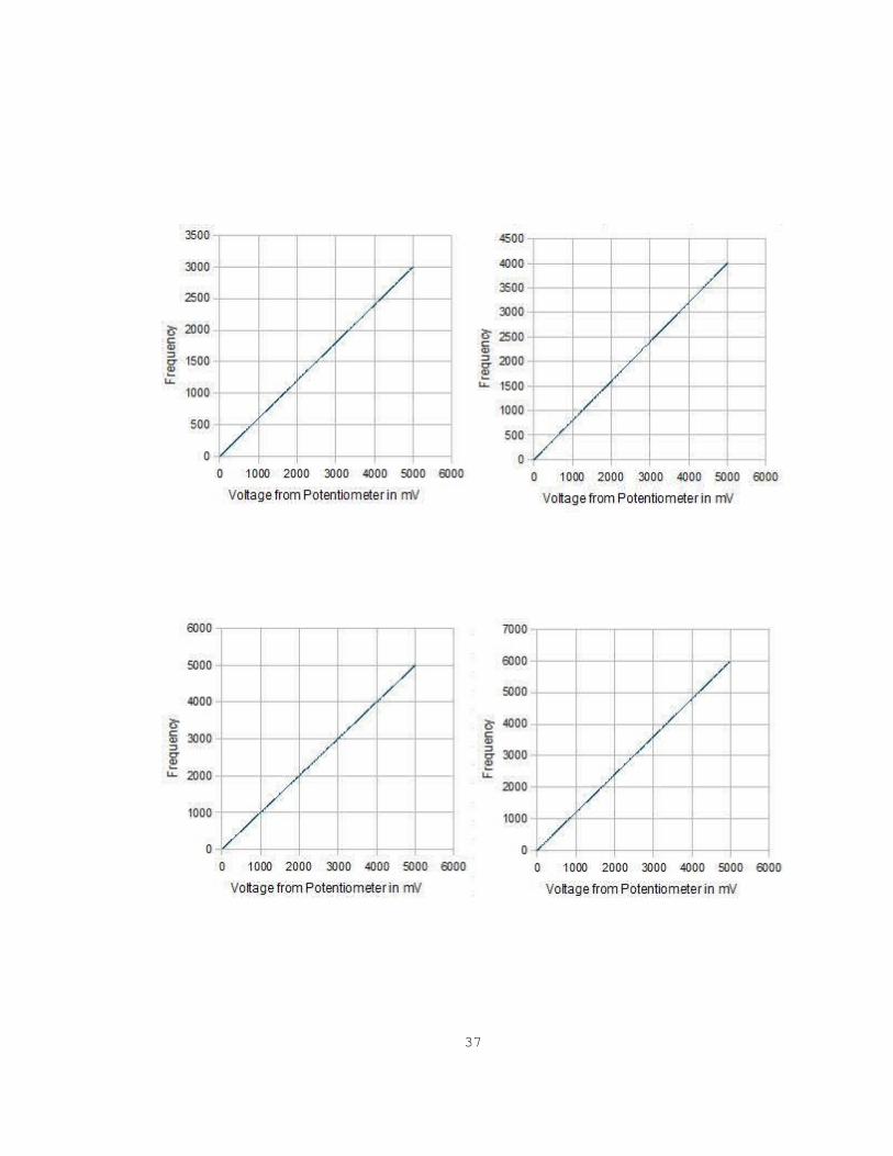
Testing Results for Generation of Pulse Width Modulated Frequencies
This project had a bonus problem which is as follows:
Output a Pulse Width Modulated (PWM) signal with frequency equal to K x Input signal
frequency, where K is the value on the potentiometer scaled between 0 and 1, i.e; as the value of
(voltage from) the potentiometer decreases, the frequency of the PWM signal should also decrease and
vice versa.
Following is the computation used to generate the PWM signal:
PWM = (Input signal frequency * Voltage from potentiometer) / 5000;
The input signal frequency is the frequency from the function generator. This Appendix shows the
testing results for the generation of the PWM signals (Frequencies). We took readings for 12 frequencies:
800 Hz, 900 Hz, 1000 Hz, 2000 Hz, 3000 Hz, 4000 Hz, 5000 Hz, 6000 Hz, 7000 Hz, 8000 Hz, 9000 Hz
and 10000 Hz. The following 12 Figures display the results as graph for these frequencies. The voltage
from the potentiometer and the PWM signal frequency are displayed on the X and Y axises respectively.
As we change the resistance of the potentiometer the output voltage increases from 0 mV – 5000 mV
and so does the PWM frequency from 0 – F Hz, where F ranges from 800 Hz – 10000 Hz as mentioned
in the above list of frequencies.
35

36
37

38

Figure B.1. Input Signal Frequency from the Function Generator
39