senior thesis final report
TRANSCRIPT
Senior Thesis Final Report
Alyssa Stangl | Structural Option | Advisor: Dr. Linda Hanagan
La Jolla Commons Phase II Office Tower San Diego, California
April 9, 2014
Steel Redesign, Vibration
Resistance, and Lateral
System Redesign

Thesis Abstract

3 | P a g e
Alyssa Stangl [Structural]
Acknowledgements and Thanks
I would first like to thank my loving boyfriend, Jeff Martin, and my Mom, Dad, and sisters who have
been so supportive through my college career and senior thesis. Without their love and support, I
would not be the person I am today. Thank you all for believing in me!
I would also like to thank the members of my AE family – Macenzie Ceglar, Sikandar Porter-Gill, Angela
Mincemoyer, Natasha Beck, and Kristin Sliwinski – for their support and for helping to keep me sane
during this whole process. Thank you for making me laugh and for helping me to enjoy this experience.
I would also like to extend a special thanks to Dr. Andres Lepage. Without the information I learned
from him at Penn State, I would not be the engineer I am today.
Finally, I would like to say thank you to some specific individuals that through their knowledge, advice,
and overwhelming support have made the completion of my senior thesis a reality!
Penn State Architectural Engineering Faculty:
o Dr. Linda Hanagan - Thank you for your support through all the ups and downs over the past few
years. Your help and encouragement has been invaluable. I am truly blessed to have worked
with you!
o Professor Heather Sustersic
o Professor Parfitt
Penn State Architectural Engineering Graduate Students:
o Benjamin Barben
o Ryan Solnosky
Design Professionals:
o Hines – Michael Harrison and Jason Hunking
Thank you for your help obtaining the project documents and answering
my many questions throughout the past year.
Nabih Youseff Associates – Corey Barber
Thank you for answering all of my questions and sharing your
knowledge of seismic design.
4 | P a g e
Alyssa Stangl [Structural]
Table of Contents
THESIS ABSTRACT .................................................................................................................................................. 2
ACKNOWLEDGEMENTS AND THANKS .................................................................................................................... 3
TABLE OF CONTENTS .............................................................................................................................................. 4
EXECUTIVE SUMMARY ........................................................................................................................................... 6
CHAPTER 1 – BUILDING INTRODUCTION ................................................................................................................ 7
1.1 – ARCHITECTURAL AND SITE OVERVIEW ........................................................................................................................ 7
1.2 – STRUCTURAL OVERVIEW ......................................................................................................................................... 8
Structural Framing Summary ................................................................................................................................ 8
Building Materials ................................................................................................................................................. 8
Foundation ............................................................................................................................................................ 9
Gravity System .................................................................................................................................................... 10
Lateral System ..................................................................................................................................................... 12
1.3 – DESIGN CODES AND STANDARDS ............................................................................................................................ 13
1.4 – STRUCTURAL PROPOSAL ........................................................................................................................................ 14
Design Scenario ................................................................................................................................................... 14
Learning Objectives ............................................................................................................................................. 14
Proposed Methods and Solution ......................................................................................................................... 15
MAE Requirements ............................................................................................................................................. 17
Breadth Studies ................................................................................................................................................... 17
CHAPTER 2 – STRUCTURAL DEPTH ....................................................................................................................... 18
2.1 – GRAVITY SYSTEM DESIGN ...................................................................................................................................... 18
Preliminary Vibrations Analysis........................................................................................................................... 18
Gravity System Layout ........................................................................................................................................ 19
RAM Structural System – Gravity Model ............................................................................................................. 20
Gravity Design Loads ........................................................................................................................................... 21
Gravity Beam Design ........................................................................................................................................... 22
Gravity Column Design ........................................................................................................................................ 23
Final Vibrations Analysis ..................................................................................................................................... 24
2.2 – LATERAL SYSTEM DESIGN ...................................................................................................................................... 25
Wind and Seismic Loads ...................................................................................................................................... 25
Modeling Considerations and Verification .......................................................................................................... 29
Lateral System Redesign ..................................................................................................................................... 33
New Lateral System Drift, Torsion, and Stability Analysis ................................................................................... 36
Overturning Moment and Impact on Foundations ............................................................................................. 41
Special Moment Frame Detailing ........................................................................................................................ 42
2.3 – MAE REQUIREMENTS........................................................................................................................................... 45
CHAPTER 3 – ARCHITECTURAL BREADTH ............................................................................................................. 46
3.1 – FLOOR-TO-CEILING HEIGHT AND BUILDING HEIGHT ANALYSIS ...................................................................................... 46
3.2 – FIRE PROTECTION ANALYSIS AND DESIGN ................................................................................................................. 50
General Information ............................................................................................................................................ 50

5 | P a g e
Alyssa Stangl [Structural]
Floor Framing Fire Protection Design .................................................................................................................. 52
Structural Column Fire Protection Design ........................................................................................................... 54
Floor-to-Floor Protection ..................................................................................................................................... 55
Incidental Uses Concerns .................................................................................................................................... 56
Exterior Wall Protection ...................................................................................................................................... 57
CHAPTER 4 – CONSTRUCTION BREADTH .............................................................................................................. 62
4.1 – COST ANALYSIS ................................................................................................................................................... 62
Concrete Estimate ............................................................................................................................................... 62
Steel Estimate ..................................................................................................................................................... 62
Cost Comparison ................................................................................................................................................. 63
4.2 – SCHEDULE ANALYSIS ............................................................................................................................................. 64
Concrete Schedule ............................................................................................................................................... 64
Steel Schedule ..................................................................................................................................................... 65
Schedule Comparison .......................................................................................................................................... 66
OVERALL SYSTEM COMPARISON.......................................................................................................................... 67
CONCLUSION ....................................................................................................................................................... 68
REFERENCES ......................................................................................................................................................... 69
APPENDICES......................................................................................................................................................... 71
APPENDIX A – TYPICAL ARCHITECTURAL PLAN AND ELEVATIONS ............................................................................................ 71
APPENDIX B – FINAL GRAVITY DESIGN PLANS .................................................................................................................... 74
APPENDIX C – PRELIMINARY VIBRATIONS ANALYSIS SPREADSHEET ......................................................................................... 82
APPENDIX D – FLOOR AND ROOF DECK DESIGNS ................................................................................................................ 84
APPENDIX E – HAND CHECKS OF GRAVITY SYSTEM DESIGNS ................................................................................................. 88
APPENDIX F – VIBRATIONS ANALYSIS OF A TYPICAL BAY ....................................................................................................... 96
APPENDIX G – WIND AND SEISMIC LOAD CALCULATIONS ................................................................................................... 101
APPENDIX H – MODEL VERIFICATION SPREADSHEETS ........................................................................................................ 117
APPENDIX I – MOMENT FRAME FINAL DESIGNS ............................................................................................................... 124
APPENDIX J – SHEAR WALL STRENGTH VERIFICATION AND REDESIGN ................................................................................... 128
APPENDIX K – OVERALL BUILDING STABILITY CHECKS ........................................................................................................ 135
APPENDIX L– COST ANALYSIS SPREADSHEETS .................................................................................................................. 138
APPENDIX M – SCHEDULE ANALYSIS INFORMATION .......................................................................................................... 152
6 | P a g e
Alyssa Stangl [Structural]
Executive Summary
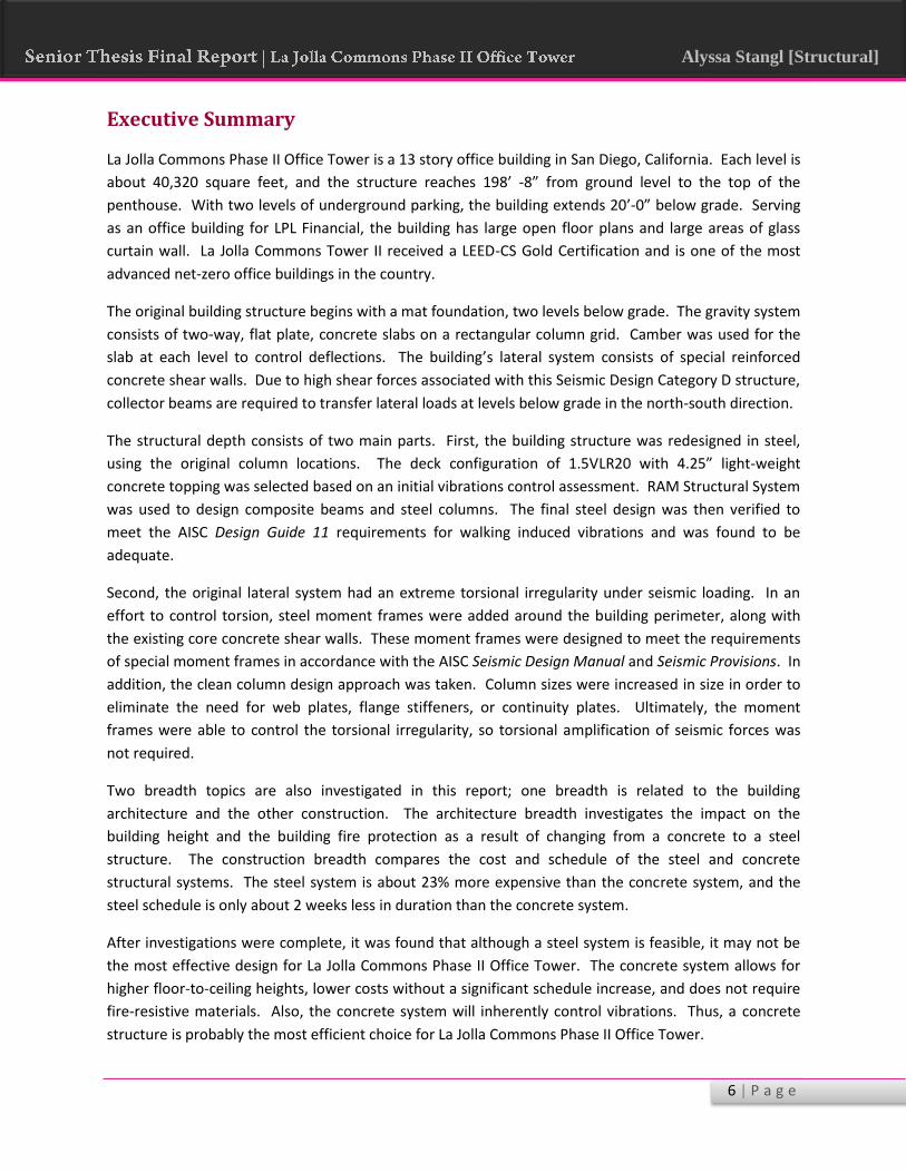
La Jolla Commons Phase II Office Tower is a 13 story office building in San Diego, California. Each level is
about 40,320 square feet, and the structure reaches 198’ -8” from ground level to the top of the
penthouse. With two levels of underground parking, the building extends 20’-0” below grade. Serving
as an office building for LPL Financial, the building has large open floor plans and large areas of glass
curtain wall. La Jolla Commons Tower II received a LEED-CS Gold Certification and is one of the most
advanced net-zero office buildings in the country.
The original building structure begins with a mat foundation, two levels below grade. The gravity system
consists of two-way, flat plate, concrete slabs on a rectangular column grid. Camber was used for the
slab at each level to control deflections. The building’s lateral system consists of special reinforced
concrete shear walls. Due to high shear forces associated with this Seismic Design Category D structure,
collector beams are required to transfer lateral loads at levels below grade in the north-south direction.
The structural depth consists of two main parts. First, the building structure was redesigned in steel,
using the original column locations. The deck configuration of 1.5VLR20 with 4.25” light-weight
concrete topping was selected based on an initial vibrations control assessment. RAM Structural System
was used to design composite beams and steel columns. The final steel design was then verified to
meet the AISC Design Guide 11 requirements for walking induced vibrations and was found to be
adequate.
Second, the original lateral system had an extreme torsional irregularity under seismic loading. In an
effort to control torsion, steel moment frames were added around the building perimeter, along with
the existing core concrete shear walls. These moment frames were designed to meet the requirements
of special moment frames in accordance with the AISC Seismic Design Manual and Seismic Provisions. In
addition, the clean column design approach was taken. Column sizes were increased in size in order to
eliminate the need for web plates, flange stiffeners, or continuity plates. Ultimately, the moment
frames were able to control the torsional irregularity, so torsional amplification of seismic forces was
not required.
Two breadth topics are also investigated in this report; one breadth is related to the building
architecture and the other construction. The architecture breadth investigates the impact on the
building height and the building fire protection as a result of changing from a concrete to a steel
structure. The construction breadth compares the cost and schedule of the steel and concrete
structural systems. The steel system is about 23% more expensive than the concrete system, and the
steel schedule is only about 2 weeks less in duration than the concrete system.
After investigations were complete, it was found that although a steel system is feasible, it may not be
the most effective design for La Jolla Commons Phase II Office Tower. The concrete system allows for
higher floor-to-ceiling heights, lower costs without a significant schedule increase, and does not require
fire-resistive materials. Also, the concrete system will inherently control vibrations. Thus, a concrete
structure is probably the most efficient choice for La Jolla Commons Phase II Office Tower.

7 | P a g e
Alyssa Stangl [Structural]
Chapter 1 – Building Introduction
1.1 – Architectural and Site Overview
La Jolla Commons Phase II Office Tower (LJC II), rendered
in Figure 1.1 – 1, is a high-rise structure located in San
Diego, California. This Seismic Category D structure
reaches 198’-8” above grade with 462,301 square feet of
floor space, including two underground parking levels. LJC
II is a very modern style and open building, featuring flat
plate reinforced slabs on a rectangular column grid. This
creates a very spacious office area for the building tenant,
LPL Financial. LJC II features 13 stories of office space, a
penthouse, and two underground levels of parking.
La Jolla Commons Phase II Office Tower is very similar to
its sister building, Tower I. Although identical in
architectural style, Tower I has a steel structure unlike
Tower II. Figure 1.1 – 2 shows the two towers side by
side, while Tower II is under construction. The two towers
help to unite the La Jolla Commons Campus around a
green space and pedestrian area. Eventually, the campus
will feature two acres of park space, surrounding the
existing and proposed buildings. The campus will also
eventually include a restaurant, bar, spa, gym, and
meeting spaces. A view of the site plan can be viewed in
Figure 1.1 – 3.
LJC II is built underneath a flight path, controlled by the
Federal Aviation Administration (FAA). After negotiations,
the building’s height was limited to its current height of
198’-8”.
After LJC Tower I achieved a LEED-CS Gold rating in 2008,
Tower II was expected to reach a prestigious level of
sustainability as well. LJC II includes features such as
reclaimed water reuse, under-floor air distribution, double pane glazing with low emissivity coating, and
energy efficient lighting systems. Furthermore, LJC II is the first Class A Net-Zero office building in the
United States, and it is the nation’s largest carbon-neutral office building to date. Through methods of
reduced consumption and onsite generation, LJC II will actually return more power to the grid than it
will use annually. LJC II also received a LEED-CS Gold Certification upon structure and shell completion.
See Appendix A for a typical architectural floor plan and two building elevations.
Figure 1.1 - 1 | South East Elevation (Hines & AECOM)
Figure 1.1 - 2 | South East Elevation (Hines & AECOM)
Figure 1.1 - 3 | Building Site Plan (Hines)

8 | P a g e
Alyssa Stangl [Structural]
1.2 – Structural Overview
Structural Framing Summary
La Jolla Commons Tower II is a, cast-in-place concrete structure using mild reinforcing. The foundation
consists of a concrete mat, ranging in thickness from 3 feet to 6.5 feet. The gravity system consists of
two-way, flat plate, reinforced concrete slabs supported by a rectangular grid of reinforced concrete
columns. The lateral system is a series of shear walls located at the building’s core. Also, due to high
seismic loading (seismic category D), the lateral system includes collector beams on the Ground Level
and Lower Level 1, which are used to transmit the earthquake loads from the diaphragm into the shear
walls. The building also features two 15 foot cantilever sections at the North and South ends. The
mechanical penthouse, located on the roof, is framed in steel wide-flanges and hollow structural steel
members with a moment frame acting as the lateral system.
Building Materials
La Jolla Commons Phase II Office Tower, primarily a concrete structure, employs several concrete and
reinforcing types, shown in Table 1.2 – 1 and Table 1.2 – 2, depending on the use in the building.
Although concrete is the main structural material, information regarding steel is provided in Table 1.2 –
3 for the penthouse framing.
Table 1.2 – 1 | Concrete Strengths (at 28 days, 0.5 max cement ratio)
Slab on Grade 3500 PSI Normal Weight Foundations 5000 PSI Normal Weight Shear Walls 6000 or 7000 PSI (per plans) Normal Weight Slabs and Beams 5000 PSI Normal Weight Columns 6000 or 7000 PSI (per plans) Normal Weight Basement Retaining Walls 5000 PSI Normal Weight Cantilever Retaining Walls 5000 PSI Normal Weight Built-up Slabs 4000 PSI Light Weight (110 PCF) All Other Concrete 4000 PSI Normal Weight
Table 1.2 – 2 | Steel Reinforcement
Typical Reinforcing Bars ASTM A-615, Grade 60 Shear Wall and Diaphragm Reinforcing ASTM A-706 Welded Rebar ASTM A-706
Table 1.2 – 3 | Structural Steel
All Structural Steel ASTM A-572, Grade 50 OR ASTM A992 Steel Braced Frame Beams and Columns ASTM A992 Structural Tubing ASTM A-500, Grade B (Fy = 46000 PSI) Structural Piping ASTM A-53, Grade B (Fy = 35,000 PSI)

9 | P a g e
Alyssa Stangl [Structural]
Figure 1.2 – 1 | Mat Foundation Thicknesses - S1L2
Foundation
The foundation system design was provided by Nabih Youssef Associates, the structural consultant for
LJC II, after review of the geotechnical report and recommendations of the geotechnical engineer,
Christian Wheeler Engineering. The final design consisted of a reinforced concrete mat foundation.
Foundation Walls
As stated above in the Building Introduction, La Jolla Commons Tower II has two levels of underground
parking. As a result, concrete foundation walls were utilized around the building perimeter to hold back
soil loads. Typical foundation walls are 14” thick concrete with #7 bars at 12 inches on center (o.c.) at
the exterior and #5 bars at 12 inches o.c. at the inside face, vertical reinforcement. Also, #6 bars at 12
inches o.c. were provided for horizontal reinforcement.
The southeast corner, the area requiring surcharge loading, has 16 inch foundation walls with #9 vertical
bars at 12 inches o.c. (outside face) and #6 bars at 10 inches o.c. (inside face). Also, #6 horizontal bars
were provided at 12inches o.c. The thicker walls are necessary due to increased soil pressures due to
soil saturation.
Mat Foundation Design
The foundation for La Jolla Commons Phase II Office Tower was designed as a reinforced concrete mat
foundation with varying thicknesses and reinforcement. Originally, a system of footings and grade
beams were considered for the foundation. The mat foundation was chosen for several reasons. First,
the large area it covers helps to reduce the soil pressure created by the overturning moment associated
with seismic loads. Second, the construction of one large mat was simply easier than forming all of the
footings and grade beams required for the alternative system. Figure 1.2 – 1 shows the variation in mat
thickness across the foundation.
4’ – 6” Thick 5’ – 6” Thick 6’ – 6” Thick 4’ – 9” Thick 3’ – 0” Thick
NORTH

10 | P a g e
Alyssa Stangl [Structural]
Gravity System
Floor System Overview
La Jolla Commons Tower II is rectangular building that is 315 feet long by 123 feet 8 inches wide. The
building features a flat plate, two-way slab system on a rectangular column grid. As shown in Figure 2.1
– 2, the slab varies in thickness from 10 inches to 14 inches. The exterior edge of the slab at each level is
framed by an 18 inch spandrel beam.
18” Thick Spandrel Beam 10” Thick Core Slab 14” Thick Slab
Reinforcing of the slab varies based on direction and slab thickness. As with the mat foundation, the
floor system has increased sizes and frequency of rebar near the core (where the shear walls are
located). Reinforcing also varies based on column strip and middle strip locations. As required by ACI
318-08, reinforcing for the slab does not exceed a spacing of 18 inches.
Typical bay sizes are 30 feet by 40 feet at the east and west sides of the core. Bay sizes in the core vary
due to shear wall placement. Also, column spacing at the core does not exactly match that of the
exterior columns; however, the largest core bay size is 30 feet by 30 feet. Figure 2.1 – 2 calls out the
two typical bay sizes.
Camber of the structural slabs is used extensively for La Jolla Commons Tower II. Due to the fast
construction of LJC II, construction loads were significant and played a major role in the design.
Designers assumed that the slab would be loaded to the limit during construction, causing cracking. The
slab was then analyzed for creep as a cracked section to determine the worst possible conditions;
deflections were great enough that camber was required. Nabih Youssef Associates consulted
documents such as ACI 435 to determine creep and shrinkage.
Figure 2.1 – 2 | Typical Two Way Slab Thickness Layout – S103
NORTH
Core
Bay
30’x30’
Bay
Typical
Bay
30’x40’

11 | P a g e
Alyssa Stangl [Structural]
Roof System
The roof system for La Jolla Commons Phase II Office Tower is similar to that of the floor system. The
main difference in the gravity system is the introduction of drop panels on the roof system. Drop panels
are utilized on the roof level due to high loads associated with the rooftop mechanical equipment.
Aside from this, the slab is 10 inches thick and features an 18 inch edge beam.
Concrete Columns
The entire gravity system is supported by a series of columns of various sizes on a rectangular column
grid. Column sizes range from a maximum size of 42 inches by 42 inches at Lower Level 2 (lowest level
of the underground parking garage) to a minimum size of 24 inches by 24 inches at the penthouse.
Vertical reinforcing varies significantly based on column height, dimensions, and location. However, all
columns have #5 ties spaced at 4 to 6 inches on center. Minimum requirements from ACI 318-08 (CBC
2010) for spacing and quantity of reinforcement have been met. When the columns were designed,
they were considered fixed when applying only gravity loads to account for any eccentricity in the
loading. However, when the lateral system was designed, the columns were considered pinned. In the
event of an earthquake, the column bases would crack and create a pinned condition; the columns
would, therefore, take minimal lateral load.

12 | P a g e
Alyssa Stangl [Structural]
Lateral System
Shear Walls and Moment Frame
La Jolla Commons Phase II Office Tower has a lateral system of special reinforced concrete shear walls;
moment frames are utilized for the lateral support of the penthouse at the roof cooling tower. All
lateral systems were designed and detailed following Chapter 21 of ACI 318-08 for earthquake loading.
See Figure 1.2 – 3 for the concrete shear wall layout for the lateral force resisting system.
Collector Beams
Collector beams are utilized on Lower Level 1 (upper level of parking) and the Ground Level of LJC II.
Collector beams are used in high seismic areas to transmit earthquake forces into the main lateral
system components. These elements give you the stiffness to transmit the forces through the
diaphragm which cannot efficiently transmit the earthquake loads to the lateral system on its own.
Collector beams mainly run in the north-south direction, except for a few collector beams in the east-
west direction on the Ground Level. Collector elements provide a direct path for the lateral loads from
the diaphragm into the shear walls. This is especially important if the shear walls are not continuous,
are spaced far apart, or are minimal, as is the case with the shear walls in the north-south direction. ACI
318-08 covers the requirements of collector elements in great detail in Section 21.11.
Figure 1.2 – 3 | Typical Shear Wall Layout – S109 NORTH

13 | P a g e
Alyssa Stangl [Structural]
1.3 – Design Codes and Standards
Design Codes and Standards Used in the Original Design
California Building Code 2010
Metal Building Manufacturers Association
o MBMA Recommended Design Practice Manual
American Iron and Steel Institute
o Applicable sections of the AISI Specifications
American Society of Civil Engineering
o ASCE 7-05 (as Adopted by IBC 2009) – Minimum Design Loads for Buildings
American Concrete Institute
o ACI 318 – 08 (as Adopted by IBC 2009) – Building Code Requirements for Structural
Concrete
Design Codes and Standards Used in the Redesign
International Building Code 2012
California Building Code 2013
American Society of Civil Engineering
o ASCE 7-10 – Minimum Design Loads for Buildings
American Concrete Institute
o ACI 318 –11 – Building Code Requirements for Structural Concrete
American Institute of Steel Construction
o Steel Construction Manual, 14th Edition
o Seismic Design Manual and Seismic Provisions
o Design Guide 11: Floor Vibrations Due to Human Activity

14 | P a g e
Alyssa Stangl [Structural]
1.4 – Structural Proposal
Design Scenario
As previously mentioned, La Jolla Commons Phase II Office Tower is a completely concrete structure.
After the investigations in Technical Reports 1 through 4, there are no obvious problems with the
building’s current structural system. Therefore, a scenario has been created in which the building
owner, HINES, would like the structural engineer to design a composite steel structure. The owner
would like the structural engineer to investigate the implications of the steel redesign on the
construction schedule and building cost as compared to the concrete structure. The structural designer
must investigate the potential serviceability issues associated with switching the system from concrete
to steel; the main one to be investigated is vibrations due to human live loading.
It has also been requested by the owner that the lateral system be modified to include steel moment
frames around the building perimeter in addition to the shear walls at the core. The structural engineer
must consider cost and schedule effects of the additional frames and provide a recommendation as to
their effectiveness and feasibility.
Learning Objectives
La Jolla Phase I Office Tower, the building nearly identical to La Jolla Phase II Office Tower, is a steel
structure located right next to LJC II. The building’s lateral system also consists of shear walls at the
core, much like Tower II. Therefore, the design of Tower II in steel is possible and considerably feasible.
One learning objective of this redesign is to investigate both systems and gain a better understanding of
the advantages and disadvantages of a steel versus a concrete gravity system. By considering the effects
of changing the structural system on the schedule, cost, and serviceability conditions, the advantages
and disadvantages of the floor systems can be critically compared from several viewpoints, allowing the
designer to make a more informed decision.
The lateral system for LJC II is special reinforced concrete shear walls. Many of the shear walls are very
thick and require significant reinforcing. In order to learn more about the seismic detailing for steel
moment frames and their efficiency in resisting lateral loads, the incorporation of steel frames as part of
the lateral system will be investigated.
An investigation of structural vibrations due to human live loading will be performed for the steel gravity
system in the office space. This will be done because the spans are quite long for many of the steel
girders, and vibrations are more of a concern with the steel system than the concrete system.
Overall, the goal of this redesign is to develop a better understanding of the design of steel structures
and special steel moment frames and a better understanding of the cost, schedule, and serviceability
considerations for steel versus concrete. Another major goal is to develop a better understanding of the
design of steel structures for seismic loading conditions.

15 | P a g e
Alyssa Stangl [Structural]
Proposed Methods and Solution
The building’s gravity system will be redesigned in composite steel utilizing the same column locations
as the original concrete system, limiting impact on the current building layout and architecture. The
gravity system for the two underground parking levels will remain concrete. Because the gravity system
consists of many members of the same length and loading, beams and girders will be initially designed
by hand to determine appropriate member sizes using the AISC Steel Construction Manual, Fourteenth
Edition. Next, a detailed RAM Steel gravity model will be developed using the dead loads associated
with the new system and the previously determined live loads. The model will aid in the determination
of member adequacy when considering both strength and economy.
As determined in Technical Report 3, the floor system for the proposed redesign will consist of
composite metal deck such as 2 VLI 18 with a 4.5 inch normal-weight concrete topping, total thickness
of 6.5 inches. The girders are expected to reach a maximum depth of 30 inches, and the infill beams are
expected to reach a maximum depth of 14 inches. See Figure 1.4 – 1 for the possible layout for a typical
30 ft x 40 ft bay. In order to limit the overall depth of the system, additional rows of columns may need
to be added at mid-span. However, in order to limit impacts on the original architectural layout of the
space, the original column locations will be investigated first. Different infill beam spacing and layouts
will be investigated to determine the most efficient and “architecturally friendly” system. The columns
will then be designed and tested using the RAM gravity model.
Figure 1.4 – 1 | Potential Steel Framing Layout

16 | P a g e
Alyssa Stangl [Structural]
Once the development of the composite steel gravity system is complete, an analysis of the structure’s
lateral system will be performed. First, the building lateral loads will need to be recalculated using ASCE
7-10. ETABS 2013 will be used to perform a Modal Response Spectrum Analysis on the building’s lateral
system to determine the seismic loads. ETABS 2013 will also be used to generate the building wind
loads. The ETABS 2013 model used in Technical Report 4 will be modified to accurately represent the
shear walls. The model will then be modified to incorporate steel moment frames. A redesign of the
concrete shear walls will need to be performed, and the moment frames will also be designed and
detailed for seismic considerations. Figure 1.4 – 2 shows a potential layout for the added moment
frames.
An investigation of the vibrations associated with human activity on a typical bay of the steel gravity
system will be performed. Calculations will be done by hand, following the provisions of AISC Design
Guide 11: Floor Vibrations Due to Human Activity. These calculations may also be verified, if time
allows, using the RAM Steel model.
Figure 1.4 - 2 | Potential Lateral System Layout

17 | P a g e
Alyssa Stangl [Structural]
MAE Requirements
Graduate level work will be used throughout the design and analysis of the proposed structural system.
AE 530 – Advanced Computer Modeling of Building Structures will be utilized in the creation and
evaluation of both an ETABS lateral model and a RAM Steel gravity model. Because the building is in
SDC D, material from AE 538 – Earthquake Resistant Design for Buildings will be used to design and
detail the building lateral system of concrete shear walls and steel moment frames. Also, additional
work is being done to expand into an area of study not yet learned by the designer: vibrations analysis.
Breadth Studies
Cost and Schedule Analysis
A detailed cost estimate of the proposed structural system will be completed. This cost will then be
compared to that of the existing structural system. In addition, a construction schedule for the
redesigned system will be studied and compared to that of the existing structural system. These
analyses will then be used to determine which system is more economical. RS Means will be used for
most durations and costs; however, information will be requested from the project general contractor.
Architectural/ Fire Protection Analysis
Changing the structure from concrete to steel will have different effects on the building’s architecture.
One item to be investigated is the fire protection of the building structure. Although the structural slab
will provide the 2 hour fire rating between floor levels, steel beams and columns will remain exposed.
As a result, an investigation will be performed on the ceiling system, floor systems, and wall systems to
determine their fire protection adequacy. An analysis on the impact of the structural changes on the
building height will also be performed. The building height is limited due to FAA regulations; therefore,
an analysis on the floor-to-floor heights will be done to determine if a height increase will be necessary.

18 | P a g e
Alyssa Stangl [Structural]
Chapter 2 – Structural Depth
2.1 – Gravity System Design
For this redesign, it was desired to leave the layout and architecture of the spaces as unchanged as
possible. Therefore, the column locations were not changed, and the original grid was used, with
girders spanning between original column locations. Also, the serviceability criteria associated with
vibrations was a major design parameter for the new steel gravity system. Final plans of the gravity
design can be viewed in Appendix B.
Preliminary Vibrations Analysis
Vibrations were a primary concern when redesigning the steel floor system for the office space at La
Jolla Commons. Vibrations can result from walking down a corridor, vibrating equipment, and other
sources. For this particular building, the spans for the bays in the lease space were quite long at about
40 feet. As a result, vibrations due to human excitations could cause noticeable motion for the workers
in the office space.
The design of the gravity system began with a preliminary vibrations analysis following The Preliminary
Assessment for Walking-Induced Vibrations in Office Environments article by Dr. Linda Hanagan and
Taehoo Kim. The procedure outlined in this paper allows the designer to select a slab and deck
configuration and a beam spacing that will produce a suitable floor system for human induced floor
vibrations, according to the criteria of AISC Design Guide 11. This calculation can be done without
having to complete the arduous vibrations calculation outlined in Design Guide 11 for each potential
design.
Using this procedure, many different deck and
framing configurations were considered. After
several iterations, a deck size and slab
thickness was determined. The results of the
preliminary vibrations assessment can be
viewed in Table 2.1 – 1. See Appendix C for a
spreadsheet of all the calculations for the
other design options that were considered. As
can be seen, 1.5VLR20 Composite Deck with
4.25” lightweight topping was selected with
beam spacing at 7’-6” to 8’-0”. This
configuration allows for un-shored construction which has potential for cost and time savings.
Lightweight concrete is desirable for the slab on deck design in order to reduce the building’s seismic
weight; therefore, most designs considered used lightweight concrete. The calculations verifying
strength requirements of the chosen deck can be viewed in Appendix D of this report.
Table 2.1 – 1 | Deck Configuration for Vibration Control
Concrete Strength 3000 psi Steel Grade 50 Deck Type 1.5VLR20 Topping (in) 4.25 LW/NW? LW Total Slab Thickness (in) 5.75 Class from Table 1 4 Select C1 from Table 2 0.413 Select C2 from Table 4 0.019 Evaluate C1 + C2 0.432 C1 + C2 < 0.5? GOOD

19 | P a g e
Alyssa Stangl [Structural]
Gravity System Layout
The next step was to determine whether to span the infill beams in the long or the short direction;
Figure 2.1 – 1 and Figure 2.1 – 2 show a typical bay for each option. It was thought that the shorter
span would be a more economical option because it would yield lighter beams with smaller depths.
However, the option of the beams spanning in the longer direction produced a design that, although
heavier overall, actually required significantly less members for the floor system. It was determined that
the cost of the heavier system was offset by the reduction in time to erect the floor system, mainly
considering crane rental and operations costs. Table 2.1 – 2 shows the weight and the number of
members for each framing option. The table reflects a typical floor from levels 3 to 7. As a result of this
analysis, the long direction layout was chosen as shown in Figure 2.1 – 1.
Table 2.1 – 2 | Infill Beam Comparison for Typical Level 3-7 Layout
Steel Weight (lbs) Number of Members Number of Studs Long Direction 212936 155 3490 Short Direction 179608 225 4489
Also, an additional option for the gravity framing system layout was considered that required an extra
row of columns to break up the long 40 foot span. However, the system created 75% more floor
framing members than the long span option show above in Figure 2.1 – 1, and it only saved a maximum
of three inches in structural depth for each level. This did not seem to be enough of a depth savings to
warrant the interruption of the office layout by adding the row of columns or to add additional time to
the construction schedule. Therefore, this layout was not investigated further.
Figure 2.1 - 1 | Infill Beams Long Direction Figure 2.1 - 2 | Infill Beams Short Direction

20 | P a g e
Alyssa Stangl [Structural]
RAM Structural System – Gravity Model
Next, keeping the constraints for vibrations,
economics, and constructability in mind, a 3D RAM
Structural System model was created to design the
gravity system. Figure 2.1 – 3 shows a 3D view of
the gravity model. Girders span the N-S direction
between columns at the original locations, and the
infill beams span the long E-W direction. 1.5VLR20
deck with 4.25” LW concrete topping is used for all
floor levels. Roof deck was designed to be 1.5B20.
The maximum beam spacing is 7’-6”. See Appendix D
for the deck design calculations. The RAM layout for
a typical level is shown in Figure 2.1-4.
All members were drawn as line elements on the grid system that was used for the concrete system to
limit impact on the architecture and floor layouts. The original shear walls were left in their original
locations, and later moment frames will be added to the perimeter. Shear walls were placed using shell
elements and have been defined as lateral elements using the thicknesses of the original shear walls.
Concrete coupling beams have also been included in this model at the original sizes.
It is also important to note that gravity members will be supported by the existing, load-bearing
concrete shear walls. This connection was modeled as pinned using RAM Structural System. Later in
this report, a suggestion for the connection type will be discussed.
Figure 2.1 - 4 | Framing Layout for a Typical Level NORTH
Figure 2.1 – 3 | 3D View of RAM Gravity Model

21 | P a g e
Alyssa Stangl [Structural]
Gravity Design Loads
Table 2.1 – 3 includes the gravity loads that were applied to the RAM Model for the gravity system
design. The loads include the dead load of the decking, live load, partition loads, wall loads, and
construction loads. Construction loads were used to determine the strength of beams before concrete
cures to allow composite action.
Table 2.1 – 3 | Live and Dead Loads Applied to RAM Model
Location Dead (PSF) Live (including
Partitions) (PSF) Construction Live
Load (PSF) Construction Dead
Load (PSF) Exterior Wall
Load (KLF) Lobby
Around Core 90 100 20 50 n/a
Exit Stairs 90 100 20 50 n/a
Building Core Egress
90 250 20 50 n/a
Restrooms 90 60 20 50 n/a
Lease Space 90 80 20 50 0.118
Location Dead (PSF) Live (including
Partitions) (PSF) Construction Live
Load (PSF) Construction Dead
Load (PSF) Exterior Wall
Load (KLF)
Building Core Egress
90 250 20 50 n/a
Mechanical 90 200 20 50 n/a
Lobby Around Core
90 100 20 50 n/a
Exit Stairs Core
90 100 20 50 n/a
Restrooms 90 60 20 50 n/a
Lease Space 90 80 20 50 0.118
Location Dead (PSF)
Live (including Partitions) (PSF)
Construction Live Load (PSF)
Construction Dead Load (PSF)
Exterior Wall Load (KLF)
Penthouse Area
90 250 20 50 0.1
Roof 23.5 20 n/a n/a n/a
22 | P a g e
Alyssa Stangl [Structural]
Gravity Beam Design
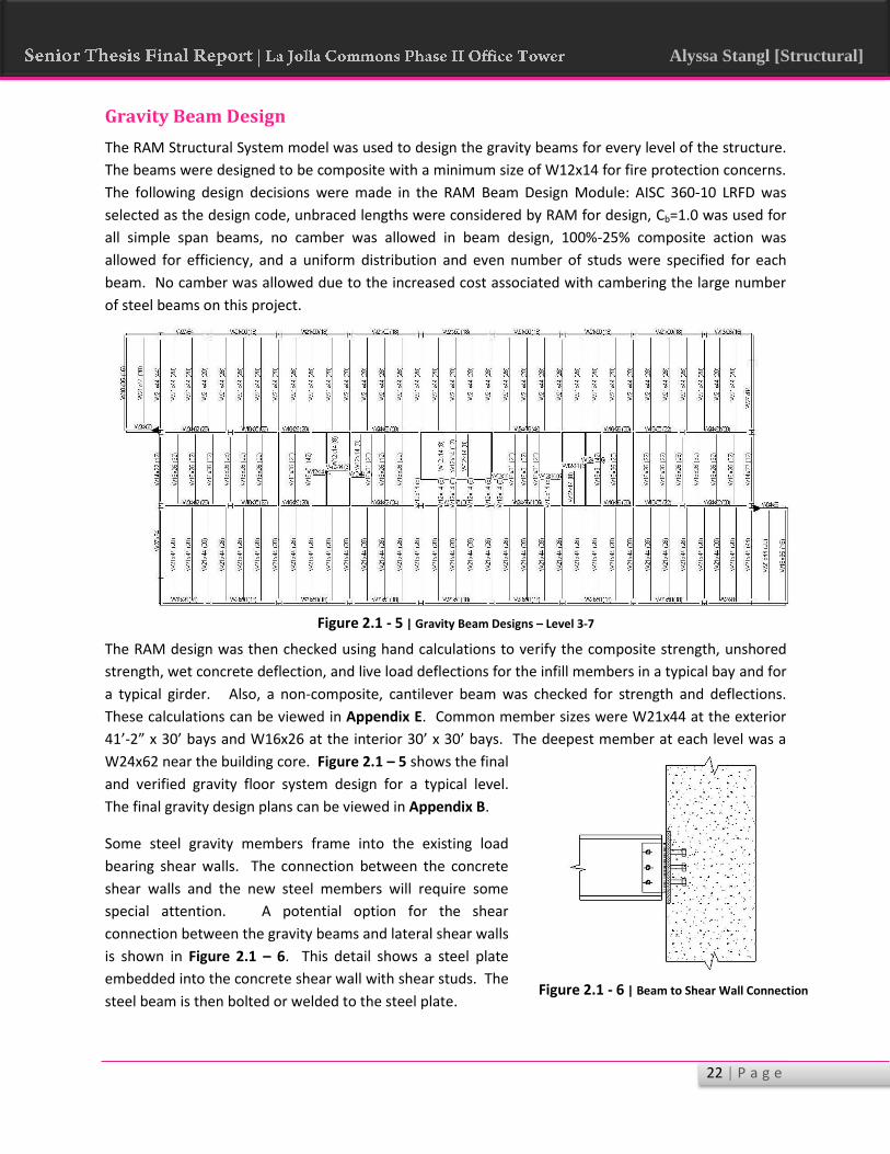
The RAM Structural System model was used to design the gravity beams for every level of the structure.
The beams were designed to be composite with a minimum size of W12x14 for fire protection concerns.
The following design decisions were made in the RAM Beam Design Module: AISC 360-10 LRFD was
selected as the design code, unbraced lengths were considered by RAM for design, Cb=1.0 was used for
all simple span beams, no camber was allowed in beam design, 100%-25% composite action was
allowed for efficiency, and a uniform distribution and even number of studs were specified for each
beam. No camber was allowed due to the increased cost associated with cambering the large number
of steel beams on this project.
The RAM design was then checked using hand calculations to verify the composite strength, unshored
strength, wet concrete deflection, and live load deflections for the infill members in a typical bay and for
a typical girder. Also, a non-composite, cantilever beam was checked for strength and deflections.
These calculations can be viewed in Appendix E. Common member sizes were W21x44 at the exterior
41’-2” x 30’ bays and W16x26 at the interior 30’ x 30’ bays. The deepest member at each level was a
W24x62 near the building core. Figure 2.1 – 5 shows the final
and verified gravity floor system design for a typical level.
The final gravity design plans can be viewed in Appendix B.
Some steel gravity members frame into the existing load
bearing shear walls. The connection between the concrete
shear walls and the new steel members will require some
special attention. A potential option for the shear
connection between the gravity beams and lateral shear walls
is shown in Figure 2.1 – 6. This detail shows a steel plate
embedded into the concrete shear wall with shear studs. The
steel beam is then bolted or welded to the steel plate. Figure 2.1 - 6 | Beam to Shear Wall Connection
Figure 2.1 - 5 | Gravity Beam Designs – Level 3-7

23 | P a g e
Alyssa Stangl [Structural]
Gravity Column Design
RAM Structural System was also used to design the columns under gravity loading. The AISC 360-10
LRFD design code was utilized. Columns were spliced every two stories, this was done for safety reasons
during construction. Also, the length of a two-story column is reasonable to transport at a height of 24
feet. During the design process, the column trial groups were limited to W14, W12, and W10 in order to
maintain a relatively square cross section to limit buckling concerns. The columns were designed using
the gravity loading previously shown in Table 2.1 – 3.
The design of the columns utilized the live load skip loading, provided by the RAM Steel Column module.
This allows the program to determine the worst case loading for the column in order to design the most
effective cross section. Beams that connected into each steel column were assumed to brace the
columns at that location, and, where applicable, the floor system was assumed to brace columns as well.
Gravity columns were optimized to have an interaction below 1.0 in accordance with Equation H1-1a of
the AISC Steel Manual. Also, the design column depth at a particular column location was consistent
over the entire building height. For example, column line Y-7 utilized column sizes W10x33, W10x39,
W10x49, W10x60, and W10x88, the sizes getting heavier as you move down the column line. This helps
to make the splicing of the columns possible.
The column designs ranged widely depending on
the location in the building. The designs of
columns near the center of the building, carrying
more gravity load than exterior columns, ranged
in size from W14x193 to W14x176 at Level 2 of
the building. At the roof level, most column sizes
were found to be W14x43. For lighter loaded
columns near the building perimeter, the column
designs ranged from W10x88 to W12x136 at
Level 2. At roof level, the sizes ranged from
W10x33 to W12x40.
Figure 2.1 – 7 shows a screen shot from the RAM Steel Column module. This image shows the
interaction values of the gravity columns, using a color scale. Orange indicates an interaction between
1.0 and 0.95, yellow indicates 0.90 – 0.95, and so on as the colors get cooler in color. Notice, that the
only blue members, which have an interaction of 0.40 or less, are either the top story columns or
columns in the rigid moment frames. The moment frame columns have been significantly increased to
resist lateral forces, and therefore, the gravity interactions are minimal.
An interior and an exterior column have been hand checked for strength under gravity loads. The
designs produced by RAM are based on a detailed analysis, including P-Delta effects and skip loading.
The hand spot check of columns performed was very simple and only verifies strength under concentric,
axial gravity loading. This was done to make sure that the designs from RAM seemed reasonable
without performing all the arduous calculations. See Appendix E for this rough column hand check.
Figure 2.1 - 7 | RAM Steel Column Module Interactions

24 | P a g e
Alyssa Stangl [Structural]
Final Vibrations Analysis
As mentioned before, vibrations was a primary concern when designing the floor framing system for the
office space. Although vibrations are a serviceability condition, annoying vibrations can impact the
occupants and their productivity in a space. The human response to walking in an office space can vary
based on the magnitude and frequency of the motion, the environment, and the particular person
sensing the motion. Vibrations are a continuous or steady state motion which can often be more
annoying than a single impulse. Vibrations are of particular importance in an office space where
computer monitors and other items can shift on desks and stationary sensors will be more likely to
notice the motion.
A detailed vibration analysis was performed for a typical bay following the procedure described in AISC
Design Guide 11 – Floor Vibrations Due to Human Activity. This was done in order to determine if the
floor design was adequate for human induced floor vibrations to create a more comfortable and
productive work environment. The analysis was done on the typical bay shown in Figure 2.1 – 8. The
bay followed the basic requirements of the Design Guide 11 procedure.
A live load of 11 PSF was assumed as suggested for office spaces by Design Guide 11. Table 4.1 pf DG-11
was used to determine P0, B, and a0/g for the office space. After calculating the combined mode
properties of the beams and girders, the natural frequency of the floor system and the equivalent panel
weight could be determined. This was then used to calculate ap/g to compare to the acceptable a0/g
value from Table 4.1. It was then determined that the bay is acceptable for human induced vibrations
according to AISC Design Guide 11. See Appendix F for the full vibration calculation of a typical bay.
(Equation 2.3 – AISC DG 11)
Figure 2.1 - 8 | Typical Bay Checked for Vibrations Performance
1.5VLR20
4.25” LW Topping

25 | P a g e
Alyssa Stangl [Structural]
2.2 – Lateral System Design
The original lateral system of La Jolla Commons Phase II Office Tower was found to have an extreme
torsional irregularity through Technical Report 4 investigations. In an effort to control the building
torsion, the lateral system was modified to include perimeter moment frames. The frames and existing
shear walls are designed and analyzed according to IBC 2012, ASCE 7-10, ACI 318-11 and AISC-360 LRFD.
Wind and Seismic Loads
Wind and seismic loads were calculated according to ASCE 7-10. Wind and seismic loads were
generated by RAM Frame and were verified using hand calculations. See Table 2.2 – 1 and Table 2.2 – 2
for hand calculated wind and seismic loads, respectively. As expected, seismic loads, even with the
reduced weight of the steel structure, control the lateral design. Figure 2.2 – 1 shows the seismic load
distribution over the building height.
It was determined that, if the torsional irregularity for La Jolla Commons could be eliminated, the
Equivalent Lateral Force Procedure would be allowed to be used to find the design seismic forces.
Because the building exceeds 160 feet, the building period must be less than 3.5Ts in order to use the
ELF Procedure. The building period is 2.74 seconds which is much less than 3.5Ts which is 9.42 seconds.
A Response Modification Coefficient, R, of 6 was used, and a redundancy factor of 1.3 was applied.
These values are for specially reinforced concrete shear walls which will remain part of the lateral force
resisting system. As previously stated, moment frames will be added; however, because the moment
frames do not take 25% or more of the seismic forces, the R value was not increased to 7 for dual
systems. See Table 2.2 – 3 for the verification that a dual system does not exist. Appendix G shows the
hand calculations done based on ASCE 7-05; these hand calculations were then modified using Excel to
update to ASCE 7-10. Figure 2.2 – 2 shows the response spectrum used for the calculation of the new
seismic loads. This information was generated by the USGS online calculator.
Wind Loads
Table 2.2 – 1 | Wind Loads ASCE 7-10
Wind Pressures | North South Wind Pressures | East West
Level Height Force (k) Story Shear (K) Level Height Force (k) Story Shear (K)
Ground 0 44.7 583.31 1 0 23.28 1614.85 2 15 34.61 538.6 2 15 106.06 1591.57 3 28.17 35.2 504 3 28.17 105.68 1485.51
4 41.34 37.14 468.8 4 41.34 110.13 1379.83
5 54.51 38.64 431.66 5 54.51 113.57 1269.7 6 67.68 39.87 393.02 6 67.68 116.4 1156.14 7 80.85 40.93 353.14 7 80.85 118.82 1039.74 8 94.02 41.86 312.21 8 94.02 120.96 920.91 9 107.19 42.7 270.35 9 107.19 122.86 799.96
10 120.36 43.45 227.65 10 120.36 124.59 677.09 11 133.53 44.14 184.2 11 133.53 126.18 552.5 12 146.7 44.78 140.06 12 146.7 127.65 426.32 13 159.87 47.67 95.27 13 159.87 135.53 298.67
PH 173.04 36.29 47.6 PH 173.04 117.03 163.14
PH Roof 198.67 11.31 11.31 PH Roof 198.67 46.11 46.11
Vb = 583 kips Vb= 1615 kip

26 | P a g e
Alyssa Stangl [Structural]
Seismic Loads
Table 2.2 – 2 | Seismic Story Forces ASCE 7-10
T= 1.056 s
k= 1.278 Vb= 4293.3 K
Story Forces Calculation
Level hi (ft) h (ft) W (kip) W*hk Cvx Story Forces Fi (kip)
Penthouse Roof 24.33 198.70 380 328408 0.0158 67.91
Penthouse Floor 14.50 174.37 3735 2734571 0.1317 565.46
13 13.17 159.87 4631 3034717 0.1462 627.52
12 13.17 146.70 4631 2718953 0.1310 562.23
11 13.17 133.53 4631 2410981 0.1161 498.55
10 13.17 120.36 4631 2111350 0.1017 436.59
9 13.17 107.19 4631 1820712 0.0877 376.49
8 13.17 94.02 4631 1539854 0.0742 318.41
7 13.17 80.85 4631 1269753 0.0612 262.56
6 13.17 67.68 4631 1011655 0.0487 209.19
5 13.17 54.51 4631 767221 0.0370 158.65
4 13.17 41.34 4633 539025 0.0260 111.46
3 13.17 28.17 4631 330013 0.0159 68.24
2 15.00 15.00 4569 145491 0.0070 30.08
SUM: 59630 20762706
4293.34
Base Shear = 4293.3 kip
Figure 2.2 - 1 | Seismic Load Distribution

27 | P a g e
Alyssa Stangl [Structural]
Table 2.2 – 3 | Dual System Check
X-Direction Direct Shear
Item Shear (kip) % of Total Shear Dual System?
Frame 1 595.21 18.27% No
Frame 2 643.37 19.74% No
Shear Walls 2020.00 61.99% -
Total Shear 3258.58 kip
Y-Direction Direct Shear
Item Shear (kip) % of Total Shear Dual System?
Frame 3 35.61 1.18% No
Frame 4 32.41 1.08% No
Shear Walls 2941.00 97.74% -
Total Shear 3009.02 kip

28 | P a g e
Alyssa Stangl [Structural]
Figure 2.2 - 2 | Seismic Response Spectrum Information

29 | P a g e
Alyssa Stangl [Structural]
Modeling Considerations and Verification
The lateral system was analyzed and designed using RAM Structural System. The model included the
original special concrete shear walls with additional moment frames around the building perimeter. The
model was used for the analysis and design of the new lateral system.
Load and Model Verification
First, RAM was used to generate the wind and earthquake loads for the building structure; this was done
according to ASCE 7-10. Wind loads were calculated with the mean roof height at the top of the
penthouse level and a Kzt of 1.0. A spreadsheet was created to determine the wind loads, Table 2.2 – 1;
these wind loads were compared to those generated by RAM. The wind loads calculated by hand were
found to be within 3.31% of the values calculated by RAM.
The earthquake forces were also calculated by hand as shown in Table 2.2 – 2. Again, these forces were
then compared to the forces generated by RAM. Seismic loads were found to be within 15% of those
generated by RAM. The loads generated by RAM were ultimately the forces used for the design of the
building structure; however, the difference between the loads calculated by RAM and those calculated
by hand could be due to one or a combination of the following:
- The difference in the approximate period used for the hand calculated ELF method and the
actual building period calculated by RAM
- RAM uses more accurate story masses than the hand calculation, and masses were also updated
as the structural design changed
RAM was used to generate load combinations according to the requirements of ASCE 7-10 and IBC 2012.
A F1 value of 0.5 was used for the live loads. This was done because the building is business use only
and will not be used for public assembly. Also, a redundancy factor of 1.3 was used to increase the
seismic loads. This is a requirement of ASCE 7-10 Section 12.3.4.2 for Seismic Category D structures.
The center of mass and center of rigidity calculated by RAM were then verified using an Excel
spreadsheet. Also, a 2D distribution
of forces was done by hand on level
7 and compared to the RAM load
distribution. All of these
calculations were within a
reasonable percent error of the
values generated by RAM Frame.
See Appendix H for spreadsheets of
these calculations. Table 2.2 – 4
shows the percent error for several
items verified.
Table 2.2 – 4 | Model Verification Summary
% Error X-Direction % Error Y-Direction
Center of Mass 0.284% 1.265%
Center of Rigidity 2.813% 1.681%
Floor Mass 11%
Seismic Loads 15%
Wind Loads 0.25% 3.31%
2D Analysis 10 - 20 %

30 | P a g e
Alyssa Stangl [Structural]
Modeling Considerations
RAM Frame was used for the design of the concrete shear walls and steel moment frames; several
modeling decisions needed to be made before design began. First, each floor diaphragm was modeled
as rigid due to the 4.25” concrete topping on each floor. The roof diaphragm, however, is unfilled metal
deck; therefore, the roof will need to be properly braced to behave as rigid. Because this is a reasonable
addition to the design, the roof diaphragm was also modeled a rigid.
Next, the modeling of the moment frames was performed. According to the AISC Seismic Design
Manual, panel zones must be considered in the design of moment frames; this is due to the significant
increase it can have on lateral drift. As a result, panel zones were considered in the lateral design and
analysis model. Also, P-Delta effects were considered using mass loads; this was done by RAM Frame
using the Direct Analysis Method. RAM generated a B1 factor; however, a B2 factor was not required
because the model was analyzed using P-Delta effects. According to the RAM Frame Manual, when P-
Delta effects are considered in the analysis model, B2 is permitted to be taken as zero.
All moment frame bases were modeled as pinned. This was done because the moment frames will
terminate on a foundation wall with concrete pilasters. This connection would be very difficult to design
to transmit the rotational forces. Therefore, a pinned condition was assigned.
The shear walls were modeled as shell
elements at the thickness of the original
walls. They were modeled as cracked, with
a 65% reduction on the wall stiffness in
bending and shear, as required by ASCE 7-
10 Section 17.7.3. As stated in this code
section, when modeling for seismic design
concrete, shear walls must include the
effects of cracked concrete sections.
According to ACI 318-11 § 8.8, a 65%
reduction in wall stiffness is allowed for
analysis and design purposes. Also,
according to industry professionals, it was
found that it is common practice on the
west coast to crack all shear walls in
accordance with ACI 318-11. The cracked
walls are used for both strength and
serviceability design of the building
structure. This ensures that upon cracking and yielding of rebar in the shear walls, that the other LFRS
elements can handle the increased loading. Also, the shear walls were modeled with a fixed condition
at the base. The walls are tied to the mat foundation, which ranges thickness from 6.5 feet to 4.5 feet,
by hooks at the end of each vertical bar. Therefore, it was decided that a fixed condition was
reasonable. Figure 2.2 – 3 shows the RAM Lateral Model with the gravity system hidden for clarity.
Figure 2.2 - 3 | 3D View RAM Lateral Model – Gravity Hidden

31 | P a g e
Alyssa Stangl [Structural]
The modeling of the core shear walls posed a
challenge. A strange phenomenon was
occuring in the connected shear walls with
respect to torsion; forces were developing in
irregular patterns that did not correspond to
what would be expected based on 2D
analysis. Further investigations were done to
determine if there were problems with the
current modeling technique and to potentially
find a new modeling technique that would
eliminate this problem. It was discovered that
the modeling of intersecting shear walls is a
somewhat controversial topic; many different
methods are used by practicing engineers.
Because of this discrepancy, a modeling
technique suggested by Bentley was selected.
As stated by Bentley Technical Support Group,
“…since RAM Frame assembles the stiffness coefficients of its elements in a 3D fasion, walls that
intersect (and share common nodes) form a 3D system and the 3D behavior is captured by analysis. This
is correct and consisted with finite element analysis.” However, the inclusion of flanges is subject to
wall detailing and limited flange lengths based on ACI 318. Therefore, in order to not account for
flanged behavior that may not exist, a more conservative approach was taken as outlined by Bentley.
Shear walls were disconnected by reducing shear wall lengths by 5 inches at each end. Gravity beams
weret then placied in the gaps to prevent a “framing tables” error in RAM. The gravity member will not
effect the lateral analysis and design of the structure. Using this modeling technique, the flange walls
are not relied upon to resist bending and shear forces out-of-plane. This technique also eliminated the
torsional anomally produced by the connected shear walls. Figure 2.2 – 4 shows this modeling
technique applied to a set of intersecting walls.
The gravity system was included in the lateral model.
This was done partially because RAM Structural
System requires a gravity system to perform any
lateral analysis. However, the AISC Seismic Design
Manual also requires that all gravity loads be
accurately modeled in order to properly account for
second-order effects and to accurately capture the
distribution of gravity load effects on vertical force
resisting members. This can be fulfilled by accurately
modeling the gravity system with the lateral system
in RAM SS. Figure 2.2 – 5 shows the RAM Model
with both lateral and gravity elements. Figure 2.2 - 5 | RAM Lateral Model – Gravity Shown
Figure 2.2 - 4 | Core Wall Modeling Technique

32 | P a g e
Alyssa Stangl [Structural]
The foundation walls and concrete columns below grade were modeled to account for the added
flexibility the two lower levels add to the shear walls. Although a redesign of these elements was not
done, it was important to include the lower levels to obtain an accurate portrayal of the building’s
overall flexibility. Also, it is important to note that the foundation walls in combination with the rigid
diaphragms below grade cause a significant amount of shear reversal in the shear walls at the lower
levels. These forces will not be used for design of the shear walls because they will not be accurate.

33 | P a g e
Alyssa Stangl [Structural]
Lateral System Redesign
Moment Frames
The original lateral system for La Jolla Commons was tested last semester in Technical Report 4. The
building was determined to have an extreme torsional irregularity, which caused an increase in lateral
forces, special detailing requirements, and other complications. It was the goal of this redesign to
eliminate the torsional irregularity by adding moment frames to each façade of the building. The
moment frames were initially designed as ordinary moment frames. They were then optimized for
strength to be classified as a special moment
frames, which require some special seismic
detailing. More information about the
seismic detailing can be found later in this
report. Special moment frames were used
because ASCE 7-10 does not allow
intermediate or ordinary moment frames to
be used on structures taller than 65 feet, for
Seismic Design Category D structures. The
moment frames are placed as indicated in
Figure 2.2 – 6.
As stated above, the effects of cracked concrete sections and panel zones were included in this redesign.
The effects of panel zones were carefully checked using RAM Frame joint analysis. All columns in the
moment frames were designed to be “clean columns.” The clean column option for design was selected
because it has been shown that it is cheaper to increase column sizes than it is to add web plates and
flange stiffeners. This detailing requires significant labor and will increase the project cost and schedule.
According to the article In the Moment by Victor Shneur, PE, “When possible, consider using a deeper
W-Shape to reduce flange forces and possibly eliminate stiffeners at columns. The increase in material
weight is typically offset by eliminating stiffeners and using a less expensive/lighter moment
connection.” The frame joints were verified using RAM to not require web plates or stiffeners, and
panel zone shear capacities were verified. This was done for both the standard steel provisions and for
the seismic provisions of special moment frames. In addition, seismic provisions verified that the
strong-column weak-beam failure mechanism occurs at each joint.
The moment frames were optimized for strength under the controlling load case. The controlling load
case for most frame members is 1.367D + 0.5Lp + 1.3E as generated by RAM Frame. This load
combination includes the effects of vertical earthquake forces, Fv applied to the live load according to
IBC 2012, the over-strength factor of 1.3 for seismic loads, and vertical earthquake forces. Strength
design was done for standard provisions and then refined for special moment frame seismic provisions.
After all strength and joint optimizations were complete, the finals designs are as follows. For the three
bay moment frames, Frames 1 and 2, beams range in size from W24x131 to W24x250, and columns
range in size from W14x233 to W14x500. For the single bay moment frames, Frames 3 and 4, beams
were sized at W14x145, and columns were sized at W14x370. The moment frame detailing will be
discussed later in this report. The final designs of all the moment frames can be found in Appendix I.
Figure 2.2 - 6 | Moment Frame Numbers and Locations

34 | P a g e
Alyssa Stangl [Structural]
Lateral Redesign – Shear Walls
The original thicknesses of the special concrete shear walls were used for the analysis and design of the
new moment frames. Drift limits were checked before shear wall redesign began, and it was found that
the drift values were particularly close to the code limits. As a result, the original wall thicknesses will
not be changed; instead, the reinforcing design will be modified for the new loads.
The existing shear walls were checked under seismic loading from ASCE 7-05 in Technical Report 4;
however, ASCE 7-10 will be used for this redesign, seismic forces are reduced due to a lighter weight
structure, and a more complete list of load combinations has been generated by RAM Frame.
Therefore, a strength verification of the original shear wall designs was performed. Shear Wall U was
selected for this analysis. This was done so that it could be compared to the same check performed on
Shear Wall U under the ASCE 7-05 seismic loads. Figure 2.2 – 7 shows the location of Shear Wall U in
plan. The original design for Shear Wall U is 18 inches thick with #6’s @ 9” horizontally and #6’s @ 12”
vertically, in two curtains.
The strength of this wall was checked at Level 2 under the new seismic loads. This is the first level above
the foundation levels which induce shear reversal; therefore, the shear forces at Level 2 will be accurate.
The wall was found to meet the required strength conditions of ordinary and special reinforced concrete
shear walls in accordance with § 21.9 of ACI 318-11. The reinforcement of the shear walls also meets
the requirements of special reinforced shear walls as outlined in § 21.9.2.1 and § 21.9.2.2 of ACI 318-11.
This verifies that, even under the new concrete code, the existing shear walls can be classified as special.
To view these checks in detail, see Appendix J.
It is important to note that the existing shear wall was found to be “overdesigned” for strength
considerations according to ACI 318-11 under the seismic loads calculated using ASCE 7-10. For
example, ΦVn for the wall was found to be 1534 kip, but, Vu was only found to be 872 kip. Also, the
shear wall was found to no longer require two curtains of reinforcing as the current design specifies.
Shear Wall U
Figure 2.2 - 7 | Location of Shear Wall U

35 | P a g e
Alyssa Stangl [Structural]
As mentioned before, the shear wall thicknesses will not be reduced. Modifications to the shear wall
designs have only been done to the reinforcing. Reducing the thickness of the walls will negatively
affect the building drift, which is already reaching code limits. Therefore, the reinforcing layout was
redesigned to meet the minimum reinforcement ratio, strength, and spacing requirements for special
reinforced shear walls under the new loads. The modified design calls for a single curtain of #6 @ 9”
vertically and #6 @ 9” horizontally. See Appendix J for the design calculations.
A similar design process should be performed for all of the existing shear walls in the building. If it is
desired to reduce the thicknesses of the shear walls, it will be necessary to increase the stiffness of the
moment frames or to design additional moment frames to control building drift under seismic loads.
Collector Beams
Collector beams will still be required at the lower
levels of the building structure, even though the
seismic forces have been reduced. The forces that
must be transmitted to the lateral elements in the
North-South direction are too high for the
diaphragm to direct the loads into the LFRS
elements. The LFRS elements in the North-South
direction are not continuous. In order for them to
work together and share the lateral load based on
relative stiffness, collector elements must be
utilized. As a result, it is recommended that the
existing collector elements be redesigned using ACI
318-11. The collector locations, however, should
not change. See Figure 2.2 – 8 and Figure 2.2 – 9
for the existing collector beam designs and
locations, respectively.
Figure 2.2 - 8 | Original Collector Beam Designs
Figure 2.2 - 9 | Original Collector Beam Locations – LL1
NORTH

36 | P a g e
Alyssa Stangl [Structural]
New Lateral System Drift, Torsion, and Stability Analysis
The next step in the design process was to
verify that the newly modified lateral system
would control the drift and torsional irregularity
associated with La Jolla Commons Phase II
Office Tower under wind and seismic loads. The
stability coefficient, θ, is also verified for each of
the seismic load cases. This verifies the control
of P-delta effects.
Drift Analysis
First, the drift of the building under ASCE 7-10 wind loads was determined using RAM Frame. These
drifts were then checked against H/400, which is and accepted industry standard for wind serviceability.
All applicable wind load cases were analyzed, and the highest resulting deflections were found. As
expected, the wind deflections all met the H/400 industry standard for both the X and Y load cases.
Figure 2.2 – 10 indicates which directions in the model have been labeled as X and Y. The results of the
wind deflection check can be viewed in Table 2.2 – 5.
Table 2.2 – 5 | Wind Displacement Determination
Load Case X - Deflection (in) Y - Deflection (in) L/400 (in) Pass/Fail?
Wind_ASCE710_1_X 1.91 0.00 5.940 Pass
Wind_ASCE710_1_Y 0.00 2.11 5.940 Pass
Wind_ASCE710_2_X+E 1.43 -0.01 5.940 Pass
Wind_ASCE710_2_X-E 1.43 0.01 5.940 Pass
Wind_ASCE710_2_Y+E 0.01 1.68 5.940 Pass
Wind_ASCE710_2_Y-E -0.01 1.49 5.940 Pass
Wind_ASCE710_3_X+Y 1.43 1.58 5.940 Pass
Wind_ASCE710_3_X-Y 1.43 -1.58 5.940 Pass
Wind_ASCE710_4_X+Y_CW 1.07 1.11 5.940 Pass
Wind_ASCE710_4_X+Y_CCW 1.08 1.27 5.940 Pass
Wind_ASCE710_4_X-Y_CW 1.07 -1.26 5.940 Pass
Wind_ASCE710_4_X-Y_CCW 1.08 -1.10 5.940 Pass
Next, drift under seismic loads was determined and checked against the requirements of ASCE 7-10 §
12.8.6. Using Table 12.12-1 of ASCE 7-10, it was determined that for La Jolla Commons the story drift
limit is 0.020hsx. The elastic story drift taken from RAM Frame was modified as required by equation
12.12-15 of ASCE 7-10, where Cd = 5 for special concrete shear walls with special moment frames (not
behaving as a dual system). Figure 2.2 – 11 shows the method used to determine drift values, using
ASCE 7-10 § 12.8.6.
Figure 2.2 - 10 | X and Y Direction Definition

37 | P a g e
Alyssa Stangl [Structural]
The controlling load case for drift in the X-direction was found to be EX + EXT (x-direction seismic forces
with 5% eccentricity). The controlling case in the Y-direction was EY + EYT (y-direction seismic forces
with 5% eccentricity). As can be seen in Table 2.2 – 6, the amplified story drifts were all found to be
within the allowable drift limits. The overall building deflection in the X-direction under the controlling
load case was found to be 36.32 inches. The overall building deflection in the Y-direction under the
controlling load case was found to be 12.46 inches. The story drifts can be viewed below.
Table 2.2 – 6 | Seismic Story Drift Check
Level Level Height (ft) Cd*δx Allowable Drift
(in)
Pass/Fail?
X-Direction Y-Direction X-Direction Y-Direction
PH Roof 24.33 5.15 2.04 5.839 Pass Pass
PH 14.5 3.08 1.22 3.480 Pass Pass
13 14 2.83 1.02 3.360 Pass Pass
12 14 2.87 1.01 3.360 Pass Pass
11 14 2.89 1.00 3.360 Pass Pass
10 14 2.89 0.97 3.360 Pass Pass
9 14 2.85 0.93 3.360 Pass Pass
8 14 2.76 0.88 3.360 Pass Pass
7 14 2.62 0.82 3.360 Pass Pass
6 14 2.41 0.74 3.360 Pass Pass
5 14 2.13 0.64 3.360 Pass Pass
4 14 1.76 0.53 3.360 Pass Pass
3 14 1.29 0.40 3.360 Pass Pass
2 15 0.78 0.27 3.600 Pass Pass
Overall Displacement= 36.32 12.46
Figure 2.2 - 11 | Story Drift Determination – ASCE 7-10 Figure 12.8-2

38 | P a g e
Alyssa Stangl [Structural]
Torsional Analysis
The next item to be checked was the torsional properties of the building structure under seismic loads.
As previously mentioned, the main purpose of the new moment frames was to control the torsional
irregularity associated with the original lateral system. As defined by Table 12.3-1 of ASCE 7-10, there
are two types of torsional irregularities – regular and extreme. The formal definition of each of these
horizontal structural irregularities can be viewed in Figure 2.2 – 12.
The torsional analysis was done using two points at either end of the structure – Point A and Point B as
shown in Figure 2.2 – 13. These two points were then used to calculate δavg and δmax, which were
compared to determine if a torsional irregularity or an extreme torsional irregularity existed for both the
X and Y directions. It was determined that neither existed in the new structure, in neither the X nor Y
direction. See Table 2.2 – 7 for the analysis performed in the X-direction and Table 2.2 – 8 for the Y-
direction.
Figure 2.2 - 12 | Horizontal Structural Irregularities – ASCE 7-10 Table 12.3-1
Figure 2.2 - 13 | Points A and B Required for Torsional Analysis

39 | P a g e
Alyssa Stangl [Structural]
Table 2.2 – 7 | Check for Torsional Irregularities X Direction
Level δA δB δavg δmax Does a torsional
irregularity exist?
PH 0.6268 0.6269 0.63 0.6269 No
Level 13 0.5762 0.5764 0.58 0.5764 No
Level 12 0.5846 0.5847 0.58 0.5847 No
Level 11 0.5887 0.5888 0.59 0.5888 No
Level 10 0.5877 0.5878 0.59 0.5878 No
Level 9 0.5788 0.5789 0.58 0.5789 No
Level 8 0.5614 0.5615 0.56 0.5615 No
Level 7 0.5320 0.5321 0.53 0.5321 No
Level 6 0.4901 0.4902 0.49 0.4902 No
Level 5 0.4330 0.4331 0.43 0.4331 No
Level 4 0.3582 0.3582 0.36 0.3582 No
Level 3 0.2116 0.2637 0.24 0.2637 No
Table 2.2 – 8 | Check for Torsional Irregularities Y Direction
Level δA δB δavg δmax Does a torsional
irregularity exist?
PH 0.3206 0.3086 0.31 0.32 No
Level 13 0.2910 0.2809 0.29 0.29 No
Level 12 0.2891 0.2800 0.28 0.29 No
Level 11 0.2847 0.2767 0.28 0.28 No
Level 10 0.2771 0.2702 0.27 0.28 No
Level 9 0.2657 0.2599 0.26 0.27 No
Level 8 0.2513 0.2470 0.25 0.25 No
Level 7 0.2329 0.2300 0.23 0.23 No
Level 6 0.2101 0.2084 0.21 0.21 No
Level 5 0.1826 0.1820 0.18 0.18 No
Level 4 0.1505 0.1506 0.15 0.15 No
Level 3 0.1280 0.1139 0.12 0.13 No
This analysis verifies that the additional perimeter moment frames were able to control the torsional
irregularity associated with the original building structure. The frames are stiff enough to resist enough
torsional shears to limit the building rotation. The frames are also a significant distance away from the
center of rigidity to help control torsional effects. Therefore, it can be said that the frames were useful
in controlling the torsional irregularities and eliminate the need to amplify the seismic forces.

40 | P a g e
Alyssa Stangl [Structural]
Stability Coefficient Analysis
P-delta effects can have a major impact on moment frame design. Although RAM Structural System will
verify that P-delta effects are under control, the stability coefficient was analyzed to verify that the P-
delta effects were properly accounted for.
The stability coefficient was calculated as required by ASCE 7-10 § 12.8.7. The stability coefficient is
calculated using Equation 12.8-16 below and is then compared to the maximum allowable value found
using Equation 12.8-17 below. In these equations, Cd = 5 and β = 1.0.
These values were then compared using an Excel spreadsheet. All stability coefficients were found to be
below the maximum allowed values for all applicable load combinations. Table 2.2 – 9 shows a sample
of the stability coefficient comparison table for one load case.
Table 2.2 – 9 | ASCE 7-10 Stability Coefficients
RAM Frame
LOAD CASE: ELF EQ
Type : EQ_ASCE710_X_+E_F
Level θx θy θx/(1+θx) θy/(1+θy) θx max θy max θx Ok? θx Ok?
Roof 0.092 0 0.084 0 0.1 0.1 Pass Pass
PH 0.07 0 0.065 0 0.1 0.1 Pass Pass
Level 13 0.072 0 0.067 0 0.1 0.1 Pass Pass
Level 12 0.077 0 0.072 0 0.1 0.1 Pass Pass
Level 11 0.082 0 0.076 0 0.1 0.1 Pass Pass
Level 10 0.088 0 0.081 0 0.1 0.1 Pass Pass
Level 9 0.093 0 0.085 0 0.1 0.1 Pass Pass
Level 8 0.095 0 0.086 0 0.1 0.1 Pass Pass
Level 7 0.097 0 0.088 0 0.1 0.1 Pass Pass
Level 6 0.097 0 0.088 0 0.1 0.1 Pass Pass
Level 5 0.093 0 0.085 0 0.1 0.1 Pass Pass
Level 4 0.084 0 0.078 0 0.1 0.1 Pass Pass
Level 3 0.068 0 0.064 0 0.1 0.1 Pass Pass
Level 2 0.038 0 0.036 0 0.1 0.1 Pass Pass
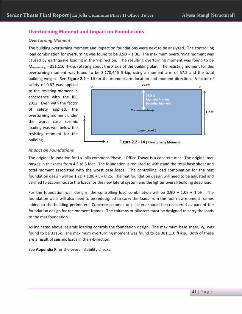
41 | P a g e
Alyssa Stangl [Structural]
Overturning Moment and Impact on Foundations
Overturning Moment
The building overturning moment and impact on foundations were next to be analyzed. The controlling
load combination for overturning was found to be 0.9D + 1.0E. The maximum overturning moment was
caused by earthquake loading in the Y-Direction. The resulting overturning moment was found to be
Moverturning = 381,110 ft-kip, rotating about the X axis of the building plan. The resisting moment for this
overturning moment was found to be 3,170,446 ft-kip, using a moment arm of 57.5 and the total
building weight. See Figure 2.2 – 14 for the moment arm location and moment direction. A factor of
safety of 0.67 was applied
to the resisting moment in
accordance with the IBC
2012. Even with the factor
of safety applied, the
overturning moment under
the worst case seismic
loading was well below the
resisting moment for the
building.
Impact on Foundations
The original foundation for La Jolla commons Phase II Office Tower is a concrete mat. The original mat
ranges in thickness from 4.5 to 6 feet. The foundation is required to withstand the total base shear and
total moment associated with the worst case loads. The controlling load combination for the mat
foundation design will be 1.2D + 1.0E + L + 0.2S. The mat foundation design will need to be adjusted and
verified to accommodate the loads for the new lateral system and the lighter overall building dead load.
For the foundation wall designs, the controlling load combination will be 0.9D + 1.0E + 1.6H. The
foundation walls will also need to be redesigned to carry the loads from the four new moment frames
added to the building perimeter. Concrete columns or pilasters should be considered as part of the
foundation design for the moment frames. The columns or pilasters must be designed to carry the loads
to the mat foundation.
As indicated above, seismic loading controls the foundation design. The maximum base shear, Vb, was
found to be 3216k. The maximum overturning moment was found to be 381,110 ft-kip. Both of these
are a result of seismic loads in the Y-Direction.
See Appendix K for the overall stability checks.
Figure 2.2 - 14 | Overturning Moment

42 | P a g e
Alyssa Stangl [Structural]
Figure 2.2 - 15 | SMF Inelastic Deformation Zones
Special Moment Frame Detailing
Moment frames have been designed to help resist torsional forces due to earthquake loading. It has
been determined that the moment frames must be detailed as special moment frames. Although the
frames do not allow the lateral system to be considered dual system in either direction, the moment
frames are required to be special by ASCE 7-10 § 12.2.5.5. Intermediate and ordinary moment frames
are only allowed to be used in SDC D when the overall building height is no more than 65 feet – La Jolla
Commons is 198 feet tall. As a result, the moment frames were designed under the Special Moment
Frame Seismic Provisions in RAM Frame, with the columns designed as clean columns. However,
additional detailing is required for these moment frames and some of the requirements investigated by
RAM Frame will also be discussed.
Special moment frames (SMF) derive their ductility during a seismic event through the flexural yielding
of beams, the shear yielding of column panel zones, and the flexural yielding of columns. They allow for
high ductility as well as architectural versatility. The lateral displacement is controlled by the flexural
stiffness of the framing members and the ability of frame joints to resist rotation. As can be seen from
the frame designs in Appendix I, many of the framing members are the same size as members below
them. This is because SMF are often sized for drift and rotation control rather than strength provisions.
When designing the beam to column connections,
it is important to size members or detail
connections to promote inelasticity in the beams
and the panel zone, as shown in Figure 2.2 – 15.
Section K2 of the AISC Seismic Provisions requires
that at least 75% of the frame deformation must
occur at beam hinge locations. This can be done
through the use of continuity plates, doubler
plates, and increasing the column sizes to
encourage hinging away from the column face. As
stated by Section 4.3 of the AISC Seismic Design
Manual, there are two common methods used to
force plastic hinging of the beam away from the
column face. One way is to specially detail the
column-to-beam connection to create enough toughness in the connection to force the elasticity into
the beam. Another method is to use a reduced beam section (RBS) connection a short distance away
from the column face. The reduced beam section properties will force yielding to occur at this location.
There are two different ways to design for panel zone behaviors in SMF. Generally strong or balanced
panel zones are required. In a strong panel zone, the panel strength is greater than the surrounding
framing members so that most of the inelastic deformation occurs in the members. A balanced panel
allow for a similar inelastic deformation in both the panel zone and the surrounding framing members.
AISC Seismic Provisions leads to the design of SMF that behave as either strong or balanced panel.
Weak panel designs are possible but are allowed only in intermediate and ordinary moment frames.

43 | P a g e
Alyssa Stangl [Structural]
One of the most important details of SMF design is the strong column-weak beam concept. The AISC
Seismic Provisions requires the following equation to be true:
∑
∑
∑ refers to the combined flexural strengths of all the columns coming into a particular joint. ∑
refers to that of the beams coming into the same joint at the plastic hinge locations. The goal of this
provision is not to eliminate column yielding; the idea is to eliminate the development of a story
mechanism which would cause an entire
story to collapse. Beam mechanisms, forced
by strong column-weak beam configurations
are the preferred mechanism. Figure 2.2 –
16 illustrates these mechanisms.
This was a factor that was verified by the
RAM Frame Seismic Joint checks and seismic
strength checks. A few joints were also spot
checked to verify that this condition is met.
All frames will experience strong column –
weak beam behavior, not story mechanism
behavior, as required by AISC Seismic
Provisions § E3.2.
SMF are required by AISC to meet the requirements for highly ductile members. Therefore, stability
bracing of beams must satisfy the requirements for highly ductile members in section D1.2b of the AISC
Seismic Provisions. There are requirements for the lateral bracing of the entire beam length and
additional requirements for plastic hinge locations. Some provisions are as follows: (1) Both flanges of
beams shall be laterally braced or the beam cross section shall be torsionally braced, (2) Bracing of
highly ductile beam members shall have a maximum spacing of ⁄ . Additional special
bracing at plastic hinge locations must meet the requirements of Section D.2c. This section lists the
requirements for the spacing and required strength of the lateral bracing of the plastic hinge regions.
Each of these items was verified using the RAM Frame Module on SMF Seismic Provision analysis.
Additional requirements for highly ductile members in SMF are as follows. One such provision is that
members shall have flanges continuously connected to the web or webs. Members must also not
exceed the width-to-thickness ratios listed in Table D1.1 in the AISC Seismic Provisions. For example, for
I-shaped sections the maximum width-to-thickness ratio, √ ⁄ , must not be exceeded by
any member. There are different limiting ratios for different section types. This provision was verified
by RAM Frame. Furthermore, no abrupt changes in beam flange area are allowed in plastic hinge
regions as well as no flange holes or drilling. These changes will make the determination of the plastic
behavior too unpredictable.
Figure 2.2 - 16 | Story vs. Beam Mechanism

44 | P a g e
Alyssa Stangl [Structural]
Connection design is the next item that requires special detailing. First, groove welds at column splices,
welds at column-to-base plate connections, and complete-joint-penetration groove welds of beam
flanges and beam webs to columns are must meet the requirements of Section A3.4b of the AISC
Seismic Provisions. This section lists the mechanical properties of the filler metals for these welds,
including required yield and tensile strengths. Beam-to-column connections for seismic force resisting
systems (SFRS) are required to accommodate a story drift angle of at least 0.04 radians. Also, the
flexural resistance of the connection must be at least 0.8Mp of the connected beam at the 0.04 radian
story drift angle. In addition, the connections must be proven to conform to the requirements of
Section E3.6b by either conforming to a prequalified connection or through performance testing.
Connections are also responsible for handling the shears occurring at column panel zones as shown in
Figure 2.2 – 15. The shear strength of the panel zone is calculated from the sum of the moments at the
column faces. The design shear strength is required to be , where = 1.0 for LRFD design.
The AISC Seismic Provisions also includes
specific requirements for the inclusion of
doubler plates to increase panel zone
thicknesses to meet shear requirements;
however, the design of the new special
moment frames for La Jolla Commons did
not include doubler plates because column
sizes were increased until the column web
thickness met the shear strength
requirements of Section E3.5e. However, a
comparison of the clean column option
versus a doubler plate design is shown in Figure 2.2 – 17. This section shows a symmetrical doubler
plate layout with fillet welds as required by Section E3.6e (3).
Continuity plates are another common item used in detailing of SMF. Yet again, the moment frames for
La Jolla Commons were designed to not require continuity plates. This is possible when the beam flange
is welded to a wide-flange column, if the column is of sufficient thickness, as determined by Equations
E3-8 and E3-9 in the AISC Steel Seismic Provisions. Although
continuity plates were not required for the design of the
moment frames for this project, Figure 2.2 – 18 shows what the
continuity plate detail would look like if required.
The final item to be addressed is column splicing. As was
discussed previously in this report, the columns in the new steel
redesign are spliced every two stories. RAM Frame does not
analyze columns splices or connections so these would need to
be designed and detailed separately. According to the AISC
Seismic Provisions, when welds are used to make a splice, they
must be complete-joint-penetration groove welds. Bolted connections are permitted but the
connection must meet specific flexural and shear strength requirements of Section E3.6g.
Figure 2.2 - 18 | Continuity Plate Detail
Figure 2.2 - 17 | Clean Column vs Doubler Plate

45 | P a g e
Alyssa Stangl [Structural]
2.3 – MAE Requirements
Graduate level coursework was used throughout the design and analysis of the new structural system.
AE 530 – Advanced Computer Modeling of Building Structures was utilized in the creation and
verification of a RAM Structural System gravity and lateral model. Also, material from AE 538 –
Earthquake Resistant Design for Buildings was used to design and determine required detailing for the
new steel moment frames, as well as, the verification and design modification of the original shear walls.
In addition, an investigation was done on the vibrations of the new steel floor system. This required
expansion of knowledge beyond completed undergraduate and graduate coursework.
AE 538 – Earthquake Resistant Design for Buildings
“The objective of this course is to provide students with an understanding of damaging aspects
of earthquake phenomenon and how to analyze and design buildings to satisfy model building
code provisions.” – Penn State Department of Architectural Engineering
AE 530 – Advanced Computer Modeling of Building Structures
“The course is designed to provide students with the ability to create computer models
representative of actual building response and in line with prevalent modeling techniques
implemented using commercial structural analysis software. Primary objectives include
developing an understanding of the process used by computers to solve structural systems, with
emphasis placed on the use of computer models in the analysis and design process to satisfy
building code requirements.” – Penn State Department of Architectural Engineering

46 | P a g e
Alyssa Stangl [Structural]
Chapter 3 – Architectural Breadth The architecture of La Jolla Commons will be impacted by the change in building structure from concrete
to steel. Although the original column and wall locations were maintained, the building height will be
impacted along with the building fire protection requirements. The chapter of the report analyzes the
building height impact. It also looks into the fire protection requirements for the new structure.
Designs for the required fire-resistance ratings have also been determined.
3.1 – Floor-to-Ceiling Height and Building Height Analysis
The change from a concrete structure to a steel structure will have a significant impact on the overall
height of the building. La Jolla Commons Phase II Office Tower’s current height is 198’-8”, which is
firmly restricted by a flight path controlled by the Federal Aviation Administration. As a result, an
increase in building height would be unacceptable. As expected, the steel structure was, on average,
about 15 inches deeper per level than the original concrete flat plate slab. Two options are to be
considered. Either the original building height will be maintained and the floor-to-ceiling heights will
decrease, or the original floor-to-ceiling heights will be maintained, causing the building height to
increase, ignoring the height restriction. Table 3.1 – 1 shows a comparison of the depth of the structure
at each level for the concrete and steel systems, and Table 3.1 – 2 shows the difference in the
cumulative floor depths of the two systems.
Table 3.1 – 1 | Structural Depths
Level Deepest Member
Depth of Deepest Member (in)
Total Slab Depth (in)
Depth of Structure at Level (in)
Original Depth of Structure (in)
2 W24x76 23.9 5.75 29.65 14
3 W24x76 23.9 5.75 29.65 14
4 W24x76 23.9 5.75 29.65 14
5 W24x76 23.9 5.75 29.65 14
6 W24x76 23.9 5.75 29.65 14
7 W24x76 23.9 5.75 29.65 14
8 W24x76 23.9 5.75 29.65 14
9 W24x84 24.1 5.75 29.85 14
10 W24x84 24.1 5.75 29.85 14
11 W24x84 24.1 5.75 29.85 14
12 W24x84 24.1 5.75 29.85 14
13 W24x84 24.1 5.75 29.85 14
PH W24x62 23.7 5.75 29.45 14
Roof W16x26 15.7 5.75 21.45 14
Table 3.1 –2 | Cumulative Structural Floor Depths
Concrete Floor Structure Total Depth 196 in Steel Floor Structure Total Depth 407.7 in
Difference in Structural Depth 211.7 in 17.64 ft

47 | P a g e
Alyssa Stangl [Structural]
It obviously is unfavorable to increase the overall height of the building to maintain ceiling heights;
therefore, an analysis was done to determine the impact of the decreased ceiling heights. The office
space finishes are unknown; however, typical office conditions were assumed for this analysis. A drop
ceiling was assumed. Also, it is known that there is a 12 inch raised floor system on each level of the
building’s lease space; the raised floor creates a plenum for the under-floor air distribution system. For
the original concrete building structure, it was assumed that the drop ceiling hung 18 inches below the
slab in order to conceal concrete beams. For the redesigned steel structure, the ceiling is assumed to
hang 36 inches below the structural slab in order to conceal the floor structure. The raised floor-to-
ceiling heights for the steel and concrete structures are compared in Table 3.1 – 3 and Table 3.1 – 4
respectively, assuming the original building height of 198 feet is to be maintained.
Table 3.1-3 | Steel Floor System - Building Height at 198 ft
Story Original Floor To Floor Height (ft)
Raised Floor System (in)
Depth of Floor Structure (in)
Drop Ceiling Required to Enclose Structure (in)
Floor to Ceiling Height (ft)
2 15.00 12.0 29.7 36.0 9.17
3 13.17 12.0 29.7 36.0 11.00
4 13.17 12.0 29.7 36.0 9.17
5 13.17 12.0 29.7 36.0 9.17
6 13.17 12.0 29.7 36.0 9.17
7 13.17 12.0 29.7 36.0 9.17
8 13.17 12.0 29.7 36.0 9.17
9 13.17 12.0 29.9 36.0 9.17
10 13.17 12.0 29.9 36.0 9.17
11 13.17 12.0 29.9 36.0 9.17
12 13.17 12.0 29.9 36.0 9.17
13 13.17 12.0 29.9 36.0 9.17
Penthouse 14.50 0.0 29.5 0.0 14.50
Roof 24.33 0.0 21.5 0.0 24.33

48 | P a g e
Alyssa Stangl [Structural]
Table 3.1-4 | Original Concrete Floor System - Building Height at 198 ft
Level Original Floor To Floor Height (ft)
Raised Floor System (in)
Depth of Floor Structure (in)
Drop Ceiling Required to Enclose Structure (in)
Floor to Ceiling Height (ft)
2 15.00 12.0 14.0 18.0 12.50
3 13.17 12.0 14.0 18.0 10.67
4 13.17 12.0 14.0 18.0 10.67
5 13.17 12.0 14.0 18.0 10.67
6 13.17 12.0 14.0 18.0 10.67
7 13.17 12.0 14.0 18.0 10.67
8 13.17 12.0 14.0 18.0 10.67
9 13.17 12.0 14.0 18.0 10.67
10 13.17 12.0 14.0 18.0 10.67
11 13.17 12.0 14.0 18.0 10.67
12 13.17 12.0 14.0 18.0 10.67
13 13.17 12.0 14.0 18.0 10.67
Penthouse 14.50 0.0 14.0 0.0 14.50
Penthouse Roof 24.33 0.0 14.0 0.0 24.33
As can be seen, the original floor-to-ceiling height is 10’-8”, and the new floor-to-ceiling height is 9’-2” in
the office space. Figure 3.1 – 1 shows the differences between the original concrete system and new
steel system floor-to-ceiling heights.
Concrete System Steel System
Figure 3.1 – 1 | Floor-to-Ceiling Heights – Concrete vs. Steel

49 | P a g e
Alyssa Stangl [Structural]
Next, using the floor-to-ceiling heights of the original concrete structure, the new required floor-to-floor
heights were determined for the steel structure. In order to maintain the original floor-to-ceiling
heights, the building’s overall height must increase from 198’-8” to 216’-8”. This is an increase in the
overall building height of 18’-0”. Table 3.1 – 5 shows this calculation.
Table 3.1-5 | Steel Floor System – Original Floor to Ceiling Heights maintained
Level Raised Floor To Ceiling Height Required (ft)
Raised Floor
System (in)
Depth of Floor Structure (in)
Drop Ceiling Required to Enclose Structure (in)
New Floor to Floor Height
(ft)
2 12.5 12.0 29.7 36.0 16.5
3 10.7 12.0 29.7 36.0 14.7
4 10.7 12.0 29.7 36.0 14.7
5 10.7 12.0 29.7 36.0 14.7
6 10.7 12.0 29.7 36.0 14.7
7 10.7 12.0 29.7 36.0 14.7
8 10.7 12.0 29.7 36.0 14.7
9 10.7 12.0 29.9 36.0 14.7
10 10.7 12.0 29.9 36.0 14.7
11 10.7 12.0 29.9 36.0 14.7
12 10.7 12.0 29.9 36.0 14.7
13 10.7 12.0 29.9 36.0 14.7
Penthouse 14.5 0.0 29.5 0.0 14.5
PH Roof 24.3 0.0 21.5 0.0 24.3
New Building Height 216.7
Original Building Height 198.7
Increase in Building Height 18.00
As a result of this significant increase in building height, it has been decided that the original building
height should be maintained in order to agree with the FAA height restriction. Although the floor-to-
ceiling heights will decrease to 9’-2” in the office spaces, this is not a significant architectural change or
concern. According to several design guides and industry standards, office spaces typically have a floor-
to-ceiling height of 8’-6” to 9’-0”. Therefore, the office space, following precedent office buildings, will
still maintain a comfortable and functional atmosphere.

50 | P a g e
Alyssa Stangl [Structural]
3.2 – Fire Protection Analysis and Design
General Information
La Jolla Commons Phase II Office Tower was originally an entirely concrete structure; as such, the
structure had inherent fire-resistive abilities. Changing the building structure to steel has the
disadvantage of requiring some sort of fire protection for the building’s structural elements. An analysis
of IBC 2012 has been performed to determine the requirements for the new structure’s fire protection.
Also, designs for the fire protection of the building elements have been selected and illustrated, utilizing
the Underwriter Laboratories’ approved fire protection details. The original building design featured a
full automatic sprinkler system. This system will remain in the new building design.
The first step in the analysis was to determine the requirements for the fire protection of the structural
elements based on the
building height and use. The
Use and Occupancy
Classification is Business
Group B, which is defined as
typical office buildings. As
shown in Figure 3.2 – 1, in
order to construct a 13 story,
198 foot tall, and 32,085
square foot per story office
building, Type 1A construction
must be utilized, according to
Table 503 of IBC 2012.
However, according to Section
403.2.2.1, because the height
of LJC II is less than 420 feet,
the fire resistance ratings of
the building elements in Type
1A construction are able to be
reduced to the minimum fire
ratings for the building
elements in Type 1B. This
excludes columns which will
remain Type 1A construction.
According to Table 601 of IBC 2012, shown in Figure 3.2 – 2, the required fire-resistance rating for the
primary structural elements of Type 1A construction is 3 hours. For Type 1B construction, the rating is 2
hours. Therefore, the columns will be Type 1A construction and will, therefore, require a 3 hour rating.
The floor framing members will require a 2 hour rating in accordance with Type 1B construction. Table
3.2 – 1 shows the summary of the required fire-ratings for the structural members.
Figure 3.2 - 1 | Required Construction Types, IBC 2012 Table 503

51 | P a g e
Alyssa Stangl [Structural]
Table 3.2 – 1 | Required Fire-Resistance Ratings
Element Construction Type Required Rating (hours)
Primary Floor Framing Members Type 1B 2 Secondary Floor Framing Members Type 1B 2 Structural Columns Type 1A 3
Designs were selected based on these requirements as well as those of IBC 2012 Section 704. Columns
must be individually encased on all four sides for the full column length. This includes the connections
to other structural members. When the column extends through the ceiling, the encasement must be
continuous from the floor assembly below through the ceiling space to the top of the column. For floor
framing members, all members are required to have individual encasement on all sides for the full
length of the member. This again includes the connections to other members.
Figure 3.2 - 2 | Fire Resistance Ratings for Building Elements, IBC 2012 Table 601

52 | P a g e
Alyssa Stangl [Structural]
Floor Framing Fire Protection Design
Very little is known about the interior architecture and finishes of La Jolla Commons. The interior build
out information is held by LPL Financial and are confidential. Therefore, in order to create the most
conservative design that will work with all finishes, the ceiling materials were assumed to not create an
adequate fire-resistance rating for the floor framing members. Therefore, other means of protection of
floor framing members will be required. This also allows for the educational opportunity of learning
how the design of other methods of fire-protection would work.
First, it was decided that the most efficient choice for the fire protection of floor framing members was
Sprayed Fire-Resistant Materials (SFRM) without any welded wire fabric, slab reinforcing, or metal lath
application. This was selected
because it can be done quickly and
efficiently as compared to systems
using gypsum board or SFRM with
metal lath application. With the large
number of members that need to be
protected, the quickest method
needed to be selected.
Building framing members must be
protected with an approved fire-
resistance-rated assembly as provided
by the Underwriters Laboratories
Database. Here, assemblies may be
selected based on the system’s
configuration and required fire-
resistance rating. The UL gives many possible assemblies for SFRM protection. However, the possible
assemblies were limited to one because of the elimination of welded wire fabric, slab reinforcing, and
metal lath application. As a result, Design No. N708 was selected. For this assembly, the minimum
beam size is listed as W8x28, shear connectors are optional, and welded wire fabric is optional. Figure
3.2 – 3 shows a schematic of the assembly. The assembly also requires 1.5 – 3 inch fluted deck with a
minimum of 2.5 inches of
concrete topping. This
requirement is met by the
1.5VLR20 deck with 4.25”
LW topping used on each
level of the office space.
The next concern is whether
to treat the structural
members as Restrained or Unrestrained. A professional source was consulted to make this decision –
STRUCTURE Magazine: Fireproofing Steel Structures from the February 2007 issue. It is recommended
Figure 3.2 - 3 | UL Design No. N708 – Steel Beam Protection Assembly
Figure 3.2 – 4 | UL Design No. N708 – Required Thickness of Spray Foam

53 | P a g e
Alyssa Stangl [Structural]
by this article to treat members as thermally unrestrained unless the engineer is confident that the
member will behave otherwise. The unrestrained assembly will require more spray fire proofing;
therefore, if the beam does behave as somewhat restrained, the increase in fire proofing thickness was
a conservative assumption. Using the unrestrained assumption, it was determined that 1 inch of spray
fire proofing is required to achieve a 2 hour fire rating. This was determined using the tables for N708
as shown in Figure 3.2 – 4 on the previous page.
However, the minimum beam size required
by N708 is a W8x28 which has a weight to
heated perimeter (W/D) ratio of 0.819. The
minimum beam size used in the structural
design was a W12x14 which has a W/D ratio
of 0.405. As a result, the above assembly
cannot be used without modifying the
required spray fire proofing thicknesses for
the reduced W/D ratio. The required
thickness was modified based on the
procedure of Section 722.5.2.1 of IBC 2012,
according to Equation 7-17, as shown in
Figure 3.2 – 5. After using the modification equation, it was determined that a thickness of 1.5 inches is
required on a W12x14 member to achieve a 2 hour fire rating. This calculation can be seen in Table 3.2
– 2.
Table 3.2 – 2 | Required Spray Fireproofing Thickness
722.5.2.2.1 Requirements
Min W/D for Substitute Beam: 0.37 OK
Min Thickness of Protection: 0.375 in
Unrestrained/restrained? Unrestrained (to be conservative)
Min Fire Rating: 1 hour
Required Fire Rating: 2 hour
Minimum Beam Size: W12x14
Heated Perimeter: 0.405
Assembly Tested Min Beam Size h1 W1/D1 W2/D2 h2
N708 W8x28 1.00 0.819 0.405 1.412
For the final design of the fire protection for the floor framing members, 1.5 inches of spray fire proofing
will be applied to all floor members in accordance with Underwriter Laboratories Design No. N708 to
create a 2 hour fire-resistance rating. No metal lath, slab reinforcing, or welded wire fabric is required.
All members are to be sprayed for over the full exposed surface, as well as, all connections between
floor framing members. Connections to columns will be protected within the fire protection assembly of
the columns. This assembly analysis and selection will be discussed in the following section.
Figure 3.2 - 5 | SFRM Thickness Modifier – Eq. 7-17, IBC 2012

54 | P a g e
Alyssa Stangl [Structural]
Structural Column Fire Protection Design
The design of the fire protection for gravity and lateral columns will vary depending on the column size
and dimensions. For the purposes of this report, the fire protection is designed for the smallest and
lightest column used in the design. The fire protection selected for the smallest member will also work
for larger members.
The smallest column size used for the steel redesign of La Jolla Commons is a W10X49 at the roof level
and is a gravity member. As the above analysis shows, the columns will require a 3 hour fire-resistance
rating. As with the steel beam elements, approved assemblies must be used and can be found in the
Underwriters Laboratory Database. To maintain the original architecture of the building, the columns
will be encased in Type X gypsum wall board so that they will resemble the original concrete columns
that they are replacing. The design selected is UL Design No. X508. Figure 3.2 – 6 shows a schematic of
this assembly, and the list of required items are listed below.
1. The outer layer must be 5/8 inches thick. The inner layers will be 5/8 inch thick wall board as
well. The wallboard is installed without any horizontal joints. 1 inch long self-drilling screws
shall be spaced as required for the installation of the first layer of wall board.
2. 28 MSG galvanized metal corner bead
3. 18 SWG annealed wire, space 6 inches from each end and at 1’-9” intervals
4. May be finished with 3/32” thick gypsum veneer plaster. Joints reinforced.
5. Laminated with joint cement.
6. 1 inch long self-drilling screws spaced at 12” center to center
7. Minimum column size of W10X49. 9/16 flange thickness and 5/16 inch web thickness. 14.4
square inch area.
Figure 3.2 - 6 | UL Design No. X508 – Column Fire Protection

55 | P a g e
Alyssa Stangl [Structural]
Floor-to-Floor Protection
La Jolla Commons Phase II Office Tower is designed to function as a multi-tenant office building,
although it is currently being utilized by only LPL Financial. As a result, the building will be divided into
separate fire areas for each floor;
although all levels will be Occupancy
Category B, a fire resistance rating
between the groups will be required
in order to isolate each fire area.
According to IBC 2012 Section 711.3,
when a floor assembly separates a
single occupancy into different fire
areas, the assembly will have a fire-
resistance-rating according to Table
707.3.10 which can be seen in
Figure 3.2 – 7. This requirement is
achieved by the deck and slab configuration selected for the floor framing system. According to the
Vulcraft Deck Catalogue, 3.25 inches of lightweight concrete topping is required to achieve a 2 hour fire-
rating for unprotected deck, as shown in Figure 3.2 – 8. 1.5VLR20 deck with 4.25” LW topping has been
provided. Therefore, the fire-rating of the floor system will meet the required 2 hour rating required
between business occupancies.
It is important to remember that a separation of
occupancies is not required according to Table 508.4
in IBC 2012. The required occupancy separation is N –
No separation requirement. It has been a design
decision to separate the separate tenant levels into
separate fire areas.
However, the interface between Level 1 and Lower
Level 1 of the parking garage poses a different
problem. According to Table 508.4, the separation of
S-2, an enclosed parking garage, and B occupancies is
required to have a fire-resistance-rating of 1 hour.
This is not a concern as the original concrete system
will be utilized for the parking garage beginning at
Level 1. The existing concrete floor has a minimum of
a 10 inch thickness. Therefore, the 1 hour
requirement is met.
Figure 3.2 - 7 | Resistance between Occupancies – IBC 2012 Table 707.3.10
Figure 3.2 - 8 | Vulcraft Deck Catalogue Fire Ratings

56 | P a g e
Alyssa Stangl [Structural]
Incidental Uses Concerns
Table 509 of IBC 2012 lists requirements for the separation required for different spaces within a
particular occupancy group. For example, there are mechanical rooms at the core of each level in LJC II
within the office space. Do these rooms need to be separated or protected differently than the rest of
the office space? As stated before, the new building design will utilize the full automatic sprinkler
system used in the original design. According to Table 509, separation of furnace, refrigerant
machinery, and waste and linen collection spaces need not be fire rated if an automatic sprinkler system
is present. Table 509 can be viewed below in Figure 3.2 – 9. As a result, the shear walls and partitions
used to enclose these spaces will be sufficient according to IBC 2012.
Figure 3.2 – 9 | Incidental Uses – Table 509 IBC 2012

57 | P a g e
Alyssa Stangl [Structural]
Exterior Wall Protection
Now that the interior of the building has been designed to properly resist fire, the exterior walls are the
next concern. Both exterior projections and the exterior wall materials need to be analyzed for fire-
resistant performance. The existing façade system will be analyzed to determine if it meets the
requirements of IBC 2012 for fire protection. Section 705 – Exterior Walls of IBC 2012 will be used to
perform this analysis.
Projections
According to IBC 2012 Section 705.2, projections extending beyond the building’s exterior wall must be
of Type I and Type II construction. La Jolla Commons Phase II Office Tower features two cantilevered
ends that will extend beyond the exterior wall below them. Also, the main lobby area on Level 1 is
stepped back from the façade above; see Figure 3.2 – 10 for clarification.
The projections under consideration have all been protected using Type 1A or Type 1B construction.
Also, the requirements of 1406.3 and 1406.4 are met because the exterior wall material is
noncombustible. Therefore, the projections meet the requirement of Section 705.2 and are properly
protected from fire.
Figure 3.2 – 10 | Building Projections under Investigation

58 | P a g e
Alyssa Stangl [Structural]
Exterior Wall Requirements
The next area of concern with the building’s overall fire-resistance and protection is the fire-resistive-
rating of the exterior wall system. According to Section 705 of IBC 2012, the rating depends on the fire
separation distance, occupancy group, and type of construction to determine the required fire-rating of
the exterior wall system.
First to be determined is the fire separation distance, as shown in Figure 3.2 – 11. In accordance with
IBC 2012, the fire separation distance is the minimum of the following:
1. The distance from the face of the building to the closest interior lot line
2. The distance from the face of the building to the centerline of a street
3. The distance from the face of the building to an imaginary line between two buildings on the
property.
With the minimum fire separation distance of 21’ – 4”, occupancy category B, and construction Type 1A,
a 1 hour fire rating is required for the exterior walls. This is based on Table 602 from IBC 2012 as can be
seen in Figure 3.2 – 12.
Figure 3.2 – 11 | Fire Separation Distance Diagram

59 | P a g e
Alyssa Stangl [Structural]
The façade of La Jolla Commons consists of a unitized curtain wall system with nominal 2 ¾” by 6” deep
framing members. Dependent upon the area of the building, the curtain wall is glazed by either
conventional, capture glazing on all sides or a combination of capture glazing on the horizontals or
structural silicone glazing on the verticals. The glass is typically 1” insulating (double pane) Low
Emissivity high performance glazing. The exterior curtain wall system may be used as part of the fire-
rated assembly, according to Section 716.2 of the IBC, but the assembly must be verified by testing to
meet to 1 hour fire resistance rating. The curtain wall system for La Jolla Commons Phase II Office
Tower has a tested and verified fire resistance rating of 1 hour as a minimum. Along with a perimeter
fire protection system, the curtain wall system meets the requirements of IBC 2012 Section 715.
Figure 3.2 – 12 | Exterior Wall Required Rating – IBC 2012 Table 602
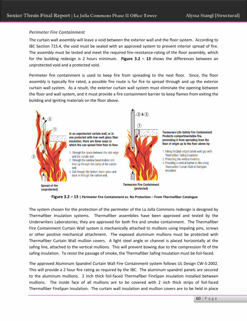
60 | P a g e
Alyssa Stangl [Structural]
Perimeter Fire Containment
The curtain wall assembly will leave a void between the exterior wall and the floor system. According to
IBC Section 715.4, the void must be sealed with an approved system to prevent interior spread of fire.
The assembly must be tested and meet the required fire-resistance-rating of the floor assembly, which
for the building redesign is 2 hours minimum. Figure 3.2 – 13 shows the differences between an
unprotected void and a protected void.
Perimeter fire containment is used to keep fire from spreading to the next floor. Since, the floor
assembly is typically fire rated, a possible fire route is for fire to spread through and up the exterior
curtain wall system. As a result, the exterior curtain wall system must eliminate the opening between
the floor and wall system, and it must provide a fire containment barrier to keep flames from exiting the
building and igniting materials on the floor above.
The system chosen for the protection of the perimeter of the La Jolla Commons redesign is designed by
Thermafiber Insulation systems. Thermafiber assemblies have been approved and tested by the
Underwriters Laboratories; they are approved for both fire and smoke containment. The Thermafiber
Fire Containment Curtain Wall system is mechanically attached to mullions using impaling pins, screws
or other positive mechanical attachment. The exposed aluminum mullions must be protected with
Thermafiber Curtain Wall mullion covers. A light steel angle or channel is placed horizontally at the
safing line, attached to the vertical mullions. This will prevent bowing due to the compression fit of the
safing insulation. To resist the passage of smoke, the Thermafiber Safing Insulation must be foil-faced.
The approved Aluminum Spandrel Curtain Wall Fire Containment system follows UL Design CW-S-2002.
This will provide a 2 hour fire rating as required by the IBC. The aluminum spandrel panels are secured
to the aluminum mullions. 2 inch thick foil-faced Thermafiber FireSpan Insulation installed between
mullions. The inside face of all mullions are to be covered with 2 inch thick strips of foil-faced
Thermafiber FireSpan Insulation. The curtain wall insulation and mullion covers are to be held in place
Figure 3.2 – 13 | Perimeter Fire Containment vs. No Protection – From Thermafiber Catalogue

61 | P a g e
Alyssa Stangl [Structural]
on impaling pins by clinch shields. Thermafiber Safing Insulation, 4 inches thick will be placed between
the concrete floor and the curtain wall insulation. It must be recessed 1 inch below the top surface of
the concrete floor. A stiff back steel channel will be installed behind the curtain wall insulation to
provide lateral support. Furthermore, FireCode Compound must be applied over the safing insulation at
a thickness of 1 inch. See Figure 3.2 – 14 for the Thermafiber assembly diagram.
Conclusion
The fire protection system for La Jolla Commons Phase II Office Tower has been detailed in this section.
The change of the building structure from concrete to steel required an adjustment to the fire-rated
assemblies of the floor systems, structural members, and exterior walls. As can be imagined, the change
to steel requires significantly more fire resistive material application than the original concrete system.
As will be showed in the construction cost analysis later in this report, the fire protection requirements
will contribute to the new structure cost and schedule duration.
Figure 3.2 – 14 | Thermafiber Perimeter Protection Assembly – from Thermafiber Catalogue

62 | P a g e
Alyssa Stangl [Structural]
Chapter 4 – Construction Breadth
4.1 – Cost Analysis
Concrete Estimate
The structural engineer of La Jolla Commons Phase II Office Tower indicated that the building was
designed in concrete because in California at the time of construction the concrete system was cheaper
than the steel system. As part of the analysis of changing structural systems, this claim was analyzed as
part of the second breadth.
The cost of the original building structure was provided by the property developer, Hines. The cost of
the building structure with general conditions and overhead was found to be $61.46 per square foot
including basement levels. This estimate included lower garage levels, foundations, shear walls, slabs,
concrete columns, and rebar. The cost of the concrete structural system, at about $24.5 million, was
about 30% of the total building cost.
Steel Estimate
A detailed cost analysis was
performed on the new building
structural system utilizing R.S.
Means Building Construction Cost
Data 2009 Edition. A location
modifier of 1.051 was utilized to
account for the increased cost in the
San Diego area. Also, a time
modifier of 1.13 was applied to
account for the increase in cost
between 2009 and April 2014,
assuming 3% inflation per year.
This steel system estimate includes all the steel and fireproofing that makes up the superstructure and
lateral moment frames. It also includes the existing concrete shear walls, foundation walls, mat
foundation, and lower level slabs and concrete columns. The concrete estimate included formwork,
reinforcing steel, concrete material and placement, and concrete finishing. Formwork, rebar, and
concrete were increased by 10%, 5% and 5% respectively to account for waste. All concrete take-offs
were performed based on the original building drawings. The steel take-offs were performed using RAM
Structural System output.
Table 4.1 – 1 shows a breakdown of the detailed cost analysis performed on the steel structure. As
expected, the structural steel framing makes up a majority of the building cost. The next highest
percentage, as expected, came from the special concrete shear walls located at the building core. For a
detailed breakdown of the cost analysis performed for the steel and concrete structures, see
spreadsheets located in Appendix L.
Table 4.1-1 | Steel Structure Cost Analysis

63 | P a g e
Alyssa Stangl [Structural]
Cost Comparison
After this study was performed, the claim that
the steel system would be more expensive than
the steel alternative was verified. As expected,
the steel system was more expensive, at $30
million, than the concrete system, at $24.5
million. This is about a 23% increase in the cost
of the building structure. It is important to note that some detail was not taken into account in the steel
estimate. Things such as connections from steel-to-steel and steel-to-concrete were not analyzed. Also,
the steel system would have an impact on the mat and the foundation wall designs. These things were
also not taken into account. Therefore, the difference in cost could be slightly different than that shown
in Table 4.1 – 2. The square foot cost of the original concrete system was $61.46 and the new steel
system is $65.05. Considering these results, it is apparent why the structure was designed in concrete
and not steel.
Table 4.1-2 | Cost Comparison Analysis

64 | P a g e
Alyssa Stangl [Structural]
4.2 – Schedule Analysis
Concrete Schedule
The schedule for the existing concrete system was obtained from the project manager and developer,
Hines, for La Jolla Commons Phase II Office Tower. The original building superstructure construction
began on September 12th, 2012 and ended on May 24th, 2013. This results in a total duration of 240
work days or 34 weeks for the building superstructure. The original schedule critical tasks included the
concrete slabs, concrete columns, and concrete shear
wall placement. Inspection of the special shear walls
also increased the project duration. Tasks such as
MEP rough in were found to not impact the
construction schedule because they were not
predecessors to any activities. The shear walls were
found to have the greatest impact on the building
schedule. In order in increase the pace of slab
forming and placement, the building was separated into three zones that were formed and placed with
three separate crews. Finishing of concrete occurred simultaneously on multiple levels. Two cranes
were used during construction. Table 4.2 – 1 shows the superstructure durations, and Figure 4.2 – 1
shows a portion of the original concrete schedule.
Figure 4.2 - 1 | Portion of Original Concrete Schedule – Provided by HINES
Table 4.2 - 1 | Original Schedule Duration
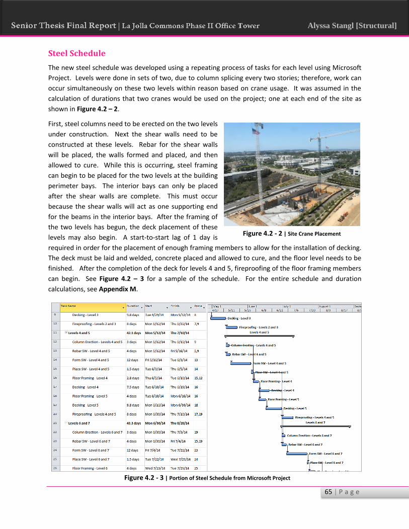
65 | P a g e
Alyssa Stangl [Structural]
Steel Schedule
The new steel schedule was developed using a repeating process of tasks for each level using Microsoft
Project. Levels were done in sets of two, due to column splicing every two stories; therefore, work can
occur simultaneously on these two levels within reason based on crane usage. It was assumed in the
calculation of durations that two cranes would be used on the project; one at each end of the site as
shown in Figure 4.2 – 2.
First, steel columns need to be erected on the two levels
under construction. Next the shear walls need to be
constructed at these levels. Rebar for the shear walls
will be placed, the walls formed and placed, and then
allowed to cure. While this is occurring, steel framing
can begin to be placed for the two levels at the building
perimeter bays. The interior bays can only be placed
after the shear walls are complete. This must occur
because the shear walls will act as one supporting end
for the beams in the interior bays. After the framing of
the two levels has begun, the deck placement of these
levels may also begin. A start-to-start lag of 1 day is
required in order for the placement of enough framing members to allow for the installation of decking.
The deck must be laid and welded, concrete placed and allowed to cure, and the floor level needs to be
finished. After the completion of the deck for levels 4 and 5, fireproofing of the floor framing members
can begin. See Figure 4.2 – 3 for a sample of the schedule. For the entire schedule and duration
calculations, see Appendix M.
Figure 4.2 - 2 | Site Crane Placement
Figure 4.2 - 3 | Portion of Steel Schedule from Microsoft Project

66 | P a g e
Alyssa Stangl [Structural]
This process will proceed up to the next two levels, requiring that the framing of the previous levels be
complete and the shear walls at those levels placed and cured. The process will then be similar to that
already described. This will repeat until the structure is topped out at the roof level. A typical two level
process takes about 43 days to complete.
The durations for this schedule were determined using daily output values from RS Means. The project
schedule was expedited using multiple crews on different tasks. For example, four crews were used or
the placement and finishing of the deck. It is assumed that two crews would be on one level and two on
the level above. Each crew would be responsible for one of two zones on the given level. For the
placement of the structural steel, two crews were assumed; this also stems from the assumption that
there will be two cranes on site. As a result, one crew will be responsible for each zone of the building
on a given level. Multiple crews were also assumed for the construction of the shear formwork and
reinforcing placement. Two crews were assumed for the placement of shear walls, requiring two
pumps. The new steel structure schedule was found to take 230 days or 32 weeks.
Schedule Comparison
The total length of the original concrete schedule was 240 days or 34 weeks; the new steel schedule was
found to be 230 days or 32 weeks. This is only a difference of 10 weekdays or two weeks. This was
surprising; originally, it was expected that the steel system would take significantly less time than the
cast-in-place concrete system. However, this was found to not be the case.
One factor that could have led to this outcome was the design decision to support the steel beams on
the concrete shear walls. The steel framing of floor levels could not be completed until the shear walls
at that particular level were complete; as a result, the time saving benefits of a steel system were offset
by the time it takes to form, place, and cure the concrete shear walls. Another item that increased the
duration of the steel system was the inclusion of fire protection materials. The original concrete system
did not require additional time for fireproofing like the new steel system. Additional time is also
required to inspect the new steel moment frames.
This result only further explains why La Jolla Commons was constructed of cast-in-place concrete and
not steel. If the steel schedule was greatly reduced, the higher cost of the steel system may have been
worth the time savings. However, because the schedule was not reduced by a significant amount, the
increased cost does not seem to be worth it.

67 | P a g e
Alyssa Stangl [Structural]
Overall System Comparison
La Jolla Commons Phase II Office Tower was originally designed to be a concrete structure. This
redesign changed the gravity system from concrete to steel and implemented the use of special moment
frames as part of the new lateral system. There are some positive and negative aspects to this redesign
that will be discussed, and a final recommendation will be made to the building owner.
First, the steel redesign resulted in a significantly lighter structure. This, in turn, considerably reduces
seismic forces, which was shown to be the controlling lateral load for the building’s lateral system. The
lower seismic forces will limit the required shear wall reinforcing and moment frame member sizes. As
was shown in the redesign of the concrete shear walls, the reduced forces allowed for a reduction in the
reinforcing required in the special concrete shear walls.
One concern that was present early in the steel system design process was the control of walking
induced vibrations in the office environment. As was shown in Chapter 2.1 of this report, the vibrations
of the steel system were controlled to the limits of AISC Design Guide 11. Vibrations in the steel system
will be left unnoticed to most occupants; therefore, this serviceability concern would not be a major
factor in deciding whether the building should be steel or concrete.
A downside to the steel system is that fire protective materials will be required on the structural
elements, unlike concrete which has inherent fire-resistive abilities. This will add additional cost and
time to the schedule. Another disadvantage is the decrease in floor-to-ceiling heights from 10’ – 8” to 9’
– 2” when switching to a steel structure. Although many office buildings have ceiling heights around 9’ –
0”, this may still be undesirable for the building owner.
Furthermore, there was a 23% increase in structure cost associated with the steel system. Also, there
was only a time savings of about two weeks for the steel construction schedule. As was mentioned in
Chapter 4.2, the time savings in the schedule is too minimal to offset the significant increase in cost with
the steel system.
Based on all of these factors, although a steel structure is certainly feasible, it was not necessarily the
best choice for this particular project. Concrete allows for higher floor-to-ceiling heights, lower costs
without a significant schedule increase, and does not require fire-resistive materials. Also, the concrete
system will inherently control vibrations. Thus, a concrete structure is probability the most efficient
choice for La Jolla Commons Phase II Office Tower.

68 | P a g e
Alyssa Stangl [Structural]
Conclusion
The report consisted of an analysis of La Jolla Commons Phase II Office Tower. After studying the
existing concrete system during the fall semester, it was decided to investigate the redesign of the
building structure in steel, using a design scenario as a guide. The gravity system was redesigned using
the original column locations and steel composite beams. A preliminary assessment was done to
determine a deck configuration and beam spacing to control walking induced vibrations. Next, RAM
Structural System was used to analyze and design the most economical cross sections for the beams and
columns. These designs were then verified using hand calculations. The final beam layout and design
was then analyzed according to AISC Design Guide 11 and found to be adequate for walking induced
vibrations.
The next portion of this report addressed the redesign of the building’s lateral system. The original
lateral system had an extreme torsional irregularity under seismic loading. Special steel moment frames
were added to the perimeter and designed for strength considerations. The designs were further
refined to allow for “clean columns” – columns that do not require web plates, flange stiffeners,
continuity plates, etc. Upon analyzing the building drift and torsion under seismic loading, drift was
found to be under the code maximum, and the torsional irregularity was found to no longer exist.
A breadth in architecture was done to assess the impact of changing the building structure on the
building height. It was found that, in order to meet the FAA height limitation of 198’-8”, the floor-to-
ceiling height would decrease from 10’-8’ for the concrete structure to 9’-2” for the steel structure.
Although many office buildings have ceiling heights around 9’-0”, this may be undesirable for the owner.
This breadth was further expanded to determine the fire-resistive requirements and designs for the new
steel structure. It was determined that Type 1B construction is required for the structural elements
except for columns which must be Type 1A. The columns required a 3 hour fire rating, which was
achieved using a layered gypsum encasement. The structural floor framing members required a 2 hour
fire rating, which was achieved using 1.5” of spray fire proofing materials. A perimeter fire containment
assembly was also selected.
The second breadth analyzed the schedule length and cost of the building structure. It was found that
the new steel system costs about 23% more than the existing concrete system. This analysis was based
on original cost information provided by Hines, and a cost analysis performed using RS Means 2009. A
schedule analysis was also performed. It was found that the steel system only takes about 2 weeks less
to construct than the concrete system.
Although there are benefits to the steel system, including reduced seismic loads and no torsional
irregularities, the steel system may not be the most effective design for this particular project. The
concrete system will allow for higher floor-to-ceiling heights, lower costs without a significant schedule
increase, and does not require additional fire-resistive materials. Therefore, the concrete structure is
probably the most efficient choice for La Jolla Commons Phase II Office Tower.

69 | P a g e
Alyssa Stangl [Structural]
References American Concrete Institute . (2011). Buiding Code Requirements for Structural Concrete (ACI 318-11).
American Institute of Steel Construction. (2011). Steel Construction Manual (Fourteenth ed.). United
States of America : AISC.
American Society of Civil Engineers. (2010). ASCE 7-10: Minimum Design Loads for Buildings and Other
Structures .
Bentley Systems, Inc. (2011, June). RAM Frame User Manual - The RAM Structural System V8i, 14.04.
Bentley Systems, Inc. (2011, June). RAM Frame Steel Post Processors - The RAM Structural System V8i,
14.04.
Bentley Technical Support Group. (2014). RAM Structural System - Walls FAQ. Retrieved from Structural
Analysis and Design - WIKI:
https://communities.bentley.com/products/structural/structural_analysis___design/w/structur
al_analysis_and_design__wiki/7578.ram-ss-walls-faq.aspx
California Building Standards Commission. (2013). California Building Code.
DeStefano, J. (2005, November). Fire Protection of Structural Steel... For Dummies. Structure Magazine,
17-20.
Hanagan, L. M., & Kim, T. (2005, FIRST QUARTER). Preliminary Assessment for Walking-Induced
Vibrations in Office Environments. Engineering Journal , 15-30.
International Code Council. (2012). International Building Code.
Murray, T. M., Allen, D. E., & Ungar, E. E. (1997). Design Guide 11: Floor Vibrations Due to Human
Activity . United state of America : AISC.
Nucor Vulcraft Group. (2008). Vulcraft Steel Roof & Floor Deck . Steel Deck Institute.
R.S. Means Company, Inc. (2009). RS Means Building Construction Cost Data (67th Annual Edition ed.).
(P. Phillip R. Waier, Ed.)
Shneur, V. (2009, June). In the Moment. Modern Steel Construction, 40-44.
Shriver, J. (2009). Perimeter Fire Containment - The Basics. Wabash, IN.
Thermafiber Inc. (n.d.). Thermafiber Life-Safey Fire Containment Systems, 07210/THC BuyLine 2999.
Underwriter Laboratories. (2014, February 08). Fire-resistance Design No. N708. Retrieved 2014, from
ULtimate Fire Wizard: http://database.ul.com/cgi-bin/ulweb/LISEXT/1FRAME/Fire
ResistanceWizard.html

70 | P a g e
Alyssa Stangl [Structural]
Underwriter Laboratories. (2014, February 22). Fire-resistance Design No. X508. Retrieved 2014, from
ULtimate Fire Wizard: http://database.ul.com/cgi-bin/ulweb/LISEXT/1FRAME/FireResistance
Wizard.html
NOTE: In addition to the sources listed above, course notes were utilized from many courses in the Penn
State Architectural Engineering Department.