semi-analytical vibration characteristics of rotating ... · f.ebrahimi and m.mokhtari /...
TRANSCRIPT

1319
Abstract
Free vibration analysis of rotating functionally graded (FG) thick
Timoshenko beams is presented. The material properties of FG
beam vary along the thickness direction of the constituents ac-
cording to power law model. Governing equations are derived
through Hamilton’s principle and they are solved applying differ-
ential transform method. The good agreement between the results
of this article and those available in literature validated the pre-
sented approach. The emphasis is placed on investigating the
effect of several beam parameters such as constituent volume
fractions, slenderness ratios, rotational speed and hub radius on
natural frequencies and mode shapes of the rotating thick FG
beam.
Keywords
Free Vibration, Functionally Graded material, Rotating Beam,
Differential Transform Method, power-law model.
Semi-analytical Vibration Characteristics
of Rotating Timoshenko Beams Made
of Functionally Graded Materials
1 INTRODUCTION
The laminated composite structures can be tailored to design advanced structures, but the sharp
change in the properties of each layer at the interface between two adjacent layers causes large in-
terlaminar shear stresses that may eventually give rise to well-known phenomenon known as delam-
ination. Such detrimental effects can be mitigated by grading the properties in a continuous manner
across the thickness direction resulting in a new class of materials known as ‘functionally graded
materials’ (FGMs) (Ebrahimi, 2013). In an effort to develop the super heat resistant materials, Jap-
anese material scientists proposed the concept of FGM in the early 1980s. These materials, which
are microscopically heterogeneous and are typically made from isotropic components, such as metals
and ceramics, were initially designed as thermal barrier materials for aerospace structures and fu-
sion reactors (Ebrahimi & Rastgoo, 2008a, b). FGMs are composite materials with inhomogeneous
Farzad Ebrahimi*
Mohadese Mokhtari
Department of Mechanical Engineering,
Faculty of Engineering, Imam Khomeini
International University, Qazvin, Iran,
P.O.B. 16818-34149
*Corresponding Author email:
http://dx.doi.org/10.1590/1679-78251446
Received 06.07.2014
In revised form 25.11.2014
Accepted 26.01.2015
Available online 07.02.2015
1320 F.Ebrahimi and M.Mokhtari / Semi-analytical Vibration Characteristics of Rotating Timoshenko Beams Made of Functionally Graded Materials
Latin American Journal of Solids and Structures 12 (2015) 1319-1339
micromechanical structure and are generally composed of two different parts such as ceramic and
metal in which the material properties changes smoothly between two surfaces. This kind of materi-
al as a novel generation of composites of microscopical heterogeneity are achieved by controlling the
volume fractions, microstructure, porosity, etc. of the material constituents during manufacturing,
resulting in spatial gradient of macroscopic material properties of mechanical strength and thermal
conductivity. As a result, In comparison with traditional composites, FGMs possess various ad-
vantages, for instance, ensuring smooth transition of stress distributions, minimization or elimina-
tion of stress concentration, and increased bonding strength along the interface of two dissimilar
materials. Therefore, FGMs have received wide applications in modern industries including aero-
space, mechanical, electronics, optics, chemical, biomedical, nuclear, and civil engineering to name a
few during the past two decades. Motivated by these engineering applications, FGMs have also
attracted intensive research interests, which were mainly focused on their static, dynamic and vi-
bration characteristics (Ebrahimi et al. 2009a, b).
Further, the increasing use of beams as structural components in various fields such as marine,
civil and aerospace engineering has necessitated the study of their vibration behavior and a large
number of studies can be found in literature about transverse vibration of uniform isotropic beams.
In this study, a relatively new approach called differential transformation method (DTM) is applied
in analyzing vibration analysis of rotating FG beams. The concept of DTM was first proposed by
Zhou (1986) in solving linear and non-linear initial value problems in electrical circuit analysis. The
superiority of the DTM is its simplicity and good precision and depends on Taylor series expansion
while it takes less time to solve polynomial series. It is different from the traditional high order
Taylor’s series method, which requires symbolic computation of the necessary derivatives of the
data functions. With this method, it is possible to obtain highly accurate results or exact solutions
for differential equations. With this technique, the given partial differential equation and related
initial conditions are transformed into a recurrence equation that finally leads to the solution of a
system of algebraic equations as coefficients of a power series solution. This method is useful for
obtaining exact and approximate solutions for linear and nonlinear ordinary and partial differential
equations and there is no need for linearization or perturbation. Also large computational work and
round-off errors are avoided. It’s a proper method to analyze beam vibrations. Study on rotating
Timoshenko beams by differential transform method has been presented by some researchers (Ho
and Chen, 2006; Mei, 2008).
In comparison with FGM shells and plates, there are fewer researches in literature about FGM
beams. Among those, Navier type solution method has been applied by Aydogdu and Taskin (2007)
to study free vibration of FG beams with simply supported edges. Kapuria et al. (2008) found vi-
bration response of layered FG beams. Li et al. (2013) suggested a unified approach for analyzing
free vibration of Euler and Timoshenko FG beams. Sina et al. (2009) analyzed the free vibration of
FG beams with an analytical method; they used a new beam theory which is a little different from
first-order shear deformation beam theory. Simsek (2010) has studied free vibration response of FG
beam for different higher order beam theories. Recently Pradhan and Chakraverty (2013) have
presented free vibration response of Euler and Timoshenko FG beams under various boundary con-
ditions. Ke et al. (2010) have studied nonlinear vibration of non-rotating FG beams using both ex-
ponential law and power law distribution of material properties. Recently, Li et al (2013) has inves-

F.Ebrahimi and M.Mokhtari / Semi-analytical Vibration Characteristics of Rotating Timoshenko Beams Made of Functionally Graded Materials 1321
Latin American Journal of Solids and Structures 12 (2015) 1319-1339
tigated the free vibration of non-rotating functionally graded beams with exponential variation of
material properties. It is to be mentioned that in two above aforesaid articles the FG beam is not
rotating.
Rotating beams play an important role in the modeling of engineering applications such as tur-
bine blades, airplane propellers and robot manipulators among others. This subject has been inves-
tigated with different level of intensity, at least, over the last four decades. However, to the best of
the author’s knowledge, the research work on rotating beams made of functionally graded materials
is scarce. Recently Mohanty et al. (2013) used finite element method to study free vibration of
sandwich and ordinary rotating FG beams. Shahba et al. (2013) have investigated the free vibration
of centrifugally stiffened tapered FG beams. However, in these formulations the material properties
of beam vary along the length of the beam while it is commonly not applicable in real structures.
Also the effects of shear deformation and rotary inertia were not taken into account. Although
Classical Euler–Bernoulli beam theory was used successfully for isotropic beams but since it neglects
shear deformation effects, it gives unreliable results for advanced materials, e.g. composites and
functionally graded materials (FGMs).
Motivated by these considerations, the need for investigation of vibration characteristics of the
functionally graded thick beams considering the effect of shear deformation and rotary inertia is
very much felt. In this study, the vibration characteristics of rotating FG beam is analyzed within
the context of Timoshenko beam theory. The material properties are assumed to be graded along
the thickness of the beam according to FG power-law distribution. The governing equations are
derived and solved by applying the semi-analytical differential transform method. Comparisons with
the results from the existing literature are provided for validation in special cases. Numerical results
are presented to examine the effect of several beam parameters such as constituent volume frac-
tions, slenderness ratios, rotational speed and hub radius on vibration behavior of the rotating thick
FG beam.
2 THEORY AND FORMULATION
2.1. Power-law Functionally Graded Material (P-FGM) Beam
One of the most favorable models for FGMs is the power-law model, in which material properties of
FGMs are assumed to vary according to a power law about spatial coordinates. The coordinate
system for FGM rotating beam is shown in Fig. 1. The length of the beam is L and thickness is h.
The FG beam is attached to periphery of a rigid hub of radius R and the hub rotates about z axis
at a constant angular speed Ω. A Cartesian coordinate system O(x, y, z) is defined on the central
axis of the beam where the x axis is taken along the central axis, the y-axis in the width direction
and the z-axis in the depth direction. The FG beam is assumed to be composed of ceramic and
metal and effective material properties (Pf) of the FG beam such as Young’s modulus Ef, shear
modulus Gf and mass density ρf are assumed to vary continuously in the thickness direction (z-axis
direction) according to an power function of the volume fractions of the constituents while the Pois-
son’s ratio is assumed to be constant in the thickness direction. According to the rule of mixture,
the effective material properties, P, can be expressed as (Şimşek, M., and T. Kocatürk, 2010):

1322 F.Ebrahimi and M.Mokhtari / Semi-analytical Vibration Characteristics of Rotating Timoshenko Beams Made of Functionally Graded Materials
Latin American Journal of Solids and Structures 12 (2015) 1319-1339
Pf = PcVc + PmVm (1)
Where Pm, Pc, Vm and Vc are the material properties and the volume fractions of the metal and the
ceramic constituents related by:
Vc +Vm = 1 (2a)
The volume fraction of the metal constituent of the beam is assumed to be given by:
Vc = (z
h+
1
2)q (2b)
Here q is the non-negative variable parameter (power-law exponent) which determines the material
distribution through the thickness of the beam. Therefore, from Eqs. (1)–(2), the effective material
properties of the FG beam can be expressed as follows:
Pf(z) = (Pc − Pm) (z
h+
1
2)q+ Pm (3)
According to this distribution, bottom surface (z = -h/2) of functionally graded beam is pure metal,
whereas the top surface (z = h/2) is pure ceramics.
2.2. Formulation of FGM Beam Using Timoshenko Beam Theory
In a Cartesian coordinate system, x is the distance of the point from the hub edge parallel to beam
length, u0 is the axial displacement due to the centrifugal force, z is the vertical distance of the
point from the middle plane, w is the transverse displacement of any point on the neutral axis and
θ is the rotation due to bending. Displacement field components are considered based on Timoshen-
ko beam theory. Considering Hodges et al. (1981) assumption and neglecting terms which are great-
er than ε2 strain-displacement and strain energy simplified relations are calculated as follows:
εxx = u0′ − zθ′ +
(w′)2
2 (4)
γxz = w′ − θ (5)
γxy = 0 (6)
In addition, bending strain energy Ub and shear strain energy Us are given respectively by:
Ub = ∭E(z)ε2
2 dV
V (7)
Us = ∭G(z)γ2
2 dV
V (8)

F.Ebrahimi and M.Mokhtari / Semi-analytical Vibration Characteristics of Rotating Timoshenko Beams Made of Functionally Graded Materials 1323
Latin American Journal of Solids and Structures 12 (2015) 1319-1339
Figure 1: Typical functionally graded beam with Cartesian coordinates.
Substituting equations (4-6) into equations (7-8) leads to
Ub = 1
2∫ ∫ E(z){u0
′ − zθ′ +(w′)2
2}2
L
0A dAdx (9)
Us = ∭G(z)(γxy
2+γxz2)
2 dV
V (10)
Further, the total strain energy is given by:
U = Us + Ub (11)
The axial displacement u0′ (x), which is uniform across the cross section is related to strain ε0(x) by:
u0′ (x) = ε0(x) =
T(x)
A1 (12)
In which T(x) is centrifugal force and is defined as:
T(x) = ∫ B1L
xΩ2(R + x)dx (13)
According to equations (9-13) bending and shear strain energy are obtained respectively as follows:
Ub =1
2∫ (A2
L
0
(θ′)2 + T(w′)2)dx + const
(14)
Us = 1
2 ∫ C(w′ − θ)2L
0dx (15)
Here, A1 and A2 are bending rigidity and axial rigidity of the beam cross section respectively and
are defined as:
( 𝐴1 , 𝐴2) = ∫ 𝐸(𝑧)(1, 𝑧2)ℎ/2
−ℎ/2𝑑𝐴 (16)
And B1and C are normal inertia term and shear rigidity factor respectively, which are defined as
follows:
B1 = ∫ ρ(z)(1, z2)h/2
−h/2dA (17)

1324 F.Ebrahimi and M.Mokhtari / Semi-analytical Vibration Characteristics of Rotating Timoshenko Beams Made of Functionally Graded Materials
Latin American Journal of Solids and Structures 12 (2015) 1319-1339
C = ∫kG(z)dA
(18)
Where A, ρ and E are the area of cross-section, the mass density and modulus of elasticity of the
beam respectively and G is the shear modulus and k is the Timoshenko shear correction factor
which has been assumed equal to the isotropic case, i.e. k=5/6. Further, substituting equations
(14-15) into equation (11) one gets the total strain energy of the beam in the following form:
U =1
2∫ A2
L
0
(θ′)2 + T(w′)2 + C(w′ − θ) 2dx (19)
Also the kinetic energy expression is given as:
τ = 1
2∫ ∫ (Vx
2 + Vy2 + Vz
2)ρ dA dxL
0A (20)
And the total velocity V can be expressed in terms of deformed positions as:
V = (x1 −Ωy1)i +(y1 +Ωyx1)j + z1k (21)
Vx = −ξθ − ηΩ (22)
Vy = (R + x + u0 − ξθ)Ω (23)
Vz = ω (24)
Now substituting equations (22-24) into equation (20) kinetic energy is obtained as follows:
τ =1
2 ∫ [B1
L
0ω 2 + A2θ
2 + A2Ω2θ2]dx (25)
2.3. Deriving Governing Equations for Rotating FG Beam
Hamilton’s principle is used herein to derive the equations of motion. The principle can be stated in
analytical form as:
∫ (δU + δV − δτ) = 0t2t1
(26)
Here, t1 and t2 are the initial and end time, respectively; δU is the virtual variation of the strain
energy; δV is the virtual variation of the potential energy; and δτ is the virtual variation of the
kinetic energy. According to Hamilton’s principle, the equations of motion can be obtained as:
−B2 θ + B2Ω2 θ + A2θ
′′ + kC(W′ − θ) = 0 (27)
−B1W + (TW′)′ + kC(W′′ − θ′) = 0 (28)
Further, the two ends of the Timoshenko cantilever beam (x = 0 and x = L) are subjected to the
following boundary conditions:
at x=0: W(0) = 0 , ϴ (0) = 0 (29)
at x=L: ϴ'(1) = 0 , W'(1)- ϴ (1) = 0 (30)

F.Ebrahimi and M.Mokhtari / Semi-analytical Vibration Characteristics of Rotating Timoshenko Beams Made of Functionally Graded Materials 1325
Latin American Journal of Solids and Structures 12 (2015) 1319-1339
Assuming simple harmonic oscillation, w and θ can be written as:
W(x, t) = W(x)eiωt (31)
θ(x, t) = θ(x)eiωt (32)
Substituting equations (31) and (32) into equations (27) and (28), the governing equations are as
follows:
B2 ω2 θ + B2Ω
2 θ + A2θ′′ + kC(W′ − θ ) = 0 (33)
B1ω2W + (TW′)′ + kC(W′′ − θ′) = 0 (34)
The dimensionless parameters which founded according to FGM characteristics are used to simplify
the equations and to make comparisons with the studies in literature such as Banerjee (2001) can
be given as follows:
η2 =B1L
4Ω2
A2, r2 =
B2
A1L2 , δ =
R
L , ξ =
x
L
μ2 = B1L
4ω2
A2, s2 =
A2
kCL2 , W(ξ) =W
L (35)
Then dimensionless expressions for centrifugal force and governing equations are obtained as fol-
lows:
T(ξ) = B1Ω2L2 [δ(1 − ξ) +
(1 − ξ2)
2]
(36)
θ′′ + η2r2 (1 +ω2
Ω2) θ +
1
s2(W′ − θ) = 0
(37a)
{[δ(1 − ξ) +(1 − ξ2)
2] W′}
′
+ (ω2
Ω2)W +
1
s2η2(W′′ − θ′) = 0
(37b)
Additionally, the dimensionless boundary conditions can be expressed as follows
ξ = 0 W = �� = 0 (38a)
𝜉 = 1 𝑑W
𝑑𝜉− �� =
𝑑��
𝑑𝜉= 0
(38b)
2.4. Implementation of Differential Transform Method
Generally, it is rather difficult to derive an analytical solution for Eqs. (37-38) due to the nature of
non-homogeneity. In this circumstance, the DTM is employed to translate Eqs. (33-34) into a set of
ordinary equations. First, the procedure of differential transform method is briefly reviewed. Differ-
ential transformation of function y(x) according to Abdel-Halim Hassan (2002) is defined as follows:

1326 F.Ebrahimi and M.Mokhtari / Semi-analytical Vibration Characteristics of Rotating Timoshenko Beams Made of Functionally Graded Materials
Latin American Journal of Solids and Structures 12 (2015) 1319-1339
Y(k) = 1
k![
dk
dxk y(x)]x=0
(39)
In which y(x) is the original function and Y(k) is the transformed function. Besides the differential
inverse transformation of Y(k) can be obtained as follows:
y(x) = ∑ xkY(k)∞n+1 (40)
Consequently from equations (39-40) we obtain:
y(x) = ∑xk
k![
dk
dxk y(x)]x=0
∞k=0 (41)
Equation (41) reveals that the concept of the differential transformation is derived from Taylor’s
series expansion. In real applications the function y(x) in equation (40) can be written in a finite
form as: y(x) = ∑ xkY(k)n
k=0 (42)
In this calculations y(x) = ∑ xkY(k)∞n+1 is small enough to be neglected, and n is determined by the
convergence of the eigenvalues. In Table (1) the basic theorem of DTM is stated while table (2)
presents the differential transformation of conventional boundary conditions. Applying the DTM
rule on the equations of motion (37) and boundary conditions (38) the next four equations are ob-
tained as:
Original function Transformed function
y(x) = λφ(x) Y(k) = λΦ(k)
y(x) = φ(x) ± θ(x) Y(k) = Φ(k) ± Θ(k)
y(x) =dφ
dx Y(k) = (k + 1)Φ(k + 1)
y(x) =d2φ
dx2 Y(k) = (k + 1)(k + 2)Φ(k + 1)
y(x) = φ(x)θ(x) Y(k) = ∑Φ(l)Θ(k − l)
k
l=0
y(x) = xm Y(k) = δ(k − m) = { 1 k = m 0 k ≠ m
Table 1: Some of the transformation rules of the one-dimensional DTM.

F.Ebrahimi and M.Mokhtari / Semi-analytical Vibration Characteristics of Rotating Timoshenko Beams Made of Functionally Graded Materials 1327
Latin American Journal of Solids and Structures 12 (2015) 1319-1339
X=1 X=0
Transformed BC Original BC Transformed BC Original BC
∑F[k] = 0
∞
k=0
f(1)=0
F[0]=0
f(0)=0
∑kF[k] = 0
∞
k=0
df
dx(1) = 0
F[1]=0
df
dx(0) = 0
∑k(k − 1)F[k] = 0
∞
k=0
d2f
dx2(1) = 0
F[2]=0
d2f
dx2(0) = 0
∑k(k − 1)(k
∞
k=0
− 2)F[k] = 0
d3f
dx3(1) = 0
F[3]=0
d3f
dx3(0) = 0
Table 2: Transformed boundary conditions (B.C.) based on DTM.
(δ + 0.5 +1
s2η2) (k + 1)(k + 2)W(k + 2) − δ(k + 1)2W(k + 1) + (
ω2
Ω2−
k(k + 1)
2)W(k)
−1
s2η2(k + 1)θ(k + 1) = 0
(43)
(k + 1)(k + 2)θ(k + 2) + [η2r2 (1 +ω2
Ω2) −
1
s2] θ(k) +
1
s2(k + 1)W(k + 1) = 0
(44)
∑k ∗ Θ(k) = 0
n
i=0
(45)
∑k ∗ w(k) − Θ(k) = 0
n
i=0
(46)
Here, W(k) and θ (k) are the differential transforms of w(ξ) and θ (ξ), respectively. Substituting
W(k) and θ (k) in eqs. (45-46) we have:
Mj1(n)
c1 + Mj2(n)
c2 = 0 , j = 1,2,3,… , n (47)
In which Mij are polynomials in terms of ω corresponding to nth term. The matrix form of equation
(47) can be prescribed as:

1328 F.Ebrahimi and M.Mokhtari / Semi-analytical Vibration Characteristics of Rotating Timoshenko Beams Made of Functionally Graded Materials
Latin American Journal of Solids and Structures 12 (2015) 1319-1339
[M11
(n)M12
(n)
M21(n)
M22(n)
] {c1c2
} = 0
(48)
Further, studying the existence condition of the non-trivial solutions yields the following character-
istic equation:
|M11
(n)M12
(n)
M21(n)
M22(n)
| = 0
(49)
Solving equation (49), the ith estimated eigenvalue for nth iteration (ω = ωi(n)
) may be obtained
and the total number of iterations is related to the accuracy of calculations which can be deter-
mined by the following equation:
|ωi(n)
− ωi(n−1)
| < ε (50)
In this study ε=0.0001 considered in procedure of finding eigenvalues which results in 4 digit preci-
sion in estimated eigenvalues. Further a Matlab program has been developed according to DTM
rule stated above, in order to find eigenvalues and plot mode shapes.
3 RESULTS AND DISCUSSION
In the present section a numerical testing of the procedure as well as parametric studies are per-
formed in order to establish the validity and usefulness of the DTM approach and the influence of
different beam parameters such as constituent volume fractions, slenderness ratios, rotational speed
and hub radius on the natural frequencies and mode shapes of the rotating beam is examined. The
material properties of the power-law FG constituents are presented in Tables 3 and 4. Relations
described in equation (51) are performed in order to calculate the non-dimensional natural frequen-
cies.
λ = ωL2
h√
ρm
Em
(51)
Figures 2-4 show the convergence study of DTM method for first three frequencies. It is found that
in DTM method after a certain number of iterations eigenvalues converged to a value with good
precision, so the number of iterations is important in DTM method convergence. This fact is obvi-
ous in Figures 2 and 3. As seen in Figure 4, third natural frequency converged after 37 iterations
with 4 digit precision while according to figure 2 the first natural frequency converged after 33 iter-
ations.
Alumina( Al2O3) aluminum unit properties
380 70 GPa E
3960 2702 Kg/m3 ρ
0.3 0.3 - ν
Table 3: material properties of the FGM constituents (Simsek, 2010).

F.Ebrahimi and M.Mokhtari / Semi-analytical Vibration Characteristics of Rotating Timoshenko Beams Made of Functionally Graded Materials 1329
Latin American Journal of Solids and Structures 12 (2015) 1319-1339
60694,20
60694,40
60694,60
60694,80
60695,00
25 27 29 31 33 35 37 39
λ
n
alumina (Al2O3) aluminum unit properties
380 70 GPa E
3800 2700 Kg/m3 ρ
0.23 0.23 - ν
Table 4: material properties of the FGM constituents (Sina et al., 2009).
Figure 2: Convergence study for the first frequency of rotating FG beam, q=0, 𝜂=8.
Figure 3: Convergence study for the second frequency of rotating FG beam, q=0, 𝜂=8.
Figure 4: Convergence study for the third frequency of rotating FG beam, q=0, 𝜂=8.
10154,20
10154,60
10155,00
10155,40
25 27 29 31 33 35 37 39
λ
n
29892,80
29893,00
29893,20
29893,40
25 27 29 31 33 35 37 39
λ
n

1330 F.Ebrahimi and M.Mokhtari / Semi-analytical Vibration Characteristics of Rotating Timoshenko Beams Made of Functionally Graded Materials
Latin American Journal of Solids and Structures 12 (2015) 1319-1339
Table 5: Comparison of fundamental frequencies of FG rotating beams for different L/h ratios.
% Difference Simsek (2010) Present q
0.00359 1.9496 1.9495 ceramic
0.7711 1.8145 1.8286 0.2
3.5413 1.66046 1.7214 0.5
6.6802 1.26495 1.3555 10
0.6697 1.01297 1.0198 metal
Table 6: Comparison of fundamental frequencies of FG rotating
beams for different constituent volume fraction exponent.
After looking into the satisfactory results for the convergence of frequencies, one may compare the
nondimensional frequencies of FG beam associated with different slenderness ratios and constituent
volume fraction exponents. To demonstrate the correctness of present study the results for FG ro-
tating beam are compared with the results of FG rotating beams presented by Simsek (2010) and
Sina et al. (2009). Table 5 compares the results of the present study and the results presented by
Simsek (2010) which has been obtained by using Lagrange’s equations for FG rotating beam with
different slenderness ratios while Table 6 compares the presented results with ones by Sina et al.
(2009) which has been obtained using an analytical method for various constituent volume fraction
exponents. One may clearly notice here that the fundamental frequency parameters obtained in the
present investigation are in approximately close enough to the results provided in these literatures
that are used for comparison and validates the proposed method of solution.
Frequency parameters of power-law FG beam affected by various parameters are studied in Ta-
bles 7-9. Inspection of these tables also reveals that an increase in the value of the power-law expo-
nent leads to a decrease in the fundamental frequencies. The highest frequency values are obtained
for full ceramic beam (q = 0) while the lowest frequency values are obtained for full metal beam (q
→∞). This is due to the fact that, an increase in the value of the power-law exponent results in a
decrease in the value of elasticity modulus and the value of bending rigidity. In other words, the
beam becomes flexible as the power law exponent increases. Therefore, as also known from mechan-
ical vibrations, natural frequencies decrease as the stiffness of a structure decreases. It is also inter-
esting to note that the decrease in the frequency values due to the increase in the power-law expo-
nent is almost the same for higher mode frequencies.
L/h =100 L/h =30 L/h =10
1.0030 1.0030 0.9960 Sina et al.(2009)
0.9930 0.9922 0.9858 Present
1.0070 1.0884 1.0346 % Difference

F.Ebrahimi and M.Mokhtari / Semi-analytical Vibration Characteristics of Rotating Timoshenko Beams Made of Functionally Graded Materials 1331
Latin American Journal of Solids and Structures 12 (2015) 1319-1339
Figure 5: The effect of power-law exponent (q<10) on first natural
frequency with different rotational speed parameters, L/h=10.
Figure 6: The effect of power-law exponent (q>10) on first natural
frequency with different rotational speed parameters, L/h=10.
Also, note that the power-law exponent plays an important role on the fundamental frequency of
the FG beam. The effect of power-law exponent on first natural frequency of the FG rotating beam
with different rotational speed parameters has been illustrated in Figures 5 and 6 for two cases of
q<10 and q>10 respectively.
0,5
1,5
2,5
3,5
4,5
5,5
0 2 4 6 8 10
λ
q
η=0 η=2 η=4
η=6 η=8
0,5
1,5
2,5
3,5
4,5
10 100 1000
λ
q
η=0 η=2 η=4
η=6 η=8
7
9
11
13
15
17
0 2 4 6 8 10
λ2
q
η=8 η=6 η=4
η=2 η=0
1332 F.Ebrahimi and M.Mokhtari / Semi-analytical Vibration Characteristics of Rotating Timoshenko Beams Made of Functionally Graded Materials
Latin American Journal of Solids and Structures 12 (2015) 1319-1339
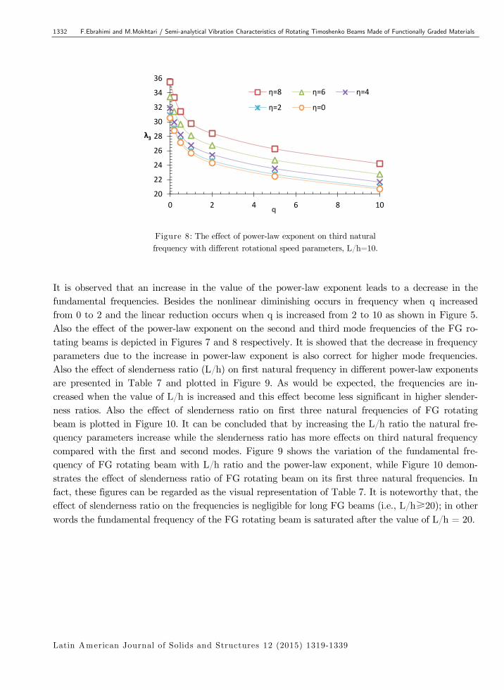
Figure 8: The effect of power-law exponent on third natural
frequency with different rotational speed parameters, L/h=10.
It is observed that an increase in the value of the power-law exponent leads to a decrease in the
fundamental frequencies. Besides the nonlinear diminishing occurs in frequency when q increased
from 0 to 2 and the linear reduction occurs when q is increased from 2 to 10 as shown in Figure 5.
Also the effect of the power-law exponent on the second and third mode frequencies of the FG ro-
tating beams is depicted in Figures 7 and 8 respectively. It is showed that the decrease in frequency
parameters due to the increase in power-law exponent is also correct for higher mode frequencies.
Also the effect of slenderness ratio (L/h) on first natural frequency in different power-law exponents
are presented in Table 7 and plotted in Figure 9. As would be expected, the frequencies are in-
creased when the value of L/h is increased and this effect become less significant in higher slender-
ness ratios. Also the effect of slenderness ratio on first three natural frequencies of FG rotating
beam is plotted in Figure 10. It can be concluded that by increasing the L/h ratio the natural fre-
quency parameters increase while the slenderness ratio has more effects on third natural frequency
compared with the first and second modes. Figure 9 shows the variation of the fundamental fre-
quency of FG rotating beam with L/h ratio and the power-law exponent, while Figure 10 demon-
strates the effect of slenderness ratio of FG rotating beam on its first three natural frequencies. In
fact, these figures can be regarded as the visual representation of Table 7. It is noteworthy that, the
effect of slenderness ratio on the frequencies is negligible for long FG beams (i.e., L/h≥20); in other
words the fundamental frequency of the FG rotating beam is saturated after the value of L/h = 20.
20
22
24
26
28
30
32
34
36
0 2 4 6 8 10
λ3
q
η=8 η=6 η=4
η=2 η=0

F.Ebrahimi and M.Mokhtari / Semi-analytical Vibration Characteristics of Rotating Timoshenko Beams Made of Functionally Graded Materials 1333
Latin American Journal of Solids and Structures 12 (2015) 1319-1339
Table 7: Variation of the first three natural frequencies of FG rotating beam
with L/h ratio for various values of the power-law exponent, 𝜂 =8.
L/h=100 L/h =50 L/h =30 L/h=20 L/h=10 L/h = 5 mode q
5.1424 5.1410 5.1377 5.1312 5.098 4.9877 λ1 0
16.6578 16.6369 16.5877 16.4938 16.0314 14.6826 λ2
39.0092 38.8779 38.5744 38.0107 35.4915 29.8114 λ3
4.8235 4.8222 4.8191 4.8132 4.7829 4.6815 λ1 0.2
15.6247 15.6056 15.5607 15.475 15.0516 13.8066 λ2
36.5907 36.4711 36.1944 35.6797 33.3684 28.0963 λ3
4.5408 4.5396 4.5367 4.5312 4.5028 4.4077 λ1 0.5
14.709 14.6911 14.6491 14.5688 14.1718 13.0029 λ2
34.4464 34.3344 34.0752 33.593 31.4259 26.4718 λ3
4.3151 4.3139 4.3111 4.3057 4.2779 4.1853 λ1 1
13.978 13.9603 13.9191 13.8403 13.4523 12.4432 λ2
32.7335 32.6233 32.3686 31.8956 29.7817 25.0154 λ3
4.1395 4.1382 4.1353 4.1296 4.1008 4.0066 λ1 2
13.4086 13.3902 13.3473 13.2655 12.8662 11.7309 λ2
31.3980 31.2827 31.0167 30.525 28.3609 23.6558 λ3
3.8751 3.8738 3.8707 3.8648 3.8348 3.7400 λ1 5
12.5517 12.5325 12.4877 12.4027 11.9929 10.8707 λ2
29.3884 29.2671 28.9882 28.476 26.2714 21.7191 λ3
3.5772 3.5760 3.5731 3.5676 3.5396 3/4514 λ1 10
11.5868 11.5689 11.5270 11.4476 11.0652 10.0238 λ2
27.129 27.0154 26.7543 26.2751 24.2188 20.003 λ3
2.9644 2.9635 2.9614 2.9573 2.9364 2.8686 λ1 50
9.6022 9.5889 9.5579 9.4988 9.2106 8.3948 λ2
22.4846 22.4011 22.2084 21.8525 20.2897 16.9114 λ3
2.8304 2.8296 2.8277 2.8239 2.8047 2.7417 λ1 100
9.1684 9.1562 9.1277 9.0734 8.8073 8.0442 λ2
21.4696 21.3931 21.2166 20.8899 19.4438 16.2600 λ3
2.6899 2.6892 2.6874 2.6840 2.6666 2.6086 λ1 metal
8.7135 8.7024 8.6766 8.6272 8.3841 7.6763 λ2
20.4051 20.3359 20.1762 19.8796 18.5555 15.5780 λ3

1334 F.Ebrahimi and M.Mokhtari / Semi-analytical Vibration Characteristics of Rotating Timoshenko Beams Made of Functionally Graded Materials
Latin American Journal of Solids and Structures 12 (2015) 1319-1339
The other important parameter in vibration behavior of rotating FG beam is its rotational speed
parameter. Table 8 presents the variation of first three natural frequencies of FG rotating beam for
different rotational speed parameters (η =0, 2, 4, 6, 8) with different power-law exponents.
According to Table 8, increasing the rotational speed increases the first three natural frequencies
and as seen in Figure 11 ascending pattern is more sensitive for the first natural frequency. For
instance for FG beam with power-law exponent defined as q=2, increasing normal rotational speed
from 2 to 4 (100% increase), leads to 35%, 7.8%, 3.2% increase in first three natural frequencies
respectively.
Figure 9: Variation of the fundamental frequency of FG rotating
beam with L/h ratio for various power-law exponent.
Figure 10: Variation of the first three natural frequencies of FG rotating beam with L/h ratio, q=2 ،η=2
Figure 11: The effect of rotational speed on first three natural frequencies, L/h=10, q=0.5.
0
10
20
30
40
6 8 10 12 14 16 18 20
λ
L/h
λ1 λ2 λ3
0
5
10
15
20
25
30
35
0 1 2 3 4 5 6 7 8
λ
η
λ1 λ2 λ3

F.Ebrahimi and M.Mokhtari / Semi-analytical Vibration Characteristics of Rotating Timoshenko Beams Made of Functionally Graded Materials 1335
Latin American Journal of Solids and Structures 12 (2015) 1319-1339
The next set of results was obtained to demonstrate the effect of hub radius parameter on the non-
dimensional natural frequencies of the rotating FG beam. Variation of the first three natural fre-
quencies of rotating FG beam with various hub radius parameters is tabulated in Table 9. Figure 12
illustrates this effect for first three natural frequencies when L/h =10 ،η=2 and q=0. It is observed
that the non-dimensional natural frequencies increase with the hub radius parameter as expected
because of the increase in centrifugal stiffening of the beam.
Table 8: The effect of rotational speed parameter on natural frequencies
of FG rotating beam with different power law exponent for the case: L/h=10.
η=8 η=6 η=4 η=2 η=0 mode q
5.0980 4.0570 3.0801 2.2815 1.9381 λ1 0
16.0314 14.2743 12.8669 11.9408 11.6155 λ2
35.4915 33.4349 31.8701 30.8865 30.5505 λ3
4.7829 3.8061 2.8896 2.1405 1.8183 λ1 0.2
15.0516 13.4039 12.0844 11.2163 10.9114 λ2
33.3684 31.4429 29.9784 29.0582 28.7438 λ3
4.5028 3.5832 2.7204 2.0151 1.7118 λ1 0.5
14.1718 12.6208 11.3787 10.5617 10.2747 λ2
31.4259 29.6140 28.236 27.3701 27.0743 λ3
4.2779 3.4043 2.5846 1.9145 1.6263 λ1 1
13.4523 11.9779 10.7969 10.0198 9.7468 λ2
29.7817 28.0559 26.7429 25.9176 25.6356 λ3
4.1008 3.2636 2.4779 1.8353 1.5589 λ1 2
12.8662 11.4502 10.3153 9.5680 9.3053 λ2
28.3609 26.6944 25.4249 24.6263 24.3533 λ3
3.8348 3.1245 2.3176 1.7165 1.4577 λ1 5
11.9929 10.6646 9.5987 8.8962 8.6492 λ2
26.2714 24.6945 23.4913 22.7334 22.474 λ3
3.5396 2.8173 2.1392 1.5843 1.3454 λ1 10
11.0652 9.8384 8.8539 8.2049 7.9766 λ2
24.2188 22.7605 21.6475 20.9461 20.7062 λ3
2.9364 2.3370 1.7744 1.3142 1.1162 λ1 50
9.2106 8.1960 7.3828 6.8472 6.6589 λ2
20.2897 19.0941 18.1832 17.6101 17.4142 λ3
2.8047 2.2321 1.6947 1.2552 1.0662 λ1 100
8.8073 7.8393 7.0636 6.5530 6.3735 λ2
19.4438 18.3065 17.4405 17.5121 16.7097 λ3
2.6666 2.1220 1.6111 1.1934 1.0137 λ1 Metal
8.3841 7.4649 6.7286 6.2442 6.0738 λ2
18.5555 17.4791 16.6601 16.1453 15.9694 λ3

1336 F.Ebrahimi and M.Mokhtari / Semi-analytical Vibration Characteristics of Rotating Timoshenko Beams Made of Functionally Graded Materials
Latin American Journal of Solids and Structures 12 (2015) 1319-1339
Another set of results was obtained to illustrate some representative mode shapes of the rotating
FG beam. Figure 13 shows the first normalized mode shape of the rotating FG beam plotted for
different values of L/d (5, 20). The second and the third normalized mode shapes are plotted in
Figures 14 and 15. Seeing as the material properties are constant through the beam axis, no change
occurs in mode shapes and their profiles as presented in Figures 13-15.
mode δ=0 δ=0.02 δ=0.04 δ=0.06 δ=0.08 δ=0.1 δ=0.12
λ1 2.2815 2.2899 2.2983 2.3066 2.3149 2.3231 2.3314
λ2 11.9408 11.9495 11.9581 11.9667 11.9753 11.9839 11.9925
λ3 30.8865 30.896 30.9054 30.9149 30.9243 30.9338 30.9432
Table 9: The effect of hub radius parameter on the first three natural frequencies, L/h =10 ،η=2 ، q=0.
Figure 12: Effect of hub radius parameter on first three natural frequencies, L/h =10 ،η=2 ، q=0.
Figure 13: The normalized first mode shape of rotating FG beam for different slenderness ratios.
0
5
10
15
20
25
30
35
0 0,02 0,04 0,06 0,08 0,1 0,12
λ
δ
λ1
λ2
λ3
0
0,05
0,1
0,15
0,2
0,25
0,3
0,35
0,4
0 0,2 0,4 0,6 0,8 1
L/h=5,teta L/h=5,W
L/h=20,W L/h=20,teta

F.Ebrahimi and M.Mokhtari / Semi-analytical Vibration Characteristics of Rotating Timoshenko Beams Made of Functionally Graded Materials 1337
Latin American Journal of Solids and Structures 12 (2015) 1319-1339
Figure 14: The normalized second mode shape of rotating FG beam for different slenderness ratios.
Figure 15: The normalized third mode shape of rotating FG beam for different slenderness ratios.
4 CONCLUSIONS
In this paper a new model to study the vibration characteristics of rotating beams made of func-
tionally graded materials has been introduced using semi analytical differential transform method.
The model has been deduced employing a formulation accounting for shear-deformability relation-
ships. Results of the presented work are compared and validated with available results in literature.
Effect of different parameters includes constituent volume fractions, slenderness ratios, rotational
speed and hub radius on the natural frequencies and mode shapes of the rotating beam is investi-
gated. The DTM method is an accurate and uncomplicated numerical method to solve eigenvalue
problems. The presented expressions are convenient and efficient for the analysis of the FG beams
and they are valid for a wide range of vibration amplitudes. The FG beam is analyzed for Power-
law model, changing power-law exponent leads to different distributions of metal and ceramic in FG
beam. It is concluded that by increasing power-law exponent decreases the frequency parameters
while increasing the slenderness ratios resulted in increasing the frequency parameters; this effect
becomes less significant when the value become larger. Rotational speed has a considerable effect on
-0,3
-0,25
-0,2
-0,15
-0,1
-0,05
0
0,05
0,1
0,15
0 0,2 0,4 0,6 0,8 1
L/h=20,teta L/h=20,W
L/h=5,teta L/h=5,W
-0,15
-0,1
-0,05
0
0,05
0,1
0,15
0,2
0,25
0 0,2 0,4 0,6 0,8 1
L/h=5,teta L/h=5,W
L/h=20,teta L/h=20,W

1338 F.Ebrahimi and M.Mokhtari / Semi-analytical Vibration Characteristics of Rotating Timoshenko Beams Made of Functionally Graded Materials
Latin American Journal of Solids and Structures 12 (2015) 1319-1339
natural frequency parameter, variation of this parameter have a direct relation with frequency pa-
rameter. In comparison with other parameters hub radius has not a sensitive effect on natural fre-
quency, increasing hub radius increases natural frequency with low gradient.
References
Abdel-Halim Hassan, I. H. "On solving some eigenvalue problems by using a differential transformation." Applied
Mathematics and Computation 127.1 (2002): 1-22.
Aydogdu, Metin, and Vedat Taskin. "Free vibration analysis of functionally graded beams with simply supported
edges." Materials & design 28.5 (2007): 1651-1656.
Banerjee, J. R. "Dynamic stiffness formulation and free vibration analysis of centrifugally stiffened Timoshenko
beams." Journal of Sound and Vibration 247.1 (2001): 97-115.
Ebrahimi, F. "Analytical investigation on vibrations and dynamic response of functionally graded plate integrated
with piezoelectric layers in thermal environment." Mechanics of Advanced Materials and Structures 20.10 (2013):
854-870.
Ebrahimi, F., and A. Rastgoo. "Free vibration analysis of smart annular FGM plates integrated with piezoelectric
layers." Smart Materials and Structures 17.1 (2008a): 015044.
Ebrahimi, F, and A. Rastgoo. "An analytical study on the free vibration of smart circular thin FGM plate based on
classical plate theory." Thin-Walled Structures 46.12 (2008b): 1402-1408.
Ebrahimi, F., A. Rastgoo, and A. A. Atai. "A theoretical analysis of smart moderately thick shear deformable annu-
lar functionally graded plate." European Journal of Mechanics-A/Solids 28.5 (2009a): 962-973.
Ebrahimi, F., Naei, M.H. and Abbas Rastgoo. "Geometrically nonlinear vibration analysis of piezoelectrically actuat-
ed FGM plate with an initial large deformation." Journal of mechanical science and technology 23.8 (2009b): 2107-
2124.
Ho, Shing Huei, and Cha’O. Kuang Chen. "Free transverse vibration of an axially loaded non-uniform spinning
twisted Timoshenko beam using differential transform." International journal of mechanical sciences 48.11 (2006):
1323-1331.
Hodges, Dewey Yang, and Michael Yang Rutkowski. "Free-vibration analysis of rotating beams by a variable-order
finite-element method." AIAA Journal 19.11 (1981): 1459-1466.
Kapuria S, Bhattacharyya M, Kumar AN. Bending and free Vibration response of layered functionally graded
beams, a theoretical model and its experimental validation. “Composite Structures”, 82(3), (2008): 390-402.
Ke, Liao-Liang, Jie Yang, and Sritawat Kitipornchai. "An analytical study on the nonlinear vibration of functionally
graded beams." Meccanica 45.6 (2010): 743-752.
Li, X-F., Y-A. Kang and J-X. Wu. "Exact frequency equations of free vibration of exponentially functionally graded
beams." Applied Acoustics 74.3 (2013): 413-420.
Mei, C. "Application of differential transformation technique to free vibration analysis of a centrifugally stiffened
beam." Computers & Structures 86.11 (2008): 1280-1284.
Mohanty, S. C., R. R. Dash, and T. Rout. "Free Vibration of a Functionally Graded Rotating Timoshenko Beam
Using FEM." Advances in Structural Engineering 16.2 (2013): 405-418.
Pradhan, K. K., and S. Chakraverty. "Free vibration of Euler and Timoshenko functionally graded beams by Ray-
leigh–Ritz method." Composites Part B: Engineering 51 (2013): 175-184.
F.Ebrahimi and M.Mokhtari / Semi-analytical Vibration Characteristics of Rotating Timoshenko Beams Made of Functionally Graded Materials 1339
Latin American Journal of Solids and Structures 12 (2015) 1319-1339
Shahba, A., Attarnejad R., and Zarrinzadeh H. "Free Vibration Analysis of Centrifugally Stiffened Tapered Func-
tionally Graded Beams."Mechanics of Advanced Materials and Structures.” 20.5 (2013): 331-338.
Şimşek, M., “Fundamental frequency analysis of functionally graded beams by using different higher-order beam
theories." Nuclear Engineering and Design 240 (2010): 697-705.
Sina, S. A., H. M. Navazi, and H. Haddadpour. "An analytical method for free vibration analysis of functionally
graded beams." Materials & Design 30.3 (2009): 741-747.
Zhou, J. K. "Differential transformation and its applications for electrical circuits." (1986): 1279-1289.