semi-active damping of vibrations. prestress accumulation ... · 126 a. mroz et al. / semi-active...
TRANSCRIPT

Shock and Vibration 17 (2010) 123–136 123DOI 10.3233/SAV-2010-0502IOS Press
Semi-active damping of vibrations. PrestressAccumulation-Release strategy development
A. Mroz∗, A. Orlowska and J. Holnicki-SzulcPolish Academy of Sciences, Institute of Fundamental Technological Research, Smart Technology Centre, ul.Pawinskiego 5B, 02-106 Warszawa, Poland
Received 19 August 2007
Abstract. New method for semi-active control of vibrating structures is introduced. So-called Prestress Accumulation-Release(PAR) strategy aims at releasing of the strain energy accumulated in the structure during its deformation process. The strainenergy is converted into kinetic energy of higher modes of vibration which is suppressed with structural damping or by means ofa damping device. The adaptation process essentially affects the first mode vibrations by introducing an elastic force that opposesthe movement. Numerical simulations as well as experimental results prove that the strategy can be very effective in mitigatingof the fundamental mode of a free – vibrating structure. In a numerical example 95% of the vibration amplitude was mitigatedafter two cycles. An experimental demonstrator shows 85% reduction of the amplitude in a cantilever free- vibrations. In muchmore complex practical problems smaller portion of total energy can be released from the system in each cycle, nevertheless thestrategy could be applied to mitigate the vibrations of, for example, pipeline systems or pedestrian walkways.
Keywords: Semi-active control, adaptive structures, free-vibrations, bang-bang control
1. Introduction
The problem of damping of vibration in engineering structures has been investigated for many years. Since manynew, adaptive technologies are commercially available, a number of recent studies have been focused on active andsemi-active techniques. A great number of literature references is available on semi-active methods, among which [5,12] give interesting examples of use of the magnetorheological fluid and piezoelectric devices, respectively. Semi –active methods are popular, because of their high efficiency and relatively low cost compared to passive and activedamping of vibrations [8,13]. Some interesting investigations of semi-active techniques have also been publishedin [2,3,6].
Prestress Accumulation-Release (PAR) belongs to the class of on-off, semi active solutions. It is a method toconvert the strain energy of a vibrating system into kinetic energy, which is then released from the system by meansof the structural damping or a dissipative device. The method described in this paper is a semi-active techniquewhich means that it does not require a supply of a substantial amount of energy.
The first formulation of the PAR concept for a mass-spring system and a double layered cantilever beam waspresented in [4,11]. A similar concept is investigated in [9], where a mass-two-spring system vibrations aresuppressed due to a controlled detaching and reattaching of a spring, whereas [10] deals with the use of on-off jointconnections control for energy dissipation in a flexible truss-beam structure. The present paper alike works [9,10]are examples of an on-off, or ‘bang-bang’ class of control strategies, where the actuator can assume only two states.
The dissipating process discussed in the present paper consists of two phases. In the first phase some kinematicconstraints imposed on the system are released at the instant when the maximum strain energy can be converted to
∗Corresponding author. Tel.: +48 22 751 66 82; Fax: +48 22 751 66 83; E-mail: [email protected].
ISSN 1070-9622/10/$27.50 2010 – IOS Press and the authors. All rights reserved

124 A. Mroz et al. / Semi-active damping of vibrations. Prestress Accumulation-Release strategy development
Fig. 1. Mass – two-springs system.
the kinetic energy. It is usually manifested with local, higher frequency vibrations. In the second phase kinematicconstraints are reimposed, which leads to the conversion of a part of the kinetic energy into another, non-mechanicalform, for example heating-up of the actuator device. The process of imposing constraints results in applying anelastic force that opposes the further movement of the system.
First, the proposed approach is described theoretically on a simple spring – mass system in order to demonstratethe idea of response mitigation and to show the energy balance of the system.
Secondly the numerical studies are presented for a layered beam simulating a pedestrian bridge, where the controlis based on disconnecting (for a very short instant of time) and then sticking back two layers (delamination effect).
Finally, the experimental results are presented. A laboratory-scale set-up was built to verify the effectiveness ofthe PAR strategy on a cantilever beam demonstrator. Controllable delamination effect was obtained by means ofpiezo-electric actuators. The control was carried out as a closed loop feed – back system.
2. Mass – spring system
2.1. The concept
A simple mass – two-springs system is considered as shown in Fig. 1a. One of the springs is active in the sensethat it can be detached and then reattached to the mass anywhere along the spring length. During the free vibration ofthe system the active spring can be detached anytime, in particular at the time instant of the maximum displacementof the mass. As soon as the disconnected spring reaches its free length it is re-attached to the mass. (see Fig. 1b). Asa consequence a force that opposes the mass motion is introduced in the following phase of vibration, proportionalto the displacement of the active spring from its new equilibrium position. Thus, a new equilibrium of the wholesystem is established (dotted line in Fig. 1c). Detaching and attaching of the spring is realized by imposing andreleasing kinematic constraints which generates transient vibrations. In particular the attaching process creates animpact followed by higher frequency, local vibrations. They are, however damped out by the structural dampingwhich is much more intense for higher frequencies.
The procedure can be repeated several times. Once the satisfactory damping effect has been obtained the activespring can be detached/ reattached again which results in returning of the system to the initial configuration.
2.2. Analytical solution
2.2.1. Equation of motionIn this section the system shown in Fig. 1 is analyzed in detail. If the natural damping is not considered and no
force excitation is used, then the motion in the first phase of vibration is governed by the equation:
mx(t) + (k1 + k2) · x(t) = 0 (1)
where m is the vibrating mass and ki = Ei·Ai
Liis the stiffness of a spring with a cross section Ai, Young’s Modulus
Ei and a free length Li. The solution under the given initial conditions x(t = 0) = −ε, and x(t = 0) = 0, takes theform:
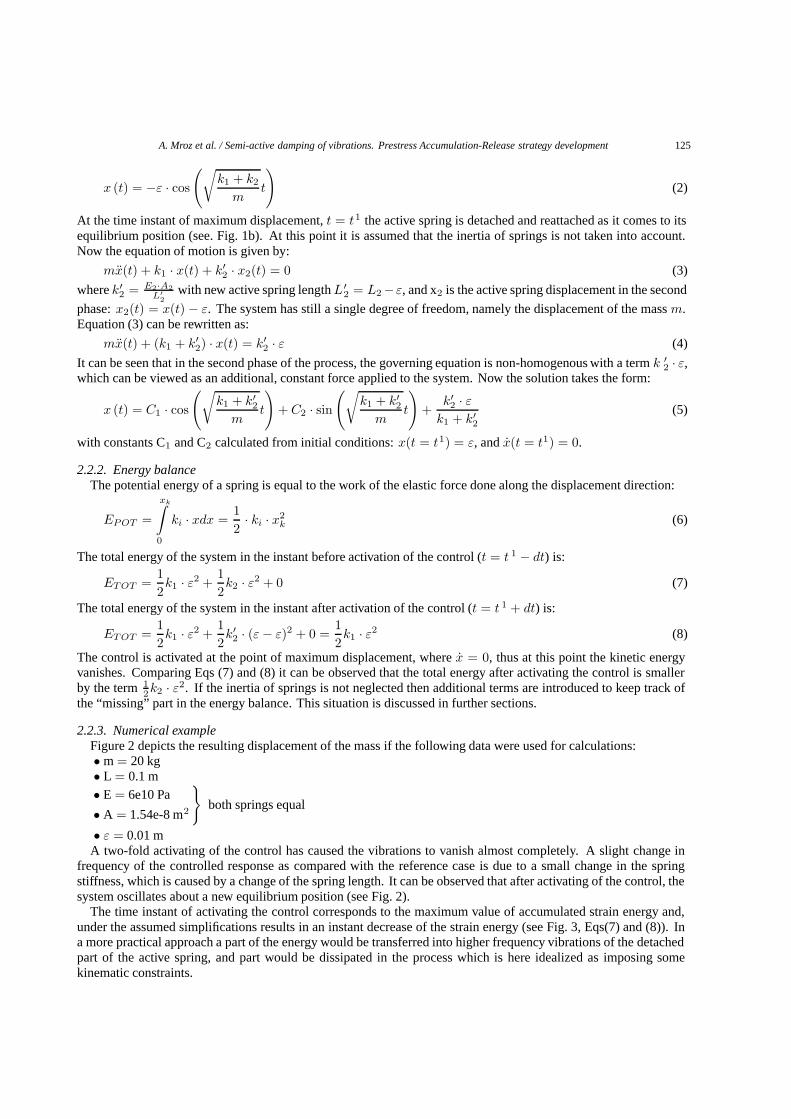
A. Mroz et al. / Semi-active damping of vibrations. Prestress Accumulation-Release strategy development 125
x (t) = −ε · cos
(√k1 + k2
mt
)(2)
At the time instant of maximum displacement, t = t1 the active spring is detached and reattached as it comes to itsequilibrium position (see. Fig. 1b). At this point it is assumed that the inertia of springs is not taken into account.Now the equation of motion is given by:
mx(t) + k1 · x(t) + k′2 · x2(t) = 0 (3)
where k′2 = E2·A2
L′2
with new active spring length L′2 = L2−ε, and x2 is the active spring displacement in the second
phase: x2(t) = x(t) − ε. The system has still a single degree of freedom, namely the displacement of the mass m.Equation (3) can be rewritten as:
mx(t) + (k1 + k′2) · x(t) = k′
2 · ε (4)
It can be seen that in the second phase of the process, the governing equation is non-homogenous with a term k ′2 · ε,
which can be viewed as an additional, constant force applied to the system. Now the solution takes the form:
x (t) = C1 · cos
(√k1 + k′
2
mt
)+ C2 · sin
(√k1 + k′
2
mt
)+
k′2 · ε
k1 + k′2
(5)
with constants C1 and C2 calculated from initial conditions: x(t = t1) = ε, and x(t = t1) = 0.
2.2.2. Energy balanceThe potential energy of a spring is equal to the work of the elastic force done along the displacement direction:
EPOT =
xk∫0
ki · xdx =12· ki · x2
k (6)
The total energy of the system in the instant before activation of the control (t = t 1 − dt) is:
ETOT =12k1 · ε2 +
12k2 · ε2 + 0 (7)
The total energy of the system in the instant after activation of the control (t = t 1 + dt) is:
ETOT =12k1 · ε2 +
12k′2 · (ε − ε)2 + 0 =
12k1 · ε2 (8)
The control is activated at the point of maximum displacement, where x = 0, thus at this point the kinetic energyvanishes. Comparing Eqs (7) and (8) it can be observed that the total energy after activating the control is smallerby the term 1
2k2 · ε2. If the inertia of springs is not neglected then additional terms are introduced to keep track ofthe “missing” part in the energy balance. This situation is discussed in further sections.
2.2.3. Numerical exampleFigure 2 depicts the resulting displacement of the mass if the following data were used for calculations:• m = 20 kg• L = 0.1 m• E = 6e10 Pa
• A = 1.54e-8 m2
}both springs equal
• ε = 0.01 mA two-fold activating of the control has caused the vibrations to vanish almost completely. A slight change in
frequency of the controlled response as compared with the reference case is due to a small change in the springstiffness, which is caused by a change of the spring length. It can be observed that after activating of the control, thesystem oscillates about a new equilibrium position (see Fig. 2).
The time instant of activating the control corresponds to the maximum value of accumulated strain energy and,under the assumed simplifications results in an instant decrease of the strain energy (see Fig. 3, Eqs(7) and (8)). Ina more practical approach a part of the energy would be transferred into higher frequency vibrations of the detachedpart of the active spring, and part would be dissipated in the process which is here idealized as imposing somekinematic constraints.

126 A. Mroz et al. / Semi-active damping of vibrations. Prestress Accumulation-Release strategy development
Fig. 2. Resulting mass displacement; control triggered twice.
Fig. 3. Energy balance.
2.3. A case with the inertia of the active spring considered
2.3.1. IntroductionAs stated before, detaching of the active spring results in converting the accumulated strain energy into kinetic
energy, which can be dissipated from the system during reattachment of the spring. This whole process was idealizedin the previous section by imposing proper initial conditions, which resulted in an instant decrease in energy ofthe system. In practice, part of the released strain energy is dissipated by a device that reattaches the spring andthe remaining part introduces higher frequency vibrations which can be, however, easily suppressed with naturaldamping of the system.
In the present analysis, the control device is idealized with imposing/releasing of local constraints between thegeometrical point of mass m and any point along the active spring. The mass of active spring is concentrated at itsend and in the middle (see Fig. 4).
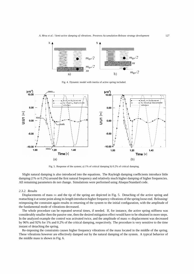
A. Mroz et al. / Semi-active damping of vibrations. Prestress Accumulation-Release strategy development 127
Fig. 4. Dynamic model with inertia of active spring included.
Fig. 5. Response of the system; a) 1% of critical damping b) 0.2% of critical damping.
Slight natural damping is also introduced into the equations. The Rayleigh damping coefficients introduce littledamping (1% or 0.2%) around the first natural frequency and relatively much higher damping of higher frequencies.All remaining parameters do not change. Simulations were performed using Abaqus/Standard code.
2.3.2. ResultsDisplacements of mass m and the tip of the spring are depicted in Fig. 5. Detaching of the active spring and
reattaching it at some point along its length introduces higher frequency vibrations of the spring loose end. Releasing/reimposing the constraint again results in returning of the system to the initial configuration, with the amplitude ofthe fundamental mode of vibrations decreased.
The whole procedure can be repeated several times, if needed. If, for instance, the active spring stiffness wasconsiderably smaller then the passive one, then the desired mitigation effect would have to be obtained in more steps.In the analyzed example the control was activated twice, and the amplitude of mass m displacement was decreasedby 96% and 92% for 1% and 0.2% of the critical damping, respectively. The procedure is very sensitive to the timeinstant of detaching the spring.
Re-imposing the constraints causes higher frequency vibrations of the mass located in the middle of the spring.These vibrations however are effectively damped out by the natural damping of the system. A typical behavior ofthe middle mass is shown in Fig. 6.

128 A. Mroz et al. / Semi-active damping of vibrations. Prestress Accumulation-Release strategy development
Fig. 6. Middle mass response with indicated points corresponding to activating control.
All non-zero forms of energy can be viewed in Fig. 7. Steep, exponential decline in the sum of potential andkinetic energy graph is due to the viscous dissipation which increases with the increase of vibration velocity. Thehighest vibration velocity follows the imposing/ releasing of the constraints. The viscous dissipation is due to thenatural damping of the system.
3. Delamination of a layered beam
3.1. PAR strategy for layered beams
The strategy of releasing the accumulated strain energy in order to dissipate it can, in theory, be effectively usedfor various types of structures. If a layered beam is considered as shown in Fig. 8, the idea of adaptation would be asfollows. First, at the point of maximum deflection two layers are disconnected resulting in the instant dislocation oflayers (1’ in Fig. 8a). The dislocation is “frozen” if the layers are reconnected. This yields introduction of an elasticforce that opposes the further vibration of the structure (2 in Fig. 8a). Then, near the equilibrium position layers aredisconnected/ reconnected again in order to return to the initial configuration. The whole sequence can be repeateduntil the desired effect is obtained.
A similar effect of response mitigation can be obtained if a truss structure is considered with a detachable element(see Fig. 8b). Applying the same methodology for control, the axial strain accumulated in an active element can bereleased as the element is disconnected at one of its ends.
It is worth mentioning that in both cases only one active member is required in order to mitigate the fundamentalmode of vibration.
3.2. Numerical example – simply supported beam
3.2.1. Numerical modelA simply supported, two-layered beam with the span of 15.6 m is considered. Bending stiffness of each layer is
EI = 2.218 × 10⁶ Nm2. Material damping of 1% of critical damping is assumed around the 1st natural frequency.Layers are permanently connected together at the left support. It is assumed that there is a device at the right supportcapable of instantly disconnecting or sticking the layers. Along the beam length the distance between layers remains

A. Mroz et al. / Semi-active damping of vibrations. Prestress Accumulation-Release strategy development 129
Fig. 7. a) sum of strain and kinetic energy b) viscous dissipation due to natural damping c) loss of kinetic energy during imposing constrains.
Fig. 8. PAR strategy for a cantilever beam.
the same, whereas the frictionless, relative movement of layers is possible in the direction parallel to the beam axis.Considered beam model is depicted in Fig. 9.
The numerical simulations were performed using Abaqus Standard code. Elastic layers were modeled with 3-node

130 A. Mroz et al. / Semi-active damping of vibrations. Prestress Accumulation-Release strategy development
Fig. 9. Assumed model of layered beam.
Fig. 10. Vertical displacement of the middle of beam.
quadratic beam elements. Constant distance between layers was obtained with Slot type connector elements spacedevery 0.90 m. The layers’ relative displacement was controlled by means of one active connector element located atone of the beam ends. The active connector element’s relative motion was allowed or constrained using a Fortranprocedure. The on/off control was based on the current deformation of the middle of the span.
3.2.2. ResultsIn the first step an initial displacement of 16 cm was applied to the model and free vibrations of the system were
calculated for the reference case. Then calculations were repeated with the control procedures added. The verticaldisplacement of the middle of the span is shown in Fig. 10.
It can be observed that 95% of the vibration amplitude is damped out after two cycles of vibration. The relativedisplacement between layers’ ends shown on the picture is magnified 10 times. The attaching process creates animpact followed by higher frequency, local vibrations which are manifested with longitudinal vibrations of layers.These vibrations are successfully damped out with the structural damping.
After two cycles of disconnection/ reconnection of layers, the vibration of the first mode is considerably mitigated,while the higher modes become dominant. The second sequence of control activation is triggered close to themaximum accumulated strain, at the point where the deformation shape is of the first mode (see Fig. 11a). In orderto maximize the effect, the “frozen” dislocation of layers should be maximized. Therefore the deflection peak, atwhich the control is to be activated should be chosen carefully, avoiding unfavorable deformation shapes, f.e. ofthe third mode (see Fig. 11b). In order to suppress higher modes of vibration more active members are required,thus more interfering in the structural integrity would be needed. Such a case could still be reasonable for someapplications, but it has not been considered in this paper. For many applications, especially in slender structures, themajority of the vibration energy is transferred in the first few modes, making the fundamental mode mitigation animportant task.
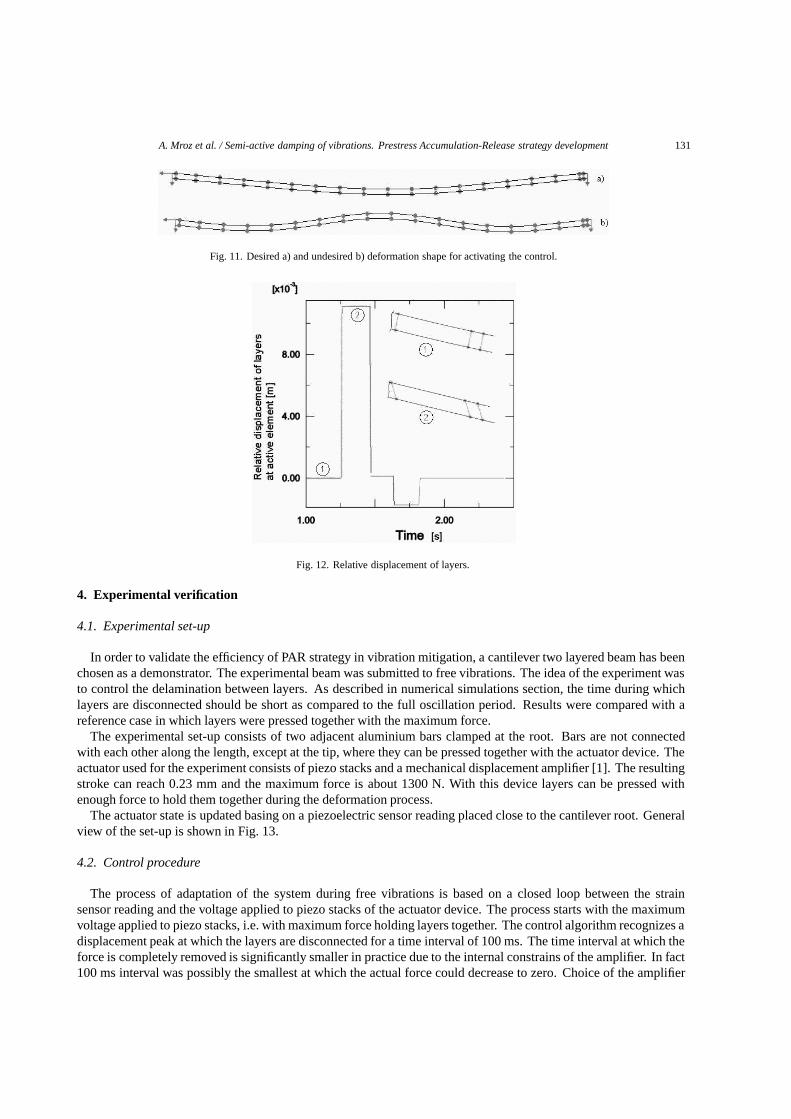
A. Mroz et al. / Semi-active damping of vibrations. Prestress Accumulation-Release strategy development 131
Fig. 11. Desired a) and undesired b) deformation shape for activating the control.
Fig. 12. Relative displacement of layers.
4. Experimental verification
4.1. Experimental set-up
In order to validate the efficiency of PAR strategy in vibration mitigation, a cantilever two layered beam has beenchosen as a demonstrator. The experimental beam was submitted to free vibrations. The idea of the experiment wasto control the delamination between layers. As described in numerical simulations section, the time during whichlayers are disconnected should be short as compared to the full oscillation period. Results were compared with areference case in which layers were pressed together with the maximum force.
The experimental set-up consists of two adjacent aluminium bars clamped at the root. Bars are not connectedwith each other along the length, except at the tip, where they can be pressed together with the actuator device. Theactuator used for the experiment consists of piezo stacks and a mechanical displacement amplifier [1]. The resultingstroke can reach 0.23 mm and the maximum force is about 1300 N. With this device layers can be pressed withenough force to hold them together during the deformation process.
The actuator state is updated basing on a piezoelectric sensor reading placed close to the cantilever root. Generalview of the set-up is shown in Fig. 13.
4.2. Control procedure
The process of adaptation of the system during free vibrations is based on a closed loop between the strainsensor reading and the voltage applied to piezo stacks of the actuator device. The process starts with the maximumvoltage applied to piezo stacks, i.e. with maximum force holding layers together. The control algorithm recognizes adisplacement peak at which the layers are disconnected for a time interval of 100 ms. The time interval at which theforce is completely removed is significantly smaller in practice due to the internal constrains of the amplifier. In fact100 ms interval was possibly the smallest at which the actual force could decrease to zero. Choice of the amplifier
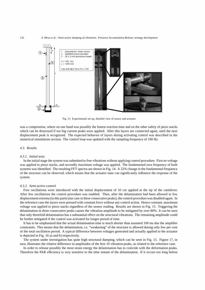
132 A. Mroz et al. / Semi-active damping of vibrations. Prestress Accumulation-Release strategy development
Fig. 13. Experimental set-up, detailed view of sensor and actuator.
was a compromise, where on one hand was possibly the fastest reaction time and on the other safety of piezo stackswhich can be destroyed if too big current peaks were applied. After this layers are connected again, until the nextdisplacement peak is recognized. The expected behavior of layers during activating control was described in thenumerical simulations section. The control loop was updated with the sampling frequency of 100 Hz.
4.3. Results
4.3.1. Initial testsIn the initial stage the system was submitted to free vibrations without applying control procedure. First no voltage
was applied to piezo stacks, and secondly maximum voltage was applied. The fundamental own frequency of bothsystems was identified. The resulting FFT spectra are shown in Fig. 14. A 22% change in the fundamental frequencyof the structure can be observed, which means that the actuator state can significantly influence the response of thesystem.
4.3.2. Semi-active controlFree oscillations were introduced with the initial displacement of 10 cm applied at the tip of the cantilever.
After few oscillations the control procedure was enabled. Then, after the delamination had been allowed in fewdisplacement extrema (in this particular case in three consecutive peaks), the control procedure was disabled again. Inthe reference case the layers were pressed with constant force without any control action. Hence constant, maximumvoltage was applied to piezo stacks regardless of the sensor reading. Results are shown in Fig. 15. Triggering thedelamination in three consecutive peaks causes the vibration amplitude to be mitigated by over 80%. It can be seenthat only threefold delamination has a substantial effect on the structural vibrations. The remaining amplitude couldbe further mitigated if the control was activated for longer period of time.
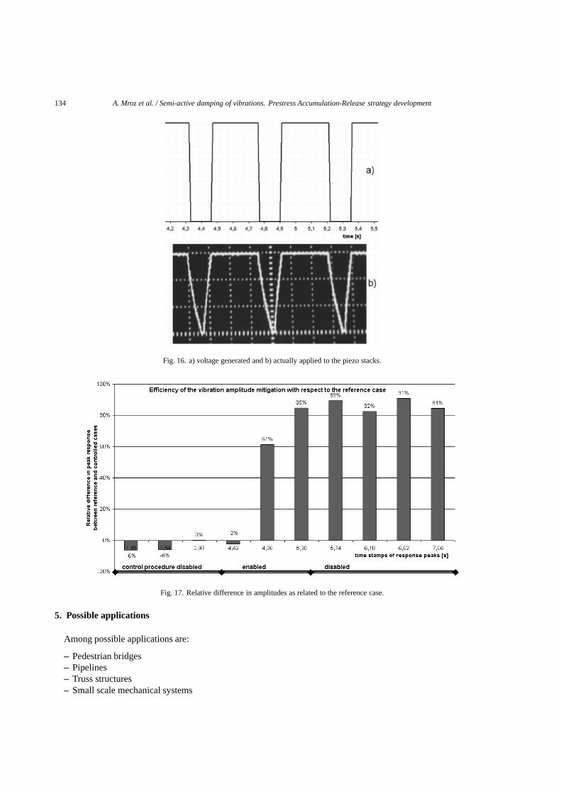
It has to be emphasized that the actual delamination time is much shorter than assumed 100 ms due the amplifierconstraints. This means that the delamination, i.e. “weakening” of the structure is allowed during only few per centof the total oscillation period. A typical difference between voltages generated and actually applied to the actuatoris depicted in Fig. 16 a) and b) respectively.
The system under investigation has quite high structural damping, which can be seen in Fig. 15. Figure 17, inturn, illustrates the relative difference in amplitudes of the first 10 vibration peaks, as related to the reference case.
In order to release possibly the most strain energy the delamination has to coincide with the deformation peaks.Therefore the PAR efficiency is very sensitive to the time instant of the delamination. If it occurs too long before

A. Mroz et al. / Semi-active damping of vibrations. Prestress Accumulation-Release strategy development 133
Fig. 14. 1st eigen frequency shift between disconnected and connected layers.
Fig. 15. Time history response of the system.
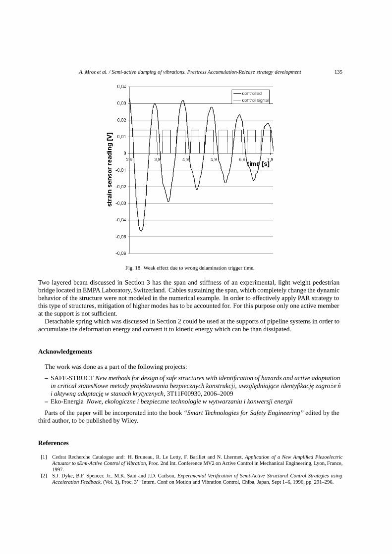
or after the maximum deflection then the obtained response mitigation is less significant. If, in the worst case thedelamination occurs around the equilibrium position of the cantilever then there is no effect at all since there wasno deformation incompabilities between layers which could be “frozen”. Figure 18 shows no damping effect due towrong delamination trigger time.
134 A. Mroz et al. / Semi-active damping of vibrations. Prestress Accumulation-Release strategy development
Fig. 16. a) voltage generated and b) actually applied to the piezo stacks.
Fig. 17. Relative difference in amplitudes as related to the reference case.
5. Possible applications
Among possible applications are:
– Pedestrian bridges– Pipelines– Truss structures– Small scale mechanical systems
A. Mroz et al. / Semi-active damping of vibrations. Prestress Accumulation-Release strategy development 135
Fig. 18. Weak effect due to wrong delamination trigger time.
Two layered beam discussed in Section 3 has the span and stiffness of an experimental, light weight pedestrianbridge located in EMPA Laboratory, Switzerland. Cables sustaining the span, which completely change the dynamicbehavior of the structure were not modeled in the numerical example. In order to effectively apply PAR strategy tothis type of structures, mitigation of higher modes has to be accounted for. For this purpose only one active memberat the support is not sufficient.
Detachable spring which was discussed in Section 2 could be used at the supports of pipeline systems in order toaccumulate the deformation energy and convert it to kinetic energy which can be than dissipated.
Acknowledgements
The work was done as a part of the following projects:
– SAFE-STRUCT New methods for design of safe structures with identification of hazards and active adaptationin critical statesNowe metody projektowania bezpiecznych konstrukcji, uwzgledniajace identyfikacje zagroze ni aktywna adaptacje w stanach krytycznych, 3T11F00930, 2006–2009
– Eko-Energia Nowe, ekologiczne i bezpieczne technologie w wytwarzaniu i konwersji energii
Parts of the paper will be incorporated into the book “Smart Technologies for Safety Engineering” edited by thethird author, to be published by Wiley.
References
[1] Cedrat Recherche Catalogue and: H. Bruneau, R. Le Letty, F. Barillet and N. Lhermet, Application of a New Amplified PiezoelectricActuator to sEmi-Active Control of Vibration, Proc. 2nd Int. Conference MV2 on Active Control in Mechanical Engineering, Lyon, France,1997.
[2] S.J. Dyke, B.F. Spencer, Jr., M.K. Sain and J.D. Carlson, Experimental Verification of Semi-Active Structural Control Strategies usingAcceleration Feedback, (Vol. 3), Proc. 3’" Intern. Conf on Motion and Vibration Control, Chiba, Japan, Sept 1–6, 1996, pp. 291–296.

136 A. Mroz et al. / Semi-active damping of vibrations. Prestress Accumulation-Release strategy development
[3] L. Gaul, R. Nitsche and D. Sachau, Semi-Active Vibration Control of Flexible Structures, Proc. of the EUROMECH 373 Colloquium onModelling and Control of Adaptive Mechanical Structure, 1998, Magdeburg, Germany.
[4] J. Holnicki-Szulc and Z. Marzec, Adaptive Structures with Semi-Active Interfac, Proc. of the EUROMECH 373 Colloquium on Modellingand Control of Adaptive Mechanica Structures, 1998, Magdeburg, Germany.
[5] F. dell’Isola and S. Vidoli, Damping of bending waves in truss beams by electrical transmission lines with PZT actuators, Archive ofApplied Mechanics 68 (1998), 626–636.
[6] D.C. Kamopp, M.J. Crosby and R.A. Harwood, Vibration control using semi active force generation, Jour Of Engineering For Industry,ASME 96(2) (1974), 619–626.
[7] T. Kobori, M. Takahashi, T. Nasu and N. Niwa, Seismic response controlled structure with active variable stiffness systems, EarthquakeEngineering and Structural Dynamics 22 (1993), 925–941.
[8] G.G. Lee, Z. Liang and M. Tong, Development of a Semi-Active Structural Control System. In Research progress and Accomplishments1997–1999, Multidisciplinary Center for Earthquake Engineering Research MCEER, SUNY at Buffalo, NY, USA, July 1999.
[9] D.F. Ledezma-Ramirez, N.S. Ferguson and M.J. Brennan, Vibration decay using on-off stiffness control, Proc. Of the ISMA InternationalConference on Noise and Vibration Engineering, Leuven, Belgium, September 2006.
[10] Z. Marzec, J. Holnicki-Szulc and F. Lopez-Almansa, Strategy of Impulse Release of Strain Energy for Damping of Vibration, Proc. NATOARW Smart Structures’98, 1998, Pultusk, Poland.
[11] W.N. Patten, J. Sun, G. Li, J. Kuehn and G. Song, Field test of an intelligent stiffener for bridges at the 1–35 Walnut Creek Bridge,Earthquake Engineering and Structural Dynamics 28(2) (1999), 109–126.
[12] A. Ruangrassamee and K. Kawashima, Semi-Active Control of Bridges with use of Magnetorheological Damper, Proc. of 12th EuropeanConference on Earthquake Engineering, London England, Sept. 2002, paper n. 171, CD-ROM.
[13] M.D. Symans and M.C. Constantinou, Semi-Active control systems for seismic protection of structures: a state-of-the-art review,Engineering Structures 21(6) (1999), 469–487.
[14] M.D. Symans, G.J. Madden and N. Wongprasert, Experimental Study of an Adaptive Base Isolation System for Buildings, Proc. of 12thWorld Conf on Earthquake Eng, 12WCEE, Auckland, New Zealand, 30 Jan.-4 Feb. 2000, paper n.1965, CD-ROM.

International Journal of
AerospaceEngineeringHindawi Publishing Corporationhttp://www.hindawi.com Volume 2010
RoboticsJournal of
Hindawi Publishing Corporationhttp://www.hindawi.com Volume 2014
Hindawi Publishing Corporationhttp://www.hindawi.com Volume 2014
Active and Passive Electronic Components
Control Scienceand Engineering
Journal of
Hindawi Publishing Corporationhttp://www.hindawi.com Volume 2014
International Journal of
RotatingMachinery
Hindawi Publishing Corporationhttp://www.hindawi.com Volume 2014
Hindawi Publishing Corporation http://www.hindawi.com
Journal ofEngineeringVolume 2014
Submit your manuscripts athttp://www.hindawi.com
VLSI Design
Hindawi Publishing Corporationhttp://www.hindawi.com Volume 2014
Hindawi Publishing Corporationhttp://www.hindawi.com Volume 2014
Shock and Vibration
Hindawi Publishing Corporationhttp://www.hindawi.com Volume 2014
Civil EngineeringAdvances in
Acoustics and VibrationAdvances in
Hindawi Publishing Corporationhttp://www.hindawi.com Volume 2014
Hindawi Publishing Corporationhttp://www.hindawi.com Volume 2014
Electrical and Computer Engineering
Journal of
Advances inOptoElectronics
Hindawi Publishing Corporation http://www.hindawi.com
Volume 2014
The Scientific World JournalHindawi Publishing Corporation http://www.hindawi.com Volume 2014
SensorsJournal of
Hindawi Publishing Corporationhttp://www.hindawi.com Volume 2014
Modelling & Simulation in EngineeringHindawi Publishing Corporation http://www.hindawi.com Volume 2014
Hindawi Publishing Corporationhttp://www.hindawi.com Volume 2014
Chemical EngineeringInternational Journal of Antennas and
Propagation
International Journal of
Hindawi Publishing Corporationhttp://www.hindawi.com Volume 2014
Hindawi Publishing Corporationhttp://www.hindawi.com Volume 2014
Navigation and Observation
International Journal of
Hindawi Publishing Corporationhttp://www.hindawi.com Volume 2014
DistributedSensor Networks
International Journal of