self propelled walk behind sodcutter parts manual
TRANSCRIPT

PAR
TS M
AN
UA
L
MA
N 4
1646
45R
ev. A
01-
2010
Orig
inal
Lan
guag
e In
stru
ctio
ns
OPERATOR'S MANUAL 4164644
SELF PROPELLED WALK BEHIND SODCUTTER
744844GJR SODCUTTER 6HP B&S 12"
744845GJR SODCUTTER 6HP B&S 18"
744944CJR SODCUTTER 5.5HP HONDA 12"
744945CJR SODCUTTER 5.5HP HONDA 18"
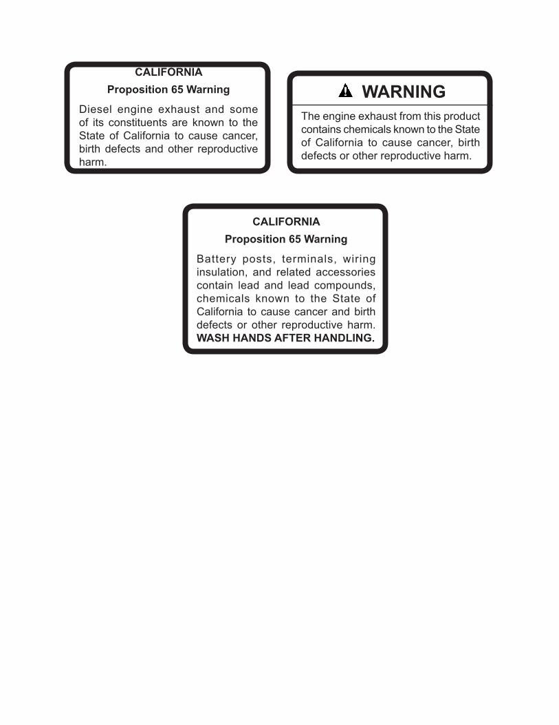
CALIFORNIAProposition 65 Warning
Diesel engine exhaust and some of its constituents are known to the State of California to cause cancer, birth defects and other reproductive harm.
WARNINGThe engine exhaust from this product contains chemicals known to the State of California to cause cancer, birth defects or other reproductive harm.
CALIFORNIAProposition 65 Warning
Battery posts, terminals, wiring insulation, and related accessories contain lead and lead compounds, chemicals known to the State of California to cause cancer and birth defects or other reproductive harm. WASH HANDS AFTER HANDLING.

1
JR SODCUTTER
01/2010
IMPORTANT MESSAGEThank you for purchasing this Schiller Grounds Care, Inc. product. You have purchased a world class product, one of the best designed and built anywhere.
This machine comes with aN Operation and Parts Manual. The useful life and good service you receive from this machine depends to a large extent on how well you read and understand this manual. Treat your machine properly, lubricate and adjust it as instructed, and it will give you many years of reliable service.
Your safe use of this Schiller Grounds Care, Inc. product is one of our prime design objectives. Many safety features are built in, but we also rely on your good sense and care to achieve accident-free operation. For best protection, study the manual thoroughly. Learn the proper operation of all controls. Observe all safety precau-tions. Follow all instructions and warnings completely. Do not remove or defeat any safety features. Make sure those who operate this machine are as well informed and careful in its use as you are.
See a Schiller Grounds Care, Inc. dealer for any service or parts needed. Schiller Grounds Care, Inc. service ensures that you continue to receive the best results possible from Schiller Grounds Care, Inc. products. You can trust Schiller Grounds Care, Inc. replacement parts because they are manufactured with the same high precision and quality as the original parts.
Schiller Grounds Care, Inc. designs and builds its equipment to serve many years in a safe and productive man-ner. For longest life, use this machine only as directed in the manual, keep it in good repair and follow safety warnings and instructions. You'll always be glad you did.
Schiller Grounds Care, Inc.One Bob Cat Lane
Johnson Creek, WI 53038-0469
TABLE OF CONTENTS .............................................................................................. PAGESAFETY .........................................................................................................................................................2,3SET-UP .............................................................................................................................................................4ADJUSTMENTS ............................................................................................................................................5-7MAINTENANCE/SERVICE ..........................................................................................................................8-16STORAGE ......................................................................................................................................................17TROUBLESHOOTING ...................................................................................................................................18SPECIFICATIONS ..........................................................................................................................................19PARTS SECTION ...........................................................................................................................................20DRIVE ASSEMBLY AND SIDE COVER ...................... FIGURE 1 ........................................................... 20,21MUFFLER GUARDS ................................................... FIGURE 2 ............................................................ 22,23GEAR CASE................................................................ FIGURE 3 ........................................................... 24,25SIDE ARMS, PITMAN ARMS, AND HANDLES ........... FIGURE 4 ............................................................ 26,27HANDLEBAR ASSEMBLY ........................................... FIGURE 5 ............................................................ 28,29MOLE BLADE KIT ....................................................... FIGURE 6 ............................................................ 30,31TRENCHING KIT ......................................................... FIGURE 7 ........................................................... .32,33
2
JR SODCUTTER
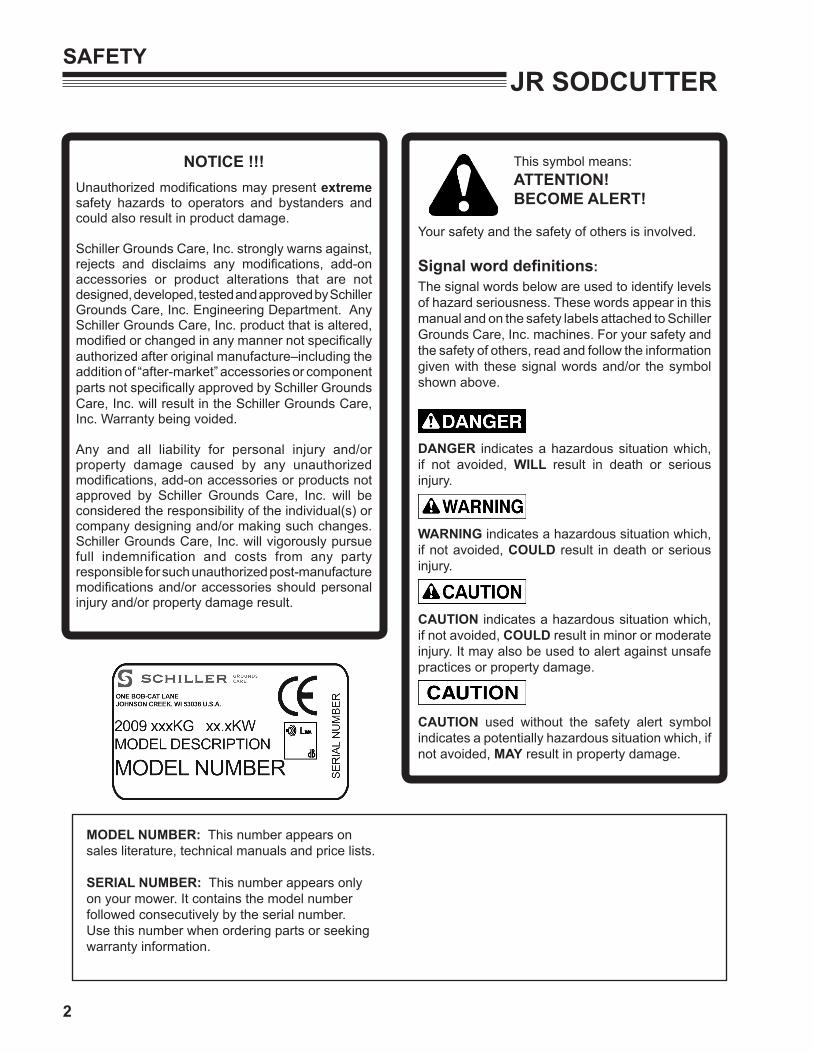
MODEL NUMBER: This number appears on sales literature, technical manuals and price lists.
SERIAL NUMBER: This number appears only on your mower. It contains the model number followed consecutively by the serial number. Use this number when ordering parts or seeking warranty information.
SAFETY
NOTICE !!!Unauthorized modifications may present extreme safety hazards to operators and bystanders and could also result in product damage.
Schiller Grounds Care, Inc. strongly warns against, rejects and disclaims any modifications, add-on accessories or product alterations that are not designed, developed, tested and approved by Schiller Grounds Care, Inc. Engineering Department. Any Schiller Grounds Care, Inc. product that is altered, modified or changed in any manner not specifically authorized after original manufacture–including the addition of “after-market” accessories or component parts not specifically approved by Schiller Grounds Care, Inc. will result in the Schiller Grounds Care, Inc. Warranty being voided.
Any and all liability for personal injury and/or property damage caused by any unauthorized modifications, add-on accessories or products not approved by Schiller Grounds Care, Inc. will be considered the responsibility of the individual(s) or company designing and/or making such changes. Schiller Grounds Care, Inc. will vigorously pursue full indemnification and costs from any party responsible for such unauthorized post-manufacture modifications and/or accessories should personal injury and/or property damage result.
This symbol means: ATTENTION! BECOME ALERT!
Your safety and the safety of others is involved.
Signal word definitions:The signal words below are used to identify levels of hazard seriousness. These words appear in this manual and on the safety labels attached to Schiller Grounds Care, Inc. machines. For your safety and the safety of others, read and follow the information given with these signal words and/or the symbol shown above.
DANGER indicates a hazardous situation which, if not avoided, WILL result in death or serious injury.
WARNING indicates a hazardous situation which, if not avoided, COULD result in death or serious injury.
CAUTION indicates a hazardous situation which, if not avoided, COULD result in minor or moderate injury. It may also be used to alert against unsafe practices or property damage.
CAUTION used without the safety alert symbol indicates a potentially hazardous situation which, if not avoided, MAY result in property damage.

3
JR SODCUTTERSAFETY
Fuel- Petrol (gasoline) and
diesel fuels are flammable; petrol (gasoline) vapors are explosive. Use extra care when handling.
- Store only in containers specifically designed for fuel.
- When refueling or checking fuel level: - Stop the engine and allow to cool; - Do not smoke; - Refuel outdoors only; - Use a funnel; - Do not overfill; - If fuel is spilled, do not attempt to start the
engine until the spill is cleaned up and vapors have cleared.
- Replace caps on fuel containers and tanks securely.
Sparks from static electricity can start fires or cause explosions. Flowing fuel can generate static electric-ity. To prevent static electricity sparks:- Keep fuel containers electrically grounded. Do
not fill containers in a vehicle or on a truck or trailer bed with a plastic liner. Fill containers on the ground away from the vehicle.
- When practical, remove petrol (gas) powered equipment from the truck or trailer and refuel it on the ground. If equipment must be refueled on the truck or trailer, refuel from a portable container rather than a dispenser nozzle.
- Keep the dispenser nozzle in contact with the rim of the fuel tank or container opening until fueling is complete. Do not use a nozzle lock-open device.
MAINTENANCE SAFETYIn general- Maintain machine according to manufacturer's
schedule and instructions for maximum safety and best results.
- Park machine on level ground. - Never allow untrained personnel to service ma-
chine. - Guards should only be removed by qualified
maintenance technician for manintenance/ser-vice. Replace when work is complete.
- Adjust or repair only after the engine has been stopped and the blade has stopped moving.
- Disconnect spark plug wire(s) before doing any maintenance.
- Replace parts if worn, damaged or faulty. For best results, always replace with parts recommended by the manufacturer.
- Do not dismantle the machine without releasing or restraining forces which may cause parts to move suddenly.
- Provide adequate support, e.g. jack stands for lifted machine or parts if working beneath.
- Do not put hands or feet near or under rotating parts.
- Clean up spilled oil or fuel thoroughly.- Replace faulty mufflers.- To reduce fire hazards, keep the engine, muf-
fler, and fuel storage area free of grass, leaves, debris buildup or grease.
Blades The sod cutter blade is sharp
and can cut. Use extra cau-tion when handling. Remove obstructions with care. Wrap the blade or wear gloves.
- Only replace blade. Never straighten or weld.
- Keep other persons away from blades.
WARNING
WARNING
4
JR SODCUTTERSET-UP
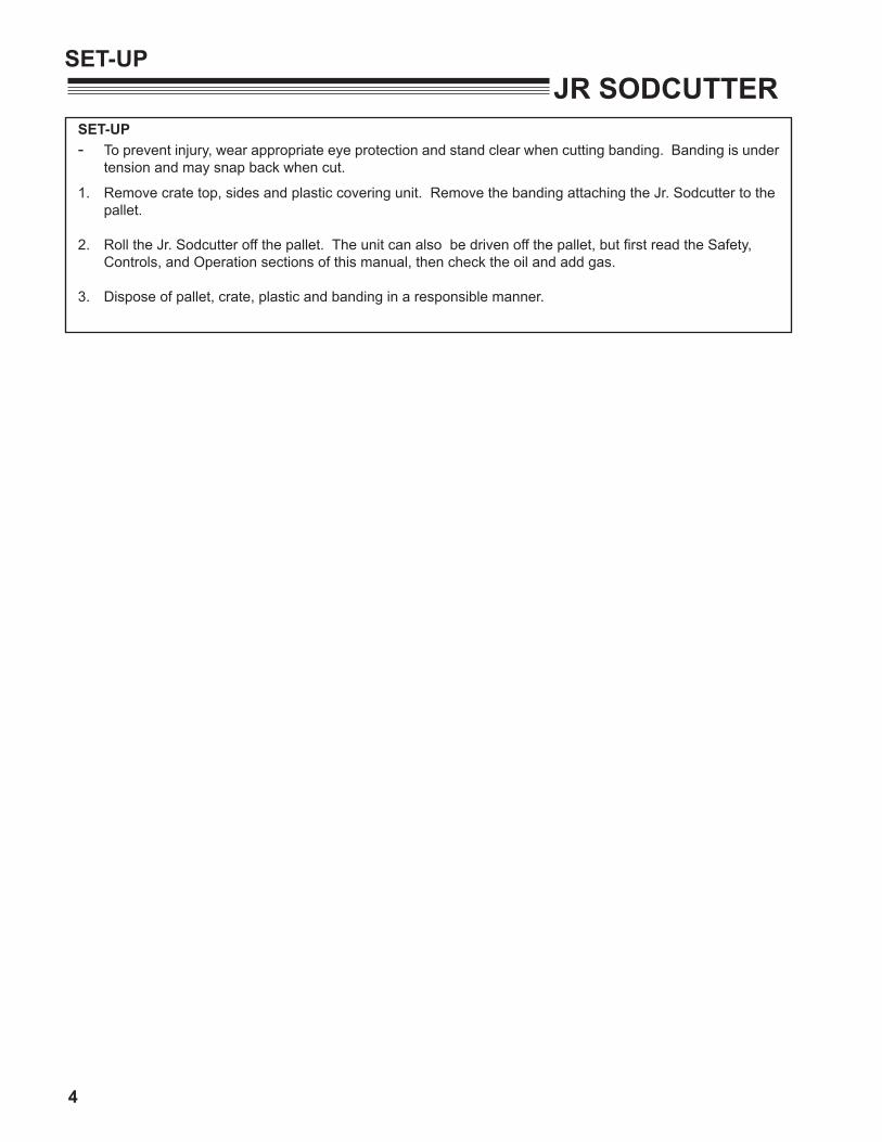
SET-UP- To prevent injury, wear appropriate eye protection and stand clear when cutting banding. Banding is under
tension and may snap back when cut.
1. Remove crate top, sides and plastic covering unit. Remove the banding attaching the Jr. Sodcutter to the pallet.
2. Roll the Jr. Sodcutter off the pallet. The unit can also be driven off the pallet, but first read the Safety, Controls, and Operation sections of this manual, then check the oil and add gas.
3. Dispose of pallet, crate, plastic and banding in a responsible manner.

5
JR SODCUTTERADJUSTMENTS
DRIvE BELT ADJUSTMENT
Keep belt free of oil and dirt, and adjusted to proper tension at all times.
Belt tension is adjusted by loosening four (4) engine mounting bolts and shifting engine on the base.
Belt tension is correct when the distance between the roll pin and sleeve on the master clutch rod is 1" to 1 1/4" (25-30mm) when the master clutch is engaged.
ENGINE
ENGINEBOLT
ENGINEPULLEY
BLOCKENGINEMOUNT PLATE
1" (25.4 mm)
IDLERPULLEY
BELTDRIVEPULLEY
BRAKE BAND ADJUSTMENT
When adjusted properly:- With the Master Clutch Control Lever engaged, the brake band is not braking the large drive pulley.- When the Master Clutch Control Lever is disen-gaged, there will be some brakig occuring on the large drive pulley.- When the Master Clutch Control Lever is disen-gaged, and pulled back firmly, the brake will fully stop the large drive pulley.
1. For less braking, loosen the locknut, unscrew the adjusting screw, then retighten the locknut.
2. For more braking, loosen the locknut, turn the adjusting screw in, then retighten the locknut.
Start the machine, and check for proper operation. Readjust if necessary. IF the engine kills when engaging the Master clutch Control Lever, the brake may be set too tight.
Brake Band Lock Nut
Adjusting ScrewGuard Support Rod
ADJUSTING DEPTH OF CUT
3/4" (20mm) is a good general starting depth of cut. Depth of cut can be varied from there depending on conditions and what you are trying to accomplish.
1. Make an initial depth setting. Park the machine on a hard surface. Loosen depth control locking lever E and lower depth control lever D until the blade rests on the surface.
2. Loosen the depth gauge lock E and set top of depth gauge G to the 3/4" (20mm) mark on the label. Tighten the depth gauge lock knob to secure the depth gauge setting.
3. Use your left hand to tip the machine forward while lowering the depth control lever D until the depth control crossbar hits the Depth Stop G. Tighten the locking lever E to lock in the depth setting, make a trial run in turf. Check the depth of cut.
4. Re-adjust the depth gauge G and depth control lever D if necessary.
NOTE: Numbers on depth gauge do not necessarily represent thickness of sod being cut. The numbers are useful as a reference for making changes.
6
Jr.Sodcutter
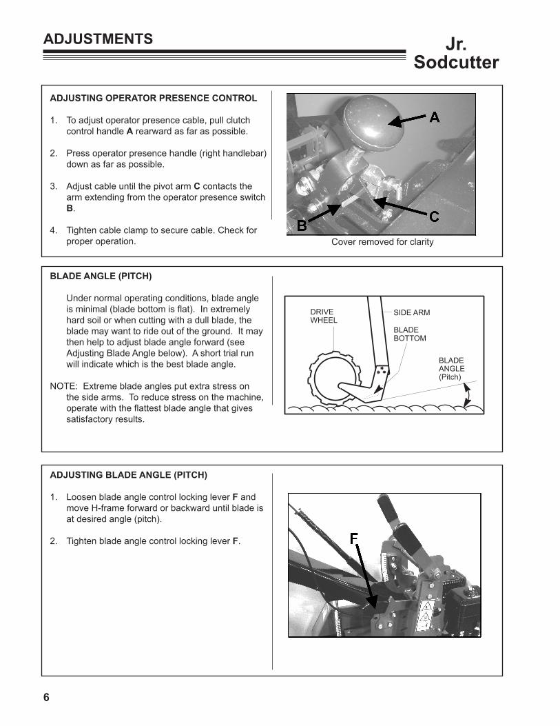
ADJUSTING OPERATOR PRESENCE CONTROL
1. To adjust operator presence cable, pull clutch control handle A rearward as far as possible.
2. Press operator presence handle (right handlebar) down as far as possible.
3. Adjust cable until the pivot arm C contacts the arm extending from the operator presence switch B.
4. Tighten cable clamp to secure cable. Check for proper operation.
ADJUSTMENTS
ADJUSTING BLADE ANGLE (PITCH)
1. Loosen blade angle control locking lever F and move H-frame forward or backward until blade is at desired angle (pitch).
2. Tighten blade angle control locking lever F.
SIDE ARMDRIVEWHEEL
BLADEBOTTOM
BLADEANGLE(Pitch)
BLADE ANGLE (PITCH)
Under normal operating conditions, blade angle is minimal (blade bottom is flat). In extremely hard soil or when cutting with a dull blade, the blade may want to ride out of the ground. It may then help to adjust blade angle forward (see Adjusting Blade Angle below). A short trial run will indicate which is the best blade angle.
NOTE: Extreme blade angles put extra stress on the side arms. To reduce stress on the machine, operate with the flattest blade angle that gives satisfactory results.
Cover removed for clarity

7
Jr. Sodcutter
HANDLE SUPPORT SPRINGThis spring S helps support the handle. If the four (4)isolator handle mounts are sagging or distorted, the twolocking adjustment nuts T can be tighted downward toincrease the spring force and raise the handle.
HANDLE STOP BOLTSThese two bolts Y limit the amount of handle movement. This prevents damage to the handle isolators, and providespositive control of the machine when extra effort is requiredto lift or turn. The rear stop bolt position is adjustable.. Loosen the two bolts X on the bolt centering plates on eachside and tighten with the stop bolts centered in the twohandle holes Z.
ADJUSTMENTS

8
Jr.Sodcutter
When replacement parts are required, use genuineSchiller Grounds Care, Inc. parts or parts with equivalent characteristics, including type, strength and material. Failure to do so may result inproduct malfunction and possible injury to the operator and/or bystanders.
Carbon monoxide present in the exhaust is an odorless and deadly gas. Never start or run the engine inside where exhaust fumes can collect.Provide enough fresh air to keep fumes from getting too strong.
Replace any warning decal that becomes illegibleimmediately.

9
Jr. Sodcutter
MAINTENANCE
DAILY MAINTENANCE
Operator Presence System For the engine to run, the Operator Presence
Lever must be held when the Master Clutch Control is engaged.
To Check:1. Start the engine and run at 1/2 throttle with the
master clutch disengaged.
2. Engage the master clutch holding the Operator Presence Lever. Release the operator presence lever and the engine should stop.
Repair the machine before using if the Operator Presence System does not kill the engine.
Blades: Check for damage. Replace any broken, cracked
or otherwise damaged blades. Do not weld or straighten blades. Replace or sharpen dull blades. See sharpening instructions.
Hardware: Tighten any nuts and bolts that are found loose.
Replace any broken or missing cotter pins. Repair any other problems before operating.
Engine: See engine manual for oil change intervals and
oil specifications. See engine manual for air cleaner service intervals and service procedure.
Lubrication:
The gear case is initially filled with 3 1/2 pints (1.7 L) of EP 140 Gear Lube. Do not add to this amount unless oil is changed or lost through leakage. Gear case drain plug D.
On all pressurized lubrication fittings use a good
grade of Lithium Based lubricant.
The Jr. Sodcutter has 6 lubrication fittings. Lubricate pitman arms (1 each side) and side arms (1 each side) after every 4 hours of use.
Lubricate side arm pivots (1 each side - top of unit) after every 8 hours of use.
Check gear case lubricant level using dipstick E located on top of gear case. Check lube with dipstick sitting on threads, do not screw in.
10
Jr.Sodcutter
MAINTENANCE
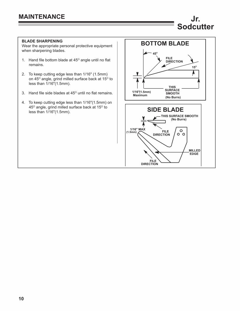
BLADE SHARPENINGWear the appropriate personal protective equipment when sharpening blades.
1. Hand file bottom blade at 45O angle until no flat remains.
2. To keep cutting edge less than 1/16" (1.5mm) on 45O angle, grind milled surface back at 15O to less than 1/16"(1.5mm).
3. Hand file side blades at 45O until no flat remains.
4. To keep cutting edge less than 1/16"(1.5mm) on 45O angle, grind milled surface back at 15O to less than 1/16"(1.5mm).
THIS1/16" Maximum
45O
15O
FILEDIRECTION
SURFACE SMOOTH(No Burrs)
BOTTOM BLADE
(1.5mm)
MILLED EDGE
FILEDIRECTION
1/16" MAX
THIS SURFACE SMOOTH(No Burrs)
FILEDIRECTION
SIDE BLADE
(1.5mm)
11
Jr. Sodcutter
MAINTENANCE
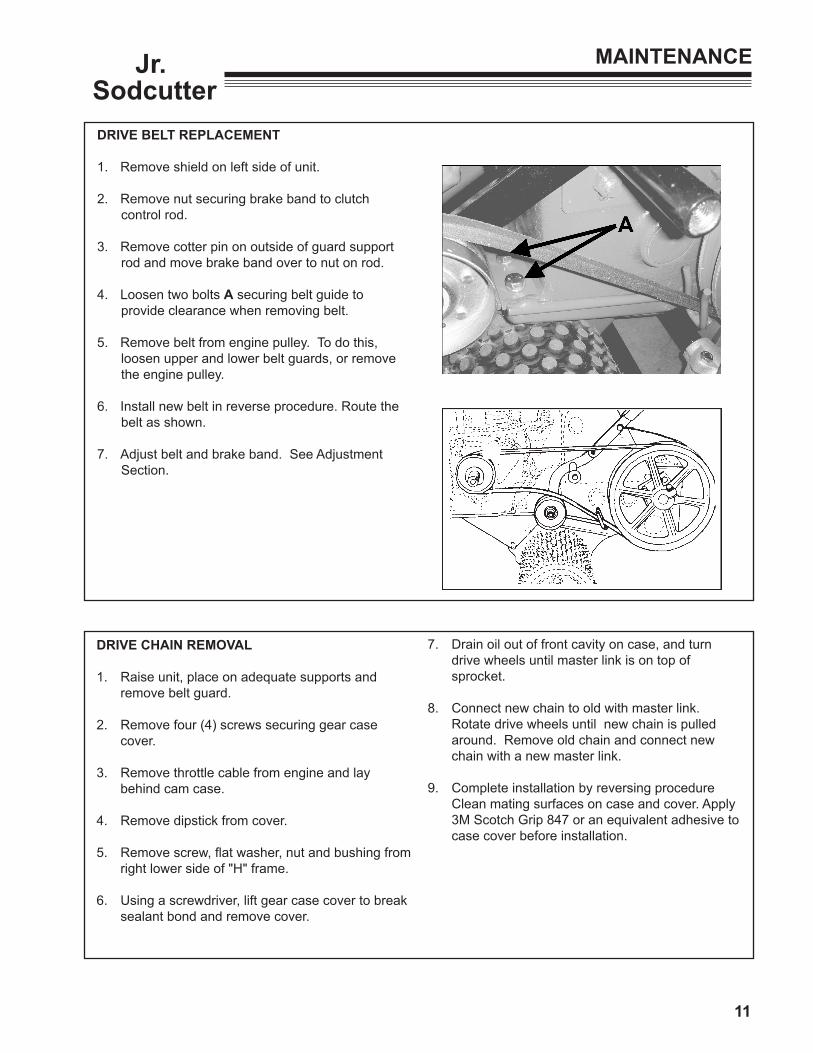
DRIvE BELT REPLACEMENT
1. Remove shield on left side of unit.
2. Remove nut securing brake band to clutch control rod.
3. Remove cotter pin on outside of guard support rod and move brake band over to nut on rod.
4. Loosen two bolts A securing belt guide to provide clearance when removing belt.
5. Remove belt from engine pulley. To do this, loosen upper and lower belt guards, or remove the engine pulley.
6. Install new belt in reverse procedure. Route the belt as shown.
7. Adjust belt and brake band. See Adjustment Section.
DRIvE CHAIN REMOvAL
1. Raise unit, place on adequate supports and remove belt guard.
2. Remove four (4) screws securing gear case cover.
3. Remove throttle cable from engine and lay behind cam case.
4. Remove dipstick from cover.
5. Remove screw, flat washer, nut and bushing from right lower side of "H" frame.
6. Using a screwdriver, lift gear case cover to break sealant bond and remove cover.
7. Drain oil out of front cavity on case, and turn drive wheels until master link is on top of sprocket.
8. Connect new chain to old with master link. Rotate drive wheels until new chain is pulled around. Remove old chain and connect new chain with a new master link.
9. Complete installation by reversing procedure Clean mating surfaces on case and cover. Apply 3M Scotch Grip 847 or an equivalent adhesive to case cover before installation.

12
Jr.Sodcutter
MAINTENANCE
DRIvE WHEEL CHAIN SPROCKET SHAFT
1. Follow steps 1 thru 7 in drive chain removal section.
2. Remove master link and remove chain from top sprocket.
3. Remove both drive wheels and axle keys.
4. Remove seal in case and snap ring retaining bearing in case.
5. Install axle nut on end of shaft, opposite the side of snap ring previously removed.
6. Using a soft hammer (lead, brass, etc.), drive shaft out of case. Sprocket can now be removed by lifting up on chain.
7. Top sprocket and chain should be checked for wear and replaced if necessary.
8. Reassemble in reverse procedure using new seals and gaskets.
BRAKE BAND REPLACEMENT AND ADJUSTMENT
1. Remove belt guard.
2. Remove old brake band. Retain all hardware.
3. Install new brake band with the large loop and hardware at the lower mounting point (on guard support rod).
4. Loosen the lock nut and the adjustment screw on the new brake band. Engage the Clutch Control lever and tighten the adjustment screw until the brake band is pulled snug against the belt. (See Brake Band Adjustment, pg. 5) Tighten the lock nut on brake adjustment screw. Make a test run. Stop engine and re-adjust brake band if necessary.
5. Re-install belt guard using original hardware.
NOTE: Make sure that cotter pin does not interfere with drive belt.
Routine brake band adjustment is necessary as the band and belt wear.
If brake band is not correctly attached to clutch control link, idler arm will rotate backward away from belt and no drive will occur.
Brake Band Lock Nut
Adjusting ScrewGuard Support Rod

13
Jr. Sodcutter
MAINTENANCE
BLADE DRIvE CHAIN REPLACEMENT
NOTE: To prevent small components from falling down into oil cavities and causing damage to unit, cover opening with clean rags, cardboard, etc.
1. Follow steps 1 thru 6 in drive chain removal section.
2. Remove bottom screw on bearing cage to drain
oil from rear cavity.
3. Rotate pulley shaft until master link is to front of top sprocket. Remove master link.
4. Rotate blade drive shaft until chain is free.
5. Install new chain in reverse procedure. Use 3M Scotch Grip 847 or an equivalent adhesive on case cover and bearing retainer screw.
UPPER DRIvE SPROCKET & SHAFT
1. Follow steps 1 thru 6 in drive chain removal section.
2. Remove master link from chain. Chain does not need to be removed from lower sprocket.
3. Remove drive shifter assembly from gear case.
4. Remove blade and side arms from pivot brackets for easier access.
5. Remove plugs on both ends of shaft.
6. Remove snap rings B from left bearing.
7. Using a punch and soft hammer (lead, leather, etc.), drive shaft out left side of unit and remove large gear.
8. Using a bearing puller or slide hammer, remove bearing. Shaft is now removable through cam case cover opening.
9. Dog clutch half is removable from gear by removing snap ring.
10. Assemble in reverse procedure.
11. After installing blade shifter assembly, adjust dog clutch to provide .015" (0.39 mm) clearance between clutch faces, as shown.
12. Apply 3M Scotch Grip adhesive or an equivalent to gear case cover before installation.
.015(0.39 mm)

14
Jr.Sodcutter
PULLEY SHAFT
1. Follow steps 1 thru 4 in belt replacement section and steps 2 thru 6 in drive chain removal section.
2. Remove blade from unit and remove left side arm.
3. Remove blade shifter assembly.
4. Turn pulley until master link is on top of sprocket. Remove chain from top sprocket.
5. Remove belt pulley and key.
6. Remove four (4) bearing cage screws and pull gears out left side of unit. Dog clutch and double sprocket will slide off as shaft is removed.
7. To remove gear and bearing, remove snap ring, slide gear off shaft and remove key. Remove bearing snap ring and remove bearing.
8. Assemble in reverse procedure. After blade shifter assembly is installed, adjust dog clutch to provide .015" (0.39 mm) clearance between clutch faces, as shown.
9. Apply 3M Scotch Grip 847 adhesive or equivalent to gear case cover before installation.
MAINTENANCE
.015(0.39 mm)

15
Jr. Sodcutter
BLADE SPROCKET SHAFT
1. Follow steps 1 thru 6 in pulley shaft section.
2. Loosen clamp screw on left pitman arm C and remove from shaft.
3. Loosen clamp screw in eccentric assembly D and remove.
4. Remove two (2) top screws securing the other side arm assembly. Side arm, shaft and pitman arm, are now removable by pulling side arm out.
5. Remove eccentric and both bearing cages E. Put a pan under rear portion of case to catch oil from case cavity.
6. Push shaft to left of case, lift right end of shaft out of case with bearings and sprocket intact.
7. To remove sprocket, press bearing from shaft, and slide sprocket off.
8. Assemble in reverse procedure. After blade shifter assembly is installed, adjust dog clutch to provide .015" (0.39 mm) clearance between clutch faces, as shown.
NOTE: End play on shaft must not exceed .005 (.127 mm) clearance and should rotate freely when bearing cages are tightened. Shim as required to obtain correct clearance.
9. Apply 3M Scotch Grip 847 adhesive or equivalent to gear case cover before installation.
MAINTENANCE
.015(0.39 mm)

16
Jr.Sodcutter
IDLER GEAR SHAFT
1. Remove belt guards.
2. Follow steps 2 thru 6 in drive chain removal section.
3. Remove plug from right side of unit.
4. Remove snap ring C from groove by small gear B to left end of shaft A.
5. Move small gear B to left side (from operators position) of case.
6. Move shaft A out right side of case until large gear clears shaft for removal.
7. Remove key from shaft and slide snap rings C off end of shaft.
8. Small gear B will slide off as shaft is removed from gear case.
MAINTENANCE / STORAGE
9. Assemble in reverse procedure. Apply 3M Scotch Grip 847 adhesive or equivalent to gear case cover before installation.
STORAGE INSTRUCTIONS
To prevent possible explosion or ignition of
vaporized fuel, do not store equipment with fuel in tank or carburetor in enclosure with open flame (for example, a furnace or water heater pilot light).
Daily Storage
1. Check engine oil level and air filter element daily.2. Check oil level in gear case.3. Close fuel valve at bottom of fuel tank.4. Clean cutting blade (grass, dirt, etc.).
EXTENDED STORAGE
Before the equipment is put into storage for any period exceeding 30 days:
1. Drain all fuel from fuel tank and lines (use a hose or fuel line, routed from fuel tank shut-off to proper container).
2. Start engine and run until all fuel is used from the carburetor float bowl.
3. While engine is warm, drain the crankcase oil and refill with the proper weight of oil corresponding to the season when the equipment will next be used.
4. Remove the spark plug and squirt a small quantity of engine oil into the cylinder. Turn the engine over a few times to distribute the oil.
5. Lubricate all lubrication fittings.6. Clean and oil cutting blade to prevent rust.
To put equipment into operation after an extended storage:
1. Fill fuel tank with clean fresh fuel.2. Check crankcase oil level, and start engine.3. Check fuel system for fuel leaks.

17
Jr. Sodcutter
TROUBLE SHOOTING
ELBISSOPMELBORP
ELBABORPESUAC YDEMER
niyatstonlliwedalB.dnuorg
.ffodednuorsiedalbfomottoB.A
.tesylreporptonsielgnaedalB.B
.A
.31egapeeS.elgnaedalbtsujdA.B
nogninnipriahtooRfomottobroedis
.edalb
asihtekamliosdnafrutfosepytemoS.A.melborp
dnaprahsartxeedalbehtpeeK.A.elgnawolatakcabdnuorg
.ffospmujtleB
.noitcurtsnoctlebfoepytgnorW.A
sirenethgittlebnehwkcalshcumooT.B.degagnesid
yrotcafnayRlaicepsehtylnoesU.A.tleb
dnadrawrofenigneedilS.B.dorlortnoctsujdaer
tonsrevelgnikcoLotdellupnehwthgit
.levartfotimil
.tungnikcolnoraewdaerhT.A
.detsujdaylreporptontungnikcoL.B
.tungnikcolecalpeR.A
etisopponotungnikcolnethgiT.B.doreitfodne
syellupnisbargtleBnehwspeerctinudna.degagnetonsihctulc
epytehttonsiro,deyarfdnadlositleB.A.tinuehthtiwtuotnes
.sevoorgyellupnitniaprotsuR.B
.drawrofrafoottesenignE.C
htiwecalpeR.Adengised,tleb
noitcurtsnocyrotcaf
.sehctulcrenethgittlebrof
.syelluphsilopdnanaelC.B.kcabenigneevoM.C
egagnetonseodreldIrevelhctulcnehwtleb
.drawrofdevomsi
roknilhctulcotdehcattatonsidnabekarB.A.nekorbsi
ekarbfodnereppuhcattaeR.Aekarbecalperroknilhctulcotdnab
.dnab
Sharpen or replace blade.See page 15.
18
Jr.Sodcutter
SPECIFICATIONS
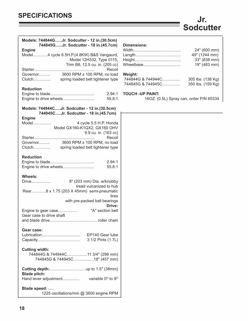
Models: 744844G......Jr. Sodcutter - 12 in.(30.5cm) 744845G......Jr. Sodcutter - 18 in.(45.7cm)EngineModel.............4 cycle 6.5H.P.(4.8KW) B&S Vangaurd,
Model 12H332, Type 0115,Trim B8, 12.5 cu. in. (205 cc)
Starter...................................................... RecoilGovernor.......... 3600 RPM ± 100 RPM, no loadClutch............... spring loaded belt tightener type
ReductionEngine to blade....................................... 2.94:1Engine to drive wheels............................ 55.8:1
Models: 744944C.....Jr. Sodcutter - 12 in.(30.5cm) 744945C.....Jr. Sodcutter - 18 in.(45.7cm)EngineModel................ 4 cycle 5.5 H.P. Honda
Model GX160-K1QX2, GX160 OHV9.9 cu. in. (163 cc)
Starter...................................................... RecoilGovernor.......... 3600 RPM ± 100 RPM, no loadClutch............... spring loaded belt tightener type
ReductionEngine to blade....................................... 2.94:1Engine to drive wheels............................ 55.8:1
Wheels:Drive................. 8" (203 mm) Dia. w/knobby tread vulcanized to hubRear.............8 x 1.75 (203 X 45mm) semi-pneumatic
tires with pre-packed ball bearings
Drive:Engine to gear case................. "A" section beltGear case to drive shaft and blade drive...........................................roller chain
Gear case:Lubrication.................................. EP140 Gear lubeCapacity...................................... 3 1/2 Pints (1.7L)
Cutting width:744844G & 744944C..................11 3/4" (298 mm)
744845G & 744945C..................18" (457 mm)
Cutting depth:................................up to 1.5" (38mm)Blade pitch:Hand lever adjustment............... variable 0O to 9O
Blade speed: .....1225 oscillations/min @ 3600 engine RPM
Dimensions:Width.......................................... 24" (600 mm)Length........................................ 49" (1244 mm)Height......................................... 33" (838 mm)Wheelbase................................. 19" (483 mm)
Weight: 744844G & 744944C................ 305 lbs. (138 Kg) 744845G & 744945C................ 350 lbs. (159 Kg)
TOUCH -UP PAINT: 16OZ. (0.5L) Spray can, order P/N 65334

19
JR SODCUTTERPARTS SECTION
PARTS SECTION
20
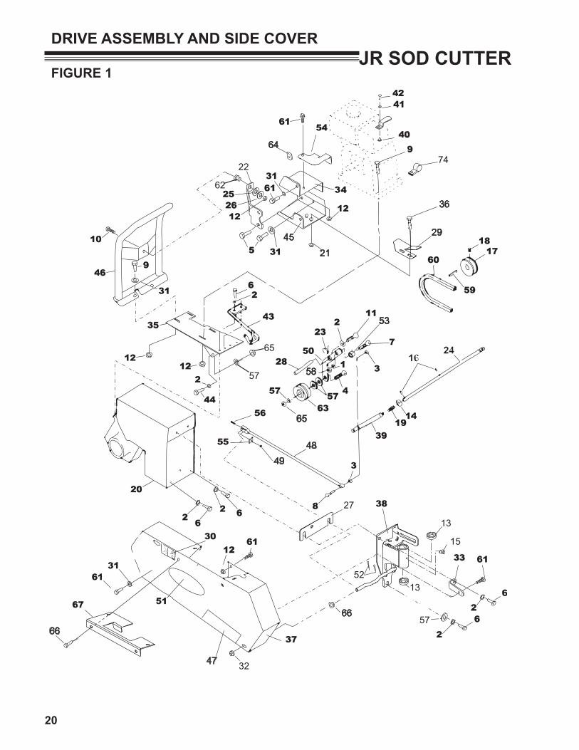
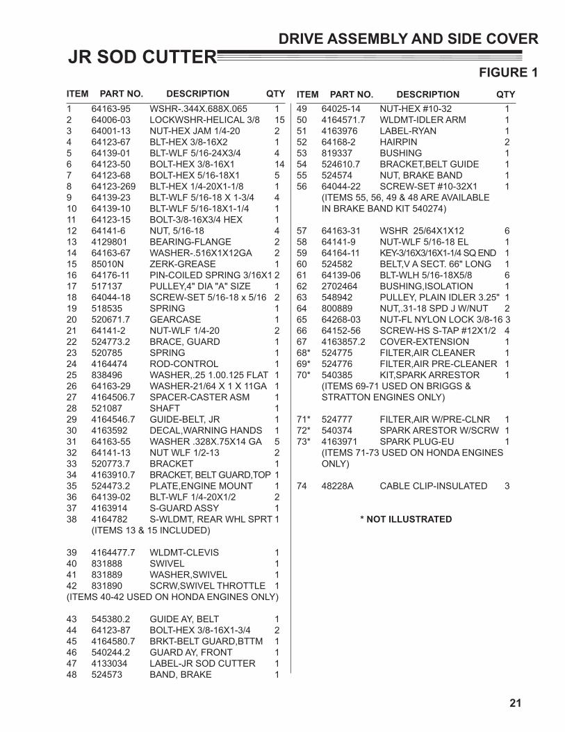
JR SOD CUTTERFIGURE 1
DRIvE ASSEMBLY AND SIDE COvER
45
47
22
32
52
27
21
36
29
15
13
13
4849
53
58
64
65
66
6657
62
57
65
74
21
ITEM PART NO. DESCRIPTION QTY ITEM PART NO. DESCRIPTION QTY
JR SOD CUTTERFIGURE 1
DRIvE ASSEMBLY AND SIDE COvER
1 64163-95 WSHR-.344X.688X.065 12 64006-03 LOCKWSHR-HELICAL 3/8 153 64001-13 NUT-HEX JAM 1/4-20 24 64123-67 BLT-HEX 3/8-16X2 15 64139-01 BLT-WLF 5/16-24X3/4 46 64123-50 BOLT-HEX 3/8-16X1 147 64123-68 BOLT-HEX 5/16-18X1 58 64123-269 BLT-HEX 1/4-20X1-1/8 19 64139-23 BLT-WLF 5/16-18 X 1-3/4 410 64139-10 BLT-WLF 5/16-18X1-1/4 111 64123-15 BOLT-3/8-16X3/4 HEX 112 64141-6 NUT, 5/16-18 413 4129801 BEARING-FLANGE 214 64163-67 WASHER-.516X1X12GA 215 85010N ZERK-GREASE 116 64176-11 PIN-COILED SPRING 3/16X1 217 517137 PULLEY,4" DIA "A" SIZE 118 64044-18 SCREW-SET 5/16-18 x 5/16 219 518535 SPRING 120 520671.7 GEARCASE 121 64141-2 NUT-WLF 1/4-20 222 524773.2 BRACE, GUARD 123 520785 SPRING 124 4164474 ROD-CONTROL 125 838496 WASHER,.25 1.00.125 FLAT 126 64163-29 WASHER-21/64 X 1 X 11GA 127 4164506.7 SPACER-CASTER ASM 128 521087 SHAFT 129 4164546.7 GUIDE-BELT, JR 130 4163592 DECAL,WARNING HANDS 131 64163-55 WASHER .328X.75X14 GA 532 64141-13 NUT WLF 1/2-13 233 520773.7 BRACKET 134 4163910.7 BRACKET, BELT GUARD,TOP 135 524473.2 PLATE,ENGINE MOUNT 136 64139-02 BLT-WLF 1/4-20X1/2 237 4163914 S-GUARD ASSY 138 4164782 S-WLDMT, REAR WHL SPRT 1 (ITEMS 13 & 15 INCLUDED)
39 4164477.7 WLDMT-CLEVIS 140 831888 SWIVEL 141 831889 WASHER,SWIVEL 142 831890 SCRW,SWIVEL THROTTLE 1(ITEMS 40-42 USED ON HONDA ENGINES ONLY)
43 545380.2 GUIDE AY, BELT 144 64123-87 BOLT-HEX 3/8-16X1-3/4 245 4164580.7 BRKT-BELT GUARD,BTTM 146 540244.2 GUARD AY, FRONT 147 4133034 LABEL-JR SOD CUTTER 148 524573 BAND, BRAKE 1
49 64025-14 NUT-HEX #10-32 150 4164571.7 WLDMT-IDLER ARM 151 4163976 LABEL-RYAN 152 64168-2 HAIRPIN 2 53 819337 BUSHING 1 54 524610.7 BRACKET,BELT GUIDE 155 524574 NUT, BRAKE BAND 156 64044-22 SCREW-SET #10-32X1 1 (ITEMS 55, 56, 49 & 48 ARE AVAILABLE IN BRAKE BAND KIT 540274)
57 64163-31 WSHR 25/64X1X12 658 64141-9 NUT-WLF 5/16-18 EL 159 64164-11 KEY-3/16X3/16X1-1/4 SQ END 160 524582 BELT,V A SECT. 66" LONG 161 64139-06 BLT-WLH 5/16-18X5/8 662 2702464 BUSHING,ISOLATION 163 548942 PULLEY, PLAIN IDLER 3.25" 164 800889 NUT,.31-18 SPD J W/NUT 265 64268-03 NUT-FL NYLON LOCK 3/8-16 366 64152-56 SCREW-HS S-TAP #12X1/2 467 4163857.2 COVER-EXTENSION 168* 524775 FILTER,AIR CLEANER 169* 524776 FILTER,AIR PRE-CLEANER 170* 540385 KIT,SPARK ARRESTOR 1 (ITEMS 69-71 USED ON BRIGGS & STRATTON ENGINES ONLY)
71* 524777 FILTER,AIR W/PRE-CLNR 172* 540374 SPARK ARESTOR W/SCRW 173* 4163971 SPARK PLUG-EU 1 (ITEMS 71-73 USED ON HONDA ENGINES ONLY)
74 48228A CABLE CLIP-INSULATED 3
* NOT ILLUSTRATED

22
JR SOD CUTTERFIGURE 2
MUFFLER GUARDS
12
2
34
5
6
6
4
7
3
HONDA MUFFLER GUARD
BRIGGS & STRATTION MUFFLER GUARD
89

23
ITEM PART NO. DESCRIPTION QTY ITEM PART NO. DESCRIPTION QTY
JR SOD CUTTERFIGURE 2
MUFFLER GUARDS
1 4160486.7 GUARD-MUFFLER B&S 1(USED ON B&S MODELS ONLY)
2 64152-56 SCREW-HS STAP #12X1/2 43 64205-038 BLT-METRIC M6-1.00X20 44 64006-01 LOCKWSHR-1/4 HELICAL 45 4160484.7 BRKT-MUFFLER GRD VERT 1
(USED ON B&S MODELS ONLY)
6 64163-02 WSHR .321/.328X.608X11GA 127 4160485.7 BRKT-MUFFLER GRD HORZ 1
(USED ON B&S MODELS ONLY)
8 4163902.7 GUARD-MUFFLER HONDA 1(USED ON HONDA MODELS ONLY)
9 64207-08 NUT-HEX M5-.8 EDGE LOCK 310* 4163904 KIT-MUFFLER, HONDA (CONTAINS ALL THE HONDA PARTS NEEDED TO
MOUNT ITEM 8)

24
JR SOD CUTTERFIGURE 3
GEAR CASE
23
356
816
1534
2453
54
51
49
46
5
25
44
4750
58
58
50
12
55
14
55
135058
41
3
816
15
5657
22
10
59
9
59
60
6
42
43
67
62
6364
65
66
68
7374
69
70
7064
71
71
72
72
45
171819
171819
171819
2 1
11
74
2131 32
30
61
2633
25
2927
28
50
58
48
20
52
3536
4037
39
38
5
40
3536
4 7
52

25
ITEM PART NO. DESCRIPTION QTY ITEM PART NO. DESCRIPTION QTY
JR SOD CUTTERFIGURE 3
GEAR CASE
1 64006-03 WSHR, 3/8 HELICAL LOCK 12 64123-67 BLT-HEX 3/8-16X2 13 64123-80 BLT-HEX 1/4-20X1-1/4 24 64006-02 LCKWSHER-HELICAL 5/16 125 64164-19 KEY WOODRUFF.19X.75 #9 36 64006-01 LOCKWASHER-1/4 HELICAL 47 64123-68 BOLT-HEX 5/16-18X1 128 515891 SHIM,.64 1.25.010 YS 49 515896.7 HANDLE-WHEEL SHIFTER 110 515897.7 HANDLE-BLADE SHIFTER 111 515901.7 PULLEY 112 516145 GEAR 113 516150 GEAR 114 516156 SHAFT 115 516194 SPRING 216 516196 SPRING 217 520238 SHIM .005 (.13MM) A/R18 520239 SHIM .010 (.25MM) A/R19 520240 SHIM .020 (.51MM) A/R20 520671.7 GEARCASE 121 521941 SPACER,1.00 1.12.66 122 524485 DECAL, BLADE SHIFTER 123 524486 DECAL, WHEEL SHIFTER 124 548931 PLUG,EXPANSION 1.75 YS 125 64164-28 KEY-#808 WOODRUFF 426 4139758 GEAR 127 516162 SPROCKET, CLUTCH 128 516172 CLUTCH 129 516173 SHAFT 130 544215 CAGE ASSY,BEARING 1 (INCLUDES ITEMS 31, 32)
31 548131 BRG,BALL 1.00 2.00.50 "DA" 132 548326 RING,INT RET 2.21OD.06 133 548327 RING-LOCK 134 544217.7 SHIFTER AY 135 545050 CAGE AY,BEARING 1 (INCLUDES ITEM 36)
36 814474 CUP,TPRD RLR BRG 137 516160 SPROCKET 138 521253 SHAFT-ECCENTRIC 139 548336 LOCK RING (KC) 140 814473 CONE,TPRD RLR BRG 1.00 241 545710 SHAFT AY 142 546033.7 DIPSTICK AY 1
43 546037.7 COVER AY, GEAR CASE 144 519404 GEAR,DRIVE 1 (INCLUDES ITEMS 45-47)
45 548775 PLUG.25-18NPTF HS 146 516222 HUB 147 548329 RING,EXT LOCK 1.61ID.06T 148 546937 CHAIN, #50 DOUBLE 149 547427 SPROCKET & SHAFT AY 150 548080 BRG.NDL.75 1.00.75 451 548096 BRG,BALL.59 1.38.43 "SS" 152 548272 SEAL,OIL 1.00 SHAFT 253 548321 RING,EXT RET.56ID.037 154 548323 RING, INTRNL RETAINING 255 548324 RING,EXT RET.691ID 256 548477 WASHER 457 548478 WSHR,.641 1.188.04 YS FLT 558 548482 PLUG,EXPANSION 1.25 YS 459 548597 LOCKNUT, UNI-TORQUE 260 548726 SCRW,.25-20.75 YS RS 461 4139759 SPACER-GEAR 1 62 307665 NUT .75-16 YS HX JAM 263 309799 LWSHR .75 ZS SHKPRF 264 520722 SPACER 265 520723 SHAFT 266 545626 SPROCKET AY 167 547398 CHAIN AY #50 RLR 168 547408.7 WHEEL AY 12IN 2 (USED ON 744844G & 744944C ONLY) 547424.7 WHEEL AY 18IN (USED ON 744845G & 744945C ONLY)69 64164-10 KEY 1/4X1-1/4 SQ 270 548952 RING INTERNAL RETAINING 271 548853 BRG-BALL 1.38 2.83.67 272 548954 SEAL-OIL 1.38 SHAFT 273 548480 LINK-HALF A/R74 4117675 LINK-#50 CONNECTOR A/R

26
JR SOD CUTTERFIGURE 4
SIDE ARMS, PITMAN ARMS AND HANDLES
27
45
45
45
45
4523
2
24
25
36
32 34
8
8
8
54
4735
5051
11
52
1053
13
47
33
13
37
1 42
5637
7
44
30
6
3
30
9
5
46
38
4841
39
141516
17
28 20
4331
29
40
26
2119
18
1822
55
49

27
ITEM PART NO. DESCRIPTION QTY ITEM PART NO. DESCRIPTION QTY
JR SOD CUTTERFIGURE 4
SIDE ARMS, PITMAN ARMS AND HANDLES
1 64123-50 BOLT-HEX 3/8-16X1 22 64123-107 BOLT-HEX 5/16-18X7/8 43 64123-61 BLT-HEX 5/16-18X1-3/4 24 328018 SCRW,.44-14 1.12 YS HX 65 515011 SCRW,.31-24 1.00 ZS HX 66 515729 BUSHING 27 516067 BUSH,STL.515X.874X1.015 28 4135868 COVER,HANDLE 39 521435.7 SHAFT, LOWER 110 4164446 PLATE-ADJUSTMENT STOP 111 4114727 KNOB-SPEED CONTROL 112 4164484 LABEL-CUT DEPTH, JR SOD 113 4164384.2 BRACKET, PIVOT 214 4164681 S-ECCENTRIC ASSY 2 (INCLUDES ITEMS 15 & 16)
15 521424 RING 116 548814 RACE, INNER 117 545437 ARM AY 2 (INCLUDES ITEMS 18-22)
18 64197-025 BLT-TDFM 1/4-20X5/8 219 521425.2 PLATE - COVER 120 521427 ARM, PITMAN 121 521428 BRG,NDL 1.25 1.62 1.06 122 85010-03 FITTING (KC) 123 4163915 BRACKET AY 2 (INCLUDES ITEMS 24, 25
24 521429 BRONZE BEARING 125 85010N ZERK-GREASE 126 4163915 ARM AY, SIDE 2 (INCLUDES ITEMS 27-31, 49)
27 521436 BALL BEARING 128 521438 GREASE SEAL 129 548138 BRG,NDL.88 1.12 1.00 230 548340 LOCK RING (KC) 231 35027N FTG, GREASE 90Dg. 132 4164541.2 WLDMT-LEVER 133 4164682 S-H-FRAME W/DECAL 1 (INCLUDES ITEM 55)
34 545449.2 HANDLE AY 135 524549 ROD,TIE LOWER 136 524550 ROD,TIE UPPER 137 64151-7 LOCKNUT, 1/2-13 HEX 238 64025-03 NUT-HEX 5/16-24 639 64006-16 LOCKWSHR-5/16 HI-COLLAR 240 64151-27 NUT-HEX 1/2-20 EDGE LOCK 241 800513 SCRW-SCKT 5/16-18-1-1/4 242 548056 NUT,.44-14 YS HX UNITORQ 643 64268-02 NUT-FL NYLN LCK 5/16-18 244 64268-03 NUT-FL NYLN LCK 3/8-16 545 64163-99 WSHR-.510X1.31X.179 646 64006-02 LOCKWSHR-HELICAL 5/16 647 4113281 WASHER, SPCL .531 SQ 248 4132717.7 BLADE-SOD CUTTER, 18" 149 4163589 LABEL-CHF VERT 2 50 2308066 WASHER-FIBER 151 64163-31 WSHR-15-64X1X12GA 152 64018-7 BLT-CRG 3/8-16X1/1/4 153 64268-03 NUT-FL NYLON 3/8-16 154 4164570.2 WLDMT-HANDLE 155 4164484 LABEL-CUT DEPTH 156 64141-9 BLT-WLF 5/16-18 CL 4

28
JR SOD CUTTERFIGURE 5
HANDLEBAR ASSEMBLY
39
52
13
40
2343
2
6
69
10
70
10
72
5245 21
31
27 61
52
1336
19
44
4
12
18
33
1720
48
11
34
41
38
14
22
42
16
5
51
75
15
9
1
71
24
4656
70
2949
26
25
3
58
57
59
60
61
6361
35
4746
64
62
66
6554
35
53
6665
6778
66
16
81 74 80
28
76
55
77 8283
8437 85
37
7380
13
5
32
68
3050
8
13
79
15
16

29
ITEM PART NO. DESCRIPTION QTY ITEM PART NO. DESCRIPTION QTY
JR SOD CUTTERFIGURE 5
HANDLEBAR ASSEMBLY
1 111898 CLAMP,CABLE 12 64025-15 NUT-HEX #10-24 KEPS 13 4161125 LABEL-RYAN 14 64025-04 NUT-WLF 3/8-16 15 64141-4 LCKWSHER-HELICAL 5/16 86 64197-015 BLT-TDFM 10-32X1/2 TORX 27 64262-006 BLT-FLG HD 5/16-18 X 3/4 48 64197-023 BLT-TDFM 10-32 X 3/4 1(USED FOR BRIGGS THROTTLE CABLE CLAMP)
9 64123-266 BLT-HEX 3/8-16X7 210 64197-025 BLT-TDFM 1/4-20X5/8 411 64140-1 COTTER PIN-1/8X1 112 64006-03 WSHR, 3/8 HELICAL LOCK 113 64163-03 WSHR-.256IDX62ODX18GA. 814 4164473.2 PLATE-BOLT CENTERING 215 64123-50 BLT-HEX 3/8-16X1 616 64268-03 NUT-FL NYLON LOCK 3/8-16 717 516544 BUSHING (PLATING) 118 64188-64 PIN-CLEVIS 3/8 X 1.75 119 4164519.7 FLAT-SWITCH ACTIVATION 120 522585.7 HANDLE,CONTROL 121 522727 GRIP,HANDLE 222 4164514 ISOLATOR-3/4X2 W/2 STUDS 423 524472 ARM, PIVOT (PLATING) 124 4164684 S-CONTROL PANEL EU 125 4163587 LABEL-CONTROL PANEL 126 64152-18 SCR 8-32 X 3/8 S-TAP 227 4164418.7 WLDMT-HANDLE, JRSOD 128 4164579.7 WLDMT-YOKE 129 540326 CONTROL ASSY,THROTTLE 1 (USED ON HONDA MODELS ONLY)
30 540229 WIRE AY 1 (USED ON HONDA MODELS ONLY)
31 540232 CONTROL AY, KILL SWITCH 132 64163-07 WSHR 1-1/32X1-3/4X1/4 133 548171 KNOB 134 64141-6 NUT, 5/16-18 235 4128901 BSHNG-FLNGD SINTRD IRN 236 64189-20 BLT-HEX SOC 1/4-20X5/8 237 2722682 BEARING-9IN WHEEL 238 64123-270 BLT-HEX 3/8-24X2-1/4 139 805421 SPRING,EXTENSION 140 806800 SWITCH,STOP LIGHT 141 524577 BUSHING, .328X.63X.41 242 64151-18 NUT-CENTER LOCK 3/8-16 243 814585 BUSHING 144 64139-06 BOLT-WLH 5/16-18X5/8 245 800896 SCRW-SET 1/4-20X3/8 1
46 64163-84 WSHR-1.015 X 1.75 X.125 247 4164551 SPRING-COMP,1.06X1.28X1 148 64163-61 WSHR .81X.406X16GA 149 4163186-01 CONTROL, THROTTLE 38.5 1 (USED ON B & S MODELS ONLY)
50 4163183 HARNESS-JR SOD B&S 1 (USED ON B & S MODELS ONLY)
51 64152-46 SCREW-SLT HH 10-24X1/2 152 64229-01 NUT-NYLON 1/4-20 753 4164782 S-WLDMT,REAR WHL ASSY 1 (INCLUDES ITEMS 35 & 54)
54 85010N ZERK-1/4-28 SEKF THRD 155 4164454 ROD-CASTER LIMITER 156 64123-15 BLT-HEX 3/8-16X3/4 157 4164456 HANDLE-ROD SUPPORT 158 4164606 SPRING-COMP, .75x11.75 159 64176-11 ROLL PIN-3/16 X 1 160 64025-19 NUT-HEX 1/2-13 261 64163-67 WSHR-.516X1X12GA 362 4164779.7 BRKT-LOCKING, STRAIGHT 163 518438 BUSHING-STL .39X.5X.359 164 64163-31 WSHR-25/64X1X1/2 165 64123-07 BLT-HEX 1/4-20X1-1/2 266 64025-01 NUT-HEX 1/4-20 467 64018-7 BLT-CRG 3/8-16X1-1/4 168 4164627 SPRING-EXTENSION 169 4164475.7 BRKT-MOUNTING 170 64123-89 BLT-HEX 1/4-20X3/4 571 4129802 TUBE-DOCUMENT 172 38061A CAP-VINYL 173 2722681 ASY-9"WHEEL 1 (INCLUDES ITEMS 37,77, 81-85)
74 2022230-04 SPANNER 175 4164384.2 BRACKET, PIVOT 276 64229-05 LOCKNUT-NYLON 1/2-13 177 64141-1 NUT-WLF 5/16-24 478 64123-166 BLT-HEX 1/2-13 X 5-1/2 179 4164780.7 BRACKET-ADJUSTER 1 80 2722591 SPACER-3/4 BEARING 281 64123-01 BLT-HEX 5/16-24X3/4 482 2720645 S-WHL HALF, VALVE SD 183 38504 S-TIRE 9X3.5-4 SMOOTH 184 2720644 S-WHEEL HALF 185 2722680 HUB-9" WHEEL W/BRGS 1

30
JR SOD CUTTERFIGURE 6
MOLE BLADE KIT
6
51415
818 1
234
7
10
911
13
12
17
1619

31
ITEM PART NO. DESCRIPTION QTY ITEM PART NO. DESCRIPTION QTY
JR SOD CUTTERFIGURE 6
MOLE BLADE KIT
1 544670 MOLE BLADE KIT- 3/4" 1 (USED ON 744844G & 744944C) (INCLUDES ITEMS 14 & 16-17)
2 544725 MOLE BLADE KIT- 3/4" 1 (USED ON 744845G & 744945C) (INCLUDES ITEMS 13 & 15-17)
3 544673 MOLE BLADE KIT- 1-1/4" 1 (USED ON 744844G & 744944C) (INCLUDES ITEMS 7, 9-14 & 17-19)
4 544728 MOLE BLADE KIT- 1-1/4" 1 (USED ON 744845G & 744945C) (INCLUDES ITEMS 5-7, 9-13, 15, & 17-19)
5 64006-03 WSHR, 3/8 HELICAL LOCK 46 64025-04 NUT-3/8-24 HEX 47 64123-21 BLT-HEX 3/8-24X1-1/4 48 544689 BLADE AY, MOLE 3/4" 1 (INCLUDES ITEMS 9-13)
9 64025-02 NUT-HEX 5/16-18 110 316943 PIN,SPIROL.250.750 PS 111 515691 SWIVEL 112 547052 CHAIN AY 113 800513 SCREW-SCKT 5/16-18-1-1/4 114 546089 BRACKET,12"-MOLE BLADE 1 (USED ON 744844G & 744944C)
15 546092 BRACKET,18"-MOLE BLADE 1 (USED ON 744845G & 744945C)
16 548613 KELLEM GRIP 1 (USED ON 544670 & 544725)
17 808222 LINK,CHAIN CONN 118 544692 BLADE AY, MOLE 1-1/4" 1 (INCLUDES ITEMS 9-13)
19 548616 KELLEM GRIP 1 (USED ON KITS 544673 & 544728)

32
JR SOD CUTTERFIGURE 7
TRENCHING BLADE

33
ITEM PART NO. DESCRIPTION QTY ITEM PART NO. DESCRIPTION QTY
JR SOD CUTTERFIGURE 7
TRENCHING BLADE
1 546199 BLADE KIT 1 (INCLUDES ITEMS 2-6) * MODEL 744844G, ONLY
2 64006-03 WSHR, 3/8 HELICAL LOCK 33 64025-04 NUT-3/8-24 HEX 34 64123-21 BLT-HEX 3/8-24X1-1/4 35 546089 BRACKET,12"-MOLE BLADE 16 546198 BLADE AY,TRENCHING 1
*NOTE: The trenching blade set includes parts for installation on earlier model sodcutters. Discard any parts not required for installation on model 744844C and newer.

BOB-CAT BUNTON RYAN STEINER
SCHILLER GROUNDS CARE, INC.ONE BOB-CAT LANEP.O. BOX 469JOHNSON CREEK, WI 53038920-699-2000www.schillergc.com