self-priming chemical process pumps · 4 operating point has long been exceeded. the heating of the...
TRANSCRIPT
Dean Pump Division
Bulletin C 1.2.34.7
Self-Priming
Chemical Process Pumps
pHP Series

• Capacities to 700 GPM (160 m3/hr)
• Heads to 400 feet (120 m)
• Pumping temperatures to 500°F (260°C)
• Working pressures to 275 PSIG (1,896 kPa)
Principles of OperationA self-priming pump is one in which the impeller, operating in thepriming liquid, removes the air from the pump suction line. Thisresults in a vertical rise of the process fluid in the suction line froma source below the pump. Once sufficient air is thereby removed,the process fluid flows into the pump and the pump primes. Thevertical rise of the liquid is called “lift”. The removal of air from thesuction piping permits pressure, acting on the liquid surface of thesource tank, to push the process fluid up into the pump. Usually thesource is at atmospheric pressure, which provides a theoretical liftof 34 feet at sea level; however, the practical lift limit is 20 feet.
If the liquid in the source tank is at such an elevated temperaturethat vacuum pulled in the suction line causes the liquid to flash tovapor in the suction line, the pump cannot prime.
A self-priming pump requires liquid in the casing to achieve thepriming action. An initial prime is accomplished by filling thepump casing with liquid through the priming hole in the top of thecasing. The pump is then started and allowed to prime. The pumpmay be turned off and reprimed thereafter with the liquid retainedin the special pump casing.
The action inside the pump during priming is one of air entrain-ment and larger bubbles passing with the priming liquid throughthe upper volute educer passage. The air separates out of this liquid in the upper chamber of the casing. This liquid returns to theentry port in the lower volute section and is recycled back into theimpeller.
This action continues until sufficient air has been expelled to allowthe pump to prime. Once prime is established, the pump operatesjust like a standard centrifugal pump.
During the priming cycle, there must be no air leaks in the suctionpiping or the shaft sealing device. Leakage of air into the systemmay prevent the pump from achieving prime.
When the pump prime is broken, the liquid in the suction pipeflows back into the liquid suction source. There may be a siphoneffect, greater or lesser, depending on height, liquid and velocity.Although this pulls more liquid from the casing, there is always suf-ficient liquid retained in the pHP casing to start the priming cycleagain. Thus, repriming can occur.
A self-priming pump is not a cure for an NPSH problem. The NPSHrequired by the pump is necessary for the pump to continue oper-ating. A self-priming pump will handle occasional periods ofvapor or air and will recover, but the NPSH required by the pump
must be provided. This will depend upon the amount of lift requiredand the vapor pressure of the fluid being pumped.
Priming Time Calculation• Determine the effective suction lift. (Multiply vertical suction lift
by specific gravity).
• Refer to the priming time curves. Using the effective suction lift, enter the priming time curve, read across to the impeller diameter selected and down to the priming time.
This is the priming time if the suction line is the same size as thesuction flange and is all vertical lift without horizontal component.
To correct priming time for a different size of suction line and/orhorizontal piping, use the formula below:
tpc = corrected priming time in secondstp = priming time from curveL t = total length of suction pipe above the liquid surface in feetL v = vertical height from surface of liquid to centerline of pumpD = diameter of suction pipe, nominal, in inchesd = pump suction size, nominal, in inches
tpc = tp (L t/Lv) (D/d)2
EXAMPLEAssume:
Vertical lift (L v) = 20 feetTotal length of suction pipe (L t) = 40 feetPriming time (tp) = 42 secondsSuction line D = 4” nominal diameterSuction flange d = 3” nominal diameter
Then:tpc = 42 (40/20) (4/3)2 = 149.3 seconds
Heating of priming liquid can reduce the maximum lift, but usually the NPSH above the vapor pressure requirement for the
Dean Pump Series pHP Self-Priming Chemical Pumps
L v
2

TOTA
L HEA
D –
METE
RS 2
900
RPM
– 50
HER
TZ
25 50 75 100 125 150
100
80
60
40
20
500
400
300
200
100
0
CAPACITY – M3/HR 2900 RPM – 50 HERTZ
TOTA
L HEA
D –
FEET
350
0 RP
M –
60 H
ERTZ
CAPACITY – U.S. GPM 3500 RPM – 60 HERTZ
0 100 200 300 400 500 600 700 800 900
4X4X103X3X10
2X2X10
11/2X11/2X8
pHP Self Primer - 2 Pole 3500 RPM
pHP Self Primer - 4 Pole 1750 RPM
Maximum Allowable Working Pressure
HEAD CAPACITY RANGE CHARTS
TOTA
L HEA
D –
METE
RS 1
450
RPM
– 50
HER
TZ
25 50 75 100 125
35
30
25
20
15
10
5
180
160
140
120
100
80
60
40
20
CAPACITY – M3/HR 1450 RPM – 50 HERTZ
TOTA
L HEA
D –
FEET
175
0 RP
M –
60 H
ERTZ
CAPACITY – U.S. GPM 1750 RPM – 60 HERTZ
0 100 200 300 400 500 600 700
4X4X131/2
4X4X103X3X102X2X10
11/2X11/2X8
-100 0 100 200 300 400 500 600
PUMPING TEMPERATURE – °F
PUMPING TEMPERATURE – °C
WORK
ING
PRES
SURE
– P
SIG
WORK
ING
PRES
SURE
– K
Pa
300
250
200
150
100
50
0
Class 50 (316SS)
-50 0 50 100 150 200 250 300
2000
1800
1600
1400
1200
1000
800
600
400
200
0
Class 22 (Ductile Iron)
Minim
um Te
mper
atur
e Lim
it -2
0°F
pHP2110 & pHP2140
3
4
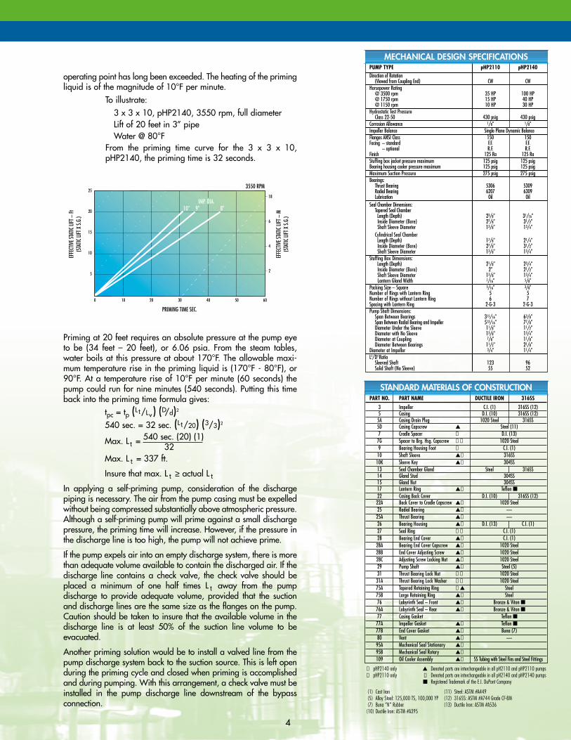
operating point has long been exceeded. The heating of the primingliquid is of the magnitude of 10°F per minute.
To illustrate: 3 x 3 x 10, pHP2140, 3550 rpm, full diameterLift of 20 feet in 3” pipeWater @ 80°F
From the priming time curve for the 3 x 3 x 10,pHP2140, the priming time is 32 seconds.
Priming at 20 feet requires an absolute pressure at the pump eyeto be (34 feet – 20 feet), or 6.06 psia. From the steam tables,water boils at this pressure at about 170°F. The allowable maxi-mum temperature rise in the priming liquid is (170°F - 80°F), or90°F. At a temperature rise of 10°F per minute (60 seconds) thepump could run for nine minutes (540 seconds). Putting this timeback into the priming time formula gives:
tpc = tp (L t/Lv) (D/d)2
540 sec. = 32 sec. (L t/20) (3/3)2
Max. L t = 540 sec. (20) (1)32
Max. L t = 337 ft.
Insure that max. L t ≥ actual L t
In applying a self-priming pump, consideration of the discharge piping is necessary. The air from the pump casing must be expelledwithout being compressed substantially above atmospheric pressure.Although a self-priming pump will prime against a small dischargepressure, the priming time will increase. However, if the pressure inthe discharge line is too high, the pump will not achieve prime.
If the pump expels air into an empty discharge system, there is morethan adequate volume available to contain the discharged air. If thedischarge line contains a check valve, the check valve should beplaced a minimum of one half times L t away from the pump discharge to provide adequate volume, provided that the suctionand discharge lines are the same size as the flanges on the pump.Caution should be taken to insure that the available volume in thedischarge line is at least 50% of the suction line volume to be evacuated.
Another priming solution would be to install a valved line from thepump discharge system back to the suction source. This is left openduring the priming cycle and closed when priming is accomplishedand during pumping. With this arrangement, a check valve must beinstalled in the pump discharge line downstream of the bypass connection.
PUMP TYPE pHP2110 pHP2140Direction of Rotation
(Viewed from Coupling End) CW CWHorsepower Rating
@ 3500 rpm 35 HP 100 HP@ 1750 rpm 15 HP 40 HP@ 1150 rpm 10 HP 30 HP
Hydrostatic Test PressureClass 22-50 430 psig 430 psig
Corrosion Allowance 1/8" 1/8"Impeller Balance Single Plane Dynamic BalanceFlanges ANSI Class 150 150Facing – standard F.F. F.F.
– optional R.F. R.F.Finish 125 Ra 125 RaStuffing box jacket pressure maximum 125 psig 125 psigBearing housing cooler pressure maximum 125 psig 125 psigMaximum Suction Pressure 275 psig 275 psigBearings:
Thrust Bearing 5306 5309Radial Bearing 6207 6309Lubrication Oil Oil
Seal Chamber Dimensions:Tapered Seal ChamberLength (Depth) 23/8" 31/16"Inside Diameter (Bore) 27/8" 31/2"Shaft Sleeve Diameter 13/8" 13/4"
Cylindrical Seal ChamberLength (Depth) 17/8" 21/4"Inside Diameter (Bore) 27/8" 31/2"Shaft Sleeve Diameter 13/8" 13/4"
Stuffing Box Dimensions:Length (Depth) 21/8" 23/4"Inside Diameter (Bore) 2" 21/2"Shaft Sleeve Diameter 13/8" 13/4"Lantern Gland Width 7/16" 5/8"
Packing Size – Square 5/16" 3/8"Number of Rings with Lantern Ring 5 5Number of Rings without Lantern Ring 6 7Spacing with Lantern Ring 2-G-3 2-G-3Pump Shaft Dimensions:
Span Between Bearings 315/16" 63/8"Span Between Radial Bearing and Impeller 513/16" 77/8"Diameter Under the Sleeve 11/8" 11/2"Diameter with No Sleeve 13/8" 13/4"Diameter at Coupling 7/8" 11/8"Diameter Between Bearings 11/2" 21/8"
Diameter at Impeller 3/4" 11/4"L3/D4 Ratio
Sleeved Shaft 123 96Solid Shaft (No Sleeve) 55 52
PART NO. PART NAME DUCTILE IRON 316SS
3 Impeller C.I. (1) 316SS (12)5 Casing D.I. (10) 316SS (12)
5A Casing Drain Plug 1020 Steel 316SS5D Casing Capscrew ▲ Steel (11)7 Cradle Spacer ① D.I. (13)
7G Spacer to Brg. Hsg. Capscrew ①✝ 1020 Steel9 Bearing Housing Foot ① C.I. (1)
10 Shaft Sleeve ▲✝ 316SS10K Sleeve Key ▲✝ 304SS13 Seal Chamber Gland Steel 316SS14 Gland Stud 304SS15 Gland Nut 304SS17 Lantern Ring ▲✝ Teflon ■22 Casing Back Cover D.I. (10) 316SS (12)
22A Back Cover to Cradle Capscrew ▲✝ 1020 Steel25 Radial Bearing ▲✝ —
25A Thrust Bearing ▲✝ —26 Bearing Housing ▲✝ D.I. (13) C.I. (1)27 Seal Ring ①✝ C.I. (1)28 Bearing End Cover ▲✝ C.I. (1)
28A Bearing End Cover Capscrew ▲✝ 1020 Steel28B End Cover Adjusting Screw ▲✝ 1020 Steel28C Adjusting Screw Locking Nut ▲✝ 1020 Steel29 Pump Shaft ▲✝ Steel (5)31 Thrust Bearing Lock Nut ①✝ 1020 Steel
31A Thrust Bearing Lock Washer ①✝ 1020 Steel75A Tapered Retaining Ring ②▲ Steel75B Large Retaining Ring ▲✝ Steel76 Labyrinth Seal – Front ▲✝ Bronze & Viton ■
76A Labyrinth Seal – Rear ▲✝ Bronze & Viton ■77 Casing Gasket Teflon ■
77A Impeller Gasket ▲✝ Teflon ■77B End Cover Gasket ▲✝ Buna (7)80 Vent ▲✝ —
95A Mechanical Seal Stationary ▲✝
95B Mechanical Seal Rotary ▲✝
109 Oil Cooler Assembly ▲✝ SS Tubing with Steel Fins and Steel Fittings
① pHP2140 only ▲ Denoted parts are interchangeable in all pH2110 and pHP2110 pumps② pHP2110 only ✝ Denoted parts are interchangeable in all pH2140 and pHP2140 pumps
■ Registered Trademark of the E.I. DuPont Company
(1) Cast Iron (11) Steel: ASTM #A449(5) Alloy Steel: 125,000 TS, 100,000 YP (12) 316SS: ASTM #A744 Grade CF-8M(7) Buna “N” Rubber (13) Ductile Iron: ASTM #A536
(10) Ductile Iron: ASTM #A395
STANDARD MATERIALS OF CONSTRUCTION
MECHANICAL DESIGN SPECIFICATIONS
EFFE
CTIV
E STA
TIC LI
FT –
M(S
TATIC
LIFT
X S.
G.)
18
6
4
2
25
20
15
10
5
3550 RPM
PRIMING TIME SEC.
0 10 20 30 40 50 60
EFFE
CTIV
E STA
TIC LI
FT –
Ft(S
TATIC
LIFT
X S.
G.)
10" 9" 8"IMP. DIA.

5
pHP2110
pHP2140
6040 Guion Road P.O. Box 68172 Indianapolis, IN 46268-0172Phone: (317) 293-2930 TOLL FREE: (800) 801-9265 FAX: (317) 297-7028E-Mail: [email protected] Web Site: www.deanpump.com
Dean Pump Division
© COPYRIGHT 2004 MET-PRO CORPORATION, DEAN PUMP DIVISION Dean Pump IS A REGISTERED TRADEMARK OF MET-PRO CORPORATION 09-5912 404
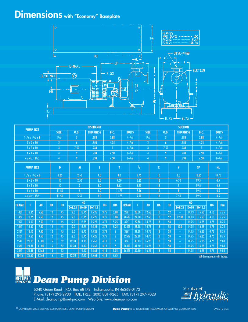
Dimensions with “Economy” Baseplate
PUMP SIZEDISCHARGE SUCTION
SIZE O.D. THICKNESS B.C. BOLTS SIZE O.D. THICKNESS B.C. BOLTS
11/2 x 11/2 x 8 11/2 5 .688 3.88 4–1/2 11/2 5 .688 3.88 4–1/2
2 x 2 x 10 2 6 .750 4.75 4–5/8 2 6 .750 4.75 4–5/8
3 x 3 x 10 3 7.50 .938 6 4–5/8 3 7.50 .938 6 4–5/8
4 x 4 x 10 4 9 .938 7.50 8–5/8 4 9 .938 7.50 8–5/8
4 x 4 x 131/2 4 9 .938 7.50 8–5/8 4 9 .938 7.50 8–5/8
PUMP SIZE D M S T T1 X Y CP HL
11/2 x 11/2 x 8 8.25 2.50 4.0 8.0 6.75 10 6.0 13.25 10.75
2 x 2 x 10 10 2.50 6.0 7.50 6.25 12 6.50 19.5 4.5
3 x 3 x 10 10 3 6.0 8.63 6.25 13 7 19.5 4.5
4 x 4 x 10 11.50 5 6.0 11.75 7.56 13 8 19.5 4.5
4 x 4 x 131/2 11.50 5.50 6.0 11.75 9.50 16 7.50 19.5 4.5
FRAME C AB HA HBHD
HG HMD=8.25 D=10 D=11.5
143T 13.25 6.50 12 45 12.0 13.75 15.25 3.75 3.88145T 13.75 6.50 12 45 12.0 13.75 15.25 3.75 3.88182T 14.63 7.50 12 45 12.0 13.75 15.25 3.75 5.25184T 15.63 7.50 12 45 12.0 13.75 15.25 3.75 5.25213T 18.13 9.50 12 45 12.0 13.75 15.25 3.75 6215T 19.63 9.50 12 45 12.0 13.75 15.25 3.75 6254T 23.13 11.00 15 52 12.38 14.13 15.63 4.13 7256T 24.88 11.00 15 52 12.38 14.13 15.63 4.13 7284T 26.88 12.63 15 52 – 14.13 15.63 4.13 7.75284TS 25.50 12.63 15 52 12.38 14.13 15.63 4.13 7.75
FRAME C AB HA HBHD
HG HMD=8.25 D=10 D=11.5
286T 28.38 12.63 15 52 – 14.13 15.63 4.13 7.75286TS 27.00 12.63 15 52 12.38 14.13 15.63 4.13 7.75324T 29.88 14.75 18 58 – 14.75 16.25 4.75 8.75324TS 28.38 14.75 18 58 13.0 14.75 16.25 4.75 8.75326T 31.38 14.75 18 58 – 14.75 16.25 4.75 8.75326TS 29.88 14.75 18 58 – 14.75 16.25 4.75 8.75364T 33.13 16.25 18 58 – 14.75 16.25 4.75 9.88364TS 31.50 16.25 18 58 – 14.75 16.25 4.75 9.88365TS 32.50 16.25 18 58 – 14.75 16.25 4.75 9.88
All dimensions are in inches.