self-lubricated bearing
TRANSCRIPT

United States Patent [19]
Woelki et al.
US005971617A
5,971,617 Oct. 26, 1999
Patent Number:
Date of Patent:
[11]
[45]
[54]
[75]
SELF-LUBRICATED BEARING
Inventors: Peter Woelki, Monchengladbach, Germany; Dominique Petit, Housse, Belgium; Friedrich Harig, Willich, Germany
Assignee: Norton Pampus GmbH, Willich, Germany
Appl. No.: 08/899,572
Filed: Jul. 24, 1997
Int. Cl.6 .................................................... .. F16C 17/02
US. Cl. ........................................... .. 384/295; 384/284
Field of Search .................................... .. 384/276—300
References Cited
U.S. PATENT DOCUMENTS
2,689,380 9/1954 Tait ........................................... .. 18/59
2,691,814 10/1954 Tait ..... .. 29/182.5
2,788,324 4/1957 Mitchell 252/12.2 2,798,005 7/1957 Love . . . . . . . . . . . . . . . . . . . . . . .. 117/8
2,813,041 11/1957 Mitchell et a1. . .. 117/21
2,995,462 8/1961 Mitchell et a1. . 117/8 3,234,128 2/1966 McLeish et a1. ........................ .. 252/12
5,573,846 11/1996 Harig et al. ........................... .. 428/323
Primary Examiner—Lenard A. Footland Attorney, Agent, or Firm—Mary E. Porter; Sampson & Associates
[57] ABSTRACT
A self-lubricating bearing is fabricated as a laminate of a metallic substrate and a series of raised structures formed integrally therewith and extending orthogonally therefrom. A ?uoropolymer sliding or bearing layer is superposed With the substrate, With the raised structures embedded therein. The raised structures serve to hold the bearing layer in place to help prevent it from sliding along the surface of substrate during bearing operation. This anchorage to the substrate enables a relatively thick bearing layer to be utilized to relatively reduce tendency to creep. Alternatively, the struc tures provide a bearing having a relatively thin load bearing layer With a relatively constant friction coefficient over its life, With the structures acting as thermal and electrical bridges for relatively high heat and electrical conductivity betWeen the substrate and a supported article such as a rotating shaft. The structures also may be in direct contact With the supported article to help prevent bedding-in. In this regard, the bearings are provided With a relatively low coefficient of friction, long bearing life, resistance to creep and mechanical stresses, and are electrically and thermally conductive.
25 Claims, 3 Drawing Sheets
U.S. Patent Oct.26, 1999 Sheet 1 of3 5,971,617
11
10
22 15
CREEP CREEP
18 20
1 FIG. PRIOR ART


U.S. Patent Oct.26, 1999 Sheet 3 of3 5,971,617
NHH QNH QNH vHH // a:

5,971,617 1
SELF-LUBRICATED BEARING
BACKGROUND OF THE INVENTION
1. Field of the Invention This invention relates to bearings, and more particularly
to a maintenance free bearing having a lubricious Wear layer that is resistant to creep.
2. Background Information Maintenance-free sliding bearings comprising a metal
support and a plastic layer are knoWn. Such bearings provide convenient means for rotatably, pivotably or slidably fas tening multiple members to one another in a maintenance free manner. Applications for such bearings include those that utiliZe continuous rotational movement such as journals for supporting a driven shaft. These bearings are also suitable for applications that employ repeated pivotal move ment such as automotive door hinges, door checks, brake and accelerator pedals. Additional applications include those that utiliZe repeated reciprocal movement such as automo tive shock absorbers and struts. These bearings may also be used in lighter duty applications such as multiple bar link ages commonly utiliZed in the automotive industry for trunk deck lid and hood hinges. Such maintenance free bearings may comprise a variety of con?gurations, such as, for example, bushes or journal bearings, thrust bearings or Washers, locating pads, valve port plates, and Wearing com ponents for a variety of mechanisms.
One such bearing in particular is referred to herein as a “DU” bearing available from The Glacier Metal Company Limited, Argule House, Joel Street, NorthWood Hills, Middlesex HA6 lLN, England. The DU bearing consists of a composite material in Which a porous bronZe layer is bonded to a metal backing. The porous bronZe layer is impregnated With a polymer such as PTFE (polytetra?uoroethylene), With a top layer or lining of poly mer disposed thereon.
One aspect of this construction is that the ratio of polymer to bronZe tends to change With depth, With the bronZe being relatively more concentrated closer to the metal backing. This provides a reduced concentration of loW friction mate rial close to the backing metal. Thus, the coef?cient of friction tends to disadvantageously vary (increase) over the bearing life. An additional draWback of this concentration gradient is that any operation that removes material from the bearing layer, such as the common practices of boring, broaching or burnishing the bearings to siZe after installation, generally cannot be accomplished Without a reduction in bearing performance. A bearing developed to overcome these limitations, sold
under the designation “Norglide”, is available from Norton Pampus, GmbH, of Willich, Germany. Norglide comprises a thin sheet of bearing material, such as, for example, a PTFE compound, bonded onto steel backing using high tempera ture thermoplastic ?lms, (eg. PFA and ETFE) heat and pressure. Since the bearing layer is fabricated as a discrete sheet, rather than a dispersion as in the case of the afore mentioned DU bearings, the Norglide bearing layer is homo geneous. This aspect advantageously provides a coef?cient of friction that remains nominally constant throughout the bearing life. Moreover, the coef?cient of friction of the Norglide bearing may be loWer than other prior art bearings due to the ability to utiliZe reduced ?ller content or ?llers that have less negative impact on the coef?cient of friction. For example, the Norglide bearing may utiliZe graphite ?ller rather than bronZe as discussed hereinabove. Also, such homogeneity enables the bearing surface of Norglide bear
15
25
35
45
55
65
2 ings to be bored, broached or burnished to siZe after instal lation nominally Without reducing the performance thereof.
This construction, hoWever, is not Without limitations. In particular, the relatively high thickness of the PTFE com pound and the loW ?ller content tend to enable the bearing layer to creep or bed in under heavy stress. Moreover, the bearing layer may tend to delaminate from the metal backing in the event the laminate is bent to a particularly small radius. PTFE compounds also tend to be poor conductors of heat. As such, these bearings, even When fabricated using bronZe ?lled PTFE sheets (see the discussion of “Norglide M” bearings hereinbeloW), tend to exhibit relatively loW heat transfer. Finally, although PTFE may be made electri cally conductive, the hot melt ?lm used to bond the bearing layer to the metal backing is electrically insulative. This aspect tends to make the Norglide bearings undesirable for use in applications that rely on electrical continuity such as, for example, electrostatic painting in the automotive and other metal fabricating industries. The creep and delamination problems may be addressed
by roughening the metal backing surface, such as by sandblasting, etc., prior to application of the bearing surface. HoWever, the process is relatively cumbersome, time con suming and adds expense to the process. As mentioned hereinabove, a variation of Norglide also
available from Norton Pampus is knoWn as “Norglide M.” Norglide M is substantially similar to Norglide, but utiliZes a bearing layer having an open-mesh metal fabric reinforce ment disposed therein. The use of this reinforcement tends to ameliorate the aforementioned creep and conductivity draWbacks, but does not address the delamination and elec trical conductivity concerns.
Thus, a need exists for an improved maintenance free bearing that addresses the problems of the prior art.
SUMMARY OF THE INVENTION
According to a ?rst aspect of the present invention, a maintenance-free sliding bearing includes a substrate having a surface and a plurality of structures disposed in spaced relation along, and extending substantially orthogonally therefrom. A load bearing layer is superposed With the surface in engagement With the plurality of structures, so that the structures are embedded therein.
In a second aspect of the present invention, a method of fabrication of a maintenance-free sliding bearing includes the steps of:
(a) providing a substrate having a surface; (b) integrally disposing a plurality of structures in spaced
relation along, and extending substantially orthogo nally from, the surface; and
(c) disposing a load bearing layer in superposed alignment With the surface in engagement With the plurality of structures, Wherein the structures are embedded into the load bearing layer.
The above and other features and advantages of this invention Will be more readily apparent from a reading of the folloWing detailed description of various aspects of the invention taken in conjunction With the accompanying draW ings.
BRIEF DESCRIPTION OF THE DRAWINGS
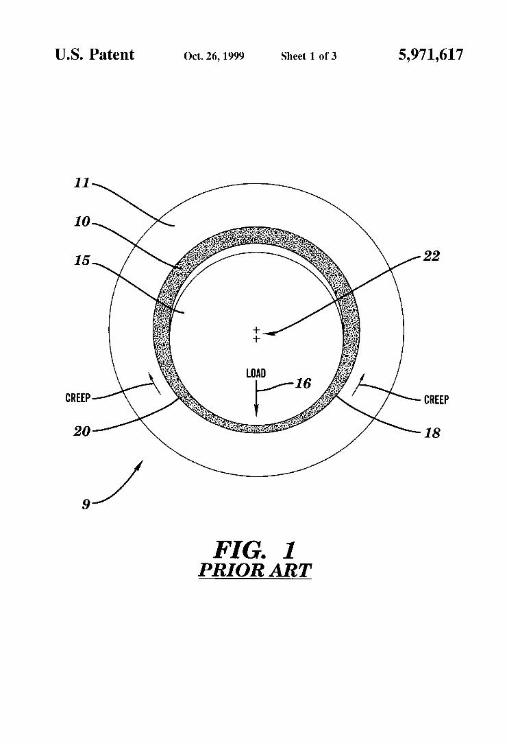
FIG. 1 is a schematic end vieW of a maintenance-free bearing of the prior art, fabricated as a journal bearing and supporting a shaft therein;
FIG. 2 is a perspective vieW, on an enlarged scale, of portions of a bearing of the present invention; and

5,971,617 3
FIG. 3 is a cross-sectional vieW talken along 3—3 of FIG. 2, Which illustrates the portions of a bearing shoWn in FIG. 2, With a sliding or bearing layer disposed thereon.
DETAILED DESCRIPTION OF THE PREFERRED EMBODIMENTS
Brie?y described, as shoWn in the drawings, the present invention comprises a self-lubricating bearing 110 fabri cated as a laminate of a metallic backing, support or sub strate 112, a series of raised structures 113 extending orthogonally therefrom, and a polymeric sliding, Wear or load bearing layer 114 superposed thereover. Raised struc tures 113 preferably are fabricated from bronZe, fastened integrally to substrate 112 and embedded into load bearing layer 114.
Structures 113 serve to maintain load bearing layer 114 in place to help prevent it from sliding along the surface of substrate 112 during bearing operation. This improved anchorage to the substrate enables a relatively thick bearing layer to be utiliZed With a reduced tendency to creep. Alternatively, structures 113 provide a bearing 110, fabri cated With a relatively thin load bearing layer 114, With a friction coef?cient that remains relatively constant over its life. Moreover, structures 113 act as thermal and electrical bridges for relatively high heat and electrical conductivity betWeen support 112 and a supported article such as a rotating shaft. The raised structures thus may act as bound aries surrounding and retaining discrete pockets of self lubricating material locally available for lubrication but unable to escape therefrom during bearing operation. Struc tures 113 also may be in direct contact With the supported article to help prevent bedding-in. Thus, advantageously, bearings 110 are provided With a relatively loW coef?cient of friction, long bearing life, resistance to creep and mechani cal stresses, and are electrically and thermally conductive.
Throughout this disclosure, the terms “self-lubricated” or “self-lubricating” shall refer to use of a material that exhibits sufficient lubricity to nominally eliminate the need for application of a discrete lubricant to a bearing surface.
Referring noW to the draWings in detail, the effect of creep is shoWn in FIG. 1 relative to a prior art journal bearing 9 fabricated With a metal housing 11 and a maintenance free bearing 10 including a plastic load bearing layer as generally described hereinabove. Bearing 10 is adapted to support a shaft 15 Which is Weighted to apply a load in the direction indicated by arroW 16. In response to this loading, the load bearing layer tends to creep or become displaced in the direction indicated by arroWs 18 and 20 (“radial creep”) as Well as in the axial direction (“axial creep”, not shoWn) Wherein the shaft effectively “beds in” to bearing 10. Disadvantageously, this action generates a loss of center alignment of shaft 16 as shoWn at 22.
Referring noW to FIGS. 2 and 3, the present invention comprises a bearing 110 having a backing or substrate 112 fabricated from a metallic or other material capable of providing bearing 110 With requisite structural integrity for an intended application. As shoWn, raised structures 113 are preferably fabricated as integral components of an interme diate layer 116 that extends continuously in a superimposed manner over a surface 118 of support 112. In a preferred embodiment, structures 113 comprise a generally honeycomb-like pattern substantially as shoWn, but may hoWever, be fabricated With substantially any geometric pattern suf?cient to provide anchorage for the Wear layer, as Will be discussed hereinafter. For example, structures 113 may comprise a series of connected or discontinuous poly
15
25
35
45
55
65
4 gons such as squares, circles, triangles etc., or may comprise a series of discrete posts (not shoWn) that extend approxi mately orthogonally relative to surface 118 of support 112. As shoWn, in a preferred embodiment, layer 116 has a thickness t of approximately 60 microns (u), structures 113 have a height h of approximately 100p, a Width W of approximately 50” and are spaced to de?ne an interior dimension d of approximately 300p. Moreover, the skilled artisan Will recogniZe that a small degree of conicity of structures 113 is preferred to facilitate manufacture of the structures using an embosser or a mold.
As shoWn in FIG. 3, load bearing layer 114 is laminated to structures 113 and intermediate layer 116, being bonded thereto by a layer of adhesive 120. Thus, as shoWn, struc tures 113 are embedded Within load bearing layer 114, With the bearing layer having a substantially smooth outermost surface 122 disposed a predetermined orthogonal distance v from structures 113. Distance v may be varied depending on the intended application for bearing 110.
Substrate 112 may be fabricated from various metals, including steel or aluminum, as Well as additional materials such as stainless steel, conventional draWing quality sheet steel, brass or other alloys, or from plastics, ceramics or composites utiliZing glass or carbon ?bers. Surface 118 thereof may be left untreated, or treated using various techniques such as galvaniZing, chromate or phosphate treatments, anodiZing (in the case of an aluminum substrate), mechanical sandblasting and/or chemical pickling. It is also contemplated that a steel substrate coated With porous bronZe, such as utiliZed in the aforementioned DU bearing, may be utiliZed in the fabrication of the present invention. Moreover, substrate 112 may be provided With structures 113 by a discontinuous laser beam Which, by selectively hitting surface 118 and melting it over a relatively small area, creates regularly spaced craters over surface 118 thereof. Load bearing layer 114 may comprise any number of
suitable lubricious substances, such as a polymer or plastic material, including a ?uoropolymer, for example, the com pounds disclosed in US. Pat. No. 5,573,846, entitled POLY FLUOROCARBON COATED METAL BEARING Which issued on Nov. 12, 1996 and Which is hereby incorporated by reference. Preferred plastic materials generally include tem perature tolerant polymer systems containing high melt temperature organic polymers, and/or systems characteriZed by a relatively loW coef?cient of friction. The materials have to be suitable for application or lamination to the material from Which the substrate is fabricated. In this regard, ?uo ropolymers are the preferred adhesives. For example, by selecting an appropriate adhesive layer 120, nominally any organic polymer may be laminated as the load bearing layer 114 to a metal substrate.
Examples of useful polymeric materials in load bearing layer 114 include ?uoropolymers (e.g., polytetra?uoroeth ylene (PTFE), ?uorinated ethylene-propylene (FEP), poly vinylidene ?ouride (PVDF), polychlorotri?uoroethylene (PCTFE), ethylene-chlorotri?uoroethylene (ECTFE), and per?uoroalkoxy polymer (PFA)), acetal, polycarbonate, polyimides, polyetherimide, polyether ether ketone (PEEK), polyethylene, polypropylene, polysulfones (e.g., polyethersulfone), polyamide (Nylon), polyphenylene sul?de, polyurethane, polyester, polyphenylene oxide, and blends and alloys thereof. In addition, PPS, PPSO2 and aromatic or aliphatic polyketone/ethers, PEI and/or Nylon 46 may be utiliZed as the continuous matrix. Reactive polymers, such as polyimides, in solid form (unreacted ?lm) or in solution may be utiliZed. These reactive polymers may

5,971,617 5
thus constitute the continuous matrix. Other polymers such as very high molecular Weight polyethylene (Which can then be bonded With loWer temperature adhesives such as ethyl ene vinylacetate (EVA)), or polyamides also may be utiliZed. Moreover, it is contemplated that the bearing layer may be perforated for additional lubrication by grease pockets dis posed therein.
Lubricants or ?llers are useful. These include various additives that affect polymer characteristics such as lubricity, mechanical strength, Wear resistance and thermal and electrical conductivity. Useful additives include, but are not limited to, a minor volume percentage (e.g., 0.5 to 49.5 percent) of glass and/or carbon ?ber, silicone, graphite, molybdenum disul?de, aromatic polyester, carbon particles, bronZe, ?uoropolymer and combinations thereof.
The choice of a particular material for a given application may be made based on the coef?cient of friction of the material. The coef?cient of friction betWeen tWo surfaces is de?ned in the CRC Handbook of Chemistry and Physics (62nd Edition, 1981-1982) as the ratio of the force required to move one surface over the other to the total force pressing the tWo together. Thus, if F is the force required to move one surface over another and W, the force pressing the surfaces together, the coef?cient of friction p is provided by the formula p=F/W.
For relatively ordinary or light duty applications, accept able materials include those that have a static coef?cient of friction p at least beloW that of steel on steel (0.58) and preferably similar to that of polyethylene (0.2). In heavier duty applications, such as for automotive or general indus trial use, materials having relatively loWer coef?cients are preferred. Preferred materials for these applications are those that, for example, have a coef?cient of static friction (11) similar to that of PTFE (approximately 0.04—0.10).
Although the above static coef?cients may be useful for general comparison, the coef?cients of dynamic or kinetic friction are more meaningful in the context of the present invention in light of the continuous and/or repetitive duty applications typically associated With bearings. The test described beloW Was used for determining and comparing values for the coefficients of dynamic friction for various materials. In the test a series of disks of predetermined dimensions are fabricated, each having a plastic or load bearing layer of a particular material to be tested. The load bearing layers of tWo nominally identical disks are pressed against opposite sides of a smooth steel plate at a predeter mined pressure or load W. The steel plate is then pulled out from betWeen the disks at a predetermined velocity. The force F required to remove the plate is measured and then
divided by W to obtain the coef?cient of kinetic friction The test results discussed hereinafter Were obtained using a
loading W of 565 N and the steel plate Was pulled out at a velocity of 50 mm/min. For example, this test typically yields a coef?cient of kinetic friction for ?lled PTFE of approximately 0.08 to 0.1. As mentioned hereinabove, layer 114 may also include
common ?llers. In this regard, since the present invention does not utiliZe a dispersion of PTFE to facilitate penetration thereof into porous bonZe as taught by the prior art, the siZe of ?ller particles is generally not of concern. Rather, use of skived PTFE sheet in a preferred embodiment of the inven tion permits use of ?llers of substantially any particle siZe and concentration provided PTFE is the continuing phase binding the particles together.
Various alternatives are available for adhesive 120. Suit able adhesives include ?uoropolymers, such as PFA, MFA,
10
15
20
25
30
35
40
45
50
55
60
65
6 ETFE, FEP, PCTFE, PVDF, curing adhesives such as epoxy, polyimide adhesives, and loWer temperature hot melts such as EVA and polyether/polyamide copolymer (PebaxTM). As a further alternative embodiment, layers 114 and 120
are fabricated as a monolayer comprising a polymer blend. For example, a blend of PFA/PTFE, produced by melt extrusion (if PFA is predominant) or by sheet skiving (if PTFE is predominant), may be utiliZed to serve as both adhesive 120 and load bearing layer 114. The presence of PFA Will increase the creep resistance of pure PTFE. This effect may be increased by adding ?llers as described hereinabove. Moreover the voids de?ned by structures 113 may be ?lled With a dispersion of the chosen polymer (PTFE, PPS, a combination thereof, etc., possibly With ?llers), the dispersion dried out, then pressed to form load bearing layer 114. For example, polyimide P84 available from Lending Co., preferably containing PTFE as a ?ller, may be coated directly onto the structures 113, the solvent ?ashed off and the polymer fully imidiZed.
Bearing 110 of the present invention is preferably fabri cated by providing a substrate 112 formed as a metallic sheet, With a cladding of bronZe superimposed thereWith to form an integral intermediate layer 116. This cladding or intermediate layer 116 is bonded to substrate 112 using conventional cladding techniques involving application of heat and pressure to form an integrated composite. This composite is then passed through a conventional calender roll engraved With the negative of the desired pattern of structures 113 such as the honeycomb pattern shoWn in FIG. 2. Bearing layer 114 may be subsequently formed by lami nating a conventional sheet of lubricious material, such as PTFE, using a suitable adhesive as described hereinabove. The entire laminate is then preferably inserted into a con ventional press under heat and pressure Wherein load bear ing layer 114 is provided With outermost surface 122 as shoWn in FIG. 3. As formed, bearing 110 is substantially complete. Once so fabricated, the bearing may be formed into various application speci?c con?gurations using con ventional techniques. In addition, a load bearing layer 114 may be laminated on both surfaces of substrate 112 to provide a double-sided bearing.
Bearings 110, fabricated as ?at sheets in the mainer previously described, may be formed into any number of bearing types, such as bushes or journal bearings, thrust Washers, and skid plates, etc. For example, bushes or journal bearings may be formed by cutting the bearing 110 into strips. Each of these strips, in turn, may be formed into holloW cylinders, With load bearing layer 114 disposed on the inside cylindrical surface thereof, similar to that shoWn in prior art FIG. 1, or alternatively, on the outside surface thereof, depending on the particular application. The cylin drical bearings may then be ?anged using techniques famil iar to those skilled in the art, such as, for example, described in the “Norglide, Norton Performance Plastics” catalogue No. PPL-E-067-1, dated November, 1993, (hereinafter the “Norglide catalogue”) and Which is hereby incorporated by reference in its entirety.
Although a preferred method of fabrication has been described, steps thereof may be modi?ed, eliminated or performed in varying sequence. For example, bearing 110 may be alternatively fabricated by forming substrate 112 into a desired con?guration, such as, for example, a cylinder, prior to application of load bearing layer 114 thereon. In this regard, the substrate may be provided With structures 113 as described hereinabove, then fabricated into a tube using any convenient method, With the structures disposed on either the inner, outer, or both cylindrical surfaces thereof.

5,971,617 7
Thereafter, load bearing layer 114 may be applied to the tube in any convenient manner, such as, for example, by spray coating or dipping. Application of the load bearing layer may be performed either before or after ?anging one or both ends thereof. As a variation of this fabrication technique, substrate 112
may be fabricated into a tube, by any conventional method such as hot or cold forming operations, including roll forming, piercing, draWing or extrusion processes to pro duce either seamed or seamless tubes. Once so formed,
8 described hereinabove. The particular DU bearing tested Was one commonly referred to as a type “Nr PG252825F.”
The NG bearing Was fabricated using standard steel sheet laminated With 230” thick skived PTFE sheet (composition 25% carbon/graphite, 75% PTFE) using conventional 25” thick PFA under the conditions described hereinabove With regard to the present invention. The present invention bear ing (PI) Was fabricated as described hereinabove. A sum mary of tests conducted is provided in Table I.
TABLE I
Test Number Test Type
Present Invention (PI) compared With Conclusions
1 Coe?icient of friction vs. time
2 Resistance to Creep 3 Heat Conductivity
4 Electrical Conductivity 5 Resistance to mechanical
stress
DU PI gives lOW coef?cient of friction over loWer Wear depth
NG PI resists creep better NG PI conducts heat better, particularly With thinner
bearing layers NG PI is better NG PT showed no delamination When ?anged
structures 113 may be provided using a surface texturing technique such as a chemical etching process or the afore mentioned laser treatment. Load bearing layer 114 may be applied thereafter, as previously discussed.
The invention is explained in greater detail by the fol loWing examples and tests.
In one example of a preferred embodiment of the present invention, a support 112 Was formed as a sheet of steel quality St4 1.0338 LG according to the German Industrial Speci?cation (Deutsche Industrie Norm) “DIN 1624”. This sheet Was provided With a thickness of 0.8 mm, including a bronZe cladding approximately 80” thick (bronZe quality CuSn 6). Structures 113 Were formed by passing support 112 through a conventional calender roll engraved With the negative of the desired honeycomb pattern shoWn in FIG. 2. The dimensions of the structures 113 forming the honey comb pattern Were substantially as described hereinabove and shoWn in FIGS. 2 and 3. Load bearing layer 114 Was then formed by laminating a conventional skived PTFE compound sheet (composition 25% carbon/graphite, 75% PTFE) using an adhesive 120 of conventional 25” thick PFA (Te?on® PFAby DuPont®). Parameters of the bearing layer 114 Were predetermined to provide a thickness v (FIG. 3) above structures 113 of approximately 30”. This composite Was then inserted into a conventional press under a load of 4 MPa and a temperature of approximately 375° C. The temperature and pressure Was maintained constant for approximately 3 minutes, then cooled to approximately 100° C. under the same load, folloWed by release from the press.
The resulting laminate Was cut, trimmed and formed to desired geometries.
In another example, support 112 Was a sheet of 0.8 mm thick aluminum (quality AlMg 04 Si 1.2) With both faces treated With chromic acid according to methods Well knoWn in the art, commonly referred to as chromate conversion coating, at 700—800 mg/m2. Remaining fabrication steps Were substantially identical to the example discussed here inabove to produce similar bearings 110.
A series of comparative experiments have been carried out to shoW the improvements of the present invention (PI) relative to the prior art DU and Norglide (NG) bearings
30
35
40
45
50
55
60
65
The tests for coefficient of friction Were conducted on
small (10 mm diameter) disks of each of the DU, NG and PI bearings. Predetermined amounts of the bearing surfaces thereof Were alternately removed from outermost surface 122 thereof, then the coefficient of friction measured. This provided a pro?le of the coefficient of friction of each of the bearings at various depths or degrees of Wear Within the bearing life. The tests Were conducted utiliZing test meth odology disclosed hereinabove. The results are shoWn in the folloWing Table II.
TABLE II
Material Removed from Bearing Layer Friction Coef?cient
(u) DU NG PI
0 0.09 0.10 0.08 9 0.10 _ _
20 0.14 0.10 0.08 30 0.16 0.10 0.09 50 0.18 0.10 0.09 60 0.19 _ 0.09
80 _ 0.09 0.10
110 _ 0.09 0.13
140 _ _ 0.17
160 _ 0.10 0.19
These results indicate the coefficient of friction of the DU bearing begins to increase relatively early in its life. Moreover, the friction coefficient is not constant, so that the assembly (for example, a rotating shaft and housing) Will not encounter the same operating conditions such as smoothness and heat evolution over its life. The value of 0.19 at a depth of 60” is the friction
coefficient betWeen pure bronZe and steel, Which thus indi cates that the available depth of lubricating material from the initial outermost surface 122 is approximately 60”. This amount is considerably less than the total theoretical depth of the mixture of PTFE/bronZe of 250—350p of the DU bearing.
The present invention, hoWever, shoWs a relatively long plateau of loW friction values up to approximately 80p. This result is surprising because one Would expect this plateau to

