self excitation of induction motors with series capacitors
TRANSCRIPT

S1V kA. . { I I . K jAll impedances are expressed in per unit-e 1 t- cxcitatilon oP |neuction Ivlotors quantities which are the same as per cent,,
except that unity is taken as a base in-
W~Vitk Series Capacitors stead of 100. The loss in the resistor-P ~~~~~~1-s- r. represents the shaft power.
S
C. F. WAGNER The lower circuit is the same as theFELLOW AIEE upper one, except that it is resonant for a
frequency f times the system frequency.It is assumed that the source has zero im-
NDUCTION motors with series capaci- may originate in two ways. First, they pedance, and since it has no emf of reso-tors connected in the supply circuit can may be forced by an externally applied nant frequency, this point of the circuit is
under certain conditions become un- voltage in which case the frequency of merely represented by a line of zero im-stable. Upon application of the voltage the currents corresponds to that of the ap- pedance. After connection of the motorthe rotor will come up to partial speed plied voltage. Second, they may flow in to the system voltage, the speed increasesand continue to rotate at this reduced accordance with the natural frequency of until it reaches a value equal to that cor-speed. This phenomenon should not be the circuit. In the latter case, the cur- responding to the synchronous speed as-confused with ferro-resonance which is rent flows in response to some change in sociated with the frequency f. Beyondaccompanied by violent wave distortion, the circuit and gradually decays to zero, this speed, its slip, si, with respect to theabnormally large magnetizing currents, the rate being dependent to a large extent synchronous speed of the resonant circuitand fluctuations in voltage. Both of these upon the resistance. The smaller the re- becomes negative, and with regard to this.phenomena were analyzed as applied to sistance the longer will the currents per- circuit the motor begins to function as aninduction motors by Butler and Con- sist. If a negative resistance, such as induction generator. Since s1 is negative,cordia.' It is the purpose of this paper may be obtained by certain combinations then the resistor (1-sl)rr/sl is negativeto present further thoughts regarding the of vacuum tubes, is inserted into the cir- and the shaft power, which is representedstability problem. A new approach is cuit and is of such characteristic as to just by the loss in this resistor, is also negative.utilized which is much simpler and at equal the positive resistance, then cur- Thus, st so adjusts itself that the nega-the same time provides a clearer con- rents of the natural frequency of the cir- tive resistor (1-s1)rr/s1 just annuls theception of the physical processes in- cuit flow continuously. This is the kind of effect of the two other positive resistors r,volved. Somewhat different conclusions condition that may exist in an induction and rr; the circuit will self excite and theresult with the use of this analysis than motor in which series capacitors are con- currents of frequency f will flow continu-with the analysis of others. In this nected in the stator circuit. ously. The resistor (1-si)r,/s, corre-analysis conventional induction motor The upper circuit of figure 1 shows the sponds to the vacuum tubes mentioned.nomenclature and symbols will be used conventional schematic diagram of an in- previously. The only connection betweenas it is believed that induction motor duction motor in which these otherwise independent circuits is;engineers will better understand theproblem by this procedure.xX =leakage reactance of the stator Paper 41-139, recommended by the AIEE com-
*Xr =leakage reactance of the rotor mittee on electrical machinery, and presented atxm =reactance of the magnetizing branch the AIEE Pacific Coast convention, Yellowstone
Simple Analysis of Problem r, =resistance of stator National Park, August 27-29, 1941. ManuscriptSimple Analysis ofsPrlem r submitted May 23, 1941; made available for pre-rr = resistance of rotor pitn uy2 91XC = capacitive reactance of series capacitor printing July 2, 1941.
Currents in circuits consisting of a ca- s = slip, expressed as a fraction of synchro- C. F. WAGNER is engineering manager of centralof as a fraction of synchro- ~~station section, Westinghouse Electric and Mann-pacitor, inductor, and resistor in series nous speed facturing Company, East Pittsburgh, Pa.
then each row of (28) differs from the cor- second of (17), and the second follows from the same as before, and since the same linearresponding row of the given matrix by a (27); hence B is proved. combination is involved, the correspondinglinear combination of the preceding rows of In solving a sef of m equations in n un- excess column obtained is (with its zeros)(28). The equations corresponding to (28) knowns two unusual cases may arise in identical with that obtained before. It is,(considered as an augmented matrix) determining the auxiliary matrix; however, thus true that each excess column in theare thus equivalent to the original equa- case 1 requires no comment, and we lose auxiliary matrix is obtained in its final form.tions. nothing by supposing the equations to be when first. calculated.A is self-evident. The proof given with written in such an order that this case does Writing the excess columns together and'
(20) and (21) is applicable to (28), and estab- not occur. Turning to case 2, suppose that just to the right of the R columns for thelishes B for the first i rows. For the pth in completing the (i+ 1)th column of the other unknowns, the finished auxiliary-row, p> i, it is true that the [ptb row of (28)1 auxiliary matrix the computed elements, matrix differs from (28) only in that i is,- [pth row of given matrix] -Ap5[1A t row which are identical with A.+,.I+l', Ai+2,±+L', replaced by R. Since the last m -R or mio-eof (28)]-Ap2[2nd row of (28)1]- . . . - .., Am.j+i', all vanish; then this column elements in each excess column in this ma-Ap~, [ith row of (28)1], or is evidently a linear combination of the first trix vanish, it follows from B that for com-
i columns of (28), whence it follows from patibility the last m-R elements of theq-i A and B that the (i+l)th column of the (n+1)th column, which arises from theright
0=Gp-,ApkA k -A q, p> , qg<i given matrix is the same linear combination hand sides of the equations, must alsoIC=1 of the first i columns of that matrix. Were vanish; in which case the last m-R te-.
this excess (i+ 1)th column shifted to any ments of the check column (if one is used)i ~~~~~~~otherposition to the right in the given ma- must vanish due to A.
A p¢ = Gp- A picA Icq p > i, q > i trix, and i or more rows and columns com- In determining the final matrix the excesskC=l pleted as usual in the auxiliary matrix be- columns are considered as transposed to the
fore applying (27) to obtain a matrix similar right hand side of the equations, which factFor here the first equation follows from the to '(28); then since the first i columns are gives rise to minus signs in the column labels.
1941, VOL. 60 Wagner- Self-Excitation of Induction Motors 1241

-jXc r JJXs IXr rr "f- Figure 1. Schematic results by dividing x, everywhere it ap-diagram of induction pears by f and multiplying the inductivemotor with series reactances by f. In this paper all re-
APPLIED -s [**] motor~~~~I- capacitorAPPLIED g ixm _S-rr actances, both inductive and capacitive,VOLTAGE cwill be given in terms of their values at
_________________________________________ _ r rsystem frequency. The two resistancesXFORCED OR 60-CYCLE CIRCUIT U J in the rotor can be combined into the
_- fc f single resistor rr/sl. Upon paralleling thejfx ifxr r condensive branch with xrn a-nd adding to
Fl W 0 the rotor impedances, the impedance asIjfxm | S,r 0 |ISIviewed from a point in the rotor becomesfx. SI rr
ljxm[rs+j(xs-Xc)] rr
theshaft. Power is taken by the shaftjrs+j(xm+Xs-Xc)±+X T+ ( S)NATURAL OSCILLATING OR RESONANT CIRCUIT or
JXm [rs+j(x -xC)] [rs-j(xm+xs-xc)] +the shaft. Power is taken by the shaft from which rsl+(XM+Xg-XC)2from the upper circuit and fed back into s (1 (2 rjthe lower circuit. The current flow in the -)f ) -+jx,=0 (4)lower circuit is limited only by the amount Quantitative Relationsof power that can be drawn from the up- The condition that the circuit be self-per circuit at the particular speed neces- Consider next the conditions which exiting is satisfied when both the realsary to make the resistanee of the lower . . and the imaginary components of thecircuit zero. This power appears as a mus. Tbestsfidtopermitnu oilla- above impedance are individually equal to
negative quantity in the branch which tos. he r sonant ei cult of figure 1 zero. Equating the imaginary componentt h ftIdi d t I must have an impedance equal to zero as to zero, there is obtainedrepresents shaft loading and must equal viewed from any point in the network.
the 12R loss in the r, and r, branches of vthe resonating circuit. It will be found more convenient for the xmrs2+xm(xs-Xc) (Xm+Xs- xC) +
present purpose to view the circuit from a xrrs2+xr(xm+xs x6)2The actual speed, p, of the rotor can beexpressed in terms of both s and si. Thus, point in the rotor circuit. For the sake of from whichthe speed is simplicity in deriving the following ex-
pressions f will first be assumed equal to 2 -X+xM
p= -s= (1-s1)f (1) unity. It will be reinserted in the final s Xm±x8xcJxs+ Xrm (5)
,39 2b
Figure 2. Resonating characteristics of aparticular motor 0.8
0.04 0.15 0.I0 0.04 SPEED
PlC r5 X-Xr rr 0.7 - rr O4A-Xm 2.0 °L
SI rS-124 024 WanrSl-Ectto of\004ootr IE RNSCIN
o5 --z
-10 0.20.--o ~~~~FREQUENCY- -
-8-- - - - - ij.4- _w-0.
-6 0.12D .0
r F~~~~~~~~~~~~~~~~~~~~~~~~~~~r
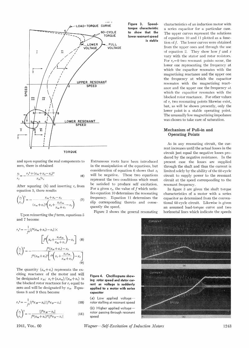
LOAD-TORQUE CURVE Figure 3. Speed- characteristics of an inductiol motor withLOAD-TORQUE CURVE
torque characteristic a series capacitor for a particular case.60-CYCLE to show that the The upper curves represent the solutionsTORQUE lower resonant speed of equations 10 and 11 plotted as a func-
/ tLOWER L FULL is stable tion off. The lower curves were obtained/ VOLTAGE VOLTAGE from the upper ones and through the use
IT / 2 / r' /of equatioii 2. They show how f and s
vary with the stator and rotor resistors.For r,=0 two resonanit points occur, thelower one representing the frequenicy atwhich the capacitor resonates with themagnetizing reactance and the upper onethe frequency at which the capacitor
SUPPER RESONANT resonates with the magnetizing react-SPEED //anec and the upper one the frequency at
a.which the capacitor resonates with the
<n blocked rotor reactance. For other values
of rt two resonating points likewise exist,but, as will be shown presently, only thelower point is a stable operating point.
- g 1/The unusually low magnetizing impedance
k b n c/ LOWER RESONANT was chosen to take care of saturation.0 IJ l /a SPEED
V miY Mechanism of Pull-in and
v I L.. tIOperating Pointsa$ $ As in any resonatilng circuit, the cur-
e f rent increases until the actual losses in theTORQUE circuit just equal the negative losses pro-
duced by the negative resistance. In theand upon equating the real components to Extraneous roots have been introduced present case the losses are suppliedzero, there is obtained in the manipulation of the equations, but through the shaft and thus the current is
r2,'+(x.+x.,-xcl 2consideration of equation 6 shows that s, limited solely bv the ability of the 60-cyclesi rs2++(Xr+Xs-XC) (6) will be negative. These two equations circuit to supply power to the resonantr. X,n2rs represent the two conditions which must circuit at the speed corresponding to the
After squaring (6) and inserting rS from be satisfied to produce self excitation. resonant frequency.equation 5, there results For a given r., the value of f which satis- In figure 3 are given the shaft torque
equation5,there results fies equation 10 determines the resonating characteristics of a motor with a series(sl82 _ x.+x.-'c (7) frequency. Equation 11 determines the capacitor as determined from the conven-\r/ (+,)2(x X m
X slip corresponding thereto and conse- tional 60-cycle circuit. Likewise is givenX,&+Xr /quently the speed. an assumed load-torque curve and two
Figure 2 shows the general resonating horizontal lines which indicate the speedsUpon reinserting thef term, equations 5
and 7 become
rS2= ''Hf2(xm+xs>xc] x
[(x2(+ Xmn)-rc] (8)
(si\2 fl(Xm+Xs) -Xc\r,J f2(XM+Xr)2Ff2(X + XrXm ) 1X*
X,m+Xr/ e
The quantity (x,,,+xs) represents the ex-citing reactance of the motor and will Figure 4. Oscillograms show-be designated xm; x,+ (xx,n)/(xrn+x,) is ing rotor speed and stator cur-the block-ed rotor reactance for r, equal to rent as voltage is suddenlyzero and will be designated by xB. Fqua- applied to a motor with seriestions 8 and 9 then become capacitor
((a) Low applied voltage-
r,'= __ V-rM-XC] ffXB-XCI (10) rotor stalling at resonant speed
(b) Higher applied voltage-.P2fXxM-XJ) - - (11) rotor passing through resonant _1941, VOL. 60 Wagner-Self-Excitatio of duction Motspeedors124
1941, VOL. 60 Wagner-Self-Excitation of Induction AIotors 1243

corresponding to the upper and lower modes of oscillation. By this is meant in figure 3, the distance, ef, represents theresonant frequencies. On the lower reso- that the transient resulting from any sud- torque available for accelerating the ro-
nant speed the distance oa is the total shaft den change is composed of three terms. tor. As its speed increases, the horizontaltorque. Of this torque ob is required to Two of these terms always have a nega- distance between these two curves con-supply the load requirements. The excess tive time constant, which characterizes a tinues to represent the torque availableab is the torque which when converted to condition wherein the components always for acceleration. When, however, thepower at the particular speed represents tend to decrease. The time constant of point, a, is reached the time constantthe power input into the resonant circuit. the third term may be positive, negative, becomes positive and the current in theIf the applied voltage were lowered so or infinitely large. Expressions for the resonant circuit begins to build up. Thethat the 60-cycle torque curve were re- calculation of these time constants are instantaneous operating point, p, is de-duced to that shown by the dotted line, given in appendix I and figure 5 gives fined so that the distance pg representsthen the power into the resonant circuit numerical values for the third term for the the torque necessary to supply the reso-would be reduced to that corresponding circuit of figure 2 as a function of the speed nant current at that instant (the power in-to the torque bc. Similarly, if the load of the motor. The lower curve gives the put into the resonant circuit) and the dis-torque characteristic were increased there natural frequency of this term and the up- tance, hp, the torque still available forwould be less power available for circula- per curve the time constant. The sig- accelerating the rotor. Consider for a
tion of current in the resonant circuit. nificant facts to be drawn from these moment the locus formed by the move-
The right hand portion of the upper curves are that: ment of the point p. At any instant pcurve of figure 4a represents the steady- 1. At the two resonant speeds the time might happen to lie in any one of the six
state stator current, which can be seen to constants are infinitely large. zones, I to VI, formed by the two resonant
consist of two components. One compo- 2. Below the lower resonant speed and speed lines and the load torque curve. In
nent has the same frequency as that of the above the upper resonant speed, the time zones III and IV since the time constant
60-cycle applied voltage and the other a constants are negative. is positive, pg tends to increase and the
lower frequency corresponding to that Of 3. Between the two resonant speeds the locus has a horizontal component toward
the natural frequency of oscillation. time constants are positive. Thus between the left. Similarly, since the time con-
The point d of figure 3, where the speed- the two resonant speeds the current of this stant is negative in zones I, II, V, and,VItorque curve intersects the upper resonant term of the transient tends to increase; at the locus must have horizontal compo-speed line, is the other solution from a all other speeds, to decrease. nents to the right. For zones to the rightcurve, such as shown in figure 2. It is the If voltage is applied to a stationary mo- of the load-torque curve, there stillA,re-purpose of this discussion to show that the tor for which the characteristics are given mains torque available for acceleration
point, a, represents a stable operatingpoint and the point, d, an unstable point. 3.6-.For any particular speed, an inductionmotor with a series capacitor has three
Figure 5. Natural 3.Z - - - - - | - E -+-0.04 Cl frequency and time - - - - - - - -
+ 0.03 l constants of induc-tion motor having 2 - - -
+0.02 0.5 constants of those
+0.01 0.4 shown infgure2 -
0t r=0.04 2". -4-0.01a ~ ~~~~ -0.2 ~20 _-0.01 - a /uw 0L0 0QO 1.0- z 20
1244 agnerSelf-ccifaio o Idcion Moos2IETRNACIN
-0.03 Z% N 00
z 0)o w 1
-.4 w TIME CONSTANT z. I- -ocr IN SECONDS 4
0.4 a-w~~~~~L 0.2~ l 6 -
0.40.0 10 lo
0
z ~~~~~~~~~0.4 ~1 24 0.3 .0.5- -
Z0.6z>.jSIJ_J

sFiure 7. Effect of r =0O. For intermediate values of r8, fseries capacitance for must lie between these two curves.1.2L.00LLLLIL I I <a specic case As pointed out by Butler and Concordia
XM = 3.24 for other cases of instability, this particu-I I IMAXIMIUM STATOR /F H XB= 0.40 lar type also can be alleviated by parallel-RESISTANCE rs ing the capacitor with a resistor. The so-1.0 .0- - -- -. ^ l l l | \ ! / l ] 1 X |lution for this condition is given in the
{{[|8<({ -F-- +1 appendix for the special case in which
0.8 L -8 - - - - 1- - - - there is no series resistance in the stator.X / - RESONATING FREQUENCY The results of calculations employing this0:1 m<79FO r1jMX) ethod are given in figure 8, which gives
0.6 - 0.6 _ 4 7/ _ _ c _ the minimum resistance necessary to sup-0.6 0.C - .- press resonance. Of course, as series re-. . . .. F. - I A, - I I Iisistanceis added to the circuit, the mini-
/ _ j _ _mum parallel resistance increases. When0.4 -0.4 / / RESONATING FREQUENCY the value of series resistance has reached/ . ~~~~~~~FORr5s th ieni0 oaa/ - 5 t t the magnitude given in figure 6, n paral-
0.2 0/2 lel resistance is necessary. This correctivemethod is particularly good because atsystem frequency so little of the current is
0 by-passed but at the lower frequency of0.2 0.4 0.6 0.8 1.0 1.2 resonance sufficient current is by-passedSERIES LINE CAPACITIVE REACTANCE a XC cIN P. U. to prevent resonance effects.
Utilizing the same general approach asof the rotor. Thus zones II, IV, and VI the only difference in the two cases being that given for the development of equa-must have upward components of motion that the applied voltage for (b) was about tions 8 and 9 or that in appendix II, it isof p. Similarly, points to the left of the 3 per cent higher than for (a). In the possible to calculate the parallel resistorload-torque curve tend to decelerate and former case it can be seen that the speed required to suppress resonance for anyhave downward vertical components. The overshoots the final value and finally particular value of series resistance. Thepoint p moves from a with an upward and settles down to the resonant speed. It same method can be extended further toleftward motion, the upward component differs from the story depicted in figure 3 cover any combination of resistors, re-becoming smaller and smaller as the load- in that the resonant current changes so actors, and capacitors.torque is approached. To the left ofj (in rapidly that only the components in zones Test Resultszone III) the locus has a downward and IV and III are of importance. The oscil-leftward component, the leftward com- logram also shows that the resonant fre- In order to verify still further the cor-ponent decreasing with increasing time quency component of the stator current is rectness of the foregoing theory, testsconstant as the lower resonant speed line a maximum a short time after the speed is were made upon a 220 volt, 7'/2 hp, three-is approached at k. Following this reason- a maximum, which conforms to the expec-ing it may be seen that the locus follows tations of the foregoing theory. As the "39-athe spiral and reaches a stable point at b. speed in figure 4b reaches the resonant Xc Xs XrThe foregoing assumed that the inertia speed, the resonant frequency component
of the rotating part was quite high or that of the stator current begins to build up 7AM rr
the power available for acceleration was and then decreases again as the speed ex- Rlow, so that the current had sufficient ceeds the upper resonant speed.time to build up. If on the other hand the 6 -l - - - -above conditions are not fulfilled, the General Results - - - --locus may take a path, such as indicatedby the dashed line, finally attaining the By slight transformation, equation 10stable operating point q. can be rewritten as - - - - - -Note that in neither case did the motor x
tend to operate at point d, the point for __ f2X (12)Iwhich the curves of figure 2 indicated a Xc f X1C Jxc[f (12 - - -solution in the dotted portion of the For specific values of XM/X, and XB/XC - -graphs. If the upper resonant speed is curves of rl/x, similar to that of r, in - - - 15 -greater than 1.0, the rotor must lock in at figure 2 can be plotted as functions of r. 01the lower speed for all cases. It is impossible for the circuit to resonate 2011 --
Verification of the foregoing theory is for x8/xc in excess of the maxima of these --- _presented in figure 4 which shows the curves. These maxima, r,3(max.)/XB, are |- - - -|rotor speed and stator current for the case plotted in figuref6ias afunction of XC/XB lllllllllll(a) inwhich the rotor pulls in atthe reso- and XM/XB. BothXB and xM include the lllllllllllnant speed and (b) in which it passes external series reactance of the motor. ° 0.2 0.4 Thi0.6 .0Ithrough this speed and finally attains a Figure '7 gives the maxima of r8 for xd/x8speed corresponding to normal operating typical values of xMv and XB. In addition, Figure 8. Minimum parallel resistor, Rmin. be-.conditions with a small slip. In both the resonant frequency, f, corresponding low which an induction motor with no seriescases the motor was operating at noload, to r(max.)is also given together withffor stator resisbance will not resonate
1941, VOL. 60 Wagner-Self-Excitation of Induction Motors 1245

phase, wound rotor induction motor. mined by the system frequency character- but the shaft load was increased. For thePower was supplied from a 100 kva, 2,200 istics of the motor. The variations in the maximum load which still permitted thevolt generator. The generating voltage curves of figure 9 are due to the effects of flow of a small resonant frequency cur-was stepped down from 2,200 to 220 saturation. This may at first appear il- rent, the frequency for a voltage of 0.50volts by means of a 15 kw, three-phase logical in view of the fact that the maxi- p.u. was 0.14. This compares favorablytransformer. Capacitors were connected mum terminal voltage is only about 60 with the above value of 0.12 p.u. "fre-in series in the 220 volt side. It was found per cent of rated voltage. However, when quency at the much lower voltage of 0.34that conditions of ferro-resonance were it is recalled that the flux for a given p.u. Fifty per cent voltage under no loadeasily set up for this condition. Resist- amplitude of voltage varies inversely as from figure 9 produces a frequency of 0.19.ance representative of line resistance was the frequency, it may be seen that the in-then inserted in the 2,200 volt side of the fluence of the resonant frequency voltage (b) CHANG1NG ROTOR RESISTANCEcircuit sufficient to suppress ferro-reso- is very great. In addition, the effect of According to equation 11, the slip for
the resonant frequency voltage is not fixed circuit constants is directly propor-measured by the root-mean-square of the tional to the rotor resistance. Figure 10
04 combined voltages but by the sum of the was plotted from data obtained for themaximum values, the lower frequency be- 71/2 hp motor. For each point the volt-ing given greater weight inversely propor- age was decreased to the minimum valuetional to its frequency. for which resonance still persisted so that
- -3_ __ _ _. --_LThe break in the speed curve at 0.13 p.u. the magnetizing impedance was as close as_ synchronous speed represents the lower possible to the unsaturated value. TheSPEED- resonant speed. Below this point the data indicates a substantial check with
speed is determined purely by the nature theory. These tests were niade with ca-U.. - - of the shaft load; the oscillograms show pacitors of 29 ohms and resistors of 44
_ _ / _ohms in the high side of the transformer.
4 I- X X - - - - O- - v (C) CHANGING CAPACITORSo ..,,"'NATURAL FREOUENCY a_ _ - -
zF _ _ us 0.17 0.4 ,w With a 44 ohmi resistor in the high sideo0t. T < T tl > S < AV- of the transformer the capacitors were.__t _ jT °0.16 .3 - -_ -S.Z -7- changed with the results upon the natural. - - -~~~~~~~~~0.6-
O 0.1 0.2 0.3 0.4 0.5 '6 ] 00.E04.0
TERMINAL VOLTS IN P. U. 0 -- - - - - YFigure 9. Variation of speed and natural P0.4 0.l - - -PEEDU.~ ~ ~ 1frequencywithterminalvoltage - - - Oi . -4
0 I1 2 3 4 5 oo
nance. Additional resistance was at times i ROTOR RESISTANCE, r,,IN OHMS ao°. -| !
placed in series in the low voltage side. -Figure 10. Effect of changing rotor resistance - - - - - -
(a) CHANGING APPLIED VOLTAGE °o .I -2 3CAPACITIVE REACTANCE, Xc, IN p. U.
With 0.021 p.u. of capacitance and no evidence of resonant frequency cur-0.071 p.u. of resistance in the high side rents. The minimum frequency at which Figure 11. Effect of capacitive reactance uponand 0.16 p.u. of reactance in the low side currents were discernible was 0.12 p.u. natural frequency for a particular caseof the transformer and the rotor short- In figure 9, as the applied voltage is in-circuited, the applied voltage was varied creased the magnetizing impedance be- frequency shown in figure 11. Calcula-with no load on the shaft except an un- comes lower. Likewise, the ratio xm tions indicated that the frequency shouldloaded d-c generator. From oscillograms XB decreases quite rapidly but XC/XB in- vary approximately as the square root ofit was possible to determine the natural creases but slightly. Thus, the limiting xC. These tests verify this relation.frequency of the resonant currents. In values of r8, as determined from figure 6,figure 9 is plotted the speed and natural decrease. Eventually, therefore, as the Ap d I Ge Izd Afrequency as a function of voltage. It was applied voltage continues to increase the appendix I. Generalized An-impossible to obtain the data for the entire resistance in the stator finally becomes gu lar Velocity of Induction Motorrange by applying the voltage suddenly, greater than the limiting value corre- With Series Capacitorsince for the higher voltages, the motor ac- sponding to the changed constants. Atcelerated through resonant speed to near this point the slope of the speed curve be- The same general procedure will be fol-. . a a . . ~~~lowed as that used by Lyon2 and Ruiden-synchronous speed. The results were oh- comes infniltely large and the speed in- berg 3 Figure 12 shows the schematic dia-tamned by first applying a moderate volt- creases to the normal load speed near syn- gram of the induction motor. The symbolsage and then after steady speed was at- chronous speed and the resonance current are self-explanatory. The instantaneoustamned the voltage was increased gradu- ceases to flow. This corresponds to the culrrent, is, in the stator isally. According to the foregoing theory, observed facts. i =real part [ISe"t]the natural frequency and speed shouldbe For a given terminal voltage, as the =real part [18E(a+if)l] (Al)inldependent of the applied voltage, reso- shaft load is increased, less power remains
. 4 r. . P ~~~~~inwhich Is is complex and m is the general-nant current being limited only by the available to circulate resonant frequency ized angular velocity, a quantity whose realpower input into the shaft for the particu- currents. Thus to check the effect of component determines the variation inlar speed and terminal voltage as deter- saturation the circuit was left the same amplitude with time and whose imaginary
1246 Wagner Self-Excitation of Induction MIotors .AJEE TRANSACTIONS

component determines the angular velocity. constants as a function of p. The other two LettingIn the rotor the current will be designated roots of this equation are relatively unim-by portant because their real parts are nega- Xs+Xm,=XM (B3)
tive. Lettingi, =real part [Ire(m-jP)t] (A2) xrxm (B4)
For the stator the equation can be written m a+Xfxm+Xr- ±if (A13) then the above equation becomes
(rs+mls)IS+-Is+mM(IS+Ir) = 0 (A3) TR 2 R2XmC it can be seen from figure 4 that there are (X,2+R2) X2 -(Xm+XB) R
and for the rotor two rotor speeds for which a is zero (T= - ). LR2+Xc R2+xThe natural frequencies, f, corresponding xMxM=O (B5)
[rr+ (m-jP)lr]Ir+ (m-jp) X to these two points are the values of f foundM(Is+Ir) = 0 (A4) from a solution of equation 8, and the speeds, This can be further reduced to the following
p, are the corresponding values calculated 4Collecting terms from the slips, of equation 9. F, XM2I-XB XMXB
XC xc2[mCr,+m2C(13+M) + 1]I,+ XM+XB 2XMXB 2 XMXB
m2CMIr=0 (AS) Appendix 11. Resistance Shunted x[ +X X2M Xj( + X2 =(m -jp)MIs+ [r7+ (m-jp) X Capacitor
(Ir+M)IIr='0 (A6) C rs is t5 '2Solving equations A3 and A4 for m, there If the resonant frequency, f, is unity, thenresults considering the diagram from figure 8 the is
impedance of the resistor, R, and capaci- sr
[(IS+ M) (Jr+ M) - M2] Cm3+ [rr(ls+ M)+ tance, x,, in series with x, is 1s+ c d r
rss(lr+M)-jPI (Is+-M) (lr+M)-M02H]Cm2+ 2 -jR2X,[rrrsC+ (Ir+ M) -jpr2C(lr+ M)]m+ FR- j XOR
[rr-jp(lr+M)]=0 (A7) R2+XC2 FREQUENCY OF ROTATION=Jp
Now let wo be equal to 2rr times system fre- Upon paralleling this impedance with jx,,, Figure 12. Schematic diagram of inductionquency and and taking rr+jxr in series, there is ob- motor with series capacitor
tained=Xs (A8) f RXC2 [ ] Upon multiplying all inductive reactances
is=(A8) Jxm 2 2+jX- R2+XC22 by f and dividing xc everywhere by f, thereLX, R +XC 1 results
R2XC2 R2 XC 2_2Xl,=x(A9 D21 S+j[ s+Xm-RI± 21 [1-flXM+XB XXMXl/R\) +1,iX.iXc L I r~~~~4-jX~~=O Xc f4XcXc f2)
Xm (Al) K XM+BrMX=/0\2M=
(A) (A10) Equating the imaginary component to zero 1 f2 XMcXXXM JXB +
1 Rx _MXC= 1 (All) xm,p' 2( 2 XS-Rx2 0 (B6)
Cox R\2+X,2/ R±+X1C2Xc Xr
p will be expressed as a fraction of co. Then FXXmr R2XC ] X j( RXC2 2+ This equation provides the relation from
Equation A7 becomes L R2+X2 r \R2±XC2 which the results of figure 8 were obtained.
Equation ~ ~ ~ t ASX" 0eoe (BJtX
I(Xs+Xm)(xr+Xr)- X,2] ) +[rr(X84Xm) + (+ X c)2 } =0 (Bi) Referencesrs(xr+xm) -jP (Xs+ Xm) (Xr+ Xm) - Xm2 }] X This equation reduces to 1. ANALYSIS OF SERIES CAPACITOR APPLICATION
m\2 ( X 2 PROBLEMS, J. W. Butler and C. Concordia. AIEE
-)+[rmrS±(Xr+Xrn)XC-jPrs(Xr+Xm)lX (XC2+R2) R2+ TX-Xm)± RANSACTIONS, volume 56, 1937 (August section),
m ( Xrxm N]\ R2Xc 2. TRANSIENT CONDITIONS IN ELECTRIC MA-
--+[rr-jP(xr+xm)]xc=O (A12) Xs+ ) + (Xs + Xm) X CHINERY, W. V. Lyon. AIEE TRANSACTIONS,Xm+xr/J R2+XC2 volume 42, 1923, pages 157-76.
Xrxm 3. ELECTRISCHE SCHALTVORGANGE (a book),Figure 5 gives the solution of the sig- xs+ r m =0 (B2) R. Rudenberg. Julius Springer, Berlin, 1926, pagenificant root of this equation for particular XM+Xo/ 78.
1941, VOL. 60 Wagner-Self-Excitation of Induction Motors 124'7