self-contained interoperable controller model ucp-1© 2010 taco electronic solutions, inc. 1...
TRANSCRIPT

© 2010 Taco Electronic Solutions, Inc. 1
Application Guide 505-006
BZU2 Hydronic Zoning ControlSelf-Contained Interoperable Controller Model UCP-1
SUPERSEDES: September 23, 2010 EFFECTIVE: November 12, 2010
Table of Contents
BZU2 . . . . . . . . . . . . . . . . . . . . . . . . . . . . . . . . . . . . . . 3Overview . . . . . . . . . . . . . . . . . . . . . . . . . . . . . . . . . 3Features. . . . . . . . . . . . . . . . . . . . . . . . . . . . . . . . . . 3
Purpose of This Guide . . . . . . . . . . . . . . . . . . . . . . . . . 3
Representations and Warranties . . . . . . . . . . . . . . . . . 3
Applicable Documentation . . . . . . . . . . . . . . . . . . . . . . 4
Installation Guide . . . . . . . . . . . . . . . . . . . . . . . . . . . . . 4Precautions . . . . . . . . . . . . . . . . . . . . . . . . . . . . . . . 4General . . . . . . . . . . . . . . . . . . . . . . . . . . . . . . . . . . 4Static Electricity . . . . . . . . . . . . . . . . . . . . . . . . . . . . 5Location . . . . . . . . . . . . . . . . . . . . . . . . . . . . . . . . . . 5FCC Compliance . . . . . . . . . . . . . . . . . . . . . . . . . . . 5
Before Installing . . . . . . . . . . . . . . . . . . . . . . . . . . . . . . 6About this Document . . . . . . . . . . . . . . . . . . . . . . . . 6Inspecting the Equipment . . . . . . . . . . . . . . . . . . . . 6What is Not Included with this Equipment . . . . . . . . 6Equipment Location . . . . . . . . . . . . . . . . . . . . . . . . . 6Selecting a Power Source . . . . . . . . . . . . . . . . . . . . 6
Installation . . . . . . . . . . . . . . . . . . . . . . . . . . . . . . . . . . 7Mounting the Device . . . . . . . . . . . . . . . . . . . . . . . . 7Routing Cabling to the Device . . . . . . . . . . . . . . . . . 8Grounding the Device . . . . . . . . . . . . . . . . . . . . . . . 9
Wiring Information . . . . . . . . . . . . . . . . . . . . . . . . . . . . 9Connecting Input Devices . . . . . . . . . . . . . . . . . . . 12Connecting Output Devices . . . . . . . . . . . . . . . . . . 13Other Connections . . . . . . . . . . . . . . . . . . . . . . . . . 13
Specifications . . . . . . . . . . . . . . . . . . . . . . . . . . . . . . . 13Electrical . . . . . . . . . . . . . . . . . . . . . . . . . . . . . . . . 13Mechanical . . . . . . . . . . . . . . . . . . . . . . . . . . . . . . . 14
Application Description . . . . . . . . . . . . . . . . . . . . . . . . 15Application Example . . . . . . . . . . . . . . . . . . . . . . . 16
Sequence of Operation . . . . . . . . . . . . . . . . . . . . . . . 17Occupancy and Zone Setpoints. . . . . . . . . . . . . . . 17Outdoor Temperature Limits . . . . . . . . . . . . . . . . . 17Zone Output Operation . . . . . . . . . . . . . . . . . . . . . 17Demand Outputs & BLM Communication . . . . . . . 17Networking Controllers . . . . . . . . . . . . . . . . . . . . . 18Local Backup Schedule . . . . . . . . . . . . . . . . . . . . . 18Additional Features . . . . . . . . . . . . . . . . . . . . . . . . 19System Tuning. . . . . . . . . . . . . . . . . . . . . . . . . . . . 19Automatic Configuration . . . . . . . . . . . . . . . . . . . . 19
Controller Identification . . . . . . . . . . . . . . . . . . . . . . . 20Inputs . . . . . . . . . . . . . . . . . . . . . . . . . . . . . . . . . . . 20Outputs . . . . . . . . . . . . . . . . . . . . . . . . . . . . . . . . . 20Configuration . . . . . . . . . . . . . . . . . . . . . . . . . . . . . 21Alarms . . . . . . . . . . . . . . . . . . . . . . . . . . . . . . . . . . 22
Troubleshooting . . . . . . . . . . . . . . . . . . . . . . . . . . . . . 23Diagnostic LEDs . . . . . . . . . . . . . . . . . . . . . . . . . . 23Troubleshooting Tips . . . . . . . . . . . . . . . . . . . . . . . 24

iWorX® BZU2
2 505-006, Effective: November 12, 2010 © 2010 Taco Electronic Solutions, Inc.
THIS PAGE LEFT BLANK INTENTIONALLY

iWorX BZU2
505-006, Effective: September 23, 2010 3 © 2010 Taco Electronic Solutions, Inc.
BZU2The BZU2 hydronic zoning control is a microprocessor-based controller for adding additional heating zones to hydron-ics systems that are being controlled by an iWorX BLM Series boiler controller. It may also be used as a stand-alone zone controller. This application includes control of up to five heating zones and a general heat demand.
OverviewFive analog inputs are provided for zone temperature sensors. A digital input is available for a plant alarm. Up to five zone valves or pumps are controlled by digital outputs. An additional digital output is provided for a heat demand out-put.
The controller is based on the LONWORKS® networking technology, and communicates with the BLM Series controller over the network. The controller can also be networked to a higher-level control system for monitoring and control applications.
Features• Control of up to five heating zones with individual sensor inputs and outputs• Networking capability of up to 24 units (120 zones)• Individual temperature setpoints for occupied heating of each zone• Common temperature setpoint for unoccupied heating• Proportional plus integral (P+I) control of heating• Heat demand output for a common pump or non-networked heat source• Heat demand and zone demand are communicated to a BLM Series boiler control• Outdoor cutoff temperatures available when used with a BLM Series or ASM2 Controller• LONWORKS® interface to building automation systems and host products• Automatic configuration with a Local Control Interface (LCI) touchscreen• Alarm/Event reporting• LonWorks interface to building automation systems
PURPOSE OF THIS GUIDEThe iWorX BZU2 Application Guide provides application information for the BZU2 Controller.
The reader should understand basic HVAC concepts, intelligent environmental control automation, and basic LON-WORKS networking and communications. This Application Manual is written for:
• Users who engineer control logic• Users who set up hardware configuration• Users who change hardware or control logic• Technicians and field engineers
REPRESENTATIONS AND WARRANTIESThis Document is subject to change from time to time at the sole discretion of Taco Electronic Solutions, Inc. All updates to the Document are available at www.taco-hvac.com. When installing this product, it is the reader’s responsi-bility to ensure that the latest version of the Document is being used.

iWorX BZU2
4 505-006, Effective: September 23, 2010 © 2010 Taco Electronic Solutions, Inc.
The iWorX BZU2 shall only be used for the applications identified in the product specifications and for no other pur-poses. For example, the iWorX BZU2 is not intended for use to support fire suppression systems, life support systems, critical care applications, commercial aviation, nuclear facilities or any other applications where product failure could lead to injury to person, loss of life, or catastrophic property damage and should not be used for such purposes.
Taco Electronic Solutions, Inc. will not be responsible for any product or part not installed or operated in conformity with the Document and instructions or which has been subject to accident, disaster, neglect, misuse, misapplication, inade-quate operating environment, repair, attempted repair, modification or alteration, or other abuse. For further informa-tion, please refer to the last page of this Document for the company’s Limited Warranty Statement, which is also issued with the product or available at www.taco-hvac.com.
APPLICABLE DOCUMENTATION
INSTALLATION GUIDE
PrecautionsGeneral
This symbol is intended to alert the user to the presence of important installation and maintenance (servic-ing) instructions in the literature accompanying the equipment.
WARNING: Electrical shock hazard. Disconnect ALL power sources when installing or servicing this equipment to prevent electrical shock or equipment damage.
Make all wiring connections in accordance with these instructions and in accordance with pertinent national and local electrical codes. Use only copper conductors.
Part Number Audience PurposeiWorX BZU2 Application Guide, Document No. 505-006 (this docu-ment)
– Application Engineers– Wholesalers– Contractors
Provides specific application information about the BLM series, including sequence of operation and configuration information.
iWorX LCI2 Application Guide, Document No. 505-002
– Application Engineers– Installers– Service Personnel– Start-up Technicians– End user
Provides instructions for setting up and using the iWorX Local Control Interface.
iWorX DXU3 Application Guide, Document No. 505-004
iWorX DXU4 Application Guide, Document No. 505-005
– Application Engineers– Installers– Service Personnel– Start-up Technicians– End user
Provides specific application information about the DXU series, including sequence of operation and configuration information.
http://iWorxWizard.taco-hvac.com – Application Engineers– Wholesalers– Contractors
An on-line configuration and submittal package gen-erator based on user input. Automatically generates bill of materials, sequence of operations, flow dia-grams, wiring diagrams, points and specifications.
Additional Documentation
LonWorks FTT-10A Free Topology Transceiver User’s Guide, published by Echelon Corpo-ration. It provides specifications and user instructions for the FTT-10A Free Topology Trans-ceiver.

iWorX BZU2
505-006, Effective: September 23, 2010 5 © 2010 Taco Electronic Solutions, Inc.
Static ElectricityStatic charges produce voltages that can damage this equipment. Follow these static electricity precautions when han-dling this equipment.
• Work in a static free area.• Touch a known, securely grounded object to discharge any charge you may have accumulated.• Use a wrist strap when handling printed circuit boards. The strap must be secured to earth ground.
LocationAvoid locations where corrosive fumes, excessive moisture, vibration or explosive vapors are present.
Avoid electrical noise interference. Do not install near large contactors, electrical machinery, or welding equipment.
This equipment is suitable for indoor or outdoor use. Preferably, or as required by National Electrical Code, the unit is intended to be installed within an electrical control enclosure. Operate where ambient temperatures do not exceed 140 °F (60 °C) or fall below 32 °F (0 °C) and relative humidity does not exceed 90%, non-condensing.
FCC ComplianceThis equipment has been tested and found to comply with the limits for a Class A digital device, pursuant to Part 15 of the FCC rules. These limits are designed to provide reasonable protection against harmful interference. This equip-ment can radiate radio frequency energy and, if not installed and used in accordance with the instructions, may cause harmful interference to radio communications. However, there is no guarantee that interference will not occur in a par-ticular installation. If this equipment does cause harmful interference to radio or television reception, which can be determined by turning the equipment off and on, the user is encouraged to try to correct the interference by one or more of the following measures:
• Reorient or relocate the receiving antenna.• Increase the separation between the equipment and the receiver.• Connect the equipment to a power source different from that to which the receiver is connected.• Consult the equipment supplier or an experienced radio/TV technician for help.
You are cautioned that any changes or modifications to this equipment not expressly approved in these instructions could void your authority to operate this equipment in the United States.

iWorX BZU2
6 505-006, Effective: September 23, 2010 © 2010 Taco Electronic Solutions, Inc.
BEFORE INSTALLINGAbout this DocumentThe instructions in this manual are for the BZU2 module, which supports five heating zones.
Inspecting the EquipmentInspect the shipping carton for damage. If damaged, notify the carrier immediately. Inspect the equipment for damage. Return damaged equipment to the supplier.
What is Not Included with this Equipment• A power source for the equipment electronics and peripheral devices.• Tools necessary to install, troubleshoot and service the equipment.• The screws or DIN rail needed to mount the device.• Peripheral devices, such as sensors, actuators, etc.• Cabling, cabling raceway, and fittings necessary to connect this equipment to the power source, FTT-10A network
and peripheral devices.
Equipment LocationAbide by all warnings regarding equipment location provided earlier in this document.
Optimally, the equipment should be installed within a secure enclosure.
The equipment must be installed indoors unless contained within a protective enclosure. The enclosure must maintain internal temperature and humidity within the ranges specified for this equipment.
The equipment must be installed within 500 feet of all input peripherals (smoke detectors, sensors, etc.) that will be connected to the equipment. It must be within 200 feet of any connected thermostats.
Selecting a Power SourceThis equipment requires a UL recognized external power source (not supplied) to operate. The controller power input requires a voltage of 24 Volts AC.
To calculate power source current requirements, add the power consumption of all peripheral devices to that of the controller.
The controller and triac output loads can use the same power source. If both are using the same power source, the loads must have EMF protection. This protection can be integral to the load, or installed in the 24 VAC wiring across the load’s coil.
To provide necessary RFI and transient protection, the controller’s ground (GND) pin (T40) must be connected to earth ground or the earth ground of the packaged unit’s enclosure ground. Failure to properly ground the controller may cause it to exceed FCC limits. Excessive noise could also produce inaccurate sensor data. The power source must be capable of operating with this connection to ground.

iWorX BZU2
505-006, Effective: September 23, 2010 7 © 2010 Taco Electronic Solutions, Inc.
INSTALLATIONWarning: Electrical shock hazard. To prevent electrical shock or equipment damage, disconnect ALL power sources to controllers and loads before installing or servicing this equipment or modifying any wir-ing.
Mounting the Device1.Select a mounting location. Enclosure mounting is recommended. 2.Hold the controller on the panel you wish to mount it on. With a marker or pencil mark the mounting locations on
the panel. 3.Using a small drill bit pre-drill the mounting holes. 4.Using two #6 pan head screws, mount the controller to the panel. 5.Wire the controller (See Routing Cabling to the Device).

iWorX BZU2
8 505-006, Effective: September 23, 2010 © 2010 Taco Electronic Solutions, Inc.
Figure 1: Mounting Dimensions
Routing Cabling to the DeviceCabling used to connect the power source and cabling used to connect the FTT-10A network must remain separated within the control enclosure and wiring conduit.

iWorX BZU2
505-006, Effective: September 23, 2010 9 © 2010 Taco Electronic Solutions, Inc.
Grounding the DeviceThe ground terminal (T40) must be securely connected to earth ground. Failure to properly ground this equipment will result in improper operation. Improper grounding may also increase the risk of electrical shock and may increase the possibility of interference with radio/TV reception.
For best performance, connect the power supply common terminal (T38) to the same external point as the ground terminal (T40).
WIRING INFORMATIONWARNING: Terminals 12, 15, 18 and 38 are connected internally on all BZU2 controllers. Disconnect ALL power sources when installing or servicing this equipment to prevent electrical shock or equipment dam-age.

iWorX BZU2
10 505-006, Effective: September 23, 2010 © 2010 Taco Electronic Solutions, Inc.
Figure 2: BZU2 Power Sourcing

iWorX BZU2
505-006, Effective: September 23, 2010 11 © 2010 Taco Electronic Solutions, Inc.
Figure 3: BZU2 Power Sinking

iWorX BZU2
12 505-006, Effective: September 23, 2010 © 2010 Taco Electronic Solutions, Inc.
Figure 4: BZU2 Power Isolated
Connecting Input DevicesZone Temperature Sensors (ZT1, ZT2, ZT3, ZT4, ZT5)
To connect the Zone Temperature thermistor to the unit, attach one wire from the thermistor to a ZT terminal (T13, T14, T16, T17, T19) and the other wire to an adjacent common (T12, T15, T18). See Figure 2, Figure 3, or Figure 4 for details.The thermistors used must be 10K Precon Type III.
Plant Alarm (ALM)To connect the plant alarm to the digital input, attach one wire of the contact to ALM (T11) and the other wire to the adjacent common (T12).

iWorX BZU2
505-006, Effective: September 23, 2010 13 © 2010 Taco Electronic Solutions, Inc.
Connecting Output DevicesHeating Zones (HZ1, HZ2, HZ3, HZ4, HZ5)
The outputs for the zone valves or pumps must be connected to 24 VAC pilot relays. See Figure 2, 3 or 4 for details.
• Connect HZ1 (T31) to load. Use TC12 as common.• Connect HZ2 (T29) to load. Use TC12 as common.• Connect HZ3 (T28) to load. Use TC34 as common.• Connect HZ4 (T26) to load. Use TC34 as common.• Connect HZ5 (T25) to load. Use TC56 as common.
Heating Demand (DMD)This output may be used to operate a supply pump for the zone circuits or to signal a heat demand to a non-networked boiler control or other heat source. For most applications, this output must be connected to a 24 VAC pilot relay. See Figure 2, 3 or 4 for details.
• Connect DMD (T23) to load. Use TC56 as common.
Other ConnectionsNetwork (LON)
Network wiring must be twisted pair. One network wire must be connected to terminal NETA (T1) and the other network wire must be connected to terminal NETB (T2). Polarity is not an issue since an FTT-10A network is used for commu-nications.
Power (PWR)Connect one output wire from a 24 VAC power supply to PWR (T39) and the other output wire from the power supply to the adjacent common terminal (T38).
Ground (GND)Terminal GND (T40) must be connected to earth ground. Failure to properly ground this equipment will result in improper operation. Improper grounding may also increase the risk of electrical shock, and may increase the possibility of interference with radio and TV reception.
SPECIFICATIONSElectrical
Inputs• Cabling: twisted shielded pair, 18 AWG recommended—500 feet max. (152 meters)• Resolution: 10 bit
Thermistor Inputs• Precon Type III 10K thermistor, precon type II 10K thermistor or Taco Series T101 thru 103
Switch Input• Dry Contact• Nomally closed; software selectable• 5 Volts DC Max
iWorX BZU2
14 505-006, Effective: September 23, 2010 © 2010 Taco Electronic Solutions, Inc.
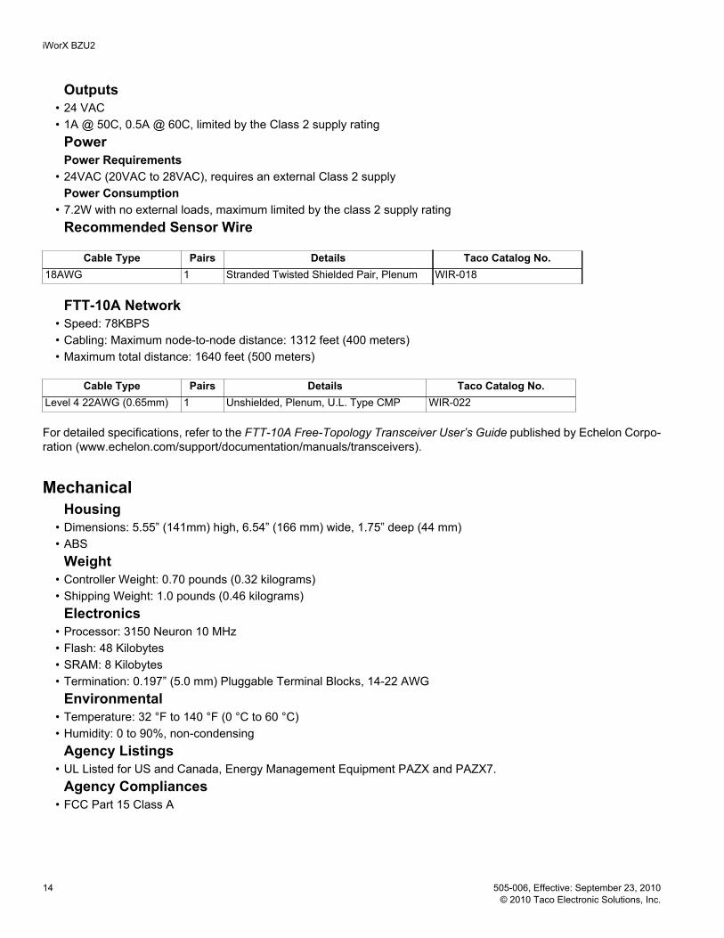
Outputs • 24 VAC• 1A @ 50C, 0.5A @ 60C, limited by the Class 2 supply rating
PowerPower Requirements
• 24VAC (20VAC to 28VAC), requires an external Class 2 supplyPower Consumption
• 7.2W with no external loads, maximum limited by the class 2 supply ratingRecommended Sensor Wire
FTT-10A Network• Speed: 78KBPS• Cabling: Maximum node-to-node distance: 1312 feet (400 meters)• Maximum total distance: 1640 feet (500 meters)
For detailed specifications, refer to the FTT-10A Free-Topology Transceiver User’s Guide published by Echelon Corpo-ration (www.echelon.com/support/documentation/manuals/transceivers).
MechanicalHousing
• Dimensions: 5.55” (141mm) high, 6.54” (166 mm) wide, 1.75” deep (44 mm)• ABS
Weight • Controller Weight: 0.70 pounds (0.32 kilograms)• Shipping Weight: 1.0 pounds (0.46 kilograms)
Electronics• Processor: 3150 Neuron 10 MHz• Flash: 48 Kilobytes • SRAM: 8 Kilobytes • Termination: 0.197” (5.0 mm) Pluggable Terminal Blocks, 14-22 AWG
Environmental • Temperature: 32 °F to 140 °F (0 °C to 60 °C)• Humidity: 0 to 90%, non-condensing
Agency Listings• UL Listed for US and Canada, Energy Management Equipment PAZX and PAZX7.
Agency Compliances• FCC Part 15 Class A
Cable Type Pairs Details Taco Catalog No.18AWG 1 Stranded Twisted Shielded Pair, Plenum WIR-018
Cable Type Pairs Details Taco Catalog No.Level 4 22AWG (0.65mm) 1 Unshielded, Plenum, U.L. Type CMP WIR-022
iWorX BZU2
505-006, Effective: September 23, 2010 15 © 2010 Taco Electronic Solutions, Inc.
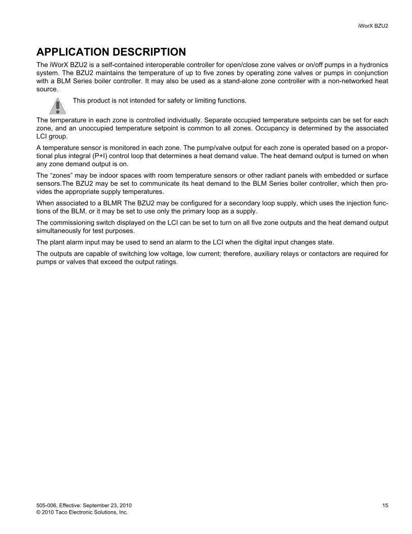
APPLICATION DESCRIPTIONThe iWorX BZU2 is a self-contained interoperable controller for open/close zone valves or on/off pumps in a hydronics system. The BZU2 maintains the temperature of up to five zones by operating zone valves or pumps in conjunction with a BLM Series boiler controller. It may also be used as a stand-alone zone controller with a non-networked heat source.
This product is not intended for safety or limiting functions.
The temperature in each zone is controlled individually. Separate occupied temperature setpoints can be set for each zone, and an unoccupied temperature setpoint is common to all zones. Occupancy is determined by the associated LCI group.
A temperature sensor is monitored in each zone. The pump/valve output for each zone is operated based on a propor-tional plus integral (P+I) control loop that determines a heat demand value. The heat demand output is turned on when any zone demand output is on.
The “zones” may be indoor spaces with room temperature sensors or other radiant panels with embedded or surface sensors.The BZU2 may be set to communicate its heat demand to the BLM Series boiler controller, which then pro-vides the appropriate supply temperatures.
When associated to a BLMR The BZU2 may be configured for a secondary loop supply, which uses the injection func-tions of the BLM, or it may be set to use only the primary loop as a supply.
The commissioning switch displayed on the LCI can be set to turn on all five zone outputs and the heat demand output simultaneously for test purposes.
The plant alarm input may be used to send an alarm to the LCI when the digital input changes state.
The outputs are capable of switching low voltage, low current; therefore, auxiliary relays or contactors are required for pumps or valves that exceed the output ratings.
iWorX BZU2
16 505-006, Effective: September 23, 2010 © 2010 Taco Electronic Solutions, Inc.
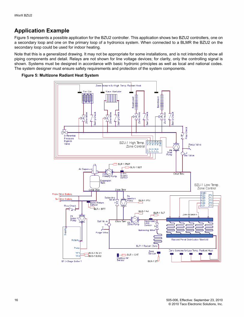
Application ExampleFigure 5 represents a possible application for the BZU2 controller. This application shows two BZU2 controllers, one on a secondary loop and one on the primary loop of a hydronics system. When connected to a BLMR the BZU2 on the secondary loop could be used for indoor heating.
Note that this is a generalized drawing. It may not be appropriate for some installations, and is not intended to show all piping components and detail. Relays are not shown for line voltage devices; for clarity, only the controlling signal is shown. Systems must be designed in accordance with basic hydronic principles as well as local and national codes. The system designer must ensure safety requirements and protection of the system components.
Figure 5: Multizone Radiant Heat System

iWorX BZU2
505-006, Effective: September 23, 2010 17 © 2010 Taco Electronic Solutions, Inc.
SEQUENCE OF OPERATIONThis section describes the detailed sequence of operation for the BZU2 control strategy. The italicized terms refer to the settings available on the LCI. (See “Controller Identification” on page 20.)
Occupancy and Zone SetpointsIndoor Zone Control
The BZU2 is always in an indoor zone control mode. The occupancy of all five zones is determined by the group occu-pancy status communicated from the LCI. At the LCI group level, the occupancy may be scheduled or manually set to the occupied state. At the BZU2 zone level, each zone may be individually forced on by turning the Zone 1/2/3/4/5 Override switch to “On”. When in the unoccupied state, each zone is controlled to the common Unoccupied Setpoint. When occupied, each zone is controlled to its individual Zone 1/2/3/4/5 Occupied Setpoint.
Outdoor Temperature LimitsThe outdoor air temperature (OAT) is communicated from the BLM Series boiler controller to allow for warm weather shutdown. When the OAT is greater than the OAT Heating Cutoff, zone heating is disabled.
At the BZU2 zone level, turning “On” the Zone 1/2/3/4/5 Override switch overrides the outdoor limits for the individual zones.
If there is not a BLM series controller on the network, the OAT is received from an ASM-2 auxiliary sensor module.
Zone Output OperationThe five zone outputs may be used for on/off valves, on/off pumps or other heat sources. If not disabled by the outdoor limits, the outputs for each zone are operated to maintain the zone setpoints established above. The outputs are con-trolled by proportional plus integral (P+I) feedback loops that compare the individual zone temperatures (Zone 1/2/3/4/5 Temperature) with the respective setpoints (Zone 1/2/3/4/5 Setpoint).
When the demand for a zone reaches at least 10%, the output is turned on to open the valve or operate the pump. The output remains on until the demand drops to 5% or less. For each output, a five-second on-delay and a minimum on time of one minute to protect against short cycling. The status of each output is displayed on the LCI (Zone 1/2/3/4/5 Output).
Proportional + Integral TuningThe zone demands are calculated as a percentage such that the value is 1% for every degree centigrade that the tem-perature is below the setpoint, multiplied by the proportional gain. The integral term is added to that percentage to elim-inate any offset. The proportional gains and integral times are adjustable by using the corresponding LCI settings (Zone 1/2/3/4/5 Proportional Gain & Zone 1/2/3/4/5 Integral Time). The proportional gain determines the effective tem-perature differential for the zone. For example, with a proportional gain of “20”, the demand reaches 10% at 0.5°C (0.9°F) below the setpoint (output turned on), and drops to 5% when within 0.25 °C (0.45 °F) of setpoint (output turned off). To operate with a wider differential (less frequent cycling of the output), decrease the proportional gain. The inte-gral time determines how quickly an offset is corrected. To allow the offset to remain for a longer period (resulting in less cycling of the output), set the integral time to a longer period (or set it to zero to disable the integral function).
Demand Outputs & BLM CommunicationWhen any of the zones outputs are turned on, the Heat Demand output is turned on. This may be used to operate a supply pump for the zone circuits or to signal a heat demand to a non-networked boiler control or other heat source. If the BLM Heat Demand setting is “On”, then the status of this output is communicated to the BLM as a primary loop demand. If the outdoor temperature is below the OAT heating cutoff of the BLM, the primary pump is turned on and the boilers are controlled to provide water at the appropriate outdoor reset setpoint.
The greatest of the five zone demands is displayed as the Maximum Zone Demand. If the BZU2 Zone Demand setting is “On”, then this maximum value is communicated to the BLMR as a sub-zone demand for the secondary loop. If the outdoor temperature is below the OAT heating cutoff of the BLM or BLMR, the BLM pump is operated and the injection output is controlled (only with BLMR) to provide the appropriate outdoor reset temperature in the secondary loop. The boilers and primary pump are operated as needed to meet the injection demand.

iWorX BZU2
18 505-006, Effective: September 23, 2010 © 2010 Taco Electronic Solutions, Inc.
If the BZU2 zones are on the secondary loop of a BLMR, only the BLM Zone Demand setting needs to be “On”, since the demand for the boiler is dictated by the injection requirements. This method fires the boiler only as needed. How-ever, both BLMR settings, the BZU2 Heat Demand and the BZU2 Zone Demand may be turned “On”. The effect of this is to create a demand for the boiler whenever a BZU2 zone is calling. This serves to keep the boiler in a standby mode that could reduce cycling as the demand from the secondary loop varies.
Networking Controllers Associations can only be done in a network with an LCI2 present. Please refer to the LCI2 Application Manual for detailed instructions.
Setting the Hydronic ZoneTo associate a DXU type Controller to a BZU2, you start from the BZU2 control screen. Press “Members” to display a list of DXU units on the network. The member status of each is shown in the right-hand column. A member unit is one that operates with shared settings from the BZU2. To change the member status of a DXU controller, just press that controller. It will toggle member or non-member with each press. If a DXU has been selected or deselected, you must press “Save” afterward to confirm the new setting. Only one DXU can be associated to a BZU2.
The BZU will always transmit the first zone settings and space temperature to the DXU.
Associating a BZU2 to a BLMCSince multiple BLMC and BZU2x controllers can be a part of an iWorX system, it is necessary to group these control-lers so that the BLMC knows which BZU2x controllers it may receive a demand from. To associate a BZU2 Controller to a BLM Series Controller start from the BLM control screen. Press “Members” to display a list of the BZU units on the network. The member status of each is shown in the right-hand column. A member unit is one that communicates its demand to the BLM. To change the member status of a BZU2 controller, just press that controller. It will toggle member or non-member with each press. If a BZU2 has been selected or deselected, you must press “Save” afterward to con-firm the new setting. Up to 24 BZU2 controllers can be associated to one BLM Series controller.
Local Backup ScheduleThe LCI normally determines the operating mode. You can define local weekday and weekend backup schedules for situations when the LCI is not available. When the controller detects that the LCI is not available (after 10 minutes with-out communication), it resorts to the local backup schedules that you have configured. If the local backup schedules are disabled, the controller defaults to the occupied mode.
You configure the occupied and unoccupied times that are used in determining the current operating mode of the con-troller when it is running a backup schedule. By default, both the unoccupied and occupied time are set to zero, which disables the local backup schedule. This causes the controller to default to the occupied mode of operation if it cannot communicate with the LCI.

iWorX BZU2
505-006, Effective: September 23, 2010 19 © 2010 Taco Electronic Solutions, Inc.
Additional FeaturesCommissioning Switch
To allow simple commissioning, a single switch setting can be set at the LCI. By setting the Commissioning Switch to “On”, all six digital outputs are turned on simultaneously.
Alarms MonitoringThe controller will detect certain conditions and send them to the LCI as alarms. These alarms are displayed and recorded for later access, but do not alter the system operation.
Temperature Sensor AlarmIf the analog input from a thermistor is outside of the expected range of the thermistor (-29 °F to 230 °F [-33 °C to 110 °C]), this alarm will be sent to the LCI. An alarm of this type is most likely due to a wiring fault causing the input to be shorted or open. An open sensor results in a reading of -29 °F (-33 °C), while a short appears as 230 °F (110 °C).
Zone Temperature AlarmsThe BZU2 generates an alarm for a Zone if the Temperature is well above or below the Setpoint. For occupied mode, the deadband is 1.5 °F (0.83 °C). For unoccupied mode the deadband is 1.5°F (0.83 °C). If the mode changes from unoccupied to occupied, an alarm delay of 30 min will be enforced in order to let the space heat up after a lower tem-perature setpoint.
Plant AlarmA digital input is available to monitor an alarm signal from the system. This may be derived from multiple sources such as limit switches or motor overloads. A dry contact is used to change the state of the BZU2 input. If the alarm is enabled on the inputs screen, the signal generates an alarm at the LCI. The alarm is cleared when the contact returns to the normal state, which may be selected as “Normally Open” or “Normally Closed” on the inputs screen.
System TuningP+I Loops
These parameters control the proportional gain and integral time of the controller’s proportional plus integral (P+I) con-trol loops. Refer to “Proportional + Integral Tuning” on page 17 before changing these settings. the PI Loop parameters are part of the individual Zone Settings on page 22.
Automatic ConfigurationThe BZU2 and iWorX Local Control Interface (LCI) use a self-configuring network management scheme requiring no external tools, binding, or LONWORKS knowledge. The LCI recognizes and configures the BZU2 when the controller’s service pin is pressed. The controller’s status light flashes green until the controller is configured, and will be solid green after the controller is configured. Once the service pin has been pressed, no further action is required by the user; the controller is fully accessible to the LCI. Users may bind to SNVTs on the BZU2 with LNS or other LONWORKStools if they wish.
The LCI also provides network supervision of the BZU2. The LCI periodically sends a "ping" message to the BZU2, which elicits a response. If the response fails, an alarm is displayed on the LCI. The LCI also uses the "ping" message to refresh the occupancy mode and other system wide data.

iWorX BZU2
20 505-006, Effective: September 23, 2010 © 2010 Taco Electronic Solutions, Inc.
CONTROLLER IDENTIFICATIONOnce the BZU2 is properly installed and recognized by the LCI, the LCI touchscreen can be used to configure the set-tings of the controller and to monitor the Inputs, Outputs and Alarms. This section describes the commands available on the LCI for monitoring/configuration of the BZU2, and the meanings and suggested values for controller parameters. For more information on using the LCI, see the iWorX LCI User’s Guide.
InputsThis screen list all the inputs on the BZU-2. These values cannot be changed.
OutputsThis screen list all the outputs of the BZU-2. These values cannot be changed.
Setting Range DescriptionOutside Temp -29 to 230 °F (-33 to 110 °C) Measured OAT as reported from the ASM-2 controllerZone 1 Temp -29 to 230 °F (-33 to 110 °C) Measured temperature of each zone.
-29°F relates to an open sensor230°F relates to a shorted sensor
Zone 2 TempZone 3 TempZone 4 TempZone 5 TempOccupancy Occ,
UnoccOccupancy status of the zone according to schedule or override.
Plant Alarm Normal, Alarm Status of the plant alarm.
Setting Range DescriptionZone 1 Output Off, On Status of each zone output.Zone 2 OutputZone 3 OutputZone 4 OutputZone 5 OutputHeating Demand Off, On Status of the heat demand output.Max Zone Demand 0.00% to 100.00% Highest demand of the five zones.Zone 1 Setpoint 23 to 203 °F (-5 to 95 °C) Current setpoint for each zone.Zone 2 SetpointZone 3 SetpointZone 4 SetpointZone 5 Setpoint
iWorX BZU2
505-006, Effective: September 23, 2010 21 © 2010 Taco Electronic Solutions, Inc.
Configuration
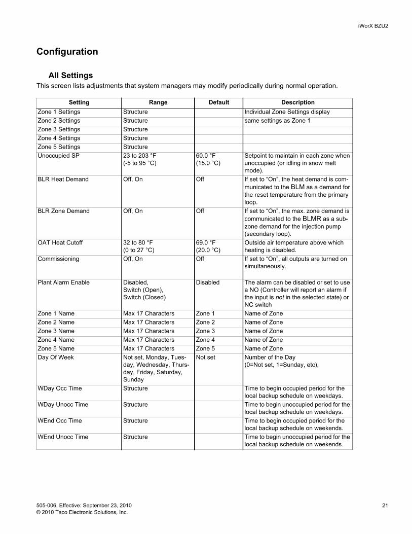
All SettingsThis screen lists adjustments that system managers may modify periodically during normal operation.
Setting Range Default DescriptionZone 1 Settings Structure Individual Zone Settings displayZone 2 Settings Structure same settings as Zone 1Zone 3 Settings StructureZone 4 Settings StructureZone 5 Settings StructureUnoccupied SP 23 to 203 °F
(-5 to 95 °C)60.0 °F (15.0 °C)
Setpoint to maintain in each zone when unoccupied (or idling in snow melt mode).
BLR Heat Demand Off, On Off If set to “On”, the heat demand is com-municated to the BLM as a demand for the reset temperature from the primary loop.
BLR Zone Demand Off, On Off If set to “On”, the max. zone demand is communicated to the BLMR as a sub-zone demand for the injection pump (secondary loop).
OAT Heat Cutoff 32 to 80 °F (0 to 27 °C)
69.0 °F (20.0 °C)
Outside air temperature above which heating is disabled.
Commissioning Off, On Off If set to “On”, all outputs are turned on simultaneously.
Plant Alarm Enable Disabled, Switch (Open), Switch (Closed)
Disabled The alarm can be disabled or set to use a NO (Controller will report an alarm if the input is not in the selected state) or NC switch
Zone 1 Name Max 17 Characters Zone 1 Name of Zone Zone 2 Name Max 17 Characters Zone 2 Name of Zone Zone 3 Name Max 17 Characters Zone 3 Name of Zone Zone 4 Name Max 17 Characters Zone 4 Name of Zone Zone 5 Name Max 17 Characters Zone 5 Name of Zone Day Of Week Not set, Monday, Tues-
day, Wednesday, Thurs-day, Friday, Saturday, Sunday
Not set Number of the Day(0=Not set, 1=Sunday, etc),
WDay Occ Time Structure Time to begin occupied period for the local backup schedule on weekdays.
WDay Unocc Time Structure Time to begin unoccupied period for the local backup schedule on weekdays.
WEnd Occ Time Structure Time to begin occupied period for the local backup schedule on weekends.
WEnd Unocc Time Structure Time to begin unoccupied period for the local backup schedule on weekends.

iWorX BZU2
22 505-006, Effective: September 23, 2010 © 2010 Taco Electronic Solutions, Inc.
Zone 1 - 5 Settings
Backup Occ Time / Backup Unocc Time for weekdays and weekend
Alarms
* When the controller enters from Unoccupied to Occupied state the alarm gets delayed for 30 min, to give the space some time to heat up.
Setting Range Default DescriptionZone Ovrid No,Yes No If set to “Yes”, heating is enabled for
that zone at the occupied setpoint, regardless of outside air temperature or occupancy status.
Zone Occ SP 32 to 203 °F(0 to 95 °C) 69.0 °F(20.0 °C) Setpoint to maintain in each zone when occupied (or when there is a snow melt demand)
Zone Offset +/- 99 °F(55 °C) 0.0 °F(0.0 °C) Number of degrees to add to each tem-perature reading.
Kp 0 to 20% 10.0% Gain used in the P+I loop that controls the output for zone 1.
Ki (min) 0 to 1000 min 10 min Response time of the Integral function for zone 1.
Stat Type Precon II,Precon III,Not used
Precon III Thermistor type, used in Wall mount or reference location
Setting Range Default DescriptionHours 0-23 0 Military time for the hour of the day
when the occupied or unoccupied state starts
Minutes 0-59 0 Minute, when occupied or unoccupied state starts
Alarm Range Alarm Trigger Alarm ResetTemperature Sensor Alarm Normal, Alarm Any one of the attached Sensors
is Open or ShortSensor Reading is within the specified Sensor range or faulty sensor gets replaced
Space Temperature Alarm Normal, Alarm Any one of the Zone Temperature readings is:above Space Occ Setp +1.5°F or below Space Unocc Setp -1.5°F
The Zone Temperature reading of the Zone in Alarm is:below Space Occ Setp -1.5°F orabove Space Unocc Setp +1.5°F *
Plant Alarm Normal, Alarm The contact for the Plant Alarm Input closes
The contact for the Plant Alarm Input opens
iWorX BZU2
505-006, Effective: September 23, 2010 23 © 2010 Taco Electronic Solutions, Inc.
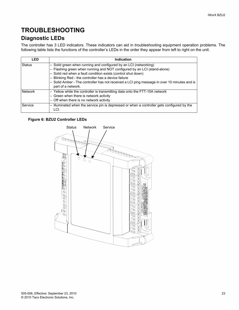
TROUBLESHOOTINGDiagnostic LEDsThe controller has 3 LED indicators. These indicators can aid in troubleshooting equipment operation problems. The following table lists the functions of the controller’s LEDs in the order they appear from left to right on the unit.
Figure 6: BZU2 Controller LEDs
Status Network Service
LED IndicationStatus – Solid green when running and configured by an LCI (networking)
– Flashing green when running and NOT configured by an LCI (stand-alone)– Solid red when a fault condition exists (control shut down)– Blinking Red - the controller has a device failure– Solid Amber - The controller has not received a LCI ping message in over 10 minutes and is
part of a network.Network – Yellow while the controller is transmitting data onto the FTT-10A network
– Green when there is network activity– Off when there is no network activity
Service – Illuminated when the service pin is depressed or when a controller gets configured by the LCI.

iWorX BZU2
24 505-006, Effective: September 23, 2010 © 2010 Taco Electronic Solutions, Inc.
Troubleshooting Tips
Getting HelpComponents within iWorX BZU2 controller cannot be field repaired. If there is a problem with a controller, follow the steps below before contacting your local TES representative or TES technical service.
1.Make sure controllers are connected and communicating to desired devices.2.Record precise hardware setup indicating the following:
Version numbers of applications software.
Controller firmware version number.
A complete description of difficulties encountered.
Problem SolutionController is not running and Status LED is not illuminated.
No power to controller. Verify the voltage on the controller’s power connector (24 VAC).
How do I reset the controller? The controller can be reset by the LCI, or you can cycle power to the controller. Refer to the LCI documentation for more information on resetting the controller using the LCI.
A zone pilot relay will not come on even though the LCI indicates it is on.
Ensure that the controller and output pilot relay have been powered with 24 VAC and the output has been correctly wired to the coil of the pilot relay. Also ensure that the pilot relay has a 24 VAC coil. Ensure that the output jumpers are in the right position for this application (isolated group, power sourcing or power sinking).
The 10K thermistor reading is out of range.
The input is either shorted or open.
Thermistor readings fluctuate rapidly, sometimes by several degrees.
The controller is not properly grounded. The controller’s ground (GND) pin (T40) must be connected to earth ground.Also ensure that the controller’s digital inputs are dry contacts and that no volt-age is being applied or switched to the inputs.
Controller is not running and Status LED is not illuminated.
No power to controller. Verify the voltage on the controller’s power connector (24 VAC).
Why is my pump short cycling? Ensure that the temperatures are properly grounded and that the PI Parameters are set properly. Kp should be between 5-10% and Ki should be set between 5-10Min.
Why is my space cold in the morning? The setpoint is at 70 °F but the room is still at the Unoccupied Temperature.
When a radiant zone enters the occupied mode after a night setback, the room needs to heat up and this takes longer than a conventional forced air heating. To avoid situations like that, schedule your occupied time 30 min (or the desired warm-up time for your individual situation) before you get up or expect the tem-perature to have reached the comfort point.

iWorX BZU2
Printed in the USA iWorX® and iView® are registered trademarks of Taco Electronic Solutions, Inc. © 2010 Taco Electronic Solutions, Inc. LON, LONWORKS, & LONMARK are trademarks of Echelon Corporation
CONTROLS MADE EASY®
Taco Electronic Solutions, Inc., 1160 Cranston Street, Cranston, RI 02920 Telephone: (401) 942-8000 FAX: (401) 942-2360.
Taco (Canada), Ltd., 8450 Lawson Road, Unit #3, Milton, Ontario L9T 0J8. Telephone: 905/564-9422. FAX: 905/564-9436.
Taco Electronic Solutions, Inc. is a subsidiary of Taco, Inc. Visit our web site at: http://www.taco-hvac.com
Taco Electronic Solutions, Inc. (TES) will repair or replace without charge (at the company's option) any product or part which is proven defective under normal use within one (1) year from the date of start-up or one (1) year and six (6) months from date of shipment (whichever occurs first).
In order to obtain service under this warranty, it is the responsibility of the purchaser to promptly notify the local TES stocking distribu-tor or TES in writing and promptly deliver the subject product or part, delivery prepaid, to the stocking distributor. For assistance on war-ranty returns, the purchaser may either contact the local TES stocking distributor or TES. If the subject product or part contains no defect as covered in this warranty, the purchaser will be billed for parts and labor charges in effect at time of factory examination and repair.
Any TES product or part not installed or oper-ated in conformity with TES instructions or which has been subject to accident, disaster, neglect, misuse, misapplication, inadequate operating environment, repair, attempted repair, modification or alteration, or other abuse, will not be covered by this warranty.
TES products are not intended for use to sup-port fire suppression systems, life support sys-tems, critical care applications, commercial aviation, nuclear facilities or any other applica-tions where product failure could lead to injury to person, loss of life, or catastrophic property damage and should not be sold for such pur-poses.
If in doubt as to whether a particular product is suitable for use with a TES product or part, or for any application restrictions, consult the applicable TES instruction sheets or in the U.S. contact TES at 401-942-8000 and in Canada contact Taco (Canada) Limited at 905-564-9422.
TES reserves the right to provide replacement products and parts which are substantially simi-lar in design and functionally equivalent to the defective product or part. TES reserves the right to make changes in details of design, con-struction, or arrangement of materials of its products without notification.
TES OFFERS THIS WARRANTY IN LIEU OF ALL OTHER EXPRESS WARRANTIES. ANY WARRANTY IMPLIED BY LAW INCLUDING
WARRANTIES OF MERCHANTABILITY OR FITNESS IS IN EFFECT ONLY FOR THE DURATION OF THE EXPRESS WARRANTY SET FORTH IN THE FIRST PARAGRAPH ABOVE.
THE ABOVE WARRANTIES ARE IN LIEU OF ALL OTHER WARRANTIES, EXPRESS OR STATUTORY, OR ANY OTHER WARRANTY OBLIGATION ON THE PART OF TES.
TES WILL NOT BE LIABLE FOR ANY SPE-CIAL, INCIDENTAL, INDIRECT OR CONSE-QUENTIAL DAMAGES RESULTING FROM THE USE OF ITS PRODUCTS OR ANY INCI-DENTAL COSTS OF REMOVING OR REPLACING DEFECTIVE PRODUCTS.
This warranty gives the purchaser specific rights, and the purchaser may have other rights which vary from state to state. Some states do not allow limitations on how long an implied warranty lasts or on the exclusion of incidental or consequential damages, so these limitations or exclusions may not apply to you.
LIMITED WARRANTY STATEMENT
Notes: