self-cleaning turbidity sensor
TRANSCRIPT

00713589
Self-cleaning Turbidity Sensor
Safety PrecautionsPlease read this entire instruction sheet before operating this sensor. Pay particular attention to all danger and caution statements. Failure to do so could result in serious injury to the operator or damage to the sensor.
Do not use or install this sensor in any manner other than that which is specified in this instruction sheet.
Use of Hazard InformationIf multiple hazards exist, this instruction sheet will use the signal word (Danger, Caution, Note) corresponding to the greatest hazard.
DANGER—Indicates a potentially or imminently hazardous situation which, if not avoided, could result in death or serious injury.
CAUTION—Indicates a potentially hazardous situation that may result in minor or moderate injury or instrument damage.
NOTE—Information that requires special emphasis.
Precautionary LabelsRead all labels and tags attached to the instrument. Personal injury or damage to the instrument could occur if not observed.
IntroductionThe self-cleaning turbidity sensor offers higher accuracy turbidity measurements and a wiper mechanism to reduce the effects of fouling. The sensor is available as an option on the DataSonde 4a, 4X or MiniSonde 4a and requires a new circuit board assembly and software driver with revision 1.05 or higher. Contact Customer Service for more details on software and hardware upgrades for older equipment.
The sensor uses a nephelometric method based on ISO 7027 (International Standard, Second Edition 1990-04-15). The sensor measures the intensity of light scattered by particles in the water sample at 90° from an 880 nm light source. The readings are displayed as NTU. The sensor also uses electronic modulation/demodulation techniques to reject errors due to ambient light.
The sensor optics are located on the bottom of the sensor body (see Figure 1). The optical path extends approximately 25.4 mm (1 in.) from the bottom of the sensor to the bottom of the calibration cup (or sensor guard). The path must be free of obstructions that can cause errors in the turbidity readings.
An internal motor automatically wipes the optical face at the start of every measurement. A user-definable parameter makes a number of extra wipes before every measurement, in addition to the first automatic wipe.
This symbol, if noted on the instrument, references the instruction sheet for operational and/or safety information.
1

Self-cleaning Turbidity Sensor
Removing and Installing the WiperTo remove and install the wiper, refer to Figure 1 and the following steps.
CAUTIONOvertightening or manually rotating the wiper arm once fastened to the shaft may cause damage to the gearbox and void the warranty.
Removing the Wiper
1. Carefully loosen the set screw holding the wiper on the motor shaft and remove the wiper.
Installing the Wiper2. Place the wiper assembly on the shaft with the set screw aligned with the flat
on the wiping shaft.
3. Gently press the wiper arm down until the wiper arm hits the stop on the shaft. The wiper pad should be compressed to approximately one half the original thickness.
4. Tighten the set screw. It is important that the wiper arm body does not make contact with the probe face—only the pad should be in contact. A gap of 0.5 mm (0.02 in.) between the wiper arm and the optic surface is typical when a new pad is installed.
Figure 1 Self-cleaning Turbidity Sensor
1. Motor Shaft Flat Surface 3. Wiper Assembly 5. Sensor Body
2. Set Screw 4. Wiper Pad
2

Self-cleaning Turbidity Sensor
Configuring the Sensor for Additional Wiper Rotations
Note: The circulator will automatically turn off when the brush is in motion. Allow for additional circulator warm-up time to account for the duration it was disabled.
Configure the unit using Hydras 3 LT to match the expected field conditions.
A cleaning cycle is initiated when power is applied to the sensor or at the beginning of a logging run warm-up.
To set the number of rotations, use the following procedure.
1. Connect the multiprobe to a PC.
2. Start Hydras 3LT. Wait for Hydras 3LT to establish communications with the sensor. Click the OPERATE SONDE button.
3. Click on the Parameter Setup tab and select Turbidity [Rev].
4. Enter the number of rotations from 1–9. The default is set to one rotation. Note: Each rotation takes approximately 6 seconds. When entering the number of rotations do not
allow the cleaning cycle to exceed the logging warm-up time.
5. Click the SAVE SETTINGS button.
3
Self-cleaning Turbidity Sensor
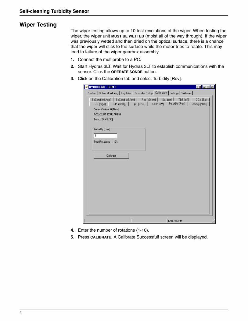
Wiper TestingThe wiper testing allows up to 10 test revolutions of the wiper. When testing the wiper, the wiper unit MUST BE WETTED (moist all of the way through). If the wiper was previously wetted and then dried on the optical surface, there is a chance that the wiper will stick to the surface while the motor tries to rotate. This may lead to failure of the wiper gearbox assembly.
1. Connect the multiprobe to a PC.
2. Start Hydras 3LT. Wait for Hydras 3LT to establish communications with the sensor. Click the OPERATE SONDE button.
3. Click on the Calibration tab and select Turbidity [Rev].
4. Enter the number of rotations (1-10).
5. Press CALIBRATE. A Calibrate Successful! screen will be displayed.
4

Self-cleaning Turbidity Sensor
Calibration Point SetupThe user can select between a 2-point and 4-point calibration.
2-point CalibrationFor standard applications, the NTU Calibration can use any 2-points between 0 and 3000 NTU to create a single zone of linear interpolation. Hach StableCal® standards of <0.1, 100, 1000, and 3000 NTU are available to create a linear interpolation zone as desired.
4-point CalibrationFor improved accuracy, the NTU Calibration can use any four points between 0 and 3000 NTU to create three zones of linear interpolation. Hach StablCal standards of <0.1, 100, 1000, and 3000 NTU are available to create linear interpolation zones from 0–100 NTU, 100–1000 NTU, and 1000–3000 NTU.
Calibrating the Sensor
Note: DO NOT SHAKE the StableCal solutions prior to calibration as this will introduce air bubbles which will impact the calibration.
Calibration can be performed in the calibration cup or in a stirred vessel. The latter is preferred for high turbidity standards.
1. Connect the multiprobe to a PC.
2. Start Hydras 3LT. Wait for Hydras 3LT to establish communications with the sensor. Click the OPERATE SONDE button.
3. Click on the Calibration Tab and select Turbidity NTU.
5

Self-cleaning Turbidity Sensor
4. Rinse the sensors and the calibration cup with turbid-free water (prepared by running distilled water through a 0.2 micron filter) several times and dry with a lint-free cloth or compressed air. Any residue or fluids left behind will affect the calibration accuracy.
Note: NTU readings may decrease as the solution settles. Be certain the solution has been sufficiently mixed by inverting gently as needed. Using a stir plate and stir bar is recommended for NTU values at or above 1000 NTU.
5. Remove the wiper from the unit. Store the removed wiper in turbid-free water for reinstallation.
6. Rinse the sensor end of the Sonde.
7. Fill the cup with StablCal standard, from 0 to 3000 NTU solution. To prevent excess bubbles, slowly pour the standard down the side of the cup.
8. Wait 30 seconds (minimum) for the NTU values to stabilize.
9. Enter the calibration point.
10. Enter the value of the turbidity standard and press CALIBRATE.
Note: For the “zero” point, Hach StablCal standard is listed at <0.1 NTU for controlled laboratory environments. Enter a value between 0.3–0.6 for the “zero” point, depending on the cleanliness of the environment and cup.
11. Rinse the calibration cup and the sensor twice with turbid-free water between each calibration point and dry with a lint-free cloth or compressed air. Any residue or fluids left behind will affect the calibration accuracy. Repeat until all points are calibrated as defined in the Calibration Point Setup on page 5.
12. After a successful calibration, "Calibration completed!" will be displayed. If "Calibration failed…" appears, then that point must be recalibrated.
13. Replace the wiper. See Removing and Installing the Wiper on page 2.
MaintenanceTurbidity sensor maintenance is required when any of the optical surfaces have a visible coating, or when a zero check using Hach StablCal <0.1 reads >0.9 NTU. To determine the maintenance frequency, monitor the rate and type of fouling and the deployment technique used at the deployment site. Often, post-deployment calibration checks will indicate a fouled sensor.
Required Items:
1. Remove the wiper. See Removing and Installing the Wiper on page 2.
2. Rinse the sensor with water directed at the lenses to remove any large caked deposits and loose residue. Use the brush to remove any additional residue such as sand or grit. Be careful not to scratch the optical surface. Use the brush to clean the wiper shaft.
3. Wet the cloth with non-abrasive soap and wipe the optical surface.
4. Rinse the sensor with deionized water until clean.
5. Replace the wetted wiper assembly. See Removing and Installing the Wiper on page 2.
• Deionized water • Non-abrasive soap• Clean, soft, nonabrasive, lint-free cloth • Small soft-bristle brush• Allen wrench
6

Self-cleaning Turbidity Sensor
SpecificationsSpecifications are subject to change without notice.
Accessories
Measurement Range Turbidity 0–3000 NTU
Resolution 0.1 NTU from 0–400 NTU, 1 NTU for >400 NTU
Accuracy* ±1% up to 100 NTU, ± 3% up to 100–400 NTU, ± 5% from 400–3000 NTU
Operating Temperature** –5 to 50 °C (23 to 120 °F)
Storage Temperature** –5 to 50 °C (23 to 120 °F)
Maximum Depth 225 m (738 ft)
* The following exceptions are taken to the specified accuracy under IEC 1000-4-3:1996: Vertically-oriented radiated interference of 10V/m between 150 and 900 MHz has been observed to cause measurement shifts up to 42 mV (with corresponding shifts in the turbidity reading) when the Sonde with this sensor was exposed to the stated field. Horizontally-oriented radiation interferences of 10V/m between 250 and 900 MHz has been observed to cause measurement shifts up to 7mV (with corresponding shifts in the turbidity reading) when the Sonde with this sensor was exposed to the stated field. Radiated interference testing was performed in air. Normal operation of the Sonde under water is expected to decrease the impact of the radiation interference.
** Non-freezing conditions
Description Catalog Number
<0.1NTU StablCal Standard, 500 mL 26597-49
20 NTU StablCal Standard, 500 mL 26601-49
40 NTU StablCal Standard, 1000 mL 27463-53
100 NTU StablCal Standard, 500 mL 26602-49
1000 NTU StablCal Standard, 500 mL 26606-49
3000 NTU StablCal Standard, 500 mL 28590-49
Allen Wrench 21324L
Replacement Wiper 007134
Wiper Kit (includes 4 replacement wipes and 1 Allen wrench) 007135
7

© Hach Company, 2004. All rights reserved. Printed in the U.S.A. eac/dk 07/04 3ed