selection of a future geothermal … current national n370 rig is a mechanical rig wh ere the power...
TRANSCRIPT
GEOTHERMAL TRAINING PROGRAMME Reports 2000Orkustofnun, Grensásvegur 9, Number 14IS-108 Reykjavík, Iceland
285
SELECTION OF A FUTUREGEOTHERMAL DRILLING RIG FOR KENYA
Eustace Githaiga NdiranguKenya Electricity Generating Co Ltd,
Olkaria Geothermal Project,P. O. Box 785, Naivasha,
ABSTRACT
The main objective of this report is to determine the technical specifications of a futuregeothermal drilling rig for Kenya. Analysis is made as a guide in the selection of theprincipal components of a geothermal drilling rig. It is planned that both vertical anddirectional wells with a 3000 m and 2500 m depth limit, respectively, will be drilled.International requests for information were floated to reputable rig manufacturers forcomparison purposes to obtain their recommendations. The results obtained showedthat a mast with a hook-load of 200 tons would suffice and optimum power inputrequired to the mud pumps, rotary table (top drive) and drawworks is 746 kW ofpower each. A three diesel engine-generator set with a total output capacity of around1.8 MW of electric power is sufficient for the planned drilling programme.
1. INTRODUCTION
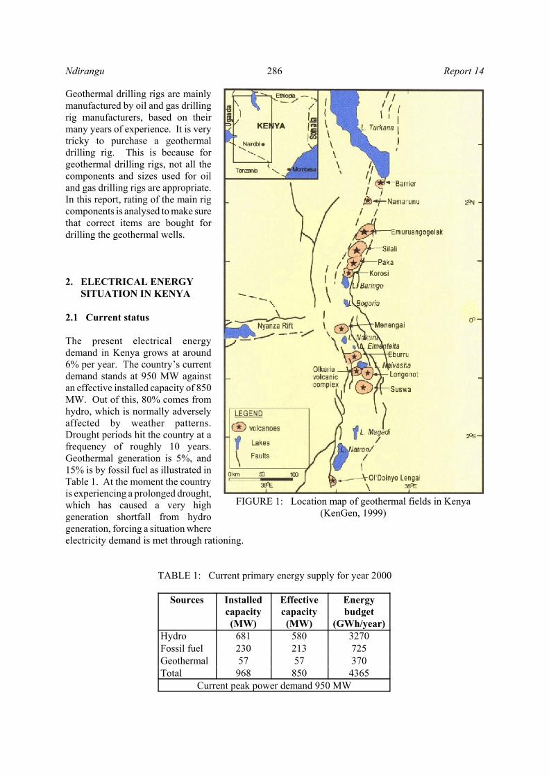
Kenya is one of the developing countries situated in East Africa. The government has set a goal for thecountry to become industrialized by the year 2020. In order to achieve this goal, the energy sector needsto expand very fast to supply additional energy to new industries. The country has renewable energysources such as hydro, geothermal, solar and wind but imports non-renewable fossil fuels for itstransportation sector and for a part of the electricity generation. Kenya has vast geothermal resources; thelargest known geothermal fields are illustrated in Figure 1. From Olkaria and other geothermal resources,576 MW of electrical power is expected to be developed over the next 17 years, through private and publicinvestments.
So far, scientific studies and exploration work have been carried out on the Longonot and Suswageothermal prospects. Drilling in three phases has yet to be done in these two fields; exploratory drillingto delineate the resource, appraisal drilling to prove the resource, and finally production drilling.Currently, Kenya Electricity Generating Company Ltd. (KenGen), which is responsible for the geothermalresource assessment programme (GRAP), owns and operates only one old National Oilwell N370mechanical rig. This rig is not able to keep the pace of developing 576 MW of electric power in the next17 years. As a result, a new rig purchase is planned to make the geothermal energy generation expansionfeasible.
286Ndirangu Report 14
FIGURE 1: Location map of geothermal fields in Kenya(KenGen, 1999)
Geothermal drilling rigs are mainlymanufactured by oil and gas drillingrig manufacturers, based on theirmany years of experience. It is verytricky to purchase a geothermaldrilling rig. This is because forgeothermal drilling rigs, not all thecomponents and sizes used for oiland gas drilling rigs are appropriate.In this report, rating of the main rigcomponents is analysed to make surethat correct items are bought fordrilling the geothermal wells.
2. ELECTRICAL ENERGY SITUATION IN KENYA
2.1 Current status
The present electrical energydemand in Kenya grows at around6% per year. The country’s currentdemand stands at 950 MW againstan effective installed capacity of 850MW. Out of this, 80% comes fromhydro, which is normally adverselyaffected by weather patterns.Drought periods hit the country at afrequency of roughly 10 years.Geothermal generation is 5%, and15% is by fossil fuel as illustrated inTable 1. At the moment the countryis experiencing a prolonged drought,which has caused a very highgeneration shortfall from hydrogeneration, forcing a situation whereelectricity demand is met through rationing.
TABLE 1: Current primary energy supply for year 2000
Sources Installedcapacity(MW)
Effectivecapacity(MW)
Energybudget
(GWh/year)Hydro 681 580 3270Fossil fuel 230 213 725Geothermal 57 57 370Total 968 850 4365
Current peak power demand 950 MW

287Report 14 Ndirangu
It is estimated that the demand for electrical energy will almost triple if the average of 6% growth rate peryear is maintained for the next 17 years. In order to sustain this rapid growth, plans are under way toexpand generation facilities to cope with the increase in demand. According to government plans, anadditional 313 MW is expected to be generated from hydro, 576 MW from geothermal resources, 762 MWfrom medium speed diesel and 250 MW from low speed diesel. This generation expansion plan isestimated to cost about USD 3.35 billion, a huge amount of money, which is expected to come from thegovernment and private sector. Over the next 5 years, it is expected that 271.5 MW of additional capacitywill be constructed with public sector financing and 249 MW by independent power producers (Mwangi,2000).
Out of the planned 576 MW to be developed from geothermal resources, half is expected to be developedby the public sector and the rest by the private sector. In order to achieve this goal, detailed scientificstudies and exploration drilling are required in several geothermal prospects outside Olkaria in order toprove the resource and prioritize the areas. Scientific exploration work has been done in Longonot andSuswa prospects and exploration drilling is planned to follow. Surface exploration will then be done inMenengai and other fields to the north of Olkaria along the Rift Valley. Experience has shown thatproduction drilling may have to be done by the government for 30-50% of the required steam to reduceinvestment risks before the private sector is interested in further development. Kenya has enormousgeothermal energy potential, which is underdeveloped. The potential for geothermal energy for electricityproduction is by scientific methods (Ng'ang'a, 1998) estimated to be around 2000 MW, but only 57 MWare now being generated. Currently 45 MW are coming from the Olkaria I power plant of KenGen, and12 MW from the Olkaria III power plant, which is still under construction by an independent powerproducer (Orpower 4 Inc.). It will generate up to 64 MW when it is completed. The Olkaria II powerplant, whose construction has also been started by KenGen, will generate up to 64 MW once completed.
2.2 Future geothermal energy expansion
The 1998 National power development plan update calls for additional 576 MW of geothermal power bythe year 2017. The plan assumes that seven 64 MW power plants will be built. The process of developinga geothermal resource involves exploration, appraisal drilling, production drilling and power plantconstruction. An average of 34 MW of geothermal power will have to be developed every year. Theaverage electrical generation potential from a geothermal well in Kenya has historically been around 3MW per well. This means that in order to meet the current National power development plan, at least 12production wells must be drilled every year over a period of 17 years. The current N370 drilling rig is notable to drill this number of wells per year and a new rig is thus urgently needed. Well trained manpoweris available in Kenya today to operate the two rigs.
3. CASING PROGRAMME
The well’s casing programme is prepared in compliance with the practice codes for deep geothermal wellswhich includes casing strings and liners (New Zealand Standard No 2403, 1991). This requires casingto prevent the hole from collapsing, to support drilling and permanent wellheads, to contain well fluids,to control contamination of subsurface aquifers, to counter circulation losses during drilling, and to protectthe integrity of the well against corrosion, erosion or fracturing. Casing strings and liners for typical wellsare illustrated in Figure 2. The following description is for the Case 1 (Figure 2) well.
Surface casing: The 26" diameter hole is drilled to 60 m, the hole cased with 20" × 94 lb/ft casing andcemented back to surface. The drilling fluid is water-based bentonite mud, or water in case of loss ofreturn circulation.

288Ndirangu Report 14
FIGURE 2: Casing programme of geothermal wells in Kenya
Anchor casing: The 17 ½”diameter hole is drilled to adepth between 250 and 400m. The hole is cased back tothe surface with 13 d” × 54.5lb/ft K55 buttress thread(BTC) steel casing, andcemented back to the surface.The drilling fluid is waterbased bentonite mud. Wateror stiff foam will be used incase of severe loss of returncirculation.
Production: The 12 ¼” dia-meter hole is drilled to a depthbetween 600 and 1200 m.The hole is cased back to thesurface with 9 e” × 40 lb/ftK55 buttress thread (BTC)steel casing and cementedback to the surface. Thedrilling fluid is mud, water,stiff foam, or aerated mud orwater.
Open hole: The 8½” diameterhole is drilled to a maximumdepth of 3000 m for verticalwells and 2500 m fordirectional wells. The hole islined with 7” × 26 lb/ft K55buttress thread (BTC) steelslotted casing extending upfrom the well bottom past the9 e” casing shoe, with anoverlap of about 28-30 m.The drilling fluid is aeratedwater.
4. DRILLING FACILITY UPDATE
4.1 History of drilling in Kenya
In 1976 the then East African Power and Lighting Company Limited bought the first rig, called T12. Thiswas largely in view of the high capital costs involved in harnessing hydropower. The drilling section ofKenGen, then known as Kenya Power Company (KPC), expanded with the purchase of the second rig

289Report 14 Ndirangu
E
G
X
SCR
X
RT
SCR
X
DW
SCR
X
MP
SCR
X
E
G
X
E
G
X
Diesel CAT Engines
AC Generators 750KVAThree phase 0.8 P.F.
600/415/240VACStepdown TX
600VAC BUS BAR
M PAuxiliary loads
Prim e m overs
Bus bar
FIGURE 3: Single line diagram of a diesel-electric system
(N370) in 1980. Both T12 and N370 drilled the production wells for the 3 × 15 MW Olkaria geothermalpower plants where the first unit was commissioned in 1981 and the other two in 1982 and 1985,respectively. The N370 rig still in service has aged, completing its economical life in 1995, but the T12rig was retired and scrapped. To keep the facility alive for KenGen’s future use and to lower costscompared with contracting services, KenGen is considering purchasing a new and modern rig.
4.2 Current drilling rig
The current National N370 rig is a mechanical rig where the power to major rig components such as therotary table, drawworks and mud pumps is provided through a mechanical power transmission. Thediesel engines are located close to the load centres to be driven and belts, pulleys, and chains transmit thepower, and sprockets send engine power to various parts of the rig. On a mechanical rig, the compoundtransfers and directs the power of the engine. A compound consists of several sprockets and chains. Eachengine drives a set of these heavy-duty sprockets. The engine sprockets turn a set of chains runningbetween each engine. Additional sets of chains and sprockets in the compound transfer the power to therotary table and drawworks.
4.3 Future drilling rig
There are three different types of rigs on the market today; mechanical, electric and fully hydraulicallyoperated rigs. KenGenintends to procure adiesel-electric rig as itsfuture geothermal drillingrig. An electric rig doesnot require chains andsprockets to transferpower. Most new rigstoday on the market areelectric, because theyallow variable speedoperation and goodcontrol and are easier torig up and maintain thanthe mechanical rigs. Onan electrical rig, eachdiesel prime mover hasan electric generatorconnected directly to it.Cables then conduct theelectricity to the electricmotors as illustrated inFigure 3. Each electricmotor is attached directlyto the equipment thatrequires power, such asthe drawworks, the rotarytable or the top drive, andthe mud pumps and theDC motors are controlledby a silicon controlledrectifier (SCR) system.
290Ndirangu Report 14
5. RIG SIZE SPECIFICATIONS
5.1 Factors affecting rig selection
The depth a rig is capable of attaining is of major concern to the owner when deciding on a drillingprogramme. The casing programme affects the rotary table size, hoisting requirements and pump capacityto clean the hole. Exploratory drilling or slim holes versus large diameter casings for production wells,must be decided. The main factors affecting the rig selection are: (L’Espoir, 1984)
• Mast total gross capacity;• Hook load of mast and drawworks;• Capacity and pressure rating of rig pumps and power;• Size of hole in the rotary table to handle large diameters;• Height of substructure to accommodate BOP stack;• Size of drill pipe (4½” or 5”).
Other factors to be analysed when determining a suitable drilling rig include location of the well and rigsize (layout). Economics also come into play.
5.2 Requirements for high-temperature geothermal drilling
Geothermal drilling rig equipment and technology are based for the most part on the many years ofexperience of oil and gas exploration and production drilling. There are very few manufacturersspecialising in building geothermal drilling rigs. In light of this, it is important to understand what isspecial about geothermal drilling even before calculating and selecting the major rig components. Themain things to take note of are (Thórhallsson, 2000):
• Downhole temperatures of 200-350/C;• Pressure gradient hydrostatic or less;• Drilling in igneous rock, basalt to acidic rocks (high in silica);• Danger of steam blowouts;• Zones with large or total circulation losses;• Poor hole condition-collapses, stuck drill pipe;• Special material for construction e.g. steel grades, high-temperature cements;• Open holes for long sections with slotted liners, e.g. 700-2200 metres;• Production through casing, no tubing strings;• Simple drilling muds, water or aerated fluids used for drilling;• Air used to drill under-pressured vapour-dominated reservoirs;• No fire or explosion hazard;• Low pollution.
The above factors affect the selection of the most desirable components for a geothermal drilling rig whenit is being bought from gas and oil rig manufacturers.
5.3 Determination of mast capacity
The individual components of the rig must be balanced so that each unit performs its allotted taskefficiently. For example, a rig would not be properly balanced if the power plant was large enough to drill5000 m yet the mast could handle only 2000 m. The mast is the most critical component of the rig thatdetermines the rig’s depth limit (McCray and Cole, 1959). The travelling block exerts the hook loadweight on the crown block. The force (weight) exerted on the crown block is then distributed equally ontothe rig mast. The mast should, therefore, be properly designed to carry the largest dry weight of the

291Report 14 Ndirangu
Im aginary cut
Dead
line
C rown Block
Travelling Block
Hook
Fast line
W inch
FIGURE 4: Rotary drilling line string-up on the crownand travelling blocks
drilling string and casing loads exerted on it by these two major loads, plus an allowance for fishingoperations. Tables 2, 3 and 4 illustrate the possible dry weights exerted on the travelling block by thedrilling string and casing to drill 2200 m and 3000 m deep geothermal wells described in Chapter 3.
TABLE 2: Total dry weight of drilling to 2200 m, for Case 1 of the casing programme
Item Description Size (“) (lb/ft) (kg/m)
Depth(m)
Total weight(tons)
1 Surface casing 20 94 140 60 8.42 Anchor casing 13 d 54.5 81 260 21.13 Production casing 9 e 40 60 700 41.74 Slotted liner 7 26 39 1500 58.05 Drilling string / 20 tons drill collar 5 19.5 29 2200 83.8
TABLE 3: Total dry weight of drilling to 2200 m, for Case 2 of the casing programme
Item Description Size (“) (lb/ft) (kg/m)
Depth(m)
Total weight(tons)
1 Surface casing 22 ½ 117 174 60 10.52 Anchor casing 18 e 87.5 130 260 33.93 Production casing 13 d 54.5 81 700 56.84 Slotted liner 9 e 40 60 1500 89.35 Drilling string / 20 tons drill collar 5 19.5 29 2200 83.8
TABLE 4: Total dry weight of drilling to 3000 m, for Case 1 of the casing programme
Item Description Size (“) (lb/ft) (kg/m)
Depth(m)
Total weight(tons)
1 Surface casing 20 94 140 60 8.42 Anchor casing 13 d 54.5 81 300 24.33 Production casing 9 e 40 60 1000 59.54 Slotted liner 7 26 39 2000 77.45 Drilling string / 20 tons drill collar 5 19.5 29 3000 107.1
In order to determine themaximum load imposed on themast (gross load rating of themast) by the crown block, (seeillustration in Figure 4) the mastis cut in half between the crownblock and travelling block by animaginary line. Double arrowssymbolize the number of linespulling down the crown blockwhile the number of lines pullingup on the travelling block aresymbolized by single arrows.Therefore, the maximum grossload divided by the number oflines pulling down will dictatethe maximum allowable single

292Ndirangu Report 14
FIGURE 5: A convectional drilling rig
line pull. The load inthe wireline, expressedin tons of tension, isconstant in the linefrom the drum to thedead line anchor.Thus, the usablem a x i m u m s t a t i chookload for Figure 4is the number of linespulling up on thet r a v e l l i n g b l o c kmultiplied by the singleline pull.
The total dry weight ofthe entire drillstringshould not exceed 75%of the static hookloadrating. This allows areserve pulling capacityof 25% in a dry hole.For drilling directionalwells, an overpull of50-100 tons should beavailable.
5.4 Hoisting system
The hoisting systemc o n s i s t s o f t h edrawworks, the derrick(mast), the crownblock, the travellingblock, and wire roped r i l l i n g l i n e a sillustrated in Figure 5.On a hydraulic rig thehoisting is by means ofa hydraulic cylinder.The function of thehoisting equipment isto get the necessaryequipment in and out ofthe hole as rapidly as iseconomically possible.The principal items ofequipment that are usedin the hole are thedrilling string, casing,
and miscella-neous well surveying instruments such as logging and hole-deviation instruments. Thedrilling string is one of the most important considerations in the design of the hoisting equipment,although casing loads and fishing operations may be the largest loads imposed on the derrick. During adrilling operation, the drill bit becomes worn at frequent intervals, necessitating its removal and

293Report 14 Ndirangu
(1)
GardnerDenver
PZ8
GardnerDenver
PZ8
GardnerDenver
FXN
To kill line
To the we ll
Shaleshaker
MagflowPt100
C utting p lus flu id from the we ll
W ater
W aste waterpond
To PC logger
To PC logge r W aterpump
Mudmixing
Mudmixingpump30 kW
C emen t slu rryto the w ell
To cemen tingpump
To cement mixe r
M ud tanks
FIGURE 6: A schematic diagram of a fluid circulation system
replacement, which requires removal of the entire drill string.
The drawworks is one of the largest and heaviest pieces of equipment on a rig. It has a spool-shapedrevolving drum around which the drilling line is wrapped. It has several shafts, clutches, brakes, andchain-and-gear drives. The motor and clutch are the main factors in determining the maximum single linepull of the drawworks. The brakes are usually matched to the single line pull. The load and the pullingspeed determine the mechanical power expended.
The power for the drawworks is obtained by the following equation (Gabolde and Nguyen, 1999):
where P = Power in kilowatts (kW);M = Mass (tons);v = Hoisting velocity (m/s);n = Transmission efficiency.
5.5 Fluid circulation system
The drilling fluid circulates through many pieces of equipment, including the mud pump, the standpipe,the rotary hose, the swivel, the kelly (or the top drive), the drill pipe, the drill collars, the bit, the annulus,the return line, the shale shaker, and the mud tank, as shown in the fluid circulation system componentillustration in Figure 6.
The mud pumps draw in the drilling fluid through the suction line from the mud tanks and send it outthrough the discharge line and to the rest of the fluid circulation system. Prior to equipment evaluationand selection, drilling fluids and hydraulics programmes are prepared. The programme considers at leastthe following aspects for every stage of drilling:
294Ndirangu Report 14
(2)
(3)
(4)
• The type of drilling fluid to be used and its properties;• Minimum annular velocities necessary to ensure adequate removal of cuttings from the well;• Pressure losses through each component of the circulation system;• The need for a cooling tower;• Ability to cool and quench the well.
5.6 Determination of mud pump capacity, pressure and power
The mud pump is a very critical piece of equipment of the principal drilling rig components. It pumps thedrilling fluids through the circulation system. Incorrect selection of the mud pump in terms of its capacityand pressure ratings can make achieving the desired well depth target very difficult. Therefore, selectionof the correct mud pump to match a particular drilling programme is very important. Geothermal wellsare of large diameter and drilled with water which requires relatively large pumps. In order to determinethe capacity (l/s) and pressure (bar) parameters of the mud pumps, the drilling programme must be known.This includes hole diameter, hole depth, diameter and style of drill-pipe, drilling fluids, and all relatedequipment. For drilling with a down-hole motor, the driving power is derived from the drilling fluid (extrapressure loss).
The pump discharge capacity must be enough to obtain an annular upflow velocity sufficient to removeall the cuttings from the borehole. The required pump flowrate (Q, l/s) is calculated based on the annularvolumes and required upflow velocity (Ton, 1997).
where Vh = Volume of the well (l/m);Vp = Volume of drill pipe (l/m);v = Annular velocity (m/s).
Knowing the flowrate (Q, l/s) the individual pressure drops are calculated from friction loss curves of thesurface equipment, the drill pipe and drill collars, and the drill bit. The total pressure losses (p, bar) areobtained by summing up the individual losses. The pump pressure rating must be more than 1.5 times thetotal pressure losses. These pressure losses are comprised of
where p1 = Losses through surface equipment;p2 = Losses through drill pipe/drill collars;p3 = Losses through the rock bit;p4 = Losses between the outer diameter of the drill pipe and drill collar, and wall of the hole;p5 = Losses in the mud motor (when used, e.g. directional drilling).
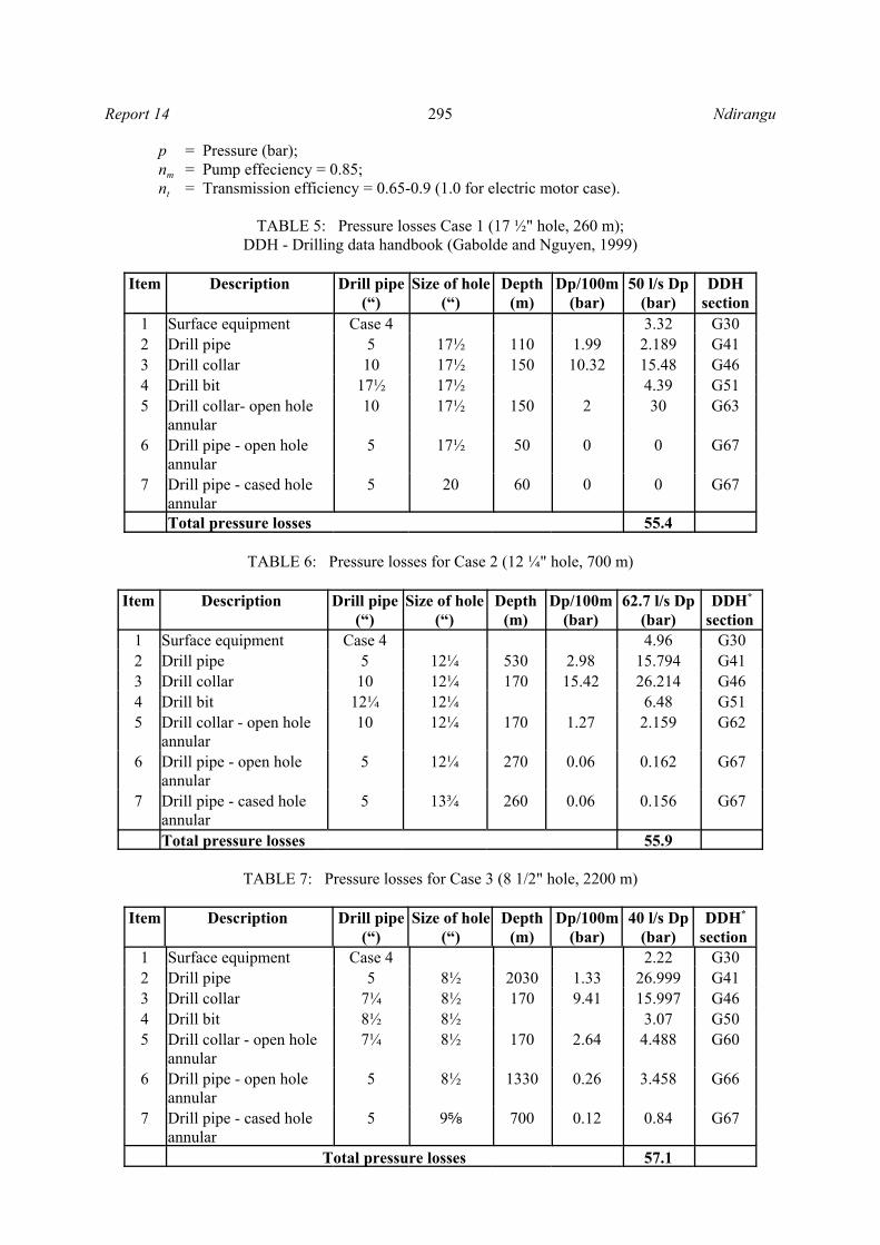
Tables 5, 6 and 7 list the various values of pressure losses when drilling the 17 ½”, 12 ¼” and 8 ½” holesat the respective flow rates. Once the correct pump flowrate values (Q, l/s) and the total pressure losses(p,bars) are known, then the power of the mud pump can be calculated by applying Equation 4 (Gaboldeand Nguyen, 1999).
where P = Mud pump power (kW);Q = Flow rate (l/s);
295Report 14 Ndirangu
p = Pressure (bar);nm = Pump effeciency = 0.85;nt = Transmission efficiency = 0.65-0.9 (1.0 for electric motor case).
TABLE 5: Pressure losses Case 1 (17 ½" hole, 260 m);DDH - Drilling data handbook (Gabolde and Nguyen, 1999)
Item Description Drill pipe(“)
Size of hole(“)
Depth(m)
Dp/100m(bar)
50 l/s Dp(bar)
DDHsection
1 Surface equipment Case 4 3.32 G302 Drill pipe 5 17½ 110 1.99 2.189 G413 Drill collar 10 17½ 150 10.32 15.48 G464 Drill bit 17½ 17½ 4.39 G515 Drill collar- open hole
annular10 17½ 150 2 30 G63
6 Drill pipe - open holeannular
5 17½ 50 0 0 G67
7 Drill pipe - cased holeannular
5 20 60 0 0 G67
Total pressure losses 55.4
TABLE 6: Pressure losses for Case 2 (12 ¼" hole, 700 m)
Item Description Drill pipe(“)
Size of hole(“)
Depth(m)
Dp/100m(bar)
62.7 l/s Dp(bar)
DDH*
section 1 Surface equipment Case 4 4.96 G302 Drill pipe 5 12¼ 530 2.98 15.794 G413 Drill collar 10 12¼ 170 15.42 26.214 G464 Drill bit 12¼ 12¼ 6.48 G515 Drill collar - open hole
annular10 12¼ 170 1.27 2.159 G62
6 Drill pipe - open holeannular
5 12¼ 270 0.06 0.162 G67
7 Drill pipe - cased holeannular
5 13¾ 260 0.06 0.156 G67
Total pressure losses 55.9
TABLE 7: Pressure losses for Case 3 (8 1/2" hole, 2200 m)
Item Description Drill pipe(“)
Size of hole(“)
Depth(m)
Dp/100m(bar)
40 l/s Dp(bar)
DDH*
section 1 Surface equipment Case 4 2.22 G302 Drill pipe 5 8½ 2030 1.33 26.999 G413 Drill collar 7¼ 8½ 170 9.41 15.997 G464 Drill bit 8½ 8½ 3.07 G505 Drill collar - open hole
annular7¼ 8½ 170 2.64 4.488 G60
6 Drill pipe - open holeannular
5 8½ 1330 0.26 3.458 G66
7 Drill pipe - cased holeannular
5 9e 700 0.12 0.84 G67
Total pressure losses 57.1

296Ndirangu Report 14
5.7 Air compressor
Selecting an air compressor is just as critical as selecting a mud pump. This is of major concern in drillingprogrammes where air and foam are to be used as drilling fluids. A minimum return air velocity of 15.0m/s is needed for proper hole cleaning while a return velocity of 25.0 m/s is considered good and willprevent the bit from crushing the same cuttings over and over again.
A proper air compressor can be chosen only when the reservoir pressure and the hole size and depth areprecisely known (Njee, 1986).
6. RIG POWER PLANTS
6.1 Determination of prime-mover ratings
The power plant is the heart of a drilling rig. The power developed by the rig power plant is usedprincipally for three operations: (McCray and Cole, 1959)
• Rotary table or top-drive system;• Hoisting;• Drilling fluid circulation.
In addition to these major functions, several auxiliary operations are powered by the rig power plant. Inorder to properly select the size of the rig prime mover, the power requirements of the hoisting, rotatingand mud pumps must be known. The size of all the main and auxiliary equipment, such as: mast, mudpumps, rotary table, transmission, crown block, travelling block, hook, mud cleaning and mixingequipment, light plants, etc., must match the rig power. The power plant should also have adequate powerfor directional drilling. This is because the steerable motor for directional drilling requires extra hydraulicpower from the pumping units.
6.2 Comparison of mechanical and electric power transmission rigs
A diesel-electric rig has several advantages over a mechanical rig. For one thing, a diesel-electric rigeliminates the heavy and complicated compound and chain drive. By eliminating the compound, the rig-up crew does not have to worry about getting the compound lined up with engines and the drawworks.Aligning the engines, the compound, and the driven components can be time consuming. What is more,in a diesel-electric drive, the crew can place the engines well away from the rig floor, because powercables that send electricity to the motors can be relatively long. Remote engine placement reduces noiseand vibration on the rig floor, thus making the drilling crew’s job a little more pleasant (Baker, 1996).
In a mechanical drive on the other hand, the engine must be fairly close to the components being driven.The mechanical elements of the compound are large and bulky and, unlike electric cable, cannot easilybe run long distances. Since the drawworks must be on or very near the rig floor, the engines in amechanical set-up must therefore also be near the rig floor.
6.3 Choice of electric motor for major power drives
On an electric rig all the power drives are provided by appropriate AC or DC electric motors. The choiceof a particular motor for use in a given drive depends on the torque-speed characteristics of the drive.There are two types of drives found on a modern electric rig. These are constant speed drives (CSD) andvariable speed drives (VSD). In both cases, the energy is supplied to the process through the motor shaft.Torque and speed are the only physical quantities that describe the state of the shaft. The rotary table (or
297Report 14 Ndirangu
the top drive), the drawworks and mud pumps require variable speed drive. This is because the flow ofenergy from the prime mover to these processes needs to be controlled. Very high torque at zero speedis at times required for these three principal processes. The GE 752 DC series and shunt traction motorsare, hence, well suited in such situations where high torque at low speeds is needed. Other drives, whichrequire a constant supply of energy to the process, use AC electric motors, e.g. mud mixers, centrifugalpumps (McNair, 1980).
6.4 Auxiliary systems
In addition to the three principal operations in drilling, circulating, rotating, and hoisting, severalmiscellaneous functions are performed which require power from the same source as the principaloperations. Careful consideration must be given to the placing of the auxiliary equipment in the powerarrangement or else adequate power may not be delivered to one of the principal operations when needed.Some of these miscellaneous functions are:
• Rig lighting system;• Shale shaker;• Mud mixer;• Water/mud transfer pumps;• Air compressors;• Air fans or blowers for the cooling SCR system;• Power for hydraulically operated BOP accumulator;• Power for rig shacks/offices (light, heating, cooking, air-conditioning).
An extra reserve power capacity must be taken into consideration when deciding on the overall rig’spower to cater to any additional miscellaneous power requirement in the future.
6.5 Rig instrumentation system
The rig instrumentation system provides real-time information to the driller and the geologist about theparameters of the well being drilled. Among the information that instruments provide on a drill rig are:
• Weight on bit (WOB);• Pump pressure (standpipe pressure);• Mud pump stroke per minute (SPM);• Revolution per minute (RPM) on rotary table;• Rate of penetration (ROP) / depth;• Temperature in (T1) and out (T2) of the circulating fluid;• Torque on the drill pipe;• Return flow of the fluid from the well;• PIT level.
This data is gathered for economic considerations and for safety of personnel and equipment. Eachinstrument provides data to improve drilling performance, reduce equipment wear, anticipate potentialwell blowouts and prevent overloads. This data is also very valuable for geological/reservoir data as itprovides information such as location of loss zones, etc. Each rig has all or some combinations ofelectrically operated instruments to record rig data.
On most rigs, the instruments are individually mounted and terminated to sensors located at the point ofmeasurement (see illustration in Figure 7). The sensor data is combined into a single readout dataacquisition logger. The output readouts from the data logger are connected to computer for online displayand saved on the server for future analysis and print out. Figure 8 illustrates a schematic of a data-loggersystem from the sensor to the computer with remote monitoring at the drilling headoffice.

298Ndirangu Report 14
RPM TEMP 1
PUMPPRESS
PUMP 2SPM
RETURNFLOW
PUMP 1SPM
KELLYPOS
TEMP 2
PCSERVER
LOGGER
CLIENTS
FIGURE 7: Drilling rig instrumentation system
8 LinesPC DATALOGGER
Comm unication link
Printer
Fieldcom puter
O fficecomputer
From fieldsignal sensors
To drillerconsole
FIGURE 8: Schematic diagram of a data-logger system
7. RIG SELECTION
7.1 Rig manufacturers contacted
Requests were sent to ten rigmanufacturers, out of whichfive responded positively.These five firms presentedrigs with different speci-fications based on theinformation provided aboutthe well design (Figure 2).Table 8 shows the comparisonof the major rig featuresoffered by these manu-facturers. The very detailedtechnical specificationsreceived covered 50-100pages. It is outside the scopeof this paper to analyse andcompare all the features. Thatis a part of the procurementprocess. No price informationwas requested for the samereason. The offers receivedby each of the manufacturersare briefly described below.

299Report 14 Ndirangu
TABLE 8: Comparison of rig features offered by the different manufacturers
Company name TESCOCorporation
National-Oilwell
CooperMan. Co.
CrownIndustries
BentecGmbh
Description Mast Depth capability 3000 m 3500 m 3500 m 3500 m 3500 mHeight 30.5 m 41.5 m 41.5 m 43.3 m 47.5 mGross nominal capacity - - 270 tons 381 tons 340 tonsStatic hook load 200 tons 230 tons 180 tons 272 tons 275 tonsTravelling block Max lines strung 8 10 8 10 10Rating of the assembly 200 tons 230 tons 265 tons 300 tons 350 tonsSwivel head Static capacity 250 tons - 250 tons 193 tons 272 tonsWorking pressure - - - 345 bar 310 barTop drive Yes Yes - Yes YesStatic loading 250 tons 250 tons - 350 tons -Max RPM 220 rpm 200 rpm - - -Substructure Nominal height 6.5 m 5.4 m 7.6 m 7.6 m 7.9 mSet back load 150 tons 136 tons 136 tons 181 tons 158 tonsTotal capacity 300 tons - 295 tons 272 tons 382 tonsDrawwork Max input power 746 kW - 746 kW 746 kW 820 kWRated capacity 250 tons - - 229 tons 230 tonsAuxiliary brake Yes Yes Yes Yes -Rotary equipment Opening size 27.5" 27.5" 27.5" 27.5" 27.5"Static loading 368 tons - 170 tonsMax RPM 200 rpm 210 rpmMud pumps Number of mud pumps 2 2 2 2 2Max input power 746 kW 969 kW 746 kW 1193 kW 746 kWMax working pressure 344 bar 400 bar 210 bar 345 bar 340 barMax flowrate 55 l/s 60 l/s 52 l/s - 43 l/sPower plantEngine-generator system 3 3 2 2Continuous power 600 kW 840 kW 1465 kW 1050 kWGen. Max. Power 634 kW - - -Gen. Output voltage 600 V 600 V 600 V 600 VGenerator frequency 50 Hz 50 Hz 60 Hz 50 HzMudtanks Numbers 2 6 2 4Capacity 60 m3 320 m3 - 190 m3 270 m3
Tesco Corporation. This company is offering a Tesco modular, all hydraulic, self elevating drilling rigrated at 3000 m with a 4½” drill pipe, with swing-up, and telescoping double mast. The rig is designedto move using pickers and convectional tractor-trailer units. Except for the substructure, mast package,pipe tubes and prime mover, all equipment is housed in standard shipping containers, which are typically2.44 m wide × 6.1 m long × 2.59 m high. The mast can accommodate a Tesco 250 tons top drive.

300Ndirangu Report 14
National Oilwell. This company is offering an IRI 1100 E series drilling rig consisting of model 2346SHL drawworks, Baylor 5032 assist brake, provisions for one GE 752 series wound electric motorsdriving into transmission and all mounted on a four axle rig trailer. The substructure is a hydraulictelescoping type. The mast is three section telescopic and will accommodate Bowen 250 tons top drive.Racking capacity is for 4½” drill pipes ranged in triplets. Other items include hydraulic catworks, utilityboom, pipe slide, back up posts, two BOP dollies and track system, a self-contained hydraulic power skidpackage, racking board, belly board, crown jib, and powered reserve line spool. The rig is also equippedwith a self-contained hydraulic power skid package on a single axle trailer. It has an independent electricrotary drive mounted in the substructure.
Cooper Manufacturing Corporation. This company is offering a Cooper 1000 HP electric desert trailer-drilling rig with self-elevating telescoping mast. The mast has a wind capacity of 85 miles per hour withpipe racked in and 120 miles per hour on a bare mast. The mast is with raising cylinders. The mast willalso include an adjustable racking board with a capacity of 110 stands triplets of 4½” drill pipes, 5 standsof 6¼” drill collars, 8 stands of 8” drill collars. The racking platform is with a safety chain for fingers,access catwalk, adjustable diving board with hinged extension, hinged floor slabs (drillers side only) andhandrails. The rig has a provision for installing a 350 tons top-drive system
Crown Industries, Calgary, Alberta. The rig has a telescoping free standing mast sized to accommodatea top drive and drill with triple stands of range 2 drill pipes. The rotary table is hydraulically operated andthe top drive can be either hydraulic or DC electric. This is the largest rig of those listed in Table 8.
Bentec GmbH Drilling and Oilfield systems. The company is offering Bentec 1000 HP and 2000 HPonshore drilling rigs. The 1000 HP drilling rig is capable of drilling a maximum depth of 3500 m, whilethe 2000 HP can drill up to 5000 m. The rig has both the option of a top-drive and rotary table.
7.2 Rig selection criteria
From the foregoing discussion it has been shown that Kenya can choose her future geothermal drilling rigfrom a wide selection of rig types meeting similar specifications. The choice of the rig to be purchasedwill entirely depend on the economical and technological factors, which are outside the scope of thisreport. In the final rig selection process, many factors will filter down, but only the basic one such as sizeof the major components has been considered in this report (see Table 8). The mast should have aminimum hook load capacity of at least 200 tons with the travelling block having a maximum of 8 or 10lines strung. The swivel head should have a static capacity of at least 250 tons with 350 bars maximumworking pressure. The mud pumps should have an output of 60 l/s and be able to pump at 120 barspressure. The substructure should be at least 6 m of nominal height to be able to accommodate the BOPstack. The drawworks, the rotary table and the mud pumps should have a minimum input power of 746kW each. The opening of the rotary table selected is 27½”. This will allow running the biggest casingand bit size to pass through (see Figure 2).
It is desired that the rig be electric with both top-drive and rotary table for intermittent use. A rig equippedwith a top-drive system (TDS) has several advantages over one with only a rotary table. Rotation andcirculation are always possible while connected. The benefits derived from being connected whilerotating and circulating are (Saito and Sakuma, 2000):
• There is less chance of sticking when adding drill pipes, especially where there are circulation losses;• One can continue drilling even if there is a large in-fill when adding drill pipe (rotary will not engage
the kelly bushing);• Cooling of bit and down-hole tools (MWD) at all times when running into a hot hole thus increasing
their life;• There is a possibility of using a keyhole reamer while tripping out;• Quicker connection time as one can add 1 stand (3 drill pipes) at a time.

301Report 14 Ndirangu
Top-drive also results in ease of control of rotation during drilling, coring and fishing operations. Theonly disadvantage of a top-drive system is the extra cost of equipment and the increase in rig-up time.
8. CONCLUSIONS
The future of Kenya’s geothermal energy expansion entirely relies on the procurement of a new modernrig to supplement the current N370 drilling rig. The new rig should be capable of drilling both verticaland directional wells. The additional rig will speed up drilling of new geothermal wells for the buildingof more power plants. By so doing, Kenya can reduce its reliance on imported fossil fuel for part of herelectricity generation.
This study analysed the main requirements that the new rig will have to meet, based on the well designof future wells. The depth and diameter selected from the well translates into a hook load and pumpoutput which in turn affects the power requirements. These requirements were sent to ten rigmanufacturers and they were asked to submit a proposal along with technical specifications. No costinformation was requested, as that is a part of the procurement process. Very detailed technicalspecifications were received from five major rig builders. To compare these and find out what rig ratingwas offered, the defining parameters were tabulated. From this it is clear that a relatively large rig isrequired, especially as it is to drill vertically to 3000 m or directionally to 2500 m. The rig would berequired to have a minimum hook load rating of 200 tons and a pump output of 60 l/s, translating into apower requirement of 746 kW. Such a rig would be outfitted with 1.8 MW generators. The benefits oftop-drive are considerable, especially for deep drilling in high temperatures. It allows good cooling ofthe bit and results in less serious sticking or keyhole problems. It is, therefore, proposed that at least oneof the rigs in Kenya should have the option of a top-drive system (TDS). There exists a large pool ofexperienced geothermal drillers with KenGen (gained from drilling since 1976). This means that tappingan abundant source of local power and making use of the skills readily available, Kenya can alleviate thepresent electric power shortage. This makes it ever more pressing that a new rig be purchased.
ACKNOWLEDGEMENTS
My grateful thanks are due to many people without whose help this report would not have been produced.I am particularly grateful to Dr. Ingvar Birgir Fridleifsson, the director of the UNU Geothermal TrainingProgramme, for giving me a chance to come and be trained in drilling technology; Mr. Lúdvík S.Georgsson for providing all the guidance and Mrs. Gudrún Bjarnadóttir for her motherly love. Manythanks go to my supervisor, Mr. Sverrir Thórhallsson, for his guidance and advice which led to theproduction of this report. I am grateful to my employer, Kenya Electricity Generating Company, forgranting me the sabbatical leave to come and attend this important course. Special thanks also go to mydear wife Esther for the moral support accorded me during my stay in Iceland.
REFERENCES
Baker, R., 1996: A primer of oilwell drilling. Petroleum Extension Service, Division of ContinuingEducation, University of Texas, Austin, Tx, 184 pp.
Gabolde G., and Nguyen, J.P., 1999: Drilling Data Handbook (7th edition). Institut Francais du P'etrolePublications, Paris, 552 pp.
KenGen, 1999: Conceptualized model of the Olkaria geothermal field. Kenya Electricity Generating

302Ndirangu Report 14
Company Ltd., compiled by Muchemi, G.G., internal report, 46 pp. L’Espoir, J., 1984: How to determine your rig’s depth limit. Petrol. Eng. International, April, 70-80.
McCray, A.W., and Cole, F.W., 1959: Oil well drilling technology. University of Oklahoma Press,Oklahoma, 492 pp. McNair, W.L., 1980: The electric drilling rig handbook. Petroleum Publishing Company, Tulsa,Oklahoma, 222 pp.
Mwangi, M., 2000: Country update report for Kenya. Proceedings of the World Geothermal Congress2000, Kyushu-Tohoku, Japan, 327-333
New Zealand Standard, 1991: Code of practice for deep geothermal wells. Standard Association of NewZealand, Wellington, NZ, 94 pp.
Ng’ang’a, J.N., 1998: Status of geothermal development in Kenya, June 1998. In: Georgsson, L.S. (ed.),Geothermal Training in Iceland, 20th Anniversary Workshop 1998. UNU G.T.P., Iceland, 29-37.
Njee, J.M., 1986: Drilling of well NJ-17 in the Nesjavellir high-temperature field SW-Iceland. UNUG.T.P., Iceland, report 7, 65 pp.
Saito, S., and Sakuma, S., 2000: Economics of increased bit life in geothermal wells by cooling with atop drive system. Proceedings of the World Geothermal Congress 2000, Kyushu-Tohoku, Japan, 2405-2410.
Thórhallsson, S., 2000: Specifications of drilling rigs and drlling tools. UNU Geothermal TrainingProgramme, Iceland, unpublished lectures notes.
Ton, T.T., 1997: Planning of a slim well for geothermal exploration in Vietnam. Report 15 in:Geothermal training in Iceland 1997. UNU G.T.P., Iceland, 369-386.