selected magnetostatic analysis of 3 … · the amb consists of: ... stator in three parts and...
TRANSCRIPT

SELECTED MAGNETOSTATIC ANALYSIS OF 3 COILS ACTIVE MAGNETIC BEARING
Adam Piłat
AGH University of Science and Technology
Abstract
The calculations of the magnetic field generated in the 3 coils Active Magnetic Bearing (AMB) are important in the bearing design. The numerical analysis allows to check if the new proposed AMB structure is effective with respect to levitation forces, magnetic field properties and electro-mechanical interactions. The electromagnetic field distribution and density analysis allows to verify the designed AMB parameters and the influence of the shaft and coil currents. A simplified, two dimensional model of the AMB is considered where effects associated with stator and shaft lengths are omitted. The AMB geometry and effects coming from the shaft movement are under consideration. The performed analysis plays an important role in the design procedures of AMB and helps in the verification of the construction assumptions.
1 Introduction In recent years a number of machines with Active Magnetic Bearings were designed in order to
eliminate the lubricant medium, vibration, noise and to achieve high velocities and loads. These systems are complicated due to mechanical, electrical and electronic circuits construction. A wide range analysis is required during the designing procedure – from the construction stage up to the development of the control algorithm architecture. The finite element method can be a tool for magnetic field analysis. Many scientists working on magnetic bearings or self bearing motors use this method at the designing stage. The numerical analysis allows to check if the new proposed AMB structure is effective with respect to levitation forces, magnetic field properties and electro-mechanical interactions. The four coils hetero-polar type Active Magnetic Bearings were analyzed in [1], [2], with the discussion of magnetic field properties at the desired current level and the numerical aspects. The finite element method was also used to analyze the air gap flux and radial forces in the miniature self bearing motors [3], [4]. In small-sized systems essential modeling errors are often caused by leakage and nonlinear effects that could be neglected in larger systems. The appropriate AMB construction is a trade-off between many requirements and should be specific for different applications. The development stage of a machine equipped with the AMB demands the co-operation of many experts in mechanics, structure of materials, electronics and control. The proper machine construction, optimal AMB structure and dedicated control algorithm allow to achieve a modern industrial unit.
2 COMSOL Software COMSOL Multiphysics [5] is a powerful interactive environment for modeling and solving all
kinds of scientific and engineering problems based on partial differential equations (PDEs). To solve the PDEs, COMSOL Multiphysics uses the proven finite element method (FEM). The software runs the finite element analysis together with adaptive meshing and error control using a variety of numerical solvers. The user can perform a various types of analysis including stationary and time-dependent analysis, linear and nonlinear analysis, eigenfrequency and modal analysis. The user can operate with well designed graphical interface and/or COMSOL Script. Using script programming method the user can use data structures and functions to realize nonstandard or multidisciplinary modeling.
Adam Piłat [email protected] Av. Mickiewicza 30, 30-059 Kraków, Poland

This feature allows to customize designing and analysis procedures. The full interface to MATLAB and Simulink environments allows to realize interdisciplinary analysis. This is very important from the automatic control point of view.
The results presented in this paper were obtained using magnetostatic mode for analysis purposes. The magnetostatic module is a one of COMSOL software features based on Maxwell’s equations [6], [7].
3 Three coils heteropolar AMB The AMB is a mechatronic system designed for noncontact suspension of the machine rotor.
The AMB consists of: electromechanical construction, electronic circuits and applied control law in the control system. The control algorithm produces the electromagnetic force acting on the shaft using power interface and electromagnet coil. The electromagnetic force is a nonlinear function of the coil current and the distance between the shaft and the electromagnet. The control algorithm can stabilize the rotor at the bearing center with programmable or automatically adjustable stiffness change, actively damp vibrations coming from the rotating shaft and change the shaft position in the bearing area.
The designed construction of the AMB consist of rotor and stators with coils. The AMB poles and windings were designed to produce accurate forces to achieve the levitation of the 0.525kg rotor. The heteropolar construction of the AMB consists of three pole-pairs at 120 degrees apart (see Fig. 1a). These three electromagnets are generating sufficient electromagnetic forces acting on the rotor for levitation and damping purposes. The considered AMB construction has the following parameters: no of pole pairs - 3, maximal radial air gap – 0.8 mm, rotor outer radius – 51 mm, no of coil turns - 200, current range - 0÷3 A, area of pole 250 mm2.
a)
coils
rotor
stator
air gap
b)
Figure 1: AMB construction: a) main components, b) generated mesh
Four areas can be considered in the analyzed example (Fig. 1):
• Two ferromagnetic elements: stator in three parts and shaft. The stator core is built up of thin laminated electrical steel plates for the purpose of reducing eddy current effects and characterized by a nonlinear function of the relative permeability. The shaft is made of an iron block.
• Air gap that fulfils the area between the stator, rotor, coils and the shaft. The air gap is assumed as a paramagnetic region.
• Coils made of copper wire wound-up on the stator pole shoe. The magnetizing current is required to set up a given magnetic flux in the iron circuit. The number of turns and the current level determine the flux intensity and the electromagnetic force, respectively. The coil and pole shoe together make an electromagnet called the solenoid actuator.

The results of previous research [1] were very useful in the 3 coils AMB design. The experience in CAD design and COMSOL CAD files import advantages were very helpful in the model formulation. Coils represented by rectangular model components were formulated in the COMSOL Draw mode to achieve required quality of the adherent regions. For precise CAD import it is recommended to select import parameters with respect to the geometry sizes. The appropriate material properties were assigned to selected subdomains. The coil currents density were set using parameters for easy values modification. In this study two rotors were considered: pipe-type and solid. The next step in the analysis of the bearing construction is mesh generation (see Fig. 1b). Mesh parameters were set to achieve the best performance in the most important regions: interior of the stator and air gap between the rotor and stator.
For the desired coil parameters: number of turns, current value and coil intersection surface it is possible to calculate the current density. To obtain realistic results of calculations, the nonlinear function of electrical steel magnetization obtained from the manufacturer has been used in the sequel. The carried out analysis of the magnetic flux flow through the magnetic core shows that the areas with the highest flux density are concentrated at stator edges and coils windings. Smooth edges in the stator construction results in the minimization of the flux concentration. The highest density of the magnetic flux is located in the stator pole shoes at the shortest path of the magnetic flux. The flux direction flow is determined by the coil current direction (Fig. 2). The analysis of the rotor influence shows that it is possible to modify its construction while the parameters of the magnetic circuit remains the same (Fig. 3).
Figure 2: Magnetic flux density in the selected stator
Figure 3: Magnetic flux density in the selected stator with two types of the rotor
Rotor influence on the magnetic field
The research that follows is focused on the shaft movement influence on the magnetic field in the AMB. Figure 5 presents the potential of the magnetic field while the rotor is located at the bearing center and moved vertically 300 micrometers up and down with respect to the bearing center. The potential of the magnetic field is changed due to the rotor motion while the current density remains the same. This fact is obvious but important for the AMB dynamics modeling and controller synthesis.
In the case of the rotor movement the air gap width changes under the pole shoes. The air gap change is nonlinear due to the circular shaft shape and the air gap size with respect to the shaft diameter. In the case of three coils AMB this nonlinear gap change plays important role in the
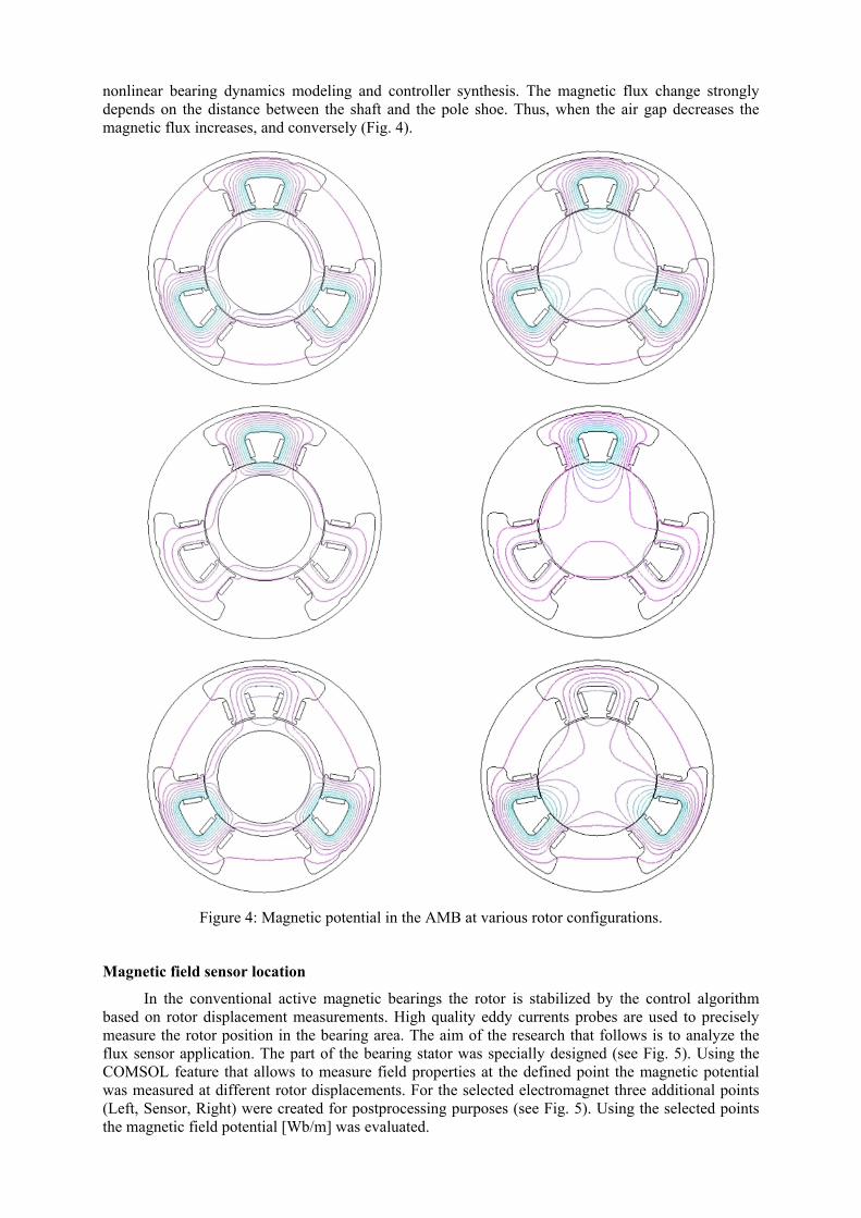
nonlinear bearing dynamics modeling and controller synthesis. The magnetic flux change strongly depends on the distance between the shaft and the pole shoe. Thus, when the air gap decreases the magnetic flux increases, and conversely (Fig. 4).
Figure 4: Magnetic potential in the AMB at various rotor configurations.
Magnetic field sensor location
In the conventional active magnetic bearings the rotor is stabilized by the control algorithm based on rotor displacement measurements. High quality eddy currents probes are used to precisely measure the rotor position in the bearing area. The aim of the research that follows is to analyze the flux sensor application. The part of the bearing stator was specially designed (see Fig. 5). Using the COMSOL feature that allows to measure field properties at the defined point the magnetic potential was measured at different rotor displacements. For the selected electromagnet three additional points (Left, Sensor, Right) were created for postprocessing purposes (see Fig. 5). Using the selected points the magnetic field potential [Wb/m] was evaluated.
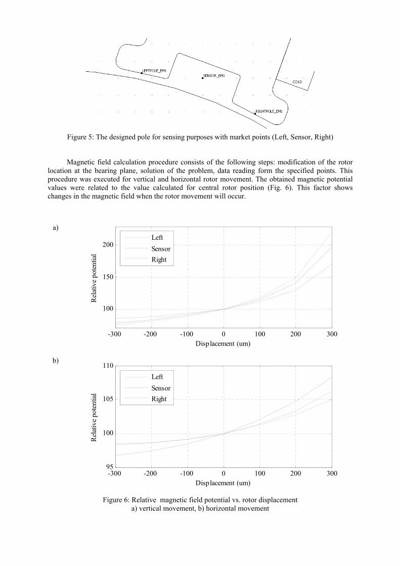
Figure 5: The designed pole for sensing purposes with market points (Left, Sensor, Right)
Magnetic field calculation procedure consists of the following steps: modification of the rotor location at the bearing plane, solution of the problem, data reading form the specified points. This procedure was executed for vertical and horizontal rotor movement. The obtained magnetic potential values were related to the value calculated for central rotor position (Fig. 6). This factor shows changes in the magnetic field when the rotor movement will occur.
a)
-300 -200 -100 0 100 200 300
100
150
200
Displacement (um)
Rel
ativ
e po
tent
ial
LeftSensorRight
b)
-300 -200 -100 0 100 200 30095
100
105
110
Displacement (um)
Rel
ativ
e po
tent
ial
LeftSensorRight
Figure 6: Relative magnetic field potential vs. rotor displacement
a) vertical movement, b) horizontal movement

The vertical movement represents the axial movement regarding to the upper stator axis. Positive values corresponds to the rotor movement in the upright directions. The horizontal rotor movement is realized in the perpendicular axis and positive values indicates the right side location. This analysis shows that the sensor can be located in the stator pole. Its displacement characteristics is nonlinear and depends on the rotor movement. For the rotor variations up to 10% of the nominal radial air gap the sensor characteristics can be successfully linearized which is favorite for the controller design and operation.
4 Conclusions Calculations based on the finite element method give a deeper insight into the phenomena in Active Magnetic Bearings. The performed analysis plays an important role in the design procedures of AMB and helps in the verification of the construction assumptions. It is essential to use appropriate materials for the shaft and stator. The pole shoes arrangement, their sizes and coil parameters strongly influence the electromagnetic force value produced by the electromagnet.
The design procedure of AMB is a complex task consisting of a few elements: analysis of the AMB operating mode parameters, calculation of electromagnetic force, selection of materials and calculation of magnetic field properties to obtain the desired force value, and the choice of controller architecture. Thus the magnetic field analysis plays an important role in the AMB development process.
Current research is focused on 2D and 3D modeling and analysis using the electromagnetic module with Simulink interactions to examine the static and dynamic AMB behavior in the real operation environment.
The application of the COMSOL package gives a possibility to establish a connection with Simulink, with data exchange. This is very useful when the pole analysis is connected with the control algorithm design. The computational effort strongly depends on the mesh density. The possibility to import DXF files allows the user to import shapes designed in another CAD application. The user must check the mesh quality and size after the import procedure from the file to COMSOL environment because of the defined accuracy and different DXF formats. Sometimes it is necessary to modify the shape manually to eliminate superfluous mesh densities.
References
[1] Piłat A., FEMLab software applied to active magnetic bearing analysis, International Journal of Applied Mathematics and Computer Science. — 2004 vol. 14 no. 4 spec. iss.: Issues in modelling, optimization and control s. 497–501
[2] Gosiewski Z., Falkowski K., Multifunction magnetic bearings, Biblioteka Naukowa Instytutu Lotnictwa. Warszawa 2003 (in Polish)
[3] Kanebako H., Okada Y., New Design of Hybrid type Self-Bearing Motor for High-Speed Miniature spindle. Proceedings of The Eighth International Symposium on Magnetic Bearings, Japan 2002, August 26-28.
[4] Ohmori K., Kim S., Masuzawa T., Okada Y., Design of an Axial-type Self Bearing Motor for Small Axial Pump. Proceedings of The Eighth International Symposium on Magnetic Bearings, Japan 2002, August 26-28.
[5] Comsol 3.3 User’s Guide and Introduction, Comsol AB, Sweden 2006. [6] Rothwell E.J., Cloud M.J., Electromagnetics, CRC Press 2001 [7] Hammond P., Sykulski J.K., Engineering Electromagnetism – Physical Processes and
Computation, Oxford University Press, New York 1994.
Acknowledgement. The author thanks the company Technika Obliczeniowa (www.tobl.com.pl) for the test version of the COMSOL 3.3 software and conference sponsorship.