selecte dti - defense technical information center monterey, california selectedti nov0 5 1993uc s a...
TRANSCRIPT

I lI I I I III-i
0• NAVAL POSTGRADUATE SCHOOLMI Monterey, California
DTISELECTENOV0 5 1993Uc
S A 33 GR AD'a P:
THESISCONTROL VANE GUIDANCE FOR
A DUCTED-FAN UNMANNED AIR VEHICLE
by
Patrick J. Moran
June, 1993
Thesis Advisor: Richard M. HowardCo-Advisor: Michael K. Shields
Approved for public release; distribution is unlimited.
93-27039

BestAvai~lable
Copy

UnclassifiedSecurity Classification of this page
REPORT DOCUMENTATION PAGEia Report Security Classification: Unclassified lb Restrictive Markings
2a Security Classification Authority 3 Distribution/Availability of Report
2b Declassification/Downgrading Schedule Approved for public release; distribution is unlimited.
4 Performing Organization Report Number(s) 5 Monitoring Organization Report Number(s)
6a Name of Performing Organization 6b Office Symbol 7a Name of Monitoring Organization
Naval Postgraduate School (if applicable) 31 Naval Postgraduate School
6c Address (city, state, and ZIP code) 7b Address (city. state, and ZIP code)
Monterey CA 93943-5000 Monterey CA 93943-5000
Ss Name of Funding/Sponsoring Organization t6b Office Symbol 9 Procurement Instrument Identification NumberI (if applicable)
Address (city, state, and ZIP code) 10 Source of Funding Numbers
Program Element No IProject No ITsk No IWork Unit Accession No
I I Title (include security classification) Control Vane Guidance for a Ducted-fan Unmanned Air Vehicle
12 Personal Author(s) Patrick J. Moran
13a Type of Report l3b Time Covered j14 Date of Report (Year, mnonth, day) 1i5 Page Count
Master's Thesis ]From To June 1993 1 112
16 Supplementary Notation The views expressed in this thesis are those of the author and do not reflect the official policy or positionof the Department of Defense or the U.S. Government.
17 Cosati Codes 18 Subject Terms (continue on reverse if necessarv and identify by block number)
Field Group [Subgroup AROD, Aquila, UAV, control, Pulse-width Modulation, Archytas, Humphrey Sensors,SFutaba Servo Control, SISO control
19 Abstract (continue on reverse if necessary and identify by block number)
Control of airborne vehicles was originally conceived to be done entirely by human pilots. Improvements in electronics in thelast 50 years have allowed many flight control functions to become automated, with the pilot continuously monitoring flightparameters from within the vehicle cockpit. With the advent of small unmanned air vehicles (UAV's), which are limited in sizeand weight-carrying capacity, a pilot is now able to fly an airborne vehicle from a distant ground-fixed position. Miniatureelectronic instruments control or direct vehicle movements either through pilot commands or autonomously. In order toaccomplish reliable, continuous control of a UAV, many sensors are necessary aboard the vehicle. This thesis designed andinstalled necessary hardware and developed software to guide a UAV's aerodynamic control vanes, with feedback from sensorsaboard the vehicle, in order to facilitate ground-based pilot control. Previous thesis work accomr.,shed on this project achievedcontrol of a UAV, named Archytas, in one degree-of-freedom, roll, while mounted on a test stand. Umbilical-controlled guidanceof Archytas' control vanes from a forward-mounted sensor pod was set as the goal for this phase of the Archytas project. Thiswork focused on modification of hardware to generate and access required signals, programming of analog-to-digital (A/D) andcounter/timer peripheral boards mounted in a personal computer to control electrical and signal flow, and implementation of single-input-single-output (SISO) control equations developed concurrently in another thesis.
20 Distribution/Availability of Abstract 21 Abstract Security Classification_unclassified/unlimited _ same as report _ DTIC users Unclassified
22a Name of Responsible Individual 22b Telephone (include Area Code) 22c Office Symbol
Richard M. Howard and Michael K. Shields (408) 656-2870, 656-2979 AAIHo, EC/Sh
DD FORM 1473,84 MAR 83 APR edition may be used until exhausted security classification of this page
All other editions are obsolete Unclassified
l I . .

Approved for public release; distribution is unlimited.
CONTROL VANE GUIDANCE FOR
A DUCTED-FAN UNMANNED AIR VEHICLE
by
Patrick J. Moran
Lieutenant Commander, United States Coast Guard
B.S., United States Coast Guard Academy, 1981
Submitted in partial fulfillment
of the requirements for the degree of
MASTER OF SCIENCE IN AERONAUTICAL ENGINEERING
from the
NAVAL POSTGRADUATE SCHOOL
June 1993
Author: _ _ _"_ t __.
Sick J. Moran
Approved by: 1?k"4 4IRichard M. Howard, Thesis Co-Advisor
Michael K. Shields, Thesis Co-Advisor
Daniel . Collins, Chairman
Department of Aeronautics and Astronautics
ii

ABSTRACT
Control of airborne vehicles was originally conceived to be done entirely by human
pilots. Improvements in electronics in the last 50 years have allowed many flight control
functions to become automated, with the pilot continuously monitoring flight parameters
from within the vehicle cockpit. With the advent of small unmanned air vehicles
(UAV's), which are limited in size and weight-carrying capacity, a pilot is now able to
fly an airbornt- vehicle from a distant ground-fixed position. Miniature electronic
instruments control or direct vehicle movements either through pilot commands or
autonomously. In order to accomplish reliable, continuous control of a UAV, many
sensors are necessary aboard the vehicle. This thesis designed and installed necessary
hardware and developed software to guide a UAV's aerodynamic control vanes, with
feedback from sensors aboard the vehicle, in order to facilitate ground-based pilot
control. Previous thesis work accomplished on this project achieved control of a UAV,
named Archytas, in one degree-of-freedom, roll, while mounted on a test stand.
Umbilical-controlled guidance of Archytas' control vanes from a forward-mounted sensor
pod was set as the goal for this phase of the project. This work focused on modification
of hardware to generate and access required signals, programming of analog-to-digital
(A/D) and counter/timer peripheral boards mounted in a personal computer to control
electrical and signal flow, and implementation of single-input-single-output (SISO){ Accesion For --4
control equations developed concurrently in another thesis, NTIS CRA&M 1
DTIC TAB -
dJo,.ihfcation
By .By...................
AvailaL,,:-v I ,j~ •A vw !I _1 [: ,':,,'
*;7t -''St.-,-.

TABLE OF CONTENTS
I. INTRODUCTION .................................... 1
1I. BACKGROUND ..................................... 4
A. GENERAL INFORMATION ON UAV'S ................. 4
B. ARCHYTAS CONCEPT EVOLUTION .................. 6
1. A RO D .................... .......... ..... . 7
2. A quila . . . . . . . . . . . .. .. . . .. . . . . . . .. . . .. . . . . . 9
3. The Archytas UAV ............................ 11
m. GROUND CONTROL EQUIPMENT ........................ 15
A. COM PUTERS .................................. 17
B. PC PERIPHERAL BOARDS ......................... 17
1. Counter/timers: 'Quartz' and 'CIO-CTR' .................. 17
2. A/D Boards: 'CIO-ADI6jr' and 'DAS-16' ................. 19
C. CONTROL JUNCTION BOARD AND UMBILICAL CORD ...... 20
IV. ON-BOARD VEHICLE EQUIPMENT ...................... 25
A. FOREBODY ................................... 25
iv

1. SAS Sensors ................................ 28
a. Angular Rate Sensors ........................ 30
b. Vertical Gyroscope ......................... 30
2. SAS Sensor Mod ling.g ........................... 32
a. Angular Rate Sensors ........................ 32
b. Vertical Gyroscope ......................... 33
3. Forebody Interconnections ........................ 34
B. CHASSIS ..................................... 34
1. Diode Rectifier Board ........................... 35
2. Signal Distribution Buses ........................... 35
3. Engine .......... ................ .. ........ 38
C. REARBODY ................................... 38
1. Control Vane and Throttle Servos . ................... 40
a. Futaba Servos ............................ 40
b. Condor Servos ........................... 42
c. Servo M odeling ........................... 42
d. PWM Servo Control ........................ 43
2. Ignition and Tachometer ......................... 45
3. Alternator .................................. 45
D. VEHICLE INTERCONNECTIONS ....................... 46
V
V. CONTROL VANE GUIDANCE 'C' ROUTINES ................... 50
A. PWM VANE CONTROL ROUTINES....................... 51
1. Basic PWM Control Using Counter/timer Board ............ 51
2. PWM Signal Control Via A/D Board ................. 54
B. SISO ROLL CONTROLLER ROUTINE .................. 55
C MIXED CONTROL SURFACE GUIDANCE ROUTINE ........ 55
VI. SYSTEM EVALUATION AND RESULTS ................... 60
A. VEHICLE AND GROUND CONTROL EQUIPMENT
EVALUATION ................................. 60
1. Ground Control Equipment ....................... 60
2. On-board Vehicle Equipment ...................... 61
B. CONTROL ROUTINE EVALUATION .................. 64
1. Implementation of SISO Controller ................... 65
2. Dual Joystick Control Vane Guidance ................... 66
C. SUMMARY OF RESULTS .......................... 66
VII. CONCLUSIONS AND RECOMMENDATIONS .................. 68
APPENDIX A: 'C' PROGRAMS DEVELOPED FOR THE ARCHYTAS UAV 70
APPENDIX B: HARDWARE SPECIFICATIONS .................. 80
vi

APPENDIX C: SCHEMATICS- AROD-3 AND ARCHYTAS ............ 95
APPENDIX D: ARCHYTAS UAV ENGINE RUN CHECKLIST ........... 99
LIST OF REFERENCES .................................. 100
INITIAL DISTRIBUTION LIST .............................. 102
vii

LIST OF FIGURES
Figure 1 Three-view Sketch of Archytas UAV General Configuration ........ 8
Figure 2 AROD UAV Two-view Sketch and Aquila RPV Three-view Sketch 10
Figure 3 General Block Diagram of the Archytas UAV Control System ...... 13
Figure 4 Archytas UAV Ground Equipment Block Diagram .............. 16
Figure 5 Control Junction Board Photograph ..................... 21
Figure 6 Archytas UAV On-Board Equipment Block Diagram ........... 26
Figure 7 Photograph showing Archytas Forebody/Chassis/Rearbody Assembly 27
Figure 8 Photograph of SAS Sensors mounted in Forebody ............. 29
Figure 9 Axis and Vane Numbering Conventions for the Archytas UAV . . .. 31
Figure 10 Phot, of Chassis-mounted Diode Rectifier Board (TSB5) ........ 36
Figure I 1 Schematic of Diode Rectifier Board (TSB5) with 3-Phase AC Input 37
Figure 12 Photograph of Chassis Bus Board ...................... 39
Figure 13 Photograph of Rearbody/Chassis Assembly .................. 41
Figure 14 Typical PWM Waveform ........................... 44
Figure 15 Flow Chart for pwm.c Routine ........................ 52
Figure 16 Flow Chart for atod.c Routine ....................... 53
Figure 17 Flow Chart for roll.c Routine ........................ 56
Figure 18 Flow Chart for ai el ru.c Routine ..................... 59
viii

I. INTRODUCTION
Unmanned air vehicles (UAV's) can offer many benefits to potential users, such
as relatively low procurement cost, low cost per flight hour, portability, and simplicity
of operation. UAV's are also known as remotely piloted vehicles or RPV's. The term
'UAV' is preferred, denoting an air vehicle often flown autonomously. When studied
in an academic environment, such as the Naval Postgraduate School's (NPS) UAV Flight
Research Laboratory, UAV's offer students and faculty the ability to safely and
inexpensively flight test different aircraft designs, configurations, or technologies.
Vehicles can be equipped with radio-frequency (RF) uplinks, allowing thorough
command of flight conditions. Additionally, UAV's can be instrumented to send data
via RF downlinks so that flight parameters can be observed real-time during flight, or
recorded for later analysis. Unique or novel designs can be developed to serve special
purposes or missions, which may not be achievable or economically feasible using full-
scale piloted aircraft. Safety is another benefit of UAV flight research, as personnel are
at minimal risk while a vehicle is airborne during flight testing.
In order to accomplish safe, reliable, and continuous control of UAV platforms,
a stability augmentation system (SAS) is often required. A SAS coprsists of motion
sensors, an inertial measurement unit (IMU), a filtering scheme such as Kalman filtering,
a navigation system such as GPS (global positioning system), and a microprocessor to
perform calculations, all mounted aboard the UAV. The SAS sends command outputs
" " • .., Ii if if i Ie Ii i

to the vehicle's aerodynamic control surfaces, which then guide the vehicle's trajectory,
either through pilot inputs or -,*.onomously. [Ref. I]
This thesis detail, .e design and installation of a suite of sensors which provide
necessary feedback signals to support the SAS of the prototype Archytas UAV in a
hovef'.1., flight mode. Later phases of the Archytas project will add additional SAS
elements to achieve more complicated flight conditions. Software algorithms which
implement the control laws to guide the vehicle's aerodynamic control vanes were
developed. Algorithms were encoded using the 'C' programming language. An external
personal computer (PC), connected to Archytas through an umbilical cord, served as the
onboard microprocessor to test the algorithms. Commands were sent to the control vanes
either from two joysticks on a control station via umbilical, which represented the RF
transmitter, or as a result of control algorithm feedback from the SAS. The algorithms
and control system were tested by simulating various inputs, either joystick or sensor
generated, and observing appropriate vane responses.
This project continued work begun by Merz [Ref. 2] and Davis [Ref. 3], which
implemented a one degree-of-freedom SAS and core control system for the aerodynamic
control vanes. Several concurrent student theses in progress will continue to develop
other aspects of the SAS, including the IMU, GPS, MIMO controller and Kalman filters,
so that the combined theses will contribute to the final design of the Archytas SAS.
This investigation examined:
0 The ground control equipment necessary for umbilical-controlled flight of theArchytas UAV including the PC's required for generation of control signals, the
2

control junction board on which two joysticks and associated control switches weremounted, and the umbilical cord.
"* The redesign of on-board vehicle hardware, including reconfiguration of thepreviously-designed sensor pod from the vehicle's rearbody to a forebody mountedon struts above the vehicle intake. All wiring harnesses and associated bus boardswere connected to accommodate the redesign.
"* The modification of 'C'-coded software to generate pulse-width modulated (PWM)signals through programming of counter/timer and analog-to-digital (A/D) boardsmounted within the PC's. The PWM signals were used to drive servos which inturn positioned the UAV's four control vanes and throttle.
"* The implementation of a single-input-single-output (SISO) and multiple-input-multiple-output (MIIMO) controllers as progressive steps toward achieving hoveringflight of the Archytas UAV.
This thesis consists of six chapters, including this introduction. Chapter HI
summarizes evolution of the Archytas project. Chapter III details the ground equipment
required for this phase of the project. Chapter IV describes the vehicle's on-board
equipment and systems, such as sensors, servos, and signal distribution. Chapter V
concerns implementation of control algorithms which develop pulse-width modulated
signals to drive the vehicle's control vanes. Finally, Chapter VI deals with system
evaluation, results achieved, conclusions derived, and recommendations for future
improvements to the system. Appendix A contains 'C' routine listings developed for the
project. Appendix B includes plug diagrams, and sensor and peripheral hardware
specifications. Appendix C contains schematic diagrams used extensively in the vehicle's
signal and electrical connections. Finally, Appendix D is an engine-run safety checklist
developed to ensure that proper safety precautions were adhered to during engine runs.
3

I. BACKGROUND
This chapter begins with a summary of Close-range UAV requirements, and
follows with a development of the history of the Archytas project to date. Archytas
UAV project mission and goals are also described.
A. GENERAL INFORMATION ON UAV'S
The DoD Unmanned Aerial Vehicles Joint Project Office (UAV JP), which
oversees military unmanned air vehicle programs, classifies UAV's into four categories
based on a vehicle's intended operating range or endurance:
"* Close-range: 30-50 km range,
"* Short-range: 150 km range,
"* Medium-range: 650 km range,
"* Endurance: up to 24 hour flight time.
Close-range UAV's tend to be small, portable vehicles with minimal support equipment.
Short-range UAV's are generally larger, requiring incrementally more support equipment
and personnel for operation. Medium-range UAV's rival manned aircraft in size, speed,
and endurance, and are similar to non-lethal cruise missiles. Endurance UAV's tend to
be large in size with glider-like wingspans, and have a desired endurance on the order
of days. [Ref. 4]
4

The Archytas project is directed toward the Close-range UAV category. A Close-
range UAV would ideally be employed at Marine Corps expeditionary unit (MEU) or
Army battalion level for battlefield intelligence surveillance. Historically, UAV designs
require prepared runway surfaces on which to conduct flight operations. This
requirement has tended to limit UAV usefulness in battlefield scenarios, which often do
not allow the luxury of a dedicated, prepared runway. Previous designers have overcome
this shortcoming by using pneumatic launchers or rocket-assisted takeoffs (RATO), but
such methods require numerous personnel and bulky support equipment, severely
restricting overall UAV system portability. To that end, the UAV JP Master Plan for
1992 included a requirement for a VTOL (Vertical Take-off and Landing) UAV system,
which must be able to operate from U.S. Navy surface combatants. VTOL UAV
specifications call for a 135 kt cruise speed, 110 run radius of action, 3 hour loiter time
at 110 rim, and 12,000 ft operating altitude. [Ref. 5, pp. 34-6]
A configuration which could meet UAV JP requirements is a hybrid VTOL, which
would take-off vertically, using very little ground/deck space. Once airborne the vehicle
would transition to horizontal flight to take advantage of the improvements in speed,
range, and loiter time which horizontal fixed-wing flight provide. [Ref. 6]
The Archytas UAV is an NPS UAV Flight Research Laboratory project currently
under development. The ducted-fan, tail-sitter configuration of Archytas is a VTOL
platform being investigated to explore technologies related to the VTOL UAV mission.
Archytas' namesake was a citizen of ancient Greece and colleague of Plato credited with
having designed, constructed, ana flown the first mechanical bird. [Ref. 6]
5
The U.S. Coast Guard is closely following the development of prototype vehicles
which are designed to meet the VTOL UAV specifications. The potential benefits from
UAV technology for the Coast Guard's law enforcement efforts are numerous. UAV's
could be operated from strategic island locations throughout the Caribbean much more
efficiently than costly manned aircraft. Also, Coast Guard ships are similar in size to
the small surface combatants specified in the VTOL UAV specifications. As the Coast
Guard's research and development budget is far less than DoD's, any technologies
advanced by DoD research facilities, such as the Naval Postgraduate School, are
frequently later employed by the Coast Guard.
B. ARCHYTAS CONCEPT EVOLUTION
The Archytas UAV is mainly built from the assets of two previously cancelled DoD
developmental UAV programs, the U.S. Marine Corps' AROD program and the U.S.
Army's Aquila program, both of which are described below. The Archytas mission
requires a lightweight, inexpensive UAV which, due to its VTOL capability, can be
operated from very confined locations, including flight decks of ships at sea. In its
current configuration, Archytas is not specifically designed to meet VTOL UAV
requirements. But as a VTOL technology demonstrator, it has the potential to validate
the concept of a ducted-fan, tail-sitter-configured UAV, and to design, test, and validate
sensor and software requirements for guidance, navigation, and control of such a
platform.
6

Previous work in the NPS UAV Flight Research Lab achieved design and initial
testing of a preliminary half-scale version of the Archytas concept. This work introduced
the ducted-fan-in-fuselage configuration, although the original concept had been to keep
the wings horizontal during hover, rotating only the duct and engine to transition from
hover to forward flight [Ref. 7]. The new Archytas configuration, a tail-sitter design
with a rigidly-mounted duct, was chosen due to the availability of useful assets and its
design simplicity. The Archytas UAV's current configuration is shown in a three-view
sketch with approximate dimensioaý, in Figure 1.
Assets remaining from the cancelled AROD and Aquila programs have been
acquired by NPS. Elements of each design are being used to further explore the ducted-
fan-in-fuselage, tail-sitter UAV configuration. Positive aspects of each design are
combined in the Archytas design to form a more efficient, more capable platform than
either AROD or Aquila. The following sections describe each vehicle, then how they
are combined to form the Archytas UAV.
1. AROD
The U.S. Marine Corps identified a requirement in the late-1970's for an
MEU-level intelligence gathering tool, and so commissioned the development of a Close-
range UAV to fill that need. Program development was engineered by Sandia National
Laboratory at Albuquerque, New Mexico, in conjunction with the Naval Ocean System
Command, in the mid-1980's. The result of their design efforts was the Airborne
Remotely Operated Device, or AROD. AROD was built to fly strictly in a hover or
vertical flight mode. While filling the requirement for operation from unprepared areas,
7

Dimensions Approximate
176" -- --
LK 30" -~
Chassis i
Figutre I ThIiee-view Sketc (i f Archyyts IJAV Gei'iicrl Coiifigut;tli4)n
8

the configuration was lacking in that its vertical flight mode was inherently inefficient for
transitional flight. Its ducted-propeller design did offer the advantage of safety when
operated in close proximity to ground personnel, as well as high thrust efficiency.
AROD was intended to be controlled primarily through a fiber-optic (FO) link, with RF
control available for backup and as a training aide [Ref. 8]. It first flew successfully in
1986, but never went into production. One problem the AROD design suffered from
severe vibration. Also, an updated requirement by the newly-formed UAV JP called for
the UAV to be able to achieve translational flight, rather than simply hovering flight,
which AROD was not designed to do. The AROD project was cancelled in 1987 due to
budget cutbacks [Ref. 6]. Equipment assets remaining from the AROD program were
acquired by NPS in 1992. Those assets provide much of the hardware which now makes
up Archytas' fuselage and electronics. A two-view sketch of AROD is shown in
Figure 2.
2. Aquila
Prior to the AROD program, the U.S. Army developed a short-range UAV,
named Aquila, which also never saw operational employment. A pure fixed-wing design
engineered by the Lockheed Corporation, Aquila was launched from a pneumatic launch
device mounted on a large truck. Aquila was a delta-wing configured RPV, with a
wingspan of 12 feet 9 inches. It was powered by a 2-stroke, 2-cylinder gasoline engine,
which drove a pusher propeller. Figure 2 shows the general Aquila configuraticn in a
three-view sketch. The Aquila engine, a Dyae 'K) r ,-de by Herbrandson Engines, Inc.,
was derived from a commercial chainsaw engine. Coincidentally, the same engine was
9

AROD UAVElectronics
SForebody
Top View
Profile View, Symmetrical
Aquila RPY-
Front View
Enin~~SSiderView
Figure~~~~.... 2....w.etho RDUA n he-ve ktlofAul P
........

later chosen by Sandia Laboratory for AROD [Ref. 4]. Like the AROD project, the
Aquila project was cancelled due to budget cutbacks. The wings from Aquila, which
were reflexed to provide longitudinal stability for Aquila's delta-wing shape, are used in
the Archytas design by adapting them to mount on an AROD fuselage [Ref. 6]. Figure 2
also shows a three-view sketch of the Aquila RPV.
3. The Archytas UAV
Archytas project goal is to couple the hovering takeoff and landing benefits
of AROD with the inherently more efficient and faster horizontal flight characteristics
of Aquila. Archytas was designed in a tail-sitter configuration with the AROD body
forming the Archytas fuselage and Aquila's wings providing horizontal flight lift. A
forward canard was added to provide longitudinal stability in horizontal flight.
AROD's electronics were originally mounted around the exterior shell of its
chassis. They were relocated to a pod mounted above its intake duct for center-of-
gravity (CG) and vibration considerations. In the initial stages of the Archytas design,
the pod was moved aft of the engine and control vanes so as not to impede intake airflow
and to ease implementation of the electronics suite [Ref. 2]. Later, longitudinal stability
calculations determined that Archytas, like AROD, needed to have the pod forward for
CG considerations, despite the potential airflow hinderance [Ref. 9]. Also, experience
with the rearbody-mounted electronics pod during engine runs revealed that severe
vibration generated by the vehicle's 2-cycle engine was being transferred to the pod. The
vibration led to numerous component failures, which served to reinforce the decision to
move the electronics pod to the forebody location.
11

Archytas uses the Aquila and AROD 26-horsepower engine for propulsion.
The engine, coupled with a three-bladed ducted propeller, provides approximately 120
lbs of thrust to propel Archytas. To accomplish vertical take-off and landing, only 25
lbs of excess thrust are available. This limits the amount of equipment and payload the
vehicle can carry. All of AROD's original fiber optic control equipment and
surveillance systems were stripped from its fuselage, which then became the Archytas
fuselage. Only the minimum equipment necessary for prototyping the concept was
retained. A minimal fuel system is employed, again only for validation of the concept.
Future goals of the Archytas project are to optimize the tail-sitter VTOL
configuration by adding state-of-the-art sensors, GPS receivers, and on-board
microprocessors, allowing for fully autonomous flight guided through a MIMO
controller. Uplinks and downlinks will provide continuous vehicle command and
monitoring of flight parameters.
A general block diagram of the Archytas UAV control system developed in
this thesis is shown in Figure 3. The following two chapters will detail the ground
control equipment and on-board vehicle equipment shown in the diagram.
Chapter V then discusses the control vane guidance algorithms written to
control the system. In general, the system works through sensors aboard the Archytas
which sense vehicle motions and output analog signals. The sensor signals are
conditioned aboard the vehicle to the proper voltage ranges, then are sent to the PC via
the umbilical cord and control junction board. This information is used by a pilot, or
a control algorithm, to guide the vehicle. Pilot inputs from two joysticks mounted on the
12

................. . .....
----------.. .. .. .. ...-Vertical Gyro
IVane3Archytas Sensor! -- ------Vehcl c ~Oupus Pitch&Yaw':
c k .. . . . ..- -4 ...... I ........ ............ .. ..
Vehicle ........... Rate SensorPw M I----.........-
Signals I Servo i Roll Rate.------t- .Positions I Sensor
Umbilical orK lL, .
SSwitch "Joystick .7l Control"a's'n"00 .......... I Jnto28V External "'Jo'--h,°b
2Vower Sappl -- *Ext Powei# "Joystick) BoardPower Supply --------*
ll "Patch CablesTo/From PC
--------. ...-- / " .. . .........
Counter/Timer ! o IBor AM N Board
Value ScuPC PwM I IDiital
Values I-------------Sensor"C Routine: '. Info
. SISOorMIMO ,
\ Controller .:
Figure 3 General Block Diagram of the Archytas UAV Control Sysleni
13

control junction board are converted from analog signals to digital numbers and are sent
to the counter/timer boards in the PC, possibly via a control algorithm, to generate
pulses. The pulses vary in width proportionally to the desired position of the servos.
These pulses are then sent back to the vehicle via the umbilical cord to guide servos
attached to the vehicle's control surfaces and throttle.
14

M. GROUND CONTROL EQUIMENT
The ground equipment necessary to control Archytas in this phase of development
is described in this chapter, as depicted in Figure 4. Much of the equipment was unique
to this phase of the project, and will either be removed or relocated as the Archytas
project progresses. For instance, the external PC which controls generation of pulse-
width modulated (PWM) signals will be replaced in a future developmental phase by a
486 CPU aboard the vehicle to perform the same function. When this occurs, many
umbilical cord functions will no longer be necessary. Commands will be passed between
the pilot and vehicle by data link. It should be evident that many other changes in
configuration will occur as the project progresses.
As described in Chapter I, the Archytas UAV will eventually have a self-contained
stability augmentation system (SAS) aboard the vehicle centered around a micro-
processor. To ease implementation and design of the SAS, it was felt that development
should begin with an umbilical cord control system, with the micro-processor role being
accomplished by an external PC. This would allow for developing the RF data link at
the same time that the control system was being developed. A method of passing
information to the PC via the umbilical cord, then transmitting commands back to the
vehicle, was developed independently at this stage of design. Equipment necessary to
accomplish this process included the PC's, the associated counter/timer and analog-to-
digital boards, the control junction board which is the mounting location for two joysticks
15

ArchytasVehicle
Umbilical JlCord
..... ..... , ".. . .,iSwitch , i"oystick 2¶ Control/~ Junction
28V External - - DC . . . : .. g. t B oPower Supply "Ext Powef kioyik.. Ba
JTPitch CablesTo/From PC
SCountepJ[rime !r: Bonrd . AMD Board
D O S...)-- ...................
PC PWM IDigitalValues --------------- Sensor
I°"'C' Routine: Info
p _
\ControllerValues-------------------Sno
Figure 4 Archylas UAV Ground Equipment Block Diagram
16

and associated switches, and the umbilical itself. This equipment is described in this
chapter.
A. COMPUTERS
The NPS UAV Lab operates two IBM-compatible PC's, a RAMPCOM 486DX 50
MH1z and an IBM AT retrofitted with an OPTi 386DX 25 MHz motherboard. Both were
used in development of 'C' routines written for Archytas using a Borland 'C' compiler.
The 'C' programming language was used by Merz [Ref. 2] to develop initial PWM and
A/D routines because it is relatively user-friendly and is widely used in engineering
applications. Later phases of development necessarily follow the same 'C' conventions.
Two peripheral boards, described in the next section, were used in each computer to
control signals coming to and from the PC's through 'C' routines.
B. PC PERIPHERAL BOARDS
1. Counter/timers: 'Quartz' and 'CIO-CTR'
In order to develop PWM signals, a method of regulating the duration of each
pulse was required. Two counter/timer boards, 'Quartz' made by Diamond Systems
Corporation and 'CIO-CTR' made by Computerboards Inc., were used to generate PWM
signals to control the aerodynamic control vane servos and the throttle servo. These
boards were programmed to regulate pulses to a desired width and repetition rate.
Specific register-level programming instructions for each board, as well as the A/D
boards described in the following section, were well-documented by Merz [Ref. 2,
17

Chapters IV and V]. Both boards employ an Am 9513A counter/timer microchip as the
heart of their circuitry. This compatibility allowed 'C' routines to be run interchangeably
through either board in either computer. The Am 9513A chip has five individual
counters, as well as a user-selectable frequency oscillator. The CIO-CTR board was
configured with two Am 9513A chips, allowing the use of 10 counters, although this
feature was not used since only five counters were necessary. The only difference
operationally between the boards was their different connector plugs: Quartz used a 50-
pin plug, while CIO-CTR used a 37-pin connector. This required the control junction
board, which connected PC cables to the umbilical, to have adapters for both plug
arrangements. The pin-out diagrams and necessary connections for each counter/timer
are shown in Appendix B. Initial DIP switch settings for each board, which define the
board's operating modes, are defined in Table 1.
TABLE 1: COUNTER/TIMER BOARD DIP SWITCH SETTINGS
Board Base Address Interrupt Wait State
Quartz 220 Hex 5 N/A
CIO-CTR 220 Hex X (No IRQ) On
18

2. A/D Boards: 'CIO-ADI6jr' and 'DAS-16'
An A/D board converts analog voltage signals to digital numbers, which can
then be manipulated by software and the counter/timer boards to produce PWM signals.
The A/D boards used were the 'CIO-ADl6jr' made by Computerboards Inc., and 'DAS-
16' made by the Metrabyte Corporation. Like the counter/timer boards, both A/D
boards employed compatible microprocessors and timers, the Intel 8254 programmable
interval timer, to complete the A/D conversion process. Again, the boards'
compatibility allowed for 'C' routines to be run interchangeably on either computer.
Both A/D boards used similar 37 pin plugs, but different pin arrangements. Fortunately,
the pins used for Archytas were the same on both plug arrangements, easing
interoperability. The pin-out diagrams for each A/D board and the necessary
connections are shown in Appendix B. The initial DIP switch settings for each AID
board are shown in Table 2.
TABLE 2: A/D BOARD DIP SWITCH SETTINGS
Board Base Address Channel Clock DMA Input Range
CIO-AD16jr 300 Hex 16 1 1 Software-Driven
DAS-16 300 Hex 16 N/A I 1 1000
19

C. CONTROL JUNCTION BOARD AND UMBILICAL CORD
Commands which guide Archytas' control vanes and throttle were made using two
joysticks mounted on a control junction board. Earlier generation routines by Merz
[Ref. 2] used input from only one joystick. The joysticks were arranged in a layout
similar to that of a standard radio-control (RC) transmitter. The left joystick, taken from
a surplus Futaba transmitter, controlled inputs to the rudder (left/right, spring-centered)
and throttle (up/down, not spring-centered). The right joystick, taken from a surplus
AROD ground control station, commanded ailerons (left/right, spring-centered) and
elevator (up/down, spring-centered).
A photograph of the control junction board in its current configuration is shown in
Figure 5. It shows the dual joysticks, umbilical cord connections, PC patch cables, kill
switch, and DC external power connections.
A remote kill switch, which was a direct tap into the engine's ignition wire through
the umbilical cord, was also mounted on the control junction board. The entire control
junction board will eventually be replaced by an actual RC transmitter in a later project
phase when the umbilical is no longer required.
Each joystick single degree-of-freedom had a different voltage range from its lower
limit to upper limit. The left stick also was equipped with trim knobs for each degree-of-
freedom. To prevent inadvertent movement of the trim knobs, the knobs were taped in
the full down position for throttle, and centered position for rudder to ensure consistent
voltage outputs. The analog voltage difference from each joystick output, when passed
through the A/D board, translated to a range of digital values. The A/D board used a
20

Figwure 5 Control Junction Board Photograph
21

12-bit conversion, so that a 0 to 5 volt analog range translated to a 0 to 4096 digital
range. Table 3 lists the minimum, center, and maximum digital units for each stick's
two degrees-of-freedom. These values were recorded empirically.
TABLE 3: JOYSTICK DIGITAL UNIT RANGES
(AFTER A/D CONVERSION)
Joystick Minimum Center Maximum Minimum Center Maximum
(Down) (Up) (Left) (Right)
Left 2490 N/A 3140 1600 1150 720
Right 1850 2260 2650 2470 2090 1680
The umbilical cord used consisted of shielded six-twisted-pair cable, obtained from
surplus telephone cable. Since 21 signals needed to be transferred from the ground
station to/from the vehicle, two cables were used side-by-side. The two cables were
labelled '1' and '2' and tie-wrapped together for security. Signal flow through the
umbilical is charted in Table 4 The vehicle's umbilical connection was at the lowest
point of the rearbody. The ez-1cap which would have normally been located at the
bottom of the rearbody was replaced by a surplus forebody topcap. This arrangement
allowed an easier and more secure method of mounting the umbilical cord to the vehicle.
The Cannon plug connections at the vehicle end and wiring connections at the control
junction board end of the umbilical cord are shown in Appendix B.
22

TABLE 4. UMBILICAL CORD SIGNAL FLOW
Total Wires: 21, plus shield & chassis ground. 23 of 24 Umbilical Pins Used.
To Vehicle fm Control Junction Board Fm Vehicle to Control Junction Board
4 Vane Command Signals: 3 Rate Signals: Roll, Pitch & Yaw Rate
Vanes 1, 2, 3, & 4 3 Control Positions:
1 Throttle Command Signal Aileron, Elevator & Rudder Position
2 Kill Switch Leads to Ignition 2 Vertical Angles: Pitch & Yaw
External Power: 1 Tachometer Signal
28V DC & Reference (2 of each) I Common
The control junction board also provided a convenient mounting location for
external 28V DC power connections. External DC power was passed through the
umbilical cord for use whenever the vehicle's engine-driven alternator was not supplying
power. This also allowed operation of the vehicle engine with external electrical power
supplying the vehicle. The alternator could then be disconnected for troubleshooting
electrical system problems.
In summary, the ground control equipment described in this chapter includes:
"* PC to perform micro-processor calculations via 'C' programming;
"* Counter/timer board mounted within the PC to generate PWM signals;
"* A/D board mounted within the PC to convert analog voltage signals fromsensors and joysticks to digital values for PWM generation;
23

* Control junction board to serve as a connection point between the umbilicalcord and PC counter/timer and A/D patch cables, and as a mounting locationfor two pilot joysticks and a remote kill switch.
In a later phase of the Archytas project, the external PC will be replaced by a 486 CPU
aboard the vehicle. This will occur after all umbilical cord testing has been successfully
accomplished and an RF data link has been developed. The control junction board's
joysticks will be replaced by joysticks on an RC transmitter. The remote kill switch will
be operated through a dedicated servo on the vehicle commanded from a switch on the
RC transmitter. A receiver and antenna will be mounted on the vehicle to complete the
RF data link for control and flight parameter information transmission.
24

IV. ON-BOARD VEHICLE EQUIPMENT
The Archytas UAV fuselage, as depicted in Figure 6, can be divided into three
sections: the forebody, located on thin aluminum struts above the intake; the chassis,
which is the main Archytas body made from the AROD fuselage; and the rearbody,
which is below and inside of the chassis. Equipment related to this thesis was located
in or on all three sections. A schematic diagram drawn for the AROD project was used
extensively for forebody/chassis/rearbody wiring connections. The schematic is included
in Appendix C in two diagrams titled "AROD-3 SCHEMATIC" and "SHEET 2 OF 2."
Several full-size blueprint copies of the schematic are available in the NPS UAV Lab for
closer inspection. Schematic diagrams of the Archytas control system are also included
in Appendix C. A photograph of the Archytas forebody/chassis/rearbody assembly is
shown in Figure 7.
A. FOREBODY
The forebody is a pod mounted on tubular aluminum struts above the engine intake.
It houses the SAS sensors, signal conditioning circuit boards, and DC power distribution
boards. A 28V fan mounted in the forward end, or top, circulates air within the pod for
cooling. Electrical connections to the forebody are made through Cannon plugs located
adjacent to the four strut mounting points. Connecting wire harnesses are guided down
each strut and around the outside of the intake to the chassis. Individual components
25

(....Vane fl.... ---
%•............. .o .. . .. . .,
----------------- V e a Gyro :
VanefI 2aS ........... ":
Archytas v''------------- .......... e.o
AAX~~hy| Van ..... 3.....Sesr ---Vehile ([§e 4: Outputs jPitch& Yaw':Vehicle Rate sensoe
ign Servo :'Roll Rate
---------- Positions 'Sensor-------------
Ime
Umbilical
Control~Junction
Board
•••PatchCables
Tom•rom PC
DOSPC
Figure 6 Archylas UAV On-Bomrd Equipmetm Block Diagnum
26

Figure 7 Photograph showing Archytas ForebodylChassislRearbody Assembly
27

within the forebody are detailed in the following sections. A photograph depicting the
sensors mounted in the lower portion of the forebody is shown in Figure 8.
1. SAS Sensors
The flight parameters which needed to be monitored and fed back for the a
SAS to operate in a vertical hover flight mode were determined to be angular rotation
rates in roll, pitch and yaw about each body axis x, y, and z, respectively, and vertical
pitch and yaw angles about the y and z body axes, respectively [Ref. 1]. The sensors
necessary to measure these parameters are three angular rate sensors and a vertical
gyroscope.
Sandia Laboratory designers referenced AROD parameters using strut three
as the 'top' of AROD. Strut three can be quickly distinguished from the other three
struts by two small fuel tank vents located atop the intake next to the forebody connecting
rod mounting point. There is one vent at struts two and four, and no vents at strut one.
This convention led to labeling vane three, located below strut three, the 'upper rudder'.
Following the same convention, vane one is the 'lower rudder', vane four is the 'left
elevator', and vane two is the 'right elevator'. The natural body axes are then: x aligned
with AROD's vertical axis, with positive being forward, y positive toward strut two, and
z positive toward strut one. [Ref. 8]
The same axes used for AROD were chosen for the Archytas UAV. This
choice specified the attachment points for the UAV's left and right wings. Angular
rotation rates and angle measurements for Archytas are then: positive roll angle and
rotation rate clockwise about the vertical x axis; positive pitch angle and rotation rate
28

Figure 8 Photograph of SAS Sensors mounted in Forebody
29

toward strut three and about the y axis; and positive yaw angle and rotation rate toward
strut two and about the z axis. Figure 9 graphically depicts the axis and vane numbering
conventions applied to Archytas.
a. Angular Rate Sensors
The angular rate sensors used aboard Archytas 6 -re Humphrey RT-01
and RT-09 single and dual rate sensors, respectively. Rate sensors are the "solid state
functional equivalent o; a rate gyroscope. They provide an output voltage that is linearly
proportional to the angular rate of the sensor" [Ref. 10]. The RT-01 was used to sense
roll rate about the x axis. The RT-09 measured pitch and yaw rates about the y and z
axes. Appendix B contains diagrams of the electrical connections for the RT-01 and
RT-09 angular rate sensors. Appendix B also contains manufacturer's specifications for
both rate sensors, including maximum rates of 100°/sec for roll from the RT-01, and
100°/sec for pitch and yaw from the RT-09. The specifications call for at least one
minute of warm-up before accurate rates can be measured. Electrical interconnections
for both sensors are shown on the diagram titled "AROD-3 SCHEMATIC" in
Appendix C. Forebody plug "P2" connects both rate sensor outputs to the Al
CHANNEL CONDITIONING BOARD.
b. Verical Gyroscope
A Humphrey VG-34 vertical gyro was used to measure pitch and yaw
angles from vertical. Appendix B includes an electrical connection diagram for the
30

+ xaxis i+ roll rate (p)
View from Top + pitch rate (q)(Vane 3 in Front) + yaw
-zaxis + yawrfate (r)
-CQntrol Defleations.Vanes 2 & 4 Trailing Edge (TE) Down: All 4 Vanes TE Cotinterclockwise:
Positive Elevator Positive Aileron
Positive Rudder Vn
..... Vane 4 Vane 2
.... R...t.....
...g..r. ..xsa .. ae.....rn C~vnt~sf~ h Acita A
....... .. - .. . ....3 .

VG-34. Appendix B also contains manufacturer's specifications for the VG-34, including
a maximum angle of ±600 in pitch and ±90' in yaw, each accurate to ± 1 0. As listed
in the specifications sheet, a warm-up time of at least 5 minutes is required before
accurate angles will be- measured. Electrical interconnections for the vertical gyroscope
are shown on the diagram titled "AROD-3 SCHEMATIC" in Appendix C. Forebody
plug "P1" connects vertical gyroscope outputs to the Al CHANNEL CONDITIONING
BOARD.
2. SAS Sensor Modeling
A mathematical model of Archytas was developed in concurrent thesis work
by Kuechenmeister [Ref. 12] in order to predict how the aircraft will actually perform
in flight. Creation of the model involved representing each item of the Archytas control
system as a dynamic element with its own characteristics within the larger, overall
system. The vertical gyroscope and angular rate sensors, which react to vehicle motions,
were represented using data derived from their manufacturers' specifications.
a. Angular Rate Sensors
A rate gyro is a gyroscope which reacts to angular rotational speeds in
only one degree-of-freedom. Although the rate sensors used for Archytas were solid
state devices, and not actual gyros, the theory of operation is the same. Rate gyros
measure angular rotation rates by measuring the linear displacement of a spring attached
to the gyro's gimbals, which is a direct measure of input speed. The measurement
sensitivity of a given gyro is a function of the stiffness of the gyro's spring. The
32
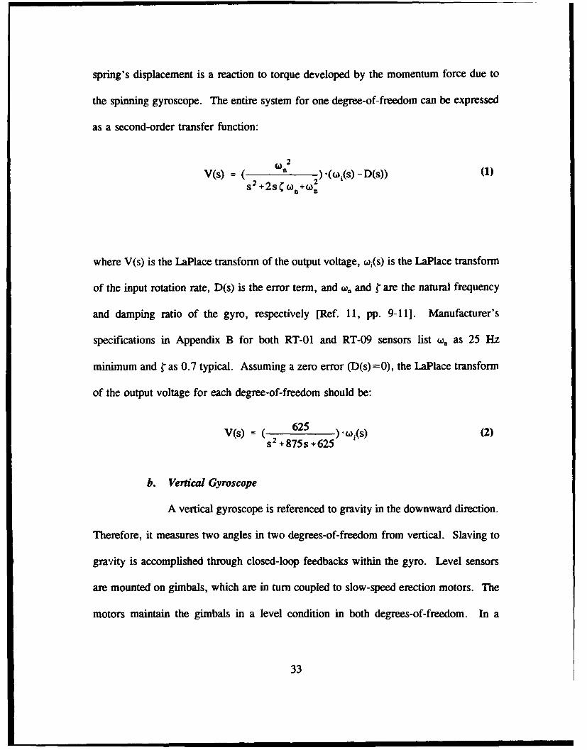
spring's displacement is a reaction to torque developed by the momentum force due to
the spinning gyroscope. The entire system for one degree-of-freedom can be expressed
as a second-order transfer function:
V(s) = ( )(woi(s) - D(s)) (1)s 2 +2s + 2
where V(s) is the LaPlace transform of the output voltage, wi(s) is the LaPlace transform
of the input rotation rate, D(s) is the error term, and w,. and r are the natural frequency
and damping ratio of the gyro, respectively [Ref. 11, pp. 9-11]. Manufacturer's
specifications in Appendix B for both RT-01 and RT-09 sensors list w. as 25 Hz
minimum and " as 0.7 typical. Assuming a zero error (D(s) =0), the LaPlace transform
of the output voltage for each degree-of-freedom should be:
V(s) = (s2 625 ). Oa(s) (2)S +875s +625
b. VeW'cal Gyroscope
A vertical gyroscope is referenced to gravity in the downward direction.
Therefore, it measures two angles in two degrees-of-freedom from vertical. Slaving to
gravity is accomplished through closed-loop feedbacks within the gyro. Level sensors
are mounted on gimbals, which are in turn coupled to slow-speed erection motors. The
motors maintain the gimbals in a level condition in both degrees-of-freedom. In a
33
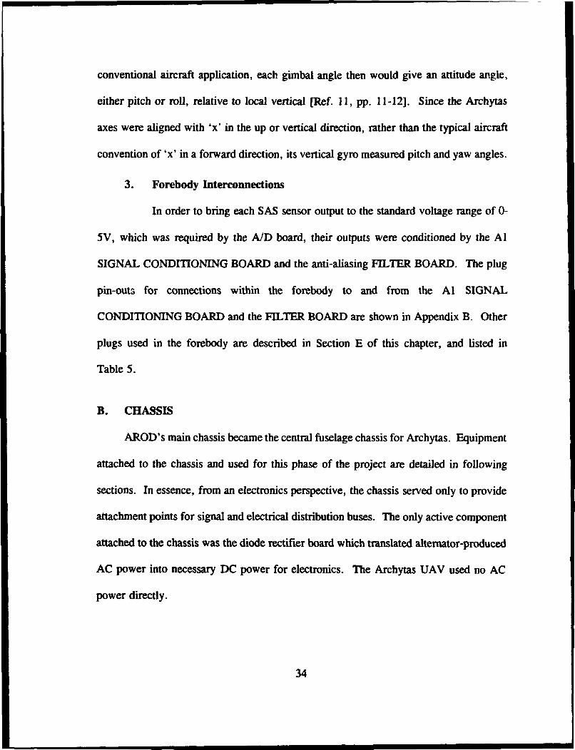
conventional aircraft application, each gimbal angle then would give an attitude angle,
either pitch or roll, relative to local vertical [Ref. 11, pp. 11-12]. Since the Archytas
axes were aligned with 'x' in the up or vertical direction, rather than the typical aircraft
convention of 'x' in a forward direction, its vertical gyro measured pitch and yaw angles.
3. Forebody Interconnections
In order to bring each SAS sensor output to the standard voltage range of 0-
5V, which was required by the AID board, their outputs were conditioned by the A]
SIGNAL CONDITIONING BOARD and the anti-aliasing FILTER BOARD. The plug
pin-outs for connections within the forebody to and from the Al SIGNAL
CONDITIONING BOARD and the FILTER BOARD are shown in Appendix B. Other
plugs used in the forebody are described in Section E of this chapter, and listed in
Table 5.
B. CHASSIS
AROD's main chassis became the central fuselage chassis for Archytas. Equipment
attached to the chassis and used for this phase of the project are detailed in following
sections. In essence, from an electronics perspective, the chassis served only to provide
attachment points for signal and electrical distribution buses. The only active component
attached to the chassis was the diode rectifier board which translated alternator-produced
AC power into necessary DC power for electronics. The Archytas UAV used no AC
power directly.
34

1. Diode Rectifier Board
Electrical power used by Archytas is supplied by either of two sources. The
primary source of power when the vehicle's engine is running is an engine-driven
alternator, to be described in a later section. Alternatively, an external power connection
to a 28V DC power supply is made through the umbilical cord.
The alternator provided 20-50V AC three-phase power, whose voltage varies
proportionally with the engine's RPM. In order to allow either source of power to be
supplied to the vehicle, a diode rectifier board was employed. The board is labeled
"TSB5" on "SHEET 2 OF 2" of the AROD schematic in Appendix C. When external
power was supplied, the diode circuit passed the DC power directly through, but the
power supply was effectively isolated from return surge voltages by the diodes. With
the engine running, the alternator's three-phase AC output is converted to 20-50V DC
by the diode rectifier board. A 1000 4f, 100V electrolytic power capacitor was used to
smooth voltage ripples in the DC output.
The diode rectifier board is also equipped with a circuit which had been used
by AROD as a path for charging the standby battery. This feature was not used in the
Archytas configuration. A photo of the diode rectifier board is shown in Figure 10. A
schematic of the diode rectifier board circuit is shown in Figure 11.
2. Signal Distribution Buses
All signal and electrical connections passing from forebody to rearbody were
connected through distribution buses attached to the exterior of the chassis. A photo of
35

Figure 10 Photo of Chassis-mounted Diode Rectifier Board (TSB5)
36

>
0.
o
, U
"s0
'on
Figure 11 Schvemalic of Diode Reclifier Board (TSB5) with 3-Phase AC lipti!
37

a distribution bus is shown in Figure 12. The buses were labeled TSB# (for terminal
strip board), where # indicates the nearest strut, i.e., TSB2 for the bus mounted next to
strut two. The buses were useful for troubleshooting, as all important signals and
voltages were accessible directly by simply removing the chassis outer shell, without
requiring removal of forebody or rearbody hardware.
3. Engine
As previously mentioned, the Archytas UAV used a Herbrandson Dyad 280
2-cycle engine. The engine is supported by struts from the chassis interior to the
rearbody, as well as by connecting rods running directly from the chassis interior to the
engine. Engine starting was done with a detachable pull cord which wound around a
starting pulley connected to the top of the engine drive shaft. A fuel mixture of 50:1
unleaded gasoline to oil was used. A safety checklist, shown in Appendix D, was
developed for use during engine runs to ensure that proper safety precautions were
followed.
C. REARBODY
The rearbody was supported by four radial support struts which connected to the
chassis' interior. The aerodynamic control vanes were attached to the lower portion of
the rearbody. The umbilical cord was connected to the endcap at the bottom of the
rearbody. The normal endcap designed for use at the end of the rearbody was replaced
by a spare forebody topcap to facilitate secure mounting of the umbilical cord. Figure 13
38

Flpre 12 Photograph of Chassis Bus Board
39

shows the rearbody/chassis assembly, with the control vanes, servos, and umbilical
connection visible in the foreground.
1. Control Vane and Throttle Servos
Standard RC modeling servos were used to control aerodynamic vane
positions and throttle position. The servos were driven by varying the time width of a
0-5 volt pulse from a minimum of 1.0 ms to a maximum of 2.0 ms, with a nominal
midrange of 1.5 ms. PWM servo control is described in Secton d. They were powered
by +5V from a power regulator in the forebody. The term 'servo' is short for
servomechanism or servomotor, which Webster defines as a relatively small, low-
powered device to control a much larger control force [Ref. 13]. In this application, the
servos were small electi.ally-driven motors used to control position of the aircraft's
aerodynamic control vanes, which in turn created much larger aerodynamic forces and
moments. Two different types of servos were used.
a. Futaba Servos
Sandia engineers used Futaba FP-S34 quarter-scale RC modeling servos
for AROD's control vanes. The FP-S34's are constructed of mostly plastic parts,
including the drive-train gears. The throttle servo used was a Futaba FP-S31S. Sandia
engineers chose to obtain servo positions for SAS feedback for AROD by simply tapping
into the servos' internal single-wiper potentiometers [Ref. 8]. It was felt for the
Archytas that such a method could cause interference with the internal feedback circuitry
of the servo. The Futaba servos' lack of ruggedness, coupled with their already being
40

7I
Figure 1.3 Photograph of Rearbody/Chassis Assembly
41

modified with position leads, led to a decision to use new servos for the Archytas control
vanes.
b. Condor Servos
The servos chosen to replace the AROD's Futaba control vane servos
were MS-747WB servos from Consdur RC, Inc. The new servos are constructed with
metal gears, are generally more durable, and provide 50% more torque (167 oz-in for
the Condor MS-747WB versus 112.6 oz-in for the Futaba FP-S34). The MS-747WB
servos are modified with dual-wiper potentiometers to allow for non-interfering electrical
connections for incoming signals and feedback vane position signals. The original
AROD Futaba FP-S31S throttle servo was retained for the Archytas. Throttle position
is deemed not necessary for control feedback at this phase of the project, so no ,ignal
is taken from the servo's potentiometer.
c. Servo Modeling
A second-order Futaba FP-S34 servo model was developed by Merz
[Ref. 2, p. 57] and Davis [Ref. 3, p. 116] by simulating a step input and observing the
servo's response. Their model can be expressed as a second-order transfer function:
C(s) - 2745.8 (3)
R(s) s 2 + 74.1s + 2745.8
where the values of r=0.707 and w,.=52.4 rad/sec were determined experimentally.
Similar tests will need to be done for the Condor MS-747WB servos.
42

d. PWM Servo Control
Command of UAV servos is frequently accomplished through a system
known as pulse-width modulation (PWM). PWM signals are comprised of rectangular
pulse trains. The width of each pulse corresponds to a position command for its
respective servo. The signal can be sent to the aircraft in a variety of ways, such as
through an umbilical cord, as in this phase of the project. In the umbilical method, each
signal has its own dedicated wire. This method of transmission is called parallel data
transmission. Alternatively, the PWM signal may be sent serially by an RF transmitter,
using a method known as time-division multiplexing. The signal may also be generated
aboard the vehicle, as will be required for autonomous flight. Each servo has a circuit
which compares its incoming PWM signal to a reference signal corresponding to its
current position. If there is a difference between the two, the servo's internal motor is
turned to try to drive the difference, or error, to zero.
The nominal, or midrange, pulse width for general purpose RC servos
is 1.5 milliseconds. Full servo movcment in one direction is commanded by a pulse
width maximum of 2.0 ms, while full movement in the opposite direction corresponds
to a pulse width minimum of 1.0 ms. Figure 14 shows a typical PWM signal waveform
with all parameters labeled. The "refresh rate" determines how frequently a new pulse
is sent and/or received. Standard RC servos operate at a refresh rate of about 20 ms (a
frequency of 50 Hz). [Ref. 16]
43

Refresh ,,
D,.' Sh
Rate in ms5 V
a b
a: mnm mpulse width - 1.0 mnsb: nominal, centered pulse width -1.5 insc: maximum pulse width - 2.0 ins
a Minimum pulse width corresponds to fullN - servo deflection in one direction.
- b Centered pulse width corresponds to mid-* range of servo throw.
C Maxirum, pulse width corresponds to full-servo deflection opposite direction.
Figure 14 Typiical PWM Wavcftyriii
44

2. Ignition and Tachometer
Engine ignition spark is provided to each cylinder's spark plug by the solid-
state capacitor discharge ignition (CDI) system, which is housed in the rearbody below
the alternator. A 28V DC-DC converter located in the forebody provided power to the
CDI system. P.lso, a kill switch mounted on the control junction board is connected via
the umbilical cord directly to the ignition leads. The connection is made on chassis bus
board TSB2N
A tachometer signal is provided within the CDI circuitry which could be
monitored during engine operation and displayed on an oscilloscope. The tachometer
signal is generated by a magnetic pickup mounted adjacent to the engine drive shaft
which is exposed to plate spinning with the shaft. The plate has notches in its perimeter
which caused a spike in the pickup's magnetic field as the plate spun past the pickup,
which in turn produces observable pulses on the oscilloscope. The gap from pulse to
pulse represented ms per revolution, so the conversion from ms/rev to RPM is:
RPM = (S X 1 sec X min (4)rev lOOOms 6Osec
3. Alternator
The engine-driven 20-50V three-phase AC alternator is also mounted with the
rearbody. It connected to the engine drive shaft through a bulkhead separating the
rearbody from the chassis. The alternator's three-phase output harness is fed through the
bulkhead and out through a support strut to the outer chassis. There it connected directly
45

to the diode rectifier board (TSB5) and was rectified to DC for distribution to the rest
of the vehicle.
D. VEHICLE INTERCONNECTIONS
Wiring harnesses connected the forebody to the chassis and the chassis to the
rearbody. Surplus AROD harnesses were used wherever possible, as many of the
connections required are the same as had been implemented on the AROD system. The
only new connections not remaining from AROD were those involving the umbilical
cord. The two AROD schematics, which can be found in Appendix C, detail many more
connections than were used on Archytas at this phase of the project. Also included in
Appendix C are schematics showing only those connections which were used in the
Archytas application for this phase of the project. Table 5 defines the connections used
for this thesis referenced to the AROD and Archytas schematics. Plug numbering was
the same as for the AROD system in most cases, as all cables, plugs and sockets on
surplus AROD equipment are well marked and labeled. Differences from the AROD
system are noted in Table 5 as "new", or existing labels have an "N" suffix added to
them. For instance, the new plug for strut three is labeled "PI03N".
In summary, the three sections of the Archytas vehicle each contained hardware
utilized in this thesis. The forebody contains the three sensors, two rate sensors and a
vertical gyro, plus their associated signal conditioning circuits. The chassis is the
mounting location for bus boards which connect signals and voltage supplies from
46

forebody to rearbody. The rearbody houses the alternator, CDI, and servos, and is the
mounting location for the umbilical cord.
Most connecting wiring harnesses were derived from existing surplus AROD
harnesses. New harnesses and bus boards, labeled with an "N", were built to connect
the necessary signals and voltages to the umbilical cord. New plugs and bus boards
which were developed for this work, P21N, PI03N, TSB3N, and TSB2N, have pin
diagrams enclosed in Appendix B. Their physical locations are described in Table 5.
47
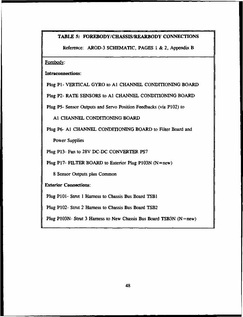
TABLE 5: FOREBODY/CHASSIS/REARBODY CONNECTIONS
Reference: AROD-3 SCHEMATIC, PAGES 1 & 2, Appendix B
Forebody:
Intraconnections:
Plug P1- VERTICAL GYRO to Al CHANNEL CONDITIONING BOARD
Plug P2- RATE SENSORS to Al CHANNEL CONDITIONING BOARD
Plug P5- Sensor Outputs and Servo Position Feedbacks (via P102) to
Al CHANNEL CONDITIONING BOARD
Plug P6- Al CHANNEL CONDITIONING BOARD to Filter Board and
Power Supplies
Plug P13- Fan to 28V DC-DC CONVERTER PS7
Plug P17- FILTER BOARD to Exterior Plug P1O3N (N=new)
8 Sensor Outputs plus Common
Exterior Connections:
Plug P101- Strut 1 Harness to Chassis Bus Board TSB1
Plug P102- Strut 2 Harness to Chassis Bus Board TSB2
Plug P103N- Strut 3 Harness to New Chassis Bus Board TSB3N (N=new)
48

Chassis:
All Chassis Connections were to/from Forebody & Rezabody via Bus Boards
TSB1, TSB2, TSB2N, & TSB3N described above and below with the
exception of direct connections (no plugs) from Diode Rectifier Board
TSB5 to TSB1 (20-50V DC). An additional plug was installed in the
harness from the AC alternator output to the diode rectifier board
(TSB5) for troubleshooting electrical system problems.
Rearbody:
Intraconnections:
Five Servo SignallPower and Feedback Plugs
Umbilical Inner Plug (New)
Exterior Connections:
Plug P200/P202- 5V/Common to Servos and 20-50V 3-Phase AC from Alternator
directly to Diode Rectifier Board TSB5 (AC) and TSBI (5V)
Plug P201- Signals to/from Servos and Electrical Power to CDI Ignition
from Chassis Bus Boards TSB2 and TSB2N (N=new)
Plug P21N- New 21-pin Connector connect TSB2N and TSB3N to Internal
Umbilical 24-pin Cannon Plug Connector (N=new)
Umbilical Cord Exterior 24-pin Cannon Connector (New)
49

V. CONTROL VANE GUIDANCE 'C' ROUnNES
Implementation of control laws to guide the Archytas UAV's control vanes was
accomplished through 'C' routines which controlled the counter/timer and A/D boards.
The evolutionary process which lead up to a routine for hovering flight began with
several simpler intermediate steps. Each new generation of 'C' routine advanced the
system to meet the next requirement. Initially, a system to generate a servo control
signal using PWM was implemented. Then, a method of quickly and reliably
commanding inputs was needed and a joystick was added. Next, a way of providing a
simple feedback using a sensor aboard the vehicle in order to control the vehicle in one
degree-of-freedom was needed, and a roll rate sensor with an uncoupled SISO controller
was added. When the simple SISO feedback system was successfully implemented the
system was advanced to three-axis control. Command inputs for three axes from dual
joysticks were added. To accomplish hovering flight control, more sensory data was
needed, so three-axis rate sensors and a vertical gyro were added to provide data for a
MIMO controller. This introduction describes the current state of the Archytas control
system.
As an introduction, the two routines written by Merz [Ref. 2, Appendices A and B]
to generate PWM signals and control them through an A/D process are summarized in
Section A. Then, Davis' reduced-order SISO controller for roll [Ref. 2, pp. 62-3] was
incorporated via discretized equations. This was done in a routine called roll.c, which
50

is described in Section B. The routine is listed in Appendix A. The final routine,
aiel-ru.c, took input from two joysticks, mixed the commands, then sent separate,
independent signals to each vane. This improvement allowed command of three
aerodynamic surfaces, aileron, elevator, and rudder, through a varying combination of
four control vanes. Section C of this chapter describes how al elnru.c differs from
previous routines, while the routine listing can be found in Appendix A.
A. PWM VANE CONTROL ROUTINES
PWM signal generation was initially accomplished by Merz with a routine called
pwm.c, which used only the counter/timer board. Vane positions were selected by
numeric inputs on the PC keyboard. Next, the A/D process was added in a routine
called atod. c, which took inplts from a single joystick to control the vanes collectively,
so that all four moved in the same direction. This was effectively commanding an
aileron input.- Two routines, both written by Merz [Ref. 2], are summarized. Flow
charts for both pwm.c and atod.c routines are shown in Figures 15 and 16.
1. Basic PWWM Control Using Counter/timer Board
The first Merz routine, pwm.c, uses a counter/timer to generate the pulses
of the PWM signal, controlling both the pulse width and refresh rate. This was done by
loadine numbers into the counter/timer's five counters' load and hold registers,
respectively. The registers are storage locations within the counter/timer's circuitry
which are the heart of the device's operation. The value entered into each counter's load
register controls the pulse width, while the value entered into the hold register controls
51

pwm.c Flowchart
Include "h" functions ] 'C Library Files: defines standard commands
SDeclare Global Variables J Defines Countcr/timem Register Locations
Main function callsSubfunctons
Initialize Counter/timer Board PWM controlled by # to 5 load registers__ Ref"rsh controlled by # to 5 hold registers
I, Cligangle
Entry: Keyboard Commanded Operation:
Vane command desired angles from 70-130Vanes Throttle Throttle command desired angles from 50-130
Aileron PWM 1 PW` Aileron PWM command to vane servos
Command Command Throttle PWM command to throttle aervas
Reference: Quartz and CIO-C'R Counteritimer Manuals
(Written by Paul Menz, Ref. 2, Appendix A)
Figure 15 Flow Chart for pwm.c Routine
52

ato•tcFlowchart
Include .h' functions 'C Library Files: defines standard commands
Declare Global Variables Define Countcr/timer & A/D Regiser Locations
[Main function calls SubfunctionsSL .....ii.....Initialize Counterltimer Board JPWM controlled by # to 5 load registers
Setup A/D Board Refresh controlled by AfD Board counters I & 2
SampleSample A/D Giannels 0-2: ChO- throttle comnd,eOl- aileron comnd, OO2- roll sesor (not in usc)
Single• Joystick
Joystick Left/right: Aileron PWM to vane servos
I Joystick Up/down: Throttle PWM to throttle servo
Refemce: CGO-ADI6jr and DAS-16 A/D Board Manuals
Reference: CIO-CTR and Quartz Board Manuals
(Written by Paul Mem, Ref. 2, Appendix B)
Figure 16 Flow Chart for arod.c Rotifne
53

the interval between pulses. Counters one through four control pulses sent to the four
respective vanes, while counter five controls throttle pulses. Desired commands to the
servos are entered by numerical input from a PC keyboard. Vane commands range from
an "effective joystick angle" of 70 to 130, which represented a -300 to +300 vane
deflection, a span of 600. The term "effective joystick angle" is used since these vane
command values represent actual angles of the stick with respect to horizontal in each
degree-of-freedom. When the vanes are properly adjusted in the servo mounting
brackets, a 100 keyboard command achieves a centered or 0° vane position. Throttle
commands from the keyboard ranged from an effective joystick throttle angle of 50 at
idle to 130 at maximum power, a total span of 800 on the actual joystick. [Ref. 2,
Appendix A]
2. PWM Signal Control Via AID Board
The use of effective joystick angles in pwm. c was in anticipation of the next
generation Merz routine, atod.c, which added sampled actual joystick analog inputs
through the A/D board. Besides the addition of joystick input, a basic difference from
pwm.c was the use of the A/D board's counters to control the PWM refresh rate. The
necessary refresh rate was calculated by Davis to be 10 ms [Ref. 3, p. 55]. This was
implemented through trial and error input of values to the A/D counters until the proper
refresh rate was achieved as observed on an oscilloscope display. The 12-bit A/D board
measured analog inputs from 0 to 5 volts and translated them to a digital value between
0 and 4096 [Ref. 2, Appendix B]. The two degrees-of-freedom available from the
joystick represented throttle inputs (up/down) and aileron commands (left/right).
54

B. SISO ROLL CONTROLLER ROUTINE
Implementation of the reduced-order SISO roll controller model developed by Davis
[Ref. 3, pp. 62-3] consisted of adding the discretized control equations to atod.c. Also,
the necessary adjustments were made to sample another A/D channel for the roll rate
sensor in addition to the two already being sampled for throttle and roll command. The
sampled data were then scaled to a true scale by subtracting the digital value of the
sensor's initial bias voltage. The resulting routine, roll.c, includes the equations
developed by Davis [Ref. 3, pp. 62-3]. A flow chart of the routine is shown in
Figure 17. Appendix A contains the routine listing for roll.c, including explanatory
comments. Modifications to Merz' atod.c routine which are included in roll.c are:
"* Within the "sample" function, control of the A/D conversion process ispassed from external-triggering to software-triggering during the continuousloop to allow for the sequential sampling of multiple channels;
"* The "sample" function includes discretized equations for the reduced-ordercontrol model, utilizing a lookup table to assign proper values to the vaneservos;
"* Software limiting is used in the "sample" function to prevent vane angles past300, which would result in vane stall, by assigning a constant vane commandwhen the vanes reach 30°;
"* A "senbias" function samples the roll rate sensor input 10 times, thenaverages, before initiation of routine loop; calculated average bias is thensubtracted from every roll rate sample.
C. MIXED CONTROL SURFACE GUIDANCE ROUTINE
The use of two joysticks is required for control of all three aerodynamic control
surfaces and throttle. Commands to the four vanes needed to be mixed so that the three
control functions could be achieved using the same four vanes. As previously mentioned
55

roll.c Flowchart
Include ".h" functi(onq "C Library Fils: dcfines standard commands
Declare Global Variables Defime Counter/Limer & A/D Register Locations
Main function calls Subftuctions]
Initialize Courter/mer Board 1 PWM controlled by # to 5 load registers
F Setup A/I) Boa1 Refresh controlled by A/D Board counters I & 2
F Senbias 1 Samples roll rate sensor 10 times and averages______to determine sensor bias
-. ~~Sample AID Carmnels 0-2: CWO thotle comud,Sample Chai- aileron cormnd, 0~2- roll sensor input
- ~ l - - JIncludes SISO controller- joystick cmnnd is combinedSlnglel Joystick with sensor input minus bias to determine PWM value
(ligangle Joystick Leftrght: Aileron PWM to vane servonCounters 1-4
e Joystick Up/down: Tirottc PWM to throttle servoSample/tl"Dcounter 5
Reference: CIO-AD16jr and DAS-16 A/D Board ManuReference: CIO-CR and Quartz Board Manuals
(Written by Paul Menz & Pat Morm)(SISO Control Equations by Joe Davis)
Figure 17 Flow Chart for whoiiu Routiie
56

in Chapter MTT, vanes one and three represent the upper and lower rudder, vanes two and
four the left and right elevator, and a combination of all four vanes represent the aileron.
The equations to translate three joystick degrees-of-freedom into four vane commands is:
vane I = (aileron . rudder)4 2
aileron elevatorvane 2 =( +4 2~ (5)
vane 3 aileron rudder)4 2
vane 4 (aileron elevator)4 2
where vanes 1-4 represent the values sent to the counter/timer to determine each vane
servo's pulse width, and aileron, rudder, and elevator represent the commands input
through each of the three respective joystick degrees-of-freedom. The factors of '/z and
'A arise from the fact that elevator and rudder commands are split between two vanes
each, while aileron commands must be split among all four vanes. This algorithm,
developed by Kaltenberger [Ref. 14], accomplished the necessary mixing of aileron,
elevator, and rudder inputs to allow four independent vane positions to be commanded.
Several trial and error loops were required to determine proper multiplicative and
additive factors to apply to the A/D digitized values to achieve the proper vane deflection
angles for a given joystick input while keeping the vane servos properly aligned. The
factors applied to each channel, from the sample function in ai0el/ru. c, are:
throttle = (channelO- 2714)- 0.12 + 80aileron = (channell - 1600) - 0.4 +2200 (6)elevator = (channel2 - 1850)- 0.2 - 80rudder = (channel3 - 720) - 0.2 - 80
57

This system was implemented in ai el/ru.c which is listed in Appendix A. A flow
chart of aielru.c is shown in Figure 18. Improvements written into ai"el ru.c over
previous generation routines include:
"S The use of 'C' language "prototypes" to pass variables from function tofunction, and to specify to the compiler what each function expects as inputsand outputs. [Ref. 18]
"* Use of arrays to minimize repetition of similar sequences and improve speed.Arrays in 'C' are indexed starting at '0', which agreed with the A/D board'sconvention of numbering channels starting with Channel 0. [Ref. 181
"* Reduced sampling period from the 10 ms rate used in previous routines to25 ms, in anticipation of additional computing time necessary for the morecalculation-intensive MIMO control law implementation. This was done byincreasing the numbers assigned to the A/D board's counters in the "setup"function, as commented in the routine listing in Appendix A.
In summary, two routines have been written to accomplish specific tasks which
built upon each other. These routines were based upon PWM and A/D routines written
by Merz [Ref. 2]. The first routine (roll. c) used PWM signals commanded from a single
joystick and a SISO controller to control single-axis roll. The second is a routine
(ai el ru.c) to command the PWM signal using dual joysticks to biend three joystick
inputs into four independent vane commands.
58

aLeL.ru.c flowdbazt
Include ".h" functions 'C Library Files: defines standard commands
Declare Global Variables Define Cointer/timer & A/D Register Locations
Prototypes Prototype each function's Input & output for compiler
Main function calls Subfunctions
Initialize Counter/timer Board PWM controlled by # to 5 load registers
- Refresh controlled by A/D Board countem I & 2Setup A/D Board Refrh rate reduced to 25 nm from previous 10 ins
________ - Salmle A/D Channels 0-3: QiO- throtle,IampCe I- aileron, 012- elevator, C03- rudder
ail Joysticks Arrays used to Index chanls through A/D loopLA-kvck Rik atc
Cigangle Left/Right rudder aileron
Up/Dow thottle elevator
Reference: CIO-AD160r and DAS-16 AID Board Manuals
Reference: CIO-CTR and Quartz Board Manuals
(Written by Pat Moran, Basic PWM & A/D Sampl! ng by Paul Mer)
Figure 18 Flow Chart for ai el ru.c Routine
59

VI. SYSTEM EVALUATION AND RESULTS
As with any developmental system, evaluation of the system is not complete until
the design has been validated by appropriate testing. This chapter details the tests done
to evaluate the Archytas UAV control system algorithms, vehicle, and ground control
hardware designs. Results are presented for each phase of work. Conclusions drawn
from the results and recommendations for improving the system based on the results are
presented in the following chapter.
A. VEHICLE AND GROUND CONTROL EQUIPMENT EVALUATION
The hardware results of this thesis fall into the categories of ground control and
vehicle equipment. Ground Control Equipment development is described in Chapter IMI,
while On-board Vehicle Equipment design is discussed in Chapter IV. Evaluation of the
hardware in each area is described in the following sections.
1. Ground Control Equipment
The design of ground control equipment consisted of expanding the existing
system to accommodate the additional require.:ents of the MIMO controller, which
reqtired more signal capacity through the umbilical cord for the additional sensors. A
new umbilical cord was required and was added to the control junction board with an
additional connection bus. The control junction board was modified to provide for dual
joystick pilot command, and to allow for remote connection of the external DC power
supply. The A/D board connections were expanded to allow for the sampling of the 12
60

channels necessary for MIMO control. When all wiring connections were accomplished,
each signal line was checked to ensure electrical continuity. The joysticks were verified
to work over their full range, as given in Table 3 in Chapter III. A new 486 PC was
configured and used for generation of routines and lab testing of control systems,
providing dual-site PC operating capability.
The counter/timer and A/D boards were tested using software provided from
their manufacturers which exercised their circuitry to determine proper installation in the
PC. Their operation was also validated by observation of the expected PWM outputs
from PWM routines when displayed on an oscilloscope display.
2. On-board Vehicle Equipment
Accomplishments in the area of On-board Vehicle Equipment consisted of
reconfiguration of the sensor pod from its previous rearbody location to the AROD-style
forebody location. Surplus AROD harnesses were installed for the dual-axis rate sensor,
the vertical gyroscope, and three-axis accelerometers (although not yet used in this phase
of the project). The wiring of new Al Channel Conditioning Board, Filter Board and
signal output plugs was also completed.
The chassis was reconfigured using AROD bus boards and new umbilical
chassis bus boards. The AC power supply diode rectifier board was relocated from the
sensor pod to the chassis exterior. New wiring harnesses to and from the umbilical were
constructed. The rearbody AROD servo wiring harness was used in its entirety.
Additional rearbody umbilical-related harnesses and plugs were constructed.
61
Again, when all vehicle wiring connections had been accomplished, all signal
wires were checked for proper electrical continuity from the vehicle to the control
junction board through the umbilical cord. The use of chassis bus boards, which were
accessible easily on the exterior of the chassis, greatly improved the ease with which
signal flow could be traced.
While conducting engine runs to determine vehicle characteristics, the +5V
voltage regulators mounted in the forebody which supply 5V servo power were tested.
On two occasions, the 5V regulators burned out. It is believed that high engine RPM
during testing drove a higher than expected voltage output from the alternator, which in
turn supplied too high a voltage to the regulator. Since excess voltage to the regulator
is dissipated through heat discharge, if more voltage is supplied than can be dissipated,
the regulator fails. A temporary fix was installed, which consisted of adding resistors
in series with the input to the +5V regulator to reduce the voltage potential being
supplied to the regulator. The resistors also failed later during engine runs. Subsequent
testing was done only on external power. Recommendations in Chapter IV include
resolving this problem.
The alternator and ignition systems were tested during engine runs. The
vehicle operated normally when the external DC power supply was removed, indicating
proper operation of the alternator. No specific observations were made of the three-
phase output from the AC alternator, such as voltage for a given engine RPM. The
ignition system operated adequately for engine operation, but was also not specifically
observed. The CDI tachometer output was used to determine engine RPM, as given by
62

Equation 4 in Chapter IV. Tachometer speeds were verified using a Futaba transmitter's
RPM meter, which measured engine RPM through a photo-optic sensor which sensed
propeller speed.
Severe vehicle vibration was apparent during all engine operations with the
sensor pod mounted in the rearbody position, causing numerous component failures. The
engine was not run after the sensor pod was relocated to the forebody position. To
prevent future vibration-related problems, rubber grommets were used in hardware
connections whenever possible to dampen vibrations. All electrical connections were
converted to sturdy plugs held together by nuts and bolts to prevent vibration-induced
disconnections.
The sensor outputs from the vertical gyroscope and two rate sensors were
tested in the lab using Personal VISSIM, Version 2, a software program capable of
displaying analog signals in real time through another AID board mounted in the 486
computer. Digitized graphs of the analog sensor outputs, resembling oscilloscope
displays, were used to simultaneously observe all five sensor outputs at once. Simulated
vehicle movements were achieved by holding the forebody sensor pod independent of the
vehicle and moving it in the desired direction. Both vertical angle signals varied linearly
with the angle of inclination of the sensor pod as it was inclined in each axis. Roll,
pitch, and yaw rate signals varied in magnitude with the rate at which the pod was
rotated in each respective axis. Sensor outputs through the forebody Al Channel
Conditioning and Filter Boards were verified by observing the proper 0-5V ranges from
each sensor output with a voltmeter.
63

The servos which guide the control vanes and throttle were observed to
exhibit noticeable chatter when operated at the 10 ms refresh rate used by Merz and
Davis. Reducing the refresh rate to 25 ms reduced the chatter significantly. The use of
commercially available noise suppressors also helped minimize chatter. The noise
suppressors operate through an 74LS04N hex inverter microchip, which inverts each
PWM signal, then reinverts the signal. The original PWM signal is retained, but noise
is suppressed by the double inversion process.
B. CONTROL ROUTINE EVALUATION
Evaluation of the PWM and A/D vane control system consisted of commanding
inputs to the control vanes via joysticks and observing the deflection responses of the
vanes and throttle to ensure that they remained within the vane stall limits of 300 for the
vanes and within the engine throttle linkage limit for the throttle. This was done first
with a single joystick, commanding throttle and ailerons, then with dual joysticks
commanding throttle, ailerons, elevator, and rudder. SISO control law implementations
were tested by simulating vehicle motions, thereby upsetting the installed sensors, and
observing the vane counteraction responses. MIMO control laws were written into a
routine, with testing accomplished and documented by Kaltenberger [Ref. 14].
Merz' basic PWM and A/D conversion programs [Ref. 2] were tested in the lab
on a stationary vehicle. The next step in complexity, implemented in roll.c, involved
addition of the SISO roll control. This led to testing with the engine running. A roll
disturbance was simulated by upsetting the vehicle with a rolling force. The vane
64

deflection response observations were purely qualitative in that the vanes responded in
the proper direction to counter the disturbance. However, no analysis was conducted to
determine if the amount of vane deflection was appropriate for the given disturbance.
Implementation of the dual joystick vane control program, ai_elru.c, was again
tested primarily in the lab. Evaluation involved observation of vane deflection responses
from commanded inputs from both joysticks. Again, the vane deflections and the throttle
linkage remained within linear limits.
1. Implementation of SISO Controller
The simplified roll rate controller developed by Davis [Ref. 3] was tested
with the vehicle engine running while mounted in a rigid test stand. The system
satisfactorily commanded the proper direction aileron vane deflections to counteract
simulated roll disturbances, although the tests were only qualitative and not fully
conclusive since no analytical data on the degree of deflection for a given disturbance
could be obtained due to the limits of the test stand. Joystick roll command was operable
allowing input of a slow operator-commanded rolling motions within the limits of the test
stand (about one full turn of the vehicle).
A problem which arose during testing of the roll controller implementation
was the inability of the controller to recognize when the vanes had reached their
aerodynamic effective limit of 30* deflection. A simple solution was added which
stopped the aileron vane deflection when it reached 30', which is the limit of deflection
where stall is expected to occur, even if the joystick continued to command an increasing
roll. This was done by freezing the PWM command to the vanes when the limit was
65

reached. The controller, however, continued to integrate the difference between the
joystick command and the roll rate sensor input, thereby calculating an increasingly
greater deflection command. The effect is known as controller windup. It can be
resolved by adding an antiwindup algorithm to the controller to limit the controller from
calculating commands larger than the limit of the device it is controlling. [Ref. 19]
2. Dual Joystick Control Vane Guidance
Control of the four vanes using mixed input from dual joysticks was
accomplished. Vane deflections were controllable from both joysticks throughout the
±300 range of each vane, providing a full range of control for each aerodynamic control
surface. The equations used to implement vane mixing and the factors applied to each
digitized channel are provided in Equations (5) and (6) in Chapter V. Slowing the
refresh rate from 10 ms to 25 ms in aielru.c improved the steadiness of the servo
responses. Through discussions with a Futaba representative, it was determined that the
faster refresh rate was driving the servos faster than they were designed to react. Futaba
FP-S34 servos are designed to operate on a 20 ms refresh rate. [Ref. 15]
C. SUMMARY OF RESULTS
Ground control equipment was expanded from the previous design to allow for the
greater signal capacity required by the MIMO controller. The vehicle was redesigned
to a forebody-mounted sensor pod, due primarily to excessive vibration observed during
engine runs. Center of gravity requirements for forward flight stability also were
improved by moving the pod forward. Voltage regulators failed during engine runs,
66

which resulted in loss of power to the servos. A temporary solution was installed, but
it too was ineffective.
Implementation of the SISO controller was accomplished and tested in conjunction
with the work of Merz and Davis. The SISO controller reached a limit when the vanes
were commanded by joystick to their maximum angle, which resulted in vane position
being fixed at that position until the controller was commanded back into its region of
authority. This problem may be rectified by adding an antiwindup algorithm to the
controller, as discussed previously.
Dual joystick-commanded control of three aerodynamic control surfaces through
four control vanes was achieved. Array indexing and 'C' language prototypes were
implemented to improve software efficiency. Servo chatter was reduced by slowing the
PWM signal refresh rate from 10 ms to 25 ms.
67

VII. CONCLUSIONS AND RECOMMENDATIONS
This thesis began under the assumption that the rear-mounted sensor pod design
previously implemented by Merz [Ref. 2] would be suitable for the Archytas UAV.
However, it became obvious, after several engine runs during testing to acquire
aerodynamic data about the vehicle, that the vibration generated by the vehicle's two-
stroke engine was more than the rear-mounted sensor pod design could withstand. This,
combined with further stability calculations by Stoney [Ref. 9], led to a decision to move
the sensor pod to the forebody location. The focus of this thesis became reconfiguration
of the ground control equipment including the umbilical cord and associated control
junction board, and redesign of the vehicle to a forebody-mounted sensor pod.
Much awareness was gained in the area of real-world electrical system design. The
impact of such things as floating grounds, noise interference, and signal crosstalk became
apparent when they impacted system design and testing. What at first seemed to be a
simple requirement to "move the pod forward", became a much larger requirement to
resurrect surplus AROD harnesses and reverse-engineer the AROD system design. A
frequent question became "Why did they do that?", which usually lead to more research
through old AROD documentation and schematics. Also, unexpected airframe design
considerations impacted the design of several electrical components involved with this
thesis, such as wiring harness paths which had to be moved to allow for mounting of the
wing spars.
68
An "antiwindup" scheme should be added within the controller equation loop,
which would prevent the integral controller from continuing to integrate the errors after
the 300 vane software limit has been reached. This would prevent the controller from
continuing to calculate corrections after the vanes had reached their aerodynamic stall
limits. [Ref. 19]
All equipment should be mounted using vibration damping techniques and fixtures.
Before actual flight test of the vehicle, all hardware should be secured using LokTite, or
a similar product which will prevent screws and nuts from backing off due to vibration.
The three-phase output of the AC alternator should be measured during engine
operation to determine AC voltage ranges and volts/RPM. Investigation should be done
toward the replacement of the AC alternator system with DC battery power, which could
lead to a reduction in vehicle weight, as suggested by Hoffman [Ref. 17]. A full power
budget will be required to determine complete present and future system power
requirements.
The forebody +5V DC power regulators which supply servo power should be
redesigned so that they will not fail when the engine runs at high speeds. This problem
could be rectified by replacement of the engine-driven AC alternator with DC batteries.
The hovering flight MIMO control equations developed by Kaltenberger [Ref. 14]
were formatted for computer implementation. The MIMO program design needs to be
completed, then tested using a simulated model of the Archytas UAV fed by feedback
of model outputs.
69

APPENDIX A: 'C' PROGRAMS DEVELOPED FOR THE ARCHYTAS UAV
/* ROLL.C *// ************/
/* Written by Paul Merz & Pat Moran, Oct 92 *1/* Uses Counter/timer & A/D boards *//* Implements Roll rate control using Joe Davis' simplified controller. *//* Input comes from joystick or roll sensor to guide 4 vanes together. *//* Throttle controlled from joystick. PM 4/27/93
#include < dos. h >#include < stdio. h >#include < time. h >
mt datreg = 544; /* Ctr/timer board, base addressmt conreg = 545; /* Ctr/timer board, base addr + 1int basaddr=768; /* A/D board, base addressmt basepll =769; /* A/D board, base addr + 1mt mux=770; /* A/D board, base addr +2 */mt statreg=776; /* A/D board, base addr +8 */mt intcont=777; /* A/D board, base addr +9 */mt pclock=778; /* A/D board, base addr +10mt inrange=779; /* A/D board, base addr +11 *mt cntrl=781; /* A/D board, base addr +13 */mt cntr2=782; /* A/D board, base addr +14mt cntrcon=783; /* A/D board, base addr +15float ts = .010;float ki = .004376; /* # controls rate of response to stick mvmnt, */float kI = -.2027; /* .004376 gives slow roll, .04 gives quick roll */int lookup[70],newangle,throttle,bias; /* Global variables
maino{initialize0;setupo;throttle = 51;chthrottleo;
70

senbiaso;sampleo;
initialize() /* This function is thoroughly commentedby Merz [Ref. 2, Appendix A] *
int cmnd,i;cmnd =255; /* reset allI board functions *outportb(conreg ,cmnd);cmnd=23; /* select master mode registeroutportb(conreg ,cmnd);cmnd = 176; /* low byte enables fout *outportb(datreg ,cmnd);
cmnd =65;
outportb(datreg ,cmnd);cmnd = 249;outportb(conreg ,cmnd);for (i=1I;i < =5;i+ +)
cmnd=i; /* Select group 1-5 *outportb(conreg ,cmnd);cmnd=2; /* Low byte set ctr 1-5 mode in CMR ~outportb(datreg,cmnd);cmnd=27; /* High byte: no gating for ctr 1-5 *outportb(datreg ,cmnd);
for (i=25;i< =29;i++)
cmnd=i; 1* Load hold register for refresh rateoutportb(conreg,cmnd);cmnd=0;outportb(datreg,cmnd);cmnd = 10;outportb(datreg,cmnd);
for (i =9;i < = 13;i ++)
cmnd=i; /* Select load register for pulse width *outportb(conreg ,cmnd);cmnd= 110; /* Load low byte into load register *outportb(datreg ,cmnd);cmnd =5;
71

outportb(datreg,cmnd);
for (i=233;i < =237;i+ +)
cmnd =i;outportb(conreg,cmnd);
cmnd = 127; /* Load and arn ctr 1-5outportb(conreg,cmnd);for (i =1;i < = 70; i+ +) lookup[i] =50 +i;printf("COMPLETED INITIAUJZATION OF SERVOS\n");
setup() /* This function is thoroughly commentedby Mer-z [Ref. 2, Appendix A] *
int cmnd;cmnd=0; /* Set the mux to read channels 0-2outportb(mux,cmnd);cmnd =2; /* Set up pacer clock for clock driven-s-ampling *
outportb(~pclock,cmnd);cmnd=5; /* Set up for correct input & type of voltageoutportb(inrange,cmnd);cmnd = 118; /* This selects control reg for mode & ctr 1outportb(cntrcon,cmnd);cmnd = 100; /* Load up counter one of pacer clockoutportb(cntrl ,cmnd);cmnd =0;outportb(cntrl ,cmnd);cmnd = 182; /* Selects control reg for mode & ctr 2outportb(cntrcon,cmnd);cmnd= 100; /* Load ctr 2 of pacer clockoutportb(cntr2 ,cmnd);cmnd =0;outp~ortb(cntr2 ,cmnnd);printf(" COMPLETED CARD WINILALIZATION\n");
72

senbias0 /* This function samples the roll rate sensorinput 10 times to determine an average sensorbias prior to entering the A/D sampling loop. */
int x,lsb,msb,tsb,sreg;x=O; bias=0; /" Set counter and initial bias to 0 *1
while (x < =10) /* Count 10 times through bias loop{sreg=inportb(statreg); P" Check int bit of status reg for highsreg=sreg & 16; /* indicating start of new refresh cycle.if (sreg= =16){
lsb=inportb(basaddr); /* Read in lobyte */msb=inportb(basepll); /* Read in hibyte */lsb=lsb > > 4; /* Roll lower 4 bits rightmsb=msb < < 4; /* Roll upper 4 bits left */tsb=msbIlsb; /* Jitwise 'OR'bias=tsb + bias; /* Maintain cumulative sum */x=x+1; /* Increment loop counter */}
}bias = bias / x; /* Aerage bias by # of times thru loopbias = 2048 - bias; /* 2048 is center of A/D range, so biasprintf(" bias = %d \n",bias); /* will be above or below center */printf("hit any key to start: "); /* Wait for operator start */scanf(" %d",&x); /* Read in start (any #) */
sampleo{int x,cmnd,lsb,lsbl,lsb2,lsb3,sreg;float xlk,epinkl,epink,epk,ulk,pk;
x=1; epink = 0; /* Set loop counter to 0; Set initial values */pk=O; /* of error increment & roll increment =0while (x= =1) /* Infinite loop{sreg=inportb(statreg); /* Check int bit of status reg for ni, indicating */sreg=sreg & 16; /* pacer clock has triggered new refresh cycle */if (sreg= = 16) /* When int=hi, enter A/D loop */{
cmnd=32; /* Set mux to count Ch 0-2 */outportb(mux,cmnd);cmnd =0;
73

outportb(intcont,cmnd); /* SOFTWARE TRIGGERED A/D ONLY */outportb(basaddr,cmnd); /* IMMEDIATE A/D CONVERSION */lsb = inportb(basaddr); /* Read in lobyte, MSB-8 to LSB+CHAN */Isbi = inportb(basepll); /* Read in hibyte */lsb = lsb > > 4; /* Roll lower 4 bits rightlsbl lsbl < < 4; /* Roll upper 4 bits leftlsbl = lsbl I lsb; /* Bitwise 'OR'outportb(basaddr,cmnd); /* IMMEDIATE A/D CONVERSSION */lsb = inportb(basaddr); /* READ LOW BYTE, MSB-8 TO LSB+CHAN*/lsb2 inportb(basepll); /* READ HIGH BYTE, MSB TO MSB-7 */lsb =lsb > > 4; /* ROLL LSBYTE RIGHT 4 BITSlsb2 = lsb2 < < 4; /* ROLL MSBYTE LEFT 4 BITSlsb2 lsb2 I lsb; /* 'OR' TO GET 12 BIT INFOoutportb(basaddr,cmnd); /* IMMEDIATE A/D CONVERSION */lsb = inportb(basaddr); /* READ LOW BYTE, MSB-8 TO LSB+CHAN*/lsb3 = inportb(basepll); /* READ HIGH BYTE, MSB TO MSB-7 */lsb = lsb > > 4; /* ROLL LSBYTE RIGHT 4 BITS */lsb3 = lsb3 < < 4; /* ROLL MSBYTE LEFT 4 BITSlsb3 = lsb3 I lsb; /* 'OR' TO GET 12 BIT INFOcmnd=2;outportb(intcont,cmnd); /* RTN PACER CLCK-DRIVEN SAMPLING*/cmnd =inportb(statreg); /* Read status reg, then write backoutportb(statreg,cmnd); /* to status reg- causes flip-flop reset */xlk = ((isbl +bias)-2048) * .048828; /* Convrsion fm dig to rad of 'pcommand'-/pk = (1sb3-1033) * .0351; /* Read in current value of 'p' or roll rate */epk = pk - xlk; /* Tracking Error= 'p' - 'pcommand' /Iepinkl = epink + epk; /* Sum cumulative errors */ulk = ((-1 * ki) * epinkl) - (kl * xlk); /* Davis' Eqn. 4.19, Ref. 3, p. 63 */epink = epinki; /* Increment Ercoi term */newangle=(int)(ulk + 35); /* Truncate cominand, add normalizing factor */if (newtngle < 1) newangle = 1; /* Software limit to keep total */if (newangle > 69) newangle = 69; /* vane deflectn below +/-30 deg */newangle=lookup[newangle]; /* Keeps vane deflctn in +/-30 range */chgangleo; /* Call change angle routine */throttle = (int)((lsb2-2714) * .15 + 65); /* Throttle cmnd normalizing */chthrottleo; /* Call change throttle routine */
}
chgangle0 /* CHANGES VANES VIA CONTROL EQNS, CALLED FM .sampleo*/{int i, hibyte,lobyte,angle,cmnd;
74

angle= ((1900/206)*newangle +600); 1* Algorithm to convrt fm deg to dig # *hibyte =(angle/256); /* Hibyte formed, residue remaining for lobyte ~1obyte=(angle-hibyte*256); /* Lobyte fromed from remaining residue *
cmnd =207; /* Disarms ctrs 1-4 for loading *outportb(conreg,cmnd); /* Sends to control reg *for (i =9; i < = 12;i + +) /* Selects load reg for pulse width of ctrs 1-4 *
outportb(conreg,i); /* Loads lobyte, then hibyte into each ctr ~outportb(datreg, lobyte);outportb(datreg ,hibyte);
for (i = 233;i < = 236;i+ +) outportb(conreg,i); /* Sets toggle high for ctr 1-4 *
cmnd=lIl1; /* Load and arm ctrs 1-4outportb(conreg ,cmnd);
chthrottle() /* CHANGES THROTTLE, CALLED FROM sample()o
int i, hibyte, lobyte, angle, cmnd; 1* This routine is samc as CHGANGLE ~cmnd =208; 1* except it changes only ctr 5 *
outportb(conreg,cmnd); /* for throttleangle = ((1900/206) *throttle + 600);hibyte =(angle/256);lobyte = (angle-hibyte*25 6);cmnd = 13;outportb(conreg,cmnd);outportb(datreg,lobyte);outportb(datreg, hibyte);cmnd =237;outportb(conreg,cmnd);cmnd = 112;outportb(conreg ,cmnd);
75

/* Al EL RU.C, ARCHYTAS UAV PROJECT, NPS MONTEREY *
/* Written by LCDR Pat Moran 5/14/93/* Basic PWM routine by LT Paul Merz [Ref. 2, App A & BI/* Demo to move aileron, rudder, elevator, & throttle/* from 2 joysticks. Blends 3 degrees-of-freedom into *//* 4 independent vane commands./* With assistance from Chris Miller NPS EE Dept; Isaac/* Kaminer/Burke Kaltenberger for mixing algorithm.
#include < dos. h >#include <stdio.h>#include <conio.h> /* Only used by 'clrscr' command
int datreg = 544; /* Ctr/tirner board, base addressint conreg = 545; /* Ctr/timer board, base addr + 1int basaddr=768; /* A/D board, base addressint baseplI =769; /* A/D board, base addr + 1mt mux=770; /* A/D board, base addr +2mt statreg=776; /* A/D board, base addr +8mt intcont=777; /* AD board, base addr +9int pclock=778; /* AID board, base addr +10mt inrange=779; /* A/D board, base addr + 11mt crtrl =781; /* AID board, base addr +13int cntr2=782; /* A/D board, base addr +14int cntrcon=783; /* A/D board, base addr +15
void main(void); /* Prototypes: */void initialize(void); /* prototyping functions- tells compiler */void setup(void); /* what goes into and out of each function */void sample(void); /* i.e. int sample(void) means integer inputvoid chgangle(int,int,int,int); /* and no or 'void' output */
void main(void){initializeO;setupo; !* Main function calls all others */sampleo;
76

void initialize(void) /* Initilizes cntr/timer board{
int i;clrscro; /* Clears screen for display */outportb(conreg,255); /* Reset all board functions *1outportb(conreg,23); /* Select master mode register */outportb(datreg,176); /* Lobyte enables FOUT, F1 source */outportb(datreg,65); /* Hibyte selects binary division */
/* disable incr, 8bit bus, FOUT on/* divide by 1. */
outportb(conreg,249); /* Disable prefetch for write opsfor (i=l;i< =5;i++){outportb(conreg,i); /* Select ctrs 1-5 */outportb(datreg,2); /* Lobyte: set modes ctrs 1-5 in CMR */outportb(datreg,27);/* Hibyte: no gating for ctrs 1-5 *1}
for (i=25;i< =29;i++){outportb(conreg,i); /* Load hold registers for refresh rate */outportb(datreg,0); /* Ctrl reg+Ctr2 reg= Refresh Rate */outportb(datreg,10);/* This combo = 25 ms rate (40 Hz) */}
for (i=9;i< =13;i++){outportb(conreg,i); /* Select load registers for pulse width */outportb(datreg,1 10); /* Sets time for next pulse */outportb(datreg,5);}
for (i =233;i < =237;i+ +) outportb(conreg,i);outportb(conreg,127); /* Load & arm ctrs 1-5 *1printf("\n\n\n *** COMPLETED COUNTER/TIMER INITIALIZATION ***\n");
void setup(void) /* Initializes A/D board */{
outportb(mux,48); /* Sets mux to read chan 0-3 */outportb(intcont,2); /* Sets pacer for clock-driven sampling */outportb(inrange,5); /* Sets for input voltage range: 0-5V */
/* Fm data sheet: SC-01, RW-11, M-011, BCD-0 */outportb(cntrcon, l18);/* Ctr 1, READ/WR Isbyte IST, mode 3, binary *1outportb(cntrl,100); /* Load ctr 1 lower byte *1outportb(cntrl,0); /* Load ctr 1 upper byte */
77

/* Fm data sheet: SC-10, RW-11, M-01 1, BCD-0 */outportb(cntrcon,182);/* Ctr 2, READ/WR Isbyte IST, mode 3, binary */outportb(cntr2,250); /* Load ctr 2 lower byteoutportb(cntr2,0); /* Load ctr 2 upper byte
/* Ctrs l&2 combo sets sampling period: 25ms *1printf(" *** COMPLETED A/D BOARD INITIALIZATION ***\n");
void sample(void) /* Samples channels via A/D board{
int x,i,cmnd,lsb,msb,sreg,elev,rud,ail,thr,ch[4];x=l;
while (x= =) /* Endless loop */{sreg=inportb(statreg);/* Read stat reg to check intrpt bitsreg=sreg&16; /* 'AND' with 16 to get only 5th bitif (sreg=- 16) /* If intrpt (5th) hi, pulse rcvd */{
outportb(mux,48); /* Read Channels 0-3 */outportb(intcont,O); /* Software triggered A/D only */for (i=O;i< =3;i+ +) /* Read ChO-3 for thr,ail,elev,rud */{outportb(basaddr,O); /* Immediate A/D conversion */lsb = inportb(basaddr); /* Read lobyte, MSB-8 to LSB + Chan /msb = inportb(basepll); /* Read hibyte, MSB to MSB-7lsb = lsb > > 4; /* Roll Isbyte right 4 bits */msb = msb < < 4; /* Roll msbyte left 4 bits */ch[i] = msb I lsb; /* 'OR' to get 12 bit info */
outportb(intcont,2); /* Return to pacer clock-driven sampling */cmnd-=inportb(statreg); /* Read status reg, then write back to */outportb(statreg,cmnd); /* status reg: resets Pin25 flip-flop */thr = (int)((ch[O]-2714)*.12+80); /* Input fm throttle up/down */ail = (int)((ch[1]-1600)*.4+200); /* Input fm aileron It/rtelev = (int)((ch[21-1850)*.2-80); /* Input fin elevator up/down *1rud = (int)((ch[3]-720)*.2-80); /* Input fm rudder lt/rt */chgangle(thr, ail, elev, rud); /* Call chgangle function */
}}
78

void chgangle(thr, ail, elev, rud) /* Uses counter/timer to calculate */{ /* each pulse width */
int i,hibyte,lobyte,angle,vane[51;vane[O] = ail/4 + rud/2; /* VI; Translation algorithm fm 3 */
vane[l] = ail/4 + elev/2; /* V2; control surfaces to 4 vanes */
vane[21 = ail/4 - rud/2; /* V3; */vane[3] = ail/4 - elev/2; /* V4; */
vane[4] = thr; /* Throttle needs no conversion */
outportb(conreg,223); /* Disarm counters 1-5for (i=O;i< =4;i++)
angle=((1900/206)*(vane[i])+ 6 0 0 ); /* Convert fm deg to dig # *1
hibyte-=-(angle/256); /* Calc high byte, residue left */
lobyte-=-(angle-hibyte*256); /* Calc low byte fm residue
outportb(conreg,(i+9)); /* Load counters 1-5 */
outportb(datreg,lobyte); /* Load low byte */outportb(datreg,hibyte); /* Load high byte *1
}for (i=233;i< =237;i++) outportb(conreg,i); /* Set toggle hi 1-5 */
outportb(conreg, 127); /* Load & arm counters 1-5
79

APPENDIX B: HARDWARE SPECIFICATIONS
S! I 11 4 ll1 u cI I II
U 9 -4e
1000000 000 0 0000000 0
d L 8C"00000000000000000
Counter/timer Board Pin-out Connections
80

"13 '•
'0 I
IS
m v2
U 0% 000000 0000000
0 )
00 r___
00
IR
A/i) Board Pin-out Connections
81

5 06 .0 (s D9
0000204
1. Vane 1 Signal 13. 28 V External Power (+)
2. Vane 2 Signal 14. 28 V External Power (-)
3. Vane 3 Signal 15. Chassis Ground (Shield)4. Vane 4 Signal 16. Aileron Position Feedback
5. Throttle Signal 17. Elevator Position Feedback
6. Pitch Angle 18. Rudder Position Feedback
7. Yaw Angle 19. Vacant8. Kill Switch (+) 20. Vacant
9. Kill Switch (-) 21. Roll Rate Sensor (p)10. Tachometer 22. Pitch Rate Sensor (q)11. Vacant 23. Yaw Rate Sensor (r)12. Vacant 24. Common
Umbilical Cord Cannon Plug Pin-numbering Convention
82

- - UOJD(!V
cPOW tIUVP)!d
so Q4 OWN MBA so
J2A%0d IMmixH
- -JOWAIAHj C2
PM - 00 ___ 00
Q~ ....
: 4jiwqj....£...z- IinM
Umbilical Cord Connections at Control Junction Board
83

z
L Ift
Roll Rate Sensor (RT-O1) Wiring Connections
84

Snip RTOI-0504-1qot,;Ornfl - IIIl'ofyltIIS fl- " '
laime It .S he cyl r Ilr l y -on 1- on i l~iP nly
tlifpp otlilIPS jtjl Sý rollontled livaoIfr I
SPECIFICATIONS
M)i1111011 25 nrmillo~I rniaD.11111 ... p fin
t s alr
Lrrr'ar-tv rnof I0,
Hvstere-'IS WowMiff ~ ~ -wms1 ernfrld
itrP.,linlil .11a -
Noiqp 0 1i-' of lull scale
Spijsor p~rilfltiOll 31 601 voh1 6nl MA DC
Ptiup filivo' IA oi; peak at 4K Mr
AiltirrrfPUnrlimitedSllilitd 10.000 GTemprnratmir "5 to I A5 C
Life 5 vr'ars
Weialnit
000
Humphrey RTF-O1 Single Rate Sensor Specifications
85

C
.�C-3
-
� IL
8 '�. � I:
'I II
I :�*
.. -
))VI I ¶
-
H. . t�Ij. -
�*1-
- -Ii
�
Pitch & Yaw Rate Sensor (RT-09) Wiring Connections
86

RlT09-0103-1Dual avis senso( IThe RT09 series irrroipoiitl-
two sets of snenor wires orttroqo~rallv
atioii F tel tnily. uniit, a i phyqrally nir',it ira I
with' the R10t sp~p And opeation is esseii
SPECIFICATIONSRamip 'atmi 1nlOm'srio ... pac I ,s
Natusral trpitiirirr'm5 H? I- ... I..
Darrnimo ... 1 typical
()ililtui to in rrillvoltsno ...ruiiia
Limearuty t'%`ý of hilt sralrm
Rr'soh,itio Ininitiir
NullI ý srtmal1 2 'pi
I hmrestrotl Vii tuallv ?.,.
Nrousr tI t' ot f(.ll sCalt'
Sens1or exrrtntioii 60 MA DC rurmreit tlrmitwo Pair, of wires;
Ptrrrp drive 18 volts peak at 4K< fizAltitude U~nlnimited
Shock 10.000G
Llp S 5t 8vv
Weight* .3.ie
Humphrey RT-09 D~ual Rate Sensor Specifications
87

SI
I i• I/k
Vertical Gyroscope (VG-34) Wiring Connections
88

10
- - 0
W, 4n+4
004
uI
Forbo l hanelCodiionn loadCnncin
9b >89

z
0 III
0.90

%n)
0 r- .6
ZI0_ _ _ _ _ _ _ _ _ _0
z 00000000 o""
e + I z
.I a 4 )-*
010Ne-i' PuSI21N and P103N Pin-out Diagrams
91
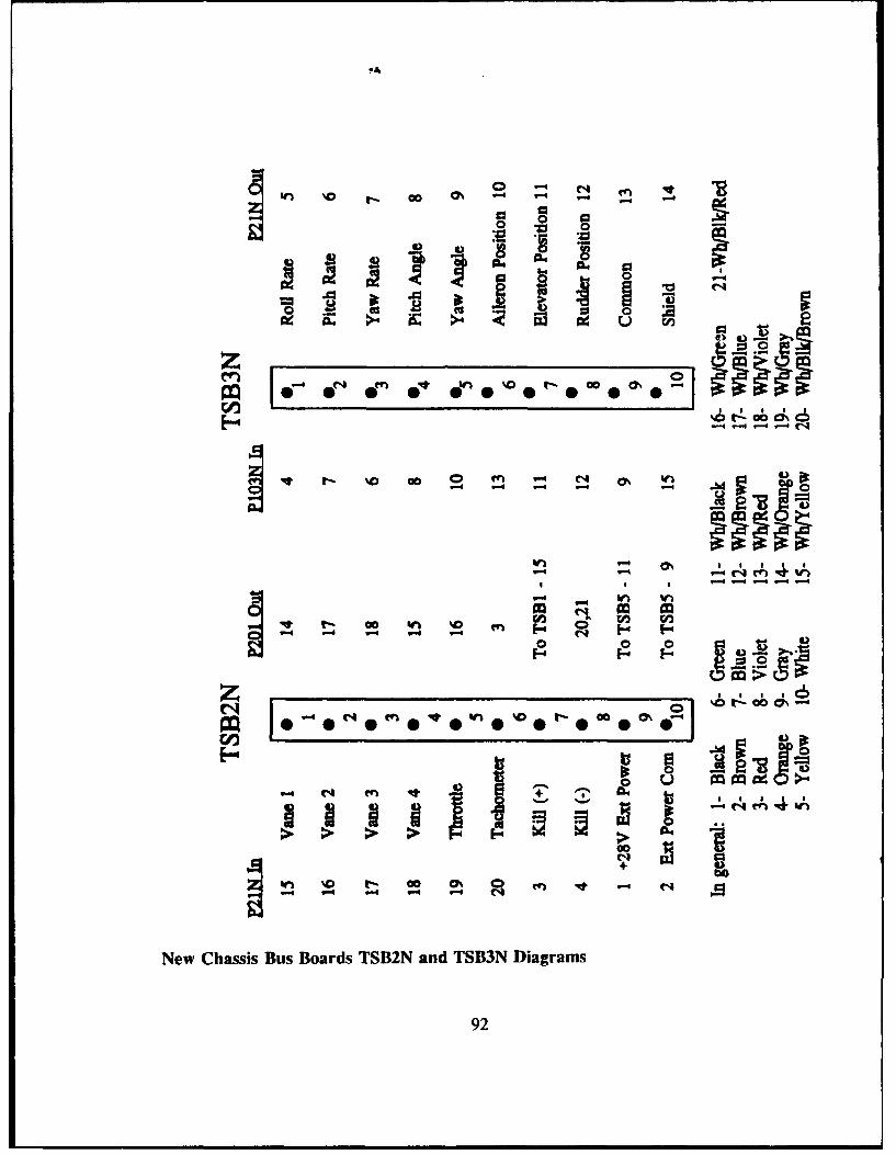
00
mr ~0 0%~
V. 0- %00n 4M i
2 2
W). -)
0 0 in %0 * 0
~~~ t.- c6 @0 %
-44 -4 A
H 00
00 M
(' V 4 -
New Chassis Bus Boards TSB2N and TSB3N Diagrams
92

II T_.. .... ... . . ... .. - U.... . & I D UWfAVAVA*4 0---
Futaba.FP -.S 34 For J. M, SG. MAGNUM. and CHALLENGER Series
FPS4For E. F. G. R L. IieLarge high torque watprtight and dustpronf servos
* r 'iI I ..... , ~ ,.. . ..l.Ii It a ,* . .... ,.~ . , ,.i . .
'I. I I4 ~ ~ ~ ~ ~ ~ ~ I f.' I A" I' I'' t. . lI I., ll" I I, ,, lh I I A 1 1.PrI 9I -'I
SO .1..1...... .......
I,.i.,I,,,,,.i, ,,t,0-,,I I. I .. *..,,lI..,
,,^ , ,I .I..I
I , . 'I ,,2 3*,+,,~ls•,€ III" Vl• ~ ll.'
IV +phI 2 + ' ,L. Ni + I+
I I " . I A V ' I r f I
II$!hN A IWPN 1h . h ORN (7 ,lr . Il .).. i I)l )F m V,' VV', F.
Futaba FP-834 Quarter-scale Servo Specifications
93

Iv1S-74-,VVB
LI _
rj
-__---_-' _, ------74 7W
--
7= 7 rr,- i frr h _
IS
SPECIFICATIONS
SIZE: 2 x3-2' x1 -:, (54.OxSO.0x2S.3mm]WEIGHT: 3.9OZ(110:3SPEED: 0.26 SECISO DEGREESTOROUE: 167 OZIIN (12 (GICMlJIN'UT VOLTAGE: 4.8-6.0 V DCINPUT SIGNAL: CONVENTIONAL RIC POSITIVE PULSE
WIDTH MODULATION WITH 1 .SMS 0.5US NEUTRAL
CURRENT NSUMPTION: IDLE .......... 25MANO LOAD....300MAMAX. ..... 140OLIA
OUTPUT ROTATION: SO & 160 DEGREES. TWO TYPESFEATUPES:MS-747WB SERVO HASlA HEAVY DUTY
OUTPUT SHAFT WITH BALL BEARING AND0-RING SEAL RUGGED EXTRA-THICKGEARS. ARM AND DISK. EXCELLENTMECHANICAL AND ELECTRONICS QUALITY.
Condor RC MS-747WB Servo Specifications
94

APPEND)IX C: AROD SCHEMIATICS- AROI)-3 FORrEBODY & SHEET 2 OF 2
LIM
A L '- I -
AR D3Frbd ce ai cShe I of 2f____________
951

iL ~ -- hi
II
T i -. Iv
I;'.
. = -,, ,:-- -, i-
AROD-3 Forebody Schematic, Sheet 2 of 2
96
- ____

0 +r
, '<
-0 0-
2u
UUE U'
- .- 0nd
-- .• . ... ..
I > + als iBL
<I<
.- m+, UC ..Arphyta F0o 0
Doi D2O
M PVt d
a<2u Um
L~hL
L3L
aiV... ..M IA/<
ArchtasForehody Schematic, Sheet 1 of 2
97
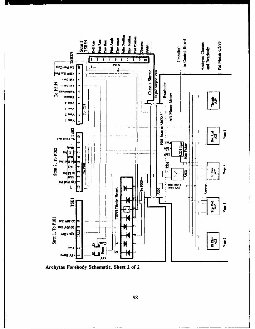
e'4n
ILL
rg ARE#
-as I - -- ----- --- -- I >
!i ll __ -- U_oq j. ... 0 j) -
zl
SAnoiq=L %D C4i7Pc y s Fore d O
980
~~Pu9 AU. :
PI AL
F
jIJ 2 U A * U1UA5
Arhya FrboyScemtcSee ,o
1OdIN d~I' '98

APPENDIX D: ARCHYTAS UAV ENGINE RUN CHECKLIST
ARCHYTAS ENGINE RUN CHECKLIST 1/22/93 PJM
SetupKeys for Bldg 249Vehicle/stand to Bldg 249 (at least 2 people if pushing, or pull w/truck)Computer setupOscilliscope wiprobes & cordVoltneter wiprobes (runs on battery if desired)External power supply 28 VDCTools- allen wrenches, screw drivers, etcGasoline- premixed w/oilFuel pump (pressurize gas can to feed fuel)Extension cords (I already at Bldg 249, bring 1)Video camera w/filmEar protection: Foamies/MickeyMouse earsSafety glassesElectrical tapePaper towelsSoldering Gun & solderOther items:
EnQine RunsNotify Prof Howard (X2870) of run/times (phone in Bldg 230- Don has ke',)Run area swept cleanEngine stand jacks raisedPersonnel rqrd: computer operator (kill switch during start)
brakeman (set brake with tie wrap if no roll rqrd)starter (assume kill switch duty when engine started)
All duties clearly-defined, primary operator designatedHand signals understood by all (due to noise)Hearing & eye protect-onComputer up & runningGeneral vehicle security walkaround- no loose panels, wires, etc.Fire extinguisher nearby (hanging outside entrance to Bldg 249)Golf course clearCamera runningExtra observers well forward of vehicle
DutiesComputer operator- throttle, joystick, kill switch (primary operator)Brakeman- stand by brake, (may be omitted if no roll rqrd)Starter- pull start cord, (man kill switch once engine started)Camera operator- safety obsrvr, stand by fire ext (omit w/camera on auto)MINIMUM PERSONNEL: 2 (camera running, no roll rqrd)
Reminder: KEYS FOR BLDG 249
99

LIST OF REFERENCES
1. Kaminer, I. I., "Avionics Systems Design AE 4276 Class Notes," NavalPostgraduate School, Monterey, CA, March, 1993.
2. Merz, P. V., Development and Testing of the Digital Control System for theArchytas Unmanned Air Vehicle, Master's Thesis, Naval Postgraduate School,Monterey, CA, December, 1992.
3. Davis, J. P., Design of a Robust Autopilot for the Archytas Prototype using LinearQuadratic Synthesis, Master's Thesis, Naval Postgraduate School, Monterey, CA,December, 1992.
4. Munson, K., World Unmanned Aircraft, Jane's Publishing Co., 1988.
5. Department of Defense, Unmanned Aerial Vehicles (UA V) Master Plan 1992,pp. 34-6, 15 April 1992.
6. Draft Proposal, "Development of a Robust Autopilot/Autoland System for theClose-Range Unmanned Air Vehicle", by R. M. Howard and I. I. Kaxniner, NavalPostgraduate School, Monterey, CA, 1992.
7. Brynestad, M.A., Investigation of the Flight Control Requirements of a Half-scaleDucted Fan Unmanned Air Vehicle, Master's Thesis, Naval Postgraduate School,Monterey, CA, 1992.
8. AROD Development Status, System Description and Technical Considerations,Sandia National Laboratory, December, 1986.
9. Stoney, R. B., Design and Fabrication of a Vertical Attitude Takeoff and LandingUnmanned Air Vehicle, Master's Thesis, Naval Postgraduate School, Monterey,CA, June, 1992.
10. Humphrey Inc. Product Summary Catalog, June 1992.
11. MAST Project, Technical Report #1, by A. P. Pascoal, IST, Lisbon, Portugal,COWlconsult, Copenhagen, Denmark, and ORCA Instrumentation, Brest, France,March, 1992.
100
12. Kuechenmeister, D. R. A High-fidelity Non-linear Simulation of an AutonomousUnmanned Air Vehicle, Master's Thesis, Naval Postgraduate School, Monterey,CA, June, 1993.
13. Webster's Ninth New Collegiate Dictionary, p. 1076, Merriam-Webster Inc., 1986.
14. Kaltenberger, B. R., Design of a Robust Autopilot for the Archytas Prototype inHover Mode via LQR Synthesis, Master's Thesis in progress, Naval PostgraduateSchool, Monterey, CA, to be pubhshed September, 1993.
15. Phone Conversation with Mr. C. Cross, Futaba RC Inc., Irvine, CA, April, 1993.
16. Brand, D., "Understanding PCM for Model Radio Control," Heliscene Magazine,Issue 3, pp. 60-64, Early Summer, 1991.
17. Hoffman, A., Letter to Archytas Project Working Group, dated 2 March 1993.
18. Kelly, A., and Pohl, I., A Book on C.- Programming in 'C', Second Edition,Benjamin/Cummings, 1990.
19. Franklin, G.F., Powell, J.D., and Emami-Naeini, A., Feedback Control ofDynamic Systems, Second Edition, Addison-Wesley, April, 1991.
101

INIIAL DISTREBUTrION LIST
No. Copies1. Defense Technical Information Center 2
Cameron StationAlex.•.dria VA 22304-6145
2. Library, Code 052 2Naval Postgraduate SchoolMonterey CA 93943-5002
3. Chairman, Code AADepartment of Aeronautics and AstronauticsNaval Postgraduate SchoolMonterey, CA 93943-5100
4. LCDR Patrick J. MoranCommandant (G-EAE-3)U.S. Coast Guard Headquarters2100 2nd St. SW.Washington, DC 20150
5. Professor Richard M. Howard, Code AA/Ho 2Department of Aeronautics and AstronauticsNaval Postgraduate SchoolMonterey, CA 93943-5100
6. LCDR Michael K. Shields, Code EC/Sh 2Department of Electrical and Computer EngineeringNaval Postgraduate SchoolMonterey, CA 93943-5100
7. Professor Isaac I. Kaminer, Code AA/KaDepartment of Aeronautics and AstronauticsNaval Postgraduate SchoolMonterey, CA 93943-5100
102

8. Mr. Don MeeksUAV Lab, Building 214Naval Postgraduate SchoolMonterey, CA 93943-5100
9. CDR B. J. NiesenCommandant (G-aOLE)U.S. Coast Guard Headquarters2100 2nd St. SW.Washington, DC 20150
10. CDR R. RenoudCommandant (G-EAE-4)U.S. Coast Guard Headquarters2100 2nd St. SW.Washington, DC 20150
11. LT Paul Merz2709 State St.Gautier, MS 39553
103