seismicrehabilitationperformanceofsteelsideplate ... · pdf filethe weld electrode was e70t-7...
TRANSCRIPT

EARTHQUAKE ENGINEERING AND STRUCTURAL DYNAMICSEarthquake Engng Struct. Dyn. 2010; 39:23–44Published online 17 June 2009 in Wiley InterScience (www.interscience.wiley.com). DOI: 10.1002/eqe.931
Seismic rehabilitation performance of steel side platemoment connections
Chung-Che Chou1,2,∗,†,‡,§ , Keh-Chyuan Tsai1,2,¶ ,‖, Yuang-Yu Wang3
and Chih-Kai Jao4,∗∗
1Department of Civil Engineering, National Taiwan University, Taipei, Taiwan2National Center for Research on Earthquake Engineering, Taipei, Taiwan
3College of Civil Engineering, Tongji University, Shanghai, China4Department of Civil Engineering, National Chiao Tung University, Hsinchu, Taiwan
SUMMARY
Moment connections in an existing steel building located in Kaohsiung, Taiwan were rehabilitated to satisfyseismic requirements based on the 2005 AISC seismic provisions. Construction of the building was ceasedin 1996 due to financial difficulties and was recommenced in 2007 with enhanced connection performance.Steel moment connections in the existing building were constructed by groove welding the beam flangesand bolting the beam web to the column. Four moment connections, two from the existing steel building,were cyclically tested. A non-rehabilitated moment connection with bolted web-welded flanges was testedas a benchmark. Three moment connections rehabilitated by welding full-depth side plates between thecolumn face and beam flange inner side were tested to validate the rehabilitation performance. Test resultsrevealed that (1) the non-rehabilitated existing moment connection made by in situ welding process priorto 1996 had similar deformation capacity as contemporary connection specimens made by laboratorywelding process, (2) all rehabilitated moment connections exhibited excellent performance, exceedinga 4% drift without fractures of beam flange groove-welded joints, and (3) presence of the full-depthside plates effectively reduced beam flange tensile strain near the column face by almost half comparedwith the non-rehabilitated moment connection. The connection specimens were also modeled using thenon-linear finite element computer program ABAQUS to further confirm the effectiveness of the side platein transferring beam moments to the column and to investigate potential sources of connection failure.A design procedure was made based on experimental and analytical studies. Copyright q 2009 JohnWiley & Sons, Ltd.
Received 20 June 2008; Revised 22 April 2009; Accepted 24 April 2009
KEY WORDS: rehabilitated steel moment connection; side plate; cyclic test; finite element analysis
∗Correspondence to: Chung-Che Chou, Department of Civil Engineering, National Taiwan University, Taipei, Taiwan.†E-mail: [email protected]‡Associate Professor.§Associate Research Fellow.¶Professor of Civil Engineering.‖Director.∗∗Former Graduate Student.
Copyright q 2009 John Wiley & Sons, Ltd.

24 C.-C. CHOU ET AL.
INTRODUCTION
A building utilizing traditional bolted web-welded flange moment connections can experience weldfracture during moderate or severe earthquakes, leading to insufficient ductility. Many traditionalsteel moment connections, which were fabricated following pre-Northridge construction practiceswith low notch toughness E70T-4 electrode, showminimal plastic deformation (e.g. 1% drift) beforeweld fracture at the beam-to-column interface [1–3]. The essence of all rehabilitated connectionschanges the relative strength ratio of a welding connection and the beam section near the columnface to make beam yielding prior to fractures of a welding connection, consequently improvingthe ductility of an entire connection. Weakening schemes include the use of a reduced beamsection or reduced flange plates near the beam-to-column interface to avoid groove weld fractureor beam buckling [4–6]. Strengthening schemes include the use of cover plates, upstanding ribs,and haunches near the beam-to-column interface [7–12]. The beam flanges near the column facecan be rehabilitated to remain elastic, preventing groove weld fracture.
The ER70S-6 electrode, similar to the E71T-8 or E70TG-K2 electrodes, provides a minimumspecified Charpy V-Notch value of 27 J at −29◦C (20 ft-lbs at −20◦F), which is accepted by AISC[13] for beam flange groove welds. Since the ER70S-6 electrode is used to conduct the beamflange groove welds to the box column in Taiwanese construction practices, the connection showsa better performance (e.g. 3% drift) than pre-Northridge moment connections utilizing the E70T-4electrode. However, these connections still fail to satisfy connection performance requirements,specified based on AISC [13] and FEMA 350 [14]. When a composite slab is present in theexisting building, introducing a reduced beam section, reduced flange plates, upstanding ribs, orcover plates near the beam-to-column interface cause slab damages. Although the welded haunchscheme eliminates the need to modify the existing top flange welds, reducing a clear heightnear the beam-to-column interface might cause discomfort to occupants. This study [15] thusprovides a rehabilitation scheme for improving the cyclic performance of steel moment connections,minimizing interference from the composite slab, and reducing story height requirements in anexisting steel building in Taiwan.
Construction of a 34-story steel hotel in Kaohsiung, Taiwan started in 1993 and the erectionof the entire frame and the pouring of concrete slabs up to the 26th floor were completed before1996. Owing to the financial difficulties faced by the developer, the construction of the originalhotel was suspended for 10 years. Recently, this building has been rehabilitated for residentialpurposes. Since the original structural system could not meet new seismic requirements mandatedin 2005, several retrofitting schemes were adopted in the reconstruction project to upgrade theseismic performance of the existing building. In some bays, buckling-restrained braces were addedfrom the 1st to 11th floors, and eccentrically braced links were added from the 12th to 25thfloors. All the existing moment connections, which were made based on the pre-Northridge-typedetails but with the high toughness electrode, were rehabilitated by adding a pair of full-depthside plates near the column face and inside the beam flanges without removing the concreteslab. A research [16] investigating the seismic demands for the existing and retrofitted buildingssubjected to design-based and maximum-considered earthquakes confirmed the effectiveness ofthose retrofitting structural elements. The inelastic time-history analyses suggested that peak inter-story drifts of the original and the retrofitted structures reached about 1.2% and 1.4%, respectively,under maximum-considered earthquakes. The rotational demand imposed on the welded momentconnection was about 1–1.5% for both the existing and retrofitted structures, smaller than therotational capacity (2–3% drift) found in the tests of moment connection specimens prior to
Copyright q 2009 John Wiley & Sons, Ltd. Earthquake Engng Struct. Dyn. 2010; 39:23–44DOI: 10.1002/eqe

REHABILITATION PERFORMANCE OF STEEL SIDE PLATE MOMENT 25
1996 [17]. In their study [17], connection specimens used ASTM A36 steel beams with sectionsranging from H530×160×10×14 (W21×50) to H545×315×13×20 (W21×101), smaller thanthose in the existing building. All flange groove welds were made in the laboratory with thespecimen in an upright position to simulate field conditions. The weld electrode was E70T-7made by Lincoln electric company and provided no specified level of toughness. Therefore, theperformance of the existing moment connection was expected to exceed seismic demands accordingto inelastic time-history analyses of the building, but violate requirements based on the 2005 AISCseismic provisions [13]. The owner and the design engineer of the building made the performanceset for rehabilitated moment connections to meet strength and ductility requirements (4% drift)prescribed in AISC seismic provisions [13].
Cyclic testing was performed on four exterior moment connections, two of which were removedfrom the existing steel building. A rehabilitation scheme was proposed to strengthen three connec-tions by adding a pair of full-depth side plates between the column face and beam flange innerside. The side plates are intended to help transfer some beam moments to the column becausethe existing beam flange groove-welded joints could sustain modest inelastic deformation beforefracturing [11, 17, 18]. No need is required to modify the existing groove welds of the beam topand bottom flanges, indicating no damages in an existing composite slab. This scheme differs fromthat utilizing the side plate connection [14], which completely eliminates the reliance on existingbeam flange groove-welded joints at the column face for transferring beam moments.
In this paper, weld and fabrication details, which represent the existing connection specimens,are presented first. Test results show that the actual performance of the existing moment connec-tions before and after rehabilitation is then presented to validate the rehabilitation scheme. Theeffects of in situ welding and laboratory welding processes on connection performance are alsostudied. Finally, the connection specimens are modeled using the non-linear finite element computerprogram ABAQUS [19] to confirm the effectiveness of the side plate in transferring beam momentsto the column and to investigate potential sources of connection failure. A step-by-step designprocedure is presented based on the test and analytical results.
REHABILITATED MOMENT CONNECTION
Figure 1 shows a rehabilitated moment connection using a pair of side plates between the columnface and the beam flange inner side. These two plates are used to transfer some beam flangeforce to the column to reduce beam flange strain and prevent groove weld fracture. The figureshows moment demand, Mdem, along the beam, assuming that a plastic hinge is located at aquarter beam depth from the end of the side plates. This location is used based on the FEMA350 [14] recommendation for connections reinforced with either cover plates or welded haunches.The moment at the column face, as determined by projecting moment capacity MPH at the plastichinge location, is
Mdem= Lb
Lb−(Ls+db/4)MPH= Lb
Lb−(Ls+db/4)(�Ry�ynZb) (1)
where Lb is the distance from the mid-span to the column face, Ls is the side plate length, db isthe beam depth, Zb is the plastic section modulus of the beam, �yn is the specified yield strengthof the steel, Ry is the material over-strength coefficient, and coefficient � denotes strain hardening[14]. Since steel properties were obtained from tensile coupon tests before fabricating rehabilitated
Copyright q 2009 John Wiley & Sons, Ltd. Earthquake Engng Struct. Dyn. 2010; 39:23–44DOI: 10.1002/eqe

26 C.-C. CHOU ET AL.
Figure 1. Moment capacity and demand along a beam axis.
specimens, actual yield strength, tensile strength, and Ry=1 were used in Equation (1) to estimatethe moment demand, Mdem.
Moment capacity, Mcap, near the beam-to-column interface increases as a result of the sideplates. Although the stress distributions near the beam-to-column interface are complicated, asimple bending theory is adopted to estimate the flexural capacity of the rehabilitated beam, whichis the summation of the flexural strengths of the beam, Mpb, and the two side plates, Mps
Mcap=Mpb+Mps= ZbRy�yn+ 12 (db−2tf)
2Ry�ynts (2)
where tf is the beam flange thickness and ts is the side plate thickness. It is assumed that the sideplates are subjected to the top and bottom flange force, PsF, as shown in Figure 2(b), and exhibita fully plastic stress state (Figure 2(c)). By considering moment equilibrium in the side plate, theforce, PsF, is:
PsF= Fs[ 12 (db−2tf)]db−2tf
= 14 (db−2tf)Ry�ynts (3)
Copyright q 2009 John Wiley & Sons, Ltd. Earthquake Engng Struct. Dyn. 2010; 39:23–44DOI: 10.1002/eqe

REHABILITATION PERFORMANCE OF STEEL SIDE PLATE MOMENT 27
Figure 2. Side plate flexural stress state: (a) elevation; (b) side plate; and (c) stress distribution.
Additionally, the force PsF is transferred to the side plate through shear on the groove-welded jointbetween the side plate and beam flange inner side, and thus the minimum length of the side plate,Ls, is determined based on groove weld strength
Ls�14 (db−2t f)Ry�yn0.8(0.6Fexx )
(4)
where Fexx is the weld strength. Assuming that the rehabilitated beam moment capacity–demandratio, �(=Mcap/Mdem), is larger than one, the side plate thickness, ts, can be calculated usingEquation (2):
ts��Mdem−Mpb
12 (db−2tf)2Ry�yn
(5)
Copyright q 2009 John Wiley & Sons, Ltd. Earthquake Engng Struct. Dyn. 2010; 39:23–44DOI: 10.1002/eqe

28 C.-C. CHOU ET AL.
When these two side plates are added to the beam-to-column interface, the strong column–weakbeam criterion should also be checked
�=∑
Zc(�yn−�a)∑Mc
>1 (6)
where Zc is the plastic section modulus of the column above and below the connection, �a is theaxial stress in the column above and below, and Mc is the sum of the column moments resultingfrom the development of the probable beam plastic moment MPH within each beam that framesinto the connection. It can be computed using
∑Mc=n
[MPH
Lb+dc/2
Lb−(Ls+db/4)+Vg
(dc2
+Ls+ db4
)]Hc−dbHc
(7)
where Hc is the column length measured from top and bottom inflection points, dc is the columndepth, Vg is the beam shear at the plastic hinge location produced by gravity load in beam span,and n is equal to 1 and 2 for the exterior and interior moment connections, respectively.
TEST PROGRAM
Connection specimens
The experimental program consisted of tests of four specimens, each of which represented anexterior moment connection with one steel beam and one welded box column. Table I lists thebeam, column, and side plate sizes. The column width is 2.2–2.8 times the beam width, andthe column thickness is 1.25–1.67 times the beam flange thickness. The column has continuityplates as thick as the beam flange. ASTM Grade 50 steel was utilized for the column, continuityplate, and side plate; ASTM A36 steel was utilized for the beam. The specimens UR and SP1were removed from the 33rd floor of an existing steel building located in Kaohsiung, Taiwan,whereas Specimens SP2 and SP3 were fabricated in the laboratory. Specimen UR represented anunreinforced bolted web-welded flange fully restrained moment connection (Figure 3(a)) and wastested as a benchmark.
Specimen SP2 (Figure 3(b)) was identical to Specimen SP3, except that (1) the side plate sizewas 22×300mm in the Specimen SP2 and 18×254mm in the Specimen SP3, and (2) SpecimenSP3 had side plate length, Ls, less than the required value of 264mm based on Equation (4). Theobjective was to discover the possible failure mode in the rehabilitated connection. Table II listsinformation for beam moment capacity, demand, and values of �, �, and �. The rehabilitated beammoment capacity–demand ratio, �(=Mcap/Mdem), is varied to study the effects of reinforcement onconnection cyclic behavior and to discover the minimum reinforcement for the proposed connection.The strong column–weak beam ratio, �, according to Equation (6) is high because only one beamplastic moment and no axial stresses in the column are considered to represent the test specimencondition.
Welding and fabrication details for existing and laboratory moment connections
All the real and lab specimens were welded by the self-shielded flux-cored arc welding process usingthe ER70S-6 electrode. This electrode, which is similar to the E71T-8 or E70TG-K2 electrodes,
Copyright q 2009 John Wiley & Sons, Ltd. Earthquake Engng Struct. Dyn. 2010; 39:23–44DOI: 10.1002/eqe

REHABILITATION PERFORMANCE OF STEEL SIDE PLATE MOMENT 29
TableI.Mem
bersizesandproperties.
Colum
nstreng
thBeam
flang
estreng
thBeam
web
streng
thSide
platestreng
thColum
nsize
/beam
Side
platesize
Spe
size
�∗ y(M
Pa)
�† u(M
Pa)
� y(M
Pa)
� u(M
Pa)
� y(M
Pa)
� u(M
Pa)
(ts×
Ls)
� y(M
Pa)
� u(M
Pa)
UR
700×7
00×3
5×3
539
152
527
548
528
849
5—
——
H70
2×2
54×1
6×2
8
SP1
700×7
00×3
5×3
539
152
525
041
838
543
720
×300
400
557
H68
8×2
55×1
3×2
1
SP2
550×5
50×3
5×3
538
553
025
041
828
043
722
×300
370
500
H70
2×2
54×1
6×2
8
SP3
550×5
50×3
5×3
538
553
025
141
328
143
418
×254
400
532
H70
2×2
54×1
6×2
8
∗ Actualyieldstreng
th.
† Actualtensile
streng
th.
Copyright q 2009 John Wiley & Sons, Ltd. Earthquake Engng Struct. Dyn. 2010; 39:23–44DOI: 10.1002/eqe

30 C.-C. CHOU ET AL.
Figure 3. Connection details: (a) Specimen UR and (b) Specimen SP2.
Table II. Beam moment capacity–demand ratio after rehabilitation.
Specimen � Mpb (kNm) MPH (kNm) Mdem (kNm) Mps (kNm) Mcap (kNm) � �
SP1 1.34 1273 1705 1969 1669 2942 1.49 7.5SP2 1.34 1666 2232 2572 1699 3364 1.31 3.5SP3 1.32 1672 2207 2506 1502 3175 1.27 3.6
provides a minimum specified Charpy V-Notch value of 27 J at −29◦C (20 ft-lbs at −20◦F). RealSpecimens UR and SP1, removed from the 33rd floor of the existing building, were constructedbased on the typical construction practice in Taiwan prior to 1996. First, the steel beam waspositioned to the column shear tab and the web bolts were installed and fully tensioned. Thebacking bar projected 50mm beyond the both sides of the beam flange and weld tabs was attachednext to the beam flange. The beam flanges were then groove welded to the column flange. Eachpass of flange groove welds was initiated, and terminated when possible, at a point outside theflange. This was done to prevent poor-quality welds, which normally occur at the initiation of theweld at the beam flange-to-column face. Finally, supplemental welds between the shear tab andthe beam web were conducted. For Specimen SP1, complete-penetration single-bevel groove weldswere used to connect the side plate to the beam and column flanges. Each pass of side plate tobeam flange groove welds was initiated at a point outside the side plate and terminated at a pointat the column flange. Each pass of side plate to the column flange groove welds was then initiatedfrom the beam bottom flange and terminated at the beam top flange. All backing bars used for thegroove welds were left in place after welding was complete. Ultrasonic tests (UT) were conductedfor all flange groove welds, and they all satisfied the prescribed acceptance criteria [20].
Copyright q 2009 John Wiley & Sons, Ltd. Earthquake Engng Struct. Dyn. 2010; 39:23–44DOI: 10.1002/eqe

REHABILITATION PERFORMANCE OF STEEL SIDE PLATE MOMENT 31
Figure 4. Test setup.
Lab welds for Specimens SP2 and SP3 were made by a fabrication shop welder, using weldpositions typical to shop welding. More specifically, beam flange to column groove welds weremade with the specimen oriented to permit flat position welding. Because the column was placedhorizontally, each pass of side plate to column flange groove welds was conducted before eachpass of side plate to beam flange groove welds. Each pass of side plate to beam flange groovewelds was initiated at a point at the column face and terminated at a point outside the sideplate. Supplemental fillet welds between the shear plate and the beam web were not adopted,and weld tabs were also not used for the beam flange groove welds. The backing bars, whichwere about 60mm wider than the beam flange width, remained in place after the welding wascomplete. For all specimens, a fillet weld, helping to reduce the notch effect of a left in placebacking bar from a theoretical perspective, was not made between the backing bar and thecolumn.
Test setup and loading protocol
The exterior connection specimens were tested as shown in Figure 4. Restraint to lateral-torsionalbuckling of the beam was provided near the actuator and at a distance of 1000mm from the columnface. Displacements were imposed on the beam by a 1000 kN actuator at a distance of 3875mmfrom the column centerline. The AISC cyclic displacement history [13] was used and run underdisplacement control. The inter-story drift, which was computed by the actuator displacementdivided by the distance to the column centerline, was used as the control variable. Specimens weretested until connection failure occurred or limitations of the test setup were reached.
Copyright q 2009 John Wiley & Sons, Ltd. Earthquake Engng Struct. Dyn. 2010; 39:23–44DOI: 10.1002/eqe

32 C.-C. CHOU ET AL.
TEST RESULTS
Non-rehabilitated existing moment connection
Figure 5(a) shows the global response of Specimen UR; the moment computed at the columnface is normalized by the nominal plastic moment of the beam, Mnp. Minor whitewash flaking,indicating beam yield, was observed in the beam flange near the groove weld at an inter-storydrift of 0.75%. At an inter-story drift of 1.5%, significant yielding was observed along the weldboundary of the beam top portion, which included points at the edge of the beam flange adjacentto the groove weld, the edge of the shear plate adjacent to the fillet weld on the column flange, andthe toe of the weld access hole. Minor fractures were initiated at these three points at an inter-storydrift of 3%, but no fracture was observed in the beam bottom portion. Deterioration in the overallstrength of the specimen was not observed until the fractures propagated across almost the fullflange width (Figure 6(a)) and 140mm long along the shear plate edge (Figure 6(b)) at a −4%drift. Note that these fractures initiating adjacent to the edge of the in situ weld extended in a stablemanner in the base metal (heat-affected zone). A crack initiating at the toe of the weld access holedid not propagate. This beam flange failure mode was similar to that observed in prior tests ofconnection specimens [17]; all the flange welds in these specimens were made in the laboratoryby a certified shop welder in simulating in situ welding conditions. After top flange fracture, thespecimen was reversely loaded to an inter-story drift of 4% so that the beam bottom flange was intension. A minor crack was initiated at the toe of the weld access hole, but no crack was initiated atthe heat-affected zone of the beam bottom flange or the shear plate. No visible sign of yielding inthe column panel was observed during the test. Based on observed performance in Specimen UR,it is judged that this specimen made by in situ welding process prior to 1996 and accepted by theUT examination has similar deformation capacity as contemporary connection specimens madeby the lab welding process [17]. It suggests that the use of high toughness electrodes is highlybeneficial. Even if a reduction of toughness is suffered due to improper welding conditions (fieldversus laboratory), a substantially high level of toughness can still remain, leading to moderatedeformation capacity of the beam. Although the existing connection specimen before rehabilitationshows good performance, exceeding seismic demands (1–1.5% drift) obtained from inelastic timehistory analyses of the steel frame [16], it fails to satisfy a current ductility requirement (4% drift)prescribed in AISC seismic provisions [13]. It also indicates that the drift requirement per AISCseismic provisions [13] is seemingly too stringent and may be investigated for a proper limit.
Rehabilitated moment connection
Figure 5(b) shows the hysteretic responses of Specimen SP1, which achieved high inter-story driftwithout welded joint fracture. Specimen SP1 was removed from the existing steel building andretrofitted with two side plates in the field. Unlike Specimen UR, the beam flange near the grooveweld showed no sign of yielding during initial loading. Instead, the beam flange near the endof the side plate yielded at an interstory drift of 0.75–1%. Beam flange yielding expanded withincreasing drift and the beam flange adjacent to the column groove weld showed sign of yieldingat an inter-story drift of 2%. Crack initiation as observed in Specimen UR test was not detected inSpecimen SP1 test at an inter-story drift of 3%, where beam flange and web local buckling outsidethe side plate commenced. Local buckling was accompanied by a twisting of the beam outsidethe side plate, and resulted in a gradual reduction in the specimen capacity at an inter-story driftof 4%. Finally, the flange local buckling initiated tearing of the beam flange immediately adjacent
Copyright q 2009 John Wiley & Sons, Ltd. Earthquake Engng Struct. Dyn. 2010; 39:23–44DOI: 10.1002/eqe

REHABILITATION PERFORMANCE OF STEEL SIDE PLATE MOMENT 33
Figure 5. Beam moment-deflection responses: (a) UR; (b) SP1; (c) SP2; and (d) SP3.
Figure 6. Specimen UR failure modes (−4% drift): (a) beam top flangefracture and (b) shear plate fracture.
to the edge of the side plate groove weld. After the beam finished two cycles of a 4.7% drift,testing was stopped due to limitations in the test setup. Fractures as observed in non-rehabilitatedSpecimen UR were not found in this specimen at the end of testing (Figure 7), indicating that twoside plates near the column face can improve seismic performance of the actual connection madeby in situ welding process prior to 1996.
Copyright q 2009 John Wiley & Sons, Ltd. Earthquake Engng Struct. Dyn. 2010; 39:23–44DOI: 10.1002/eqe

34 C.-C. CHOU ET AL.
Figure 7. Specimen SP1 beam buckling (4.7% drift).
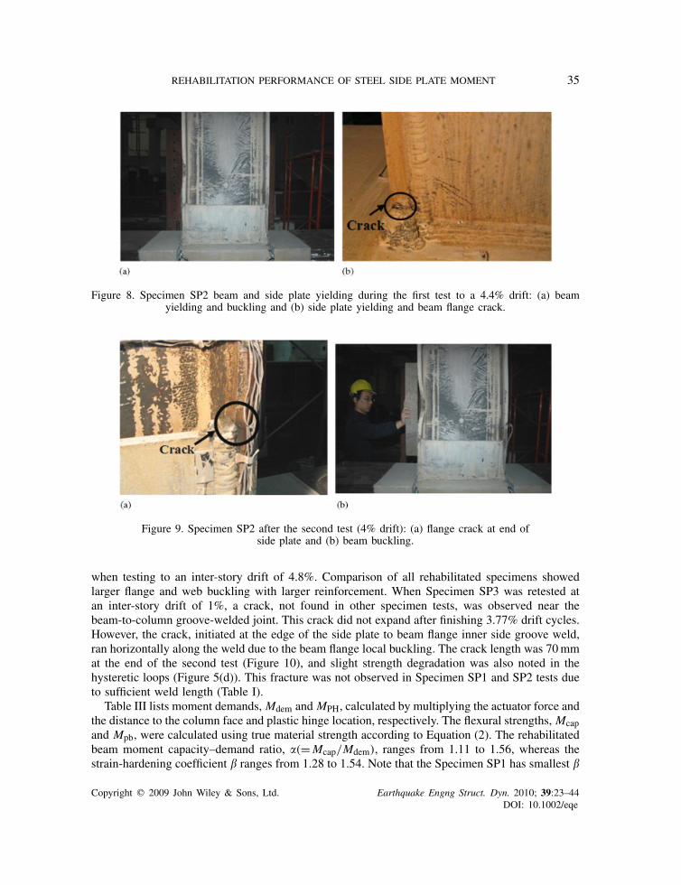
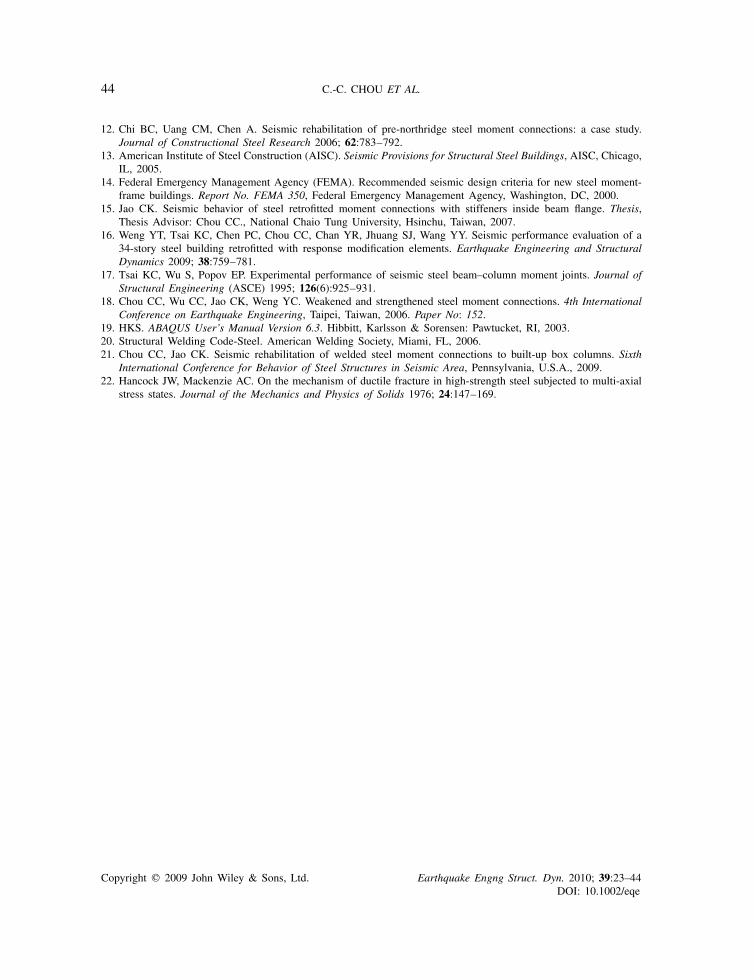
Beam flange to column groove welds in Specimens SP1 and SP2 were made in the existingbuilding prior to 1996 and laboratory in 2007, respectively. Moreover, the rehabilitated beammoment capacity–demand ratio, �, was lower in Specimen SP2 than Specimen SP1. The beamflange of Specimen SP2 near the groove weld and the end of the side plate yielded at an inter-storydrift of 0.75–1%. The side plate near the junction of the beam flange and column showed yieldingat an inter-story drift of 3%. Figure 8(a) shows the beam deformation of Specimen SP2 during thefirst test to an inter-story drift of 4.4%; flange and web buckling amplitudes were about 14mm and16mm, respectively, much smaller than those observed in Specimen SP1 test. A crack, as noted inSpecimen UR, was also observed at edges of the beam top and bottom flanges adjacent to the groovewelds (Figure 8(b)), but deterioration in the overall strength of the specimen was not observed atthe end of test. This crack was not observed in Specimen SP1 with large reinforcement, suggestingthat the moment capacity–demand ratio (or side plate size) may have played an important rolein reducing stress concentration. It is unclear how severe this stress concentration is and underwhat circumstances it may become a significant factor in rehabilitated connection performance.Therefore, Specimen SP2 was retested instead of loading to a larger drift due to limitations in thetest setup. When Specimen SP2 was retested to an inter-story drift of 1%, flange cracks near theend of the side plates, as noted in Specimen SP1 test at a 4.7% drift, were observed. This cracklength increased to 10mm (Figure 9(a)) after finishing two cycles of a 4% drift; significant beambuckling was also noted (Figure 9(b)), leading to slight strength degradation (Figure 5(c)). Thecracks as noted at edges of the beam flanges adjacent to the groove welds during the first test(Figure 8(b)) did not expand and affect the connection cyclic performance during the second test.No weld fracture and no column panel zone yielding were observed after the second test. Havingobserved cyclic performance in rehabilitated Specimens SP1 and SP2 further confirms that as longas the high toughness electrode is used with side plate reinforcement, specimens made either inthe field or laboratory exceed a drift requirement of 4% per AISC seismic provisions [13]. Notethat Specimen UR made by using the high toughness electrode alone cannot ensure the satisfactionof the concerned drift requirement of 4%.
Specimen SP3 was identical to Specimen SP2 except that Specimen SP3 had a small side plateand an insufficient side plate length (Table I). No beam buckling was observed after the specimenfinished 4% drift cycles. However, a minor crack was observed at the edge of the groove weldbetween the beam flange inner side and the side plate. Beam buckling was difficult to detect even
Copyright q 2009 John Wiley & Sons, Ltd. Earthquake Engng Struct. Dyn. 2010; 39:23–44DOI: 10.1002/eqe
REHABILITATION PERFORMANCE OF STEEL SIDE PLATE MOMENT 35
Figure 8. Specimen SP2 beam and side plate yielding during the first test to a 4.4% drift: (a) beamyielding and buckling and (b) side plate yielding and beam flange crack.
Figure 9. Specimen SP2 after the second test (4% drift): (a) flange crack at end ofside plate and (b) beam buckling.
when testing to an inter-story drift of 4.8%. Comparison of all rehabilitated specimens showedlarger flange and web buckling with larger reinforcement. When Specimen SP3 was retested atan inter-story drift of 1%, a crack, not found in other specimen tests, was observed near thebeam-to-column groove-welded joint. This crack did not expand after finishing 3.77% drift cycles.However, the crack, initiated at the edge of the side plate to beam flange inner side groove weld,ran horizontally along the weld due to the beam flange local buckling. The crack length was 70mmat the end of the second test (Figure 10), and slight strength degradation was also noted in thehysteretic loops (Figure 5(d)). This fracture was not observed in Specimen SP1 and SP2 tests dueto sufficient weld length (Table I).
Table III lists moment demands, Mdem and MPH, calculated by multiplying the actuator force andthe distance to the column face and plastic hinge location, respectively. The flexural strengths, Mcapand Mpb, were calculated using true material strength according to Equation (2). The rehabilitatedbeam moment capacity–demand ratio, �(=Mcap/Mdem), ranges from 1.11 to 1.56, whereas thestrain-hardening coefficient � ranges from 1.28 to 1.54. Note that the Specimen SP1 has smallest �
Copyright q 2009 John Wiley & Sons, Ltd. Earthquake Engng Struct. Dyn. 2010; 39:23–44DOI: 10.1002/eqe

36 C.-C. CHOU ET AL.
Figure 10. Specimen SP3 test observation (after second test).
Table III. Parameters � and � based on test results.
Moment demand (kNm) Flexural strength (kNm) Parameters � and �
Column Plastic Column PlasticInterstory face hinge face hinge
Specimen drift (%) Mdem MPH Mcap Mpb �= McapMdem
�= MPHMpb
UR +3 2516 2516 1799 1799 0.72 1.4−3 −2517 −2517 0.72 1.4
SP1 +4 1885 1633 2942 1273 1.56 1.28−4 −1952 −1691 1.51 1.33
SP2 +4 2948 2559 3364 1666 1.14 1.54−4 −2896 −2514 1.16 1.51
SP3 +4 2866 2524 3175 1672 1.11 1.51−4 −2830 −2492 1.12 1.49
value among all of the specimens because of significant beam buckling, limiting strain hardening.However, minor beam buckling was observed in Specimens SP2 and SP3 in the first test, leadingto � values of approximately 1.5, higher than that calculated based on FEMA 350 (Table II). Notethat for high column flexural stiffness and high reinforcement near the beam-to-column interface(�>1.5 for Specimen SP1 in Table III), the beam buckling amplitude is large and the rate ofdegradation of moment resistance is high in the first test. Conversely, when a column is relativelysoft with a relatively low reinforcement near the beam-to-column interface (�=1.11−1.16 forSpecimens SP2 and SP3 in Table III), the beam buckling amplitude is much smaller and the rateof degradation of moment resistance is also slower in the first test.
Beam flange strain
The effectiveness of the side plate in decreasing beam flange tensile strain can be observedfrom the measured strains at 60mm from the column face (Figure 11). At an inter-story driftof 3%, the tensile strains in the beam top and bottom flanges of the non-rehabilitated Specimen
Copyright q 2009 John Wiley & Sons, Ltd. Earthquake Engng Struct. Dyn. 2010; 39:23–44DOI: 10.1002/eqe

REHABILITATION PERFORMANCE OF STEEL SIDE PLATE MOMENT 37
Figure 11. Beam flange tensile strains (3% drift): (a) top flange and (b) bottom flange.
UR significantly exceeded those of the rehabilitated specimens. The tensile strains in SpecimenSP2 were lower than those in Specimen SP3, indicating that increasing plate thickness effectivelyreduced tensile strains. Furthermore, modest beam yielding near the column face has no adverseeffects on the connection seismic performance. The maximum flange strain at the assumed plastichinge location, 430mm from the column face in Specimen SP3, was 2.2% (=16εy) at an inter-story drift of 4%, demonstrating successful relocation of the plastic hinge to a quarter beam depthfrom the end of the side plate.
Side plate strain
Figure 12 shows the measured longitudinal strains along the side plate depth, located 35mm fromthe column face. The longitudinal strains in the side plate center portion are small, indicatingineffective in transferring beam flange forces to the column. However, the longitudinal strainsin the side plate near the beam flanges are greater than the yield strain, indicating effective intransferring beam flange forces. Because Specimen SP3 has thinner side plates than SpecimenSP2 (Table I), the tensile strains in the side plate are higher in Specimen SP3 than in SpecimenSP2. The maximum measured tensile strains at an inter-story drift of 4% were 0.5% (2.7εy) and0.67% (3.4εy) for Specimens SP2 and SP3, respectively. A work [21] utilizing only a small partof side plates near the beam flange inner side to retrofit moment connections also confirmed theeffectiveness of the rehabilitation scheme.
Copyright q 2009 John Wiley & Sons, Ltd. Earthquake Engng Struct. Dyn. 2010; 39:23–44DOI: 10.1002/eqe

38 C.-C. CHOU ET AL.
Figure 12. Side plate longitudinal strain profiles (35mm from the column face).
Figure 13. Specimen SP2 von Mises stress (3% drift).
FINITE ELEMENT STUDY
Finite element analysis was undertaken to study the cyclic behavior of rehabilitated momentconnections. The objective was to verify test results, discover flexural contribution of the sideplates, and study sources of potential failure mode. The specimen was modeled using eight-nodebrick elements C3D8R with reduced integration [19]. Coordinates common to components joinedby the shear tab and beam web were constrained so as to have identical displacements. The groovewelds joining the beam flange and column, and joining the side plates to the column and beamflanges were modeled, but the steel backing and weld access hole were not modeled. Only thegeometry and material property of groove welds were considered in the model. Based on thematerial test report provided by the China Electric Company, Taiwan, the ER70S-6 electrode hadyield and tensile strengths of 469 and 563MPa, respectively, and elongation of 29%. The analysesaccounted for material non-linearities, using the von Mises yield criterion. Figure 13 shows vonMises stress contours of Specimen SP2 at an interstory drift of 3%, indicating stress concentrationnear the top and bottom sides of the side plate.
Figure 14 compares beam moment-deflection hysteretic responses from testing and analysis.Initial stiffness, post-yield stiffness, and moments at the column face show good agreement. The
Copyright q 2009 John Wiley & Sons, Ltd. Earthquake Engng Struct. Dyn. 2010; 39:23–44DOI: 10.1002/eqe

REHABILITATION PERFORMANCE OF STEEL SIDE PLATE MOMENT 39
Figure 14. Hysteretic response comparisons between test and finite element model.
predicted longitudinal strains along the side plate depth, located 35mm from the column face,correlate well with the test data (Figure 15). From the finite element model, moment, Ms, transferredthrough the side plate to the column, was computed based on the longitudinal stresses in the sideplate, the respective area along the depth, and the distance to the beam web centerline. The ratio ofMs to the plastic moment strength of the side plate, Mps, increased with drift (Figure 16(a)), andthe ratios at an inter-story drift of 4% were 69 and 72% for Specimens SP2 and SP3, respectively.The ratio of Ms to the beam moment, MABA, computed at the column face, was 36–38% at aninterstory drift of 4% (Figure 16(b)), indicating that about one third of the beam moment wastransferred to the column through the side plates, and Specimen SP2 utilizing thicker side platesthan Specimen SP3 transferred larger beam moments.
The rupture index (RI) was computed at different locations of the connection from ABAQUSresults to assess the possible fracture source. Locations in a connection with higher values forRI have a greater potential for fracture [22]. Figure 17(a) shows three possible fracture locationsobserved in the tests: the beam flange top surface located 60mm from the column face (Line A),the groove-weld top surface near the column face (Line B), and the beam flange inner side alongthe side plate weld (Line C). The side plate can significantly reduce the RI values at the beamflange (Figure 17(b)). However, the maximum RI for Specimens SP2 and SP3 at both ends ofthe beam flange groove weld is higher than for Specimen UR (Figure 17(c)), corresponding to aminor crack shown in Figure 8(b). Although the high RI value existed at both weld edges of thebeam flange, the cracks, as noted in Specimens SP2 and SP3, did not propagate during tests anddid not adversely affect the connection cyclic performance. The RI at the end of the side plate isalso large (Figure 17(d)), indicating the possible source of the fracture observed in Figure 9(a).
SUMMARY OF SIDE PLATE MOMENT CONNECTION DESIGN PROCEDURE
A design procedure for the seismic rehabilitation of a bolted web-welded flange moment connectionis developed based on experimental and analytical studies in this research [15]. The details of anon-rehabilitated fully restrained moment connection are: (1) beam flange groove welds are madeusing a high notch toughness electrode (e.g. ER70S-6, E71T-8, or E70TG-K2 electrodes) with steelbacking left in place, (2) the beam web is bolted to the column shear plate without supplemental
Copyright q 2009 John Wiley & Sons, Ltd. Earthquake Engng Struct. Dyn. 2010; 39:23–44DOI: 10.1002/eqe

40 C.-C. CHOU ET AL.
Figure 15. Side plate strain comparisons between test and finite element model:(a) Specimen SP2 and (b) Specimen SP3.
fillet welds between the shear plate and the beam web, and (3) continuity plates in the box columnare as thick as the beam flange. Owing to the limited test data available for this type connection,the box column width should be less than 2.8 times the beam width, and the column thicknessshould be larger than 1.25 times the beam flange thickness to maintain locally stiff column relativeto the beam. The step-by-step design procedure is summarized as follows:
Step 1: Select a side plate length, Ls, based on the beam dimension and strength (Equation (4)).Step 2: Compute the beam plastic moment at the column face using a strain hardening factor,
�, of 1.5 (Equation (1)).Step 3: Use Equation (5) to compute the side plate thickness with a rehabilitated beam moment
capacity–demand ratio, �, of 1.11–1.16.Step 4: Check for strong column–weak beam condition (Equation (6)).
CONCLUSIONS
Four exterior moment connection specimens, each composed of an ASTM A572 Gr. 50 weldedbox column and an ASTM A36 wide-flange beam, were cyclically tested. Two bolted web-weldedflange moment connections were removed from the existing steel building in Taiwan. One ofthe connections was rehabilitated by welding two side plates between the column face and theinside of the beam flange to improve seismic performance. Additional two rehabilitated momentconnection specimens were fabricated in the laboratory. Note that the ER70S-6 electrode, which
Copyright q 2009 John Wiley & Sons, Ltd. Earthquake Engng Struct. Dyn. 2010; 39:23–44DOI: 10.1002/eqe

REHABILITATION PERFORMANCE OF STEEL SIDE PLATE MOMENT 41
Figure 16. Side plate moment contribution: (a) plastic moment ratio and (b) moment contribution ratio.
is similar to the E71T-8 or E70TG-K2 electrodes, was used to make beam flange groove welds inall connections based on construction practices in Taiwan. Steel backing was left in place for thetop and bottom flanges and no supplemental fillet welds were made between the steel backing andthe column face. The following can be concluded based on the experimental and finite elementanalysis results:
1. Fracture of the beam flange near the column face was the failure mode for the non-rehabilitatedSpecimen UR. The inter-story drift angle was 3% and the maximum tensile strain was about3–4%.
2. Based on the cyclic performance in Specimen UR, it is judged that this existing connectionspecimen made by in situ welding process before 1996 and qualified by the UT test hassimilar deformation capacity as contemporary connection specimens [17] made by the labwelding process. This can also be confirmed from tests of Specimens SP1 and SP2, whichwere made in the field and laboratory, respectively. These two specimens showed excellentcyclic performance, achieving a high inter-story drift without fracture of the beam groove-welded joint. It suggests that the use of high toughness electrodes is highly beneficial. Evenif a reduction of toughness is suffered due to improper welding conditions (field versuslaboratory), a substantially high level of toughness can still remain. However, such connection
Copyright q 2009 John Wiley & Sons, Ltd. Earthquake Engng Struct. Dyn. 2010; 39:23–44DOI: 10.1002/eqe

42 C.-C. CHOU ET AL.
Figure 17. Comparison of rupture index at a 3% drift: (a) location;(b) Line A; (c) Line B; and (d) Line C.
without rehabilitation still fails to meet stringent requirements (4% drift) prescribed in AISCseismic provisions [13].
3. Maximum moment developed at a quarter beam depth from the end of the side plate was1.28–1.54 times the actual beam plastic moment. The strain hardening of around 1.5 exceededthat calculated based on FEMA 350 [14] due to minor beam buckling at the plastic hingelocation. In the absence of additional connection tests, a strain hardening factor of 1.5 forA36 beams was recommended for estimating the rehabilitated connection moment at theplastic hinge location.
4. The flexural capacity of the rehabilitated beam was the sum of the plastic moments ofa non-rehabilitated beam and two side plates. The rehabilitated beam moment capacity–demand ratio, �, at the column face ranged from 1.11–1.56 for three rehabilitated connectionspecimens at an inter-story drift of 4%. For Specimen SP1, which had an � value larger than1.5, significant beam buckling was observed in the first cyclic test at an inter-sotry drift of4.8%, but no weld fracture was observed at the beam-to-column interface. For Specimens SP2
Copyright q 2009 John Wiley & Sons, Ltd. Earthquake Engng Struct. Dyn. 2010; 39:23–44DOI: 10.1002/eqe

REHABILITATION PERFORMANCE OF STEEL SIDE PLATE MOMENT 43
and SP3, which had � values ranging from 1.11–1.16, minor beam buckling was observed inthe first cyclic test after an inter-story drift exceeded 4%. These specimens were retested usingthe same AISC cyclic loading protocol, and no fracture of the beam flange groove-weldedjoint at the column face was observed after the second test. However, because SpecimenSP3 had insufficient side plate length, the weld fractured along the junction between the sideplate and beam flange inner side. It is recommended that � value larger than 1.11 be used todetermine the side plate size.
5. Finite element analysis showed that the side plates could transfer approximately one thirdof the beam moments to the column and reduce the RI demands on the beam flange andgroove-welded joint of the beam flange excluding both edges. The high RI value at thebeam flange weld edges indicated minor cracks observed in the specimen tests. However,the cracks did not propagate during tests and did not adversely affect the connection seismicperformance. It was further verified that only a small part of side plates near the beamflanges can effectively transfer beam flange force. A work [21] utilizing a small part of sideplates near the beam flange inner side to retrofit moment connections also confirmed theeffectiveness of the rehabilitation scheme.
The rehabilitation project using two steel side plates inside the beam flanges and the column facewas successfully applied to the existing moment connections in the 34-story steel building inTaiwan and was completed in 2008.
ACKNOWLEDGEMENTS
The authors would like to thank the reviewers for providing valuable comments to this research.
REFERENCES
1. Engelhardt MD, Sabol TA. Testing of welded steel moment connections in response to the Northridge earthquake.Northridge Steel Update 1, American Institute of Steel Construction, 1994.
2. Uang CM, Bondad D. Dynamic testing of pre-Northridge and haunch repaired steel moment connections. ReportNo. SSRP-96/03, University of California, San Diego, CA, 1996.
3. Kim T, Stojadinovic B, Whittaker AS. Seismic performance of pre-Northridge welded steel moment connectionsto built-up box columns. Journal of Structural Engineering (ASCE) 2008; 134(2):289–299.
4. Engelhardt MD, Winneberger T, Zekany AJ, Potyraj T. The dogbone connection: part II.Modern Steel Construction.American Institute of Steel Construction: Chicago, IL, 1996.
5. Chen SJ, Yeh CH, Chu JM. Ductile steel beam-to-column connections for seismic resistance. Journal of StructuralEngineering (ASCE) 1996; 122(11):1292–1299.
6. Chou CC, Wu CC. Performance evaluation of steel reduced flange plate moment connections. EarthquakeEngineering and Structural Dynamics 2007; 36:2083–2097.
7. Engelhardt MD, Sabol TA. Reinforcing of steel moment connections with cover plates: benefits and limitations.Engineering Structures 1998; 20:510–520.
8. Uang CM, Yu QS, Noel S, Gross J. Cyclic testing of steel moment connections rehabilitated with RBS or weldedhaunch. Journal of Structural Engineering (ASCE) 2000; 126(1):57–68.
9. Yu QS, Uang CM, Gross J. Seismic rehabilitation of steel moment connections with welded haunch. Journal ofStructural Engineering (ASCE) 2000; 126(1):69–78.
10. Kim T, Whittaker AS, Gilani ASJ, Bertero VV, Takhirov SM. Experimental evaluation of plate-reinforced steelmoment-resisting connections. Journal of Structural Engineering (ASCE) 2002; 128(4):483–491.
11. Chen CC, Chen SW, Chung MD, Lin MC. Cyclic behavior of unreinforced and rib-reinforced moment connections.Journal of Constructional Steel Research 2005; 61:1–21.
Copyright q 2009 John Wiley & Sons, Ltd. Earthquake Engng Struct. Dyn. 2010; 39:23–44DOI: 10.1002/eqe
44 C.-C. CHOU ET AL.
12. Chi BC, Uang CM, Chen A. Seismic rehabilitation of pre-northridge steel moment connections: a case study.Journal of Constructional Steel Research 2006; 62:783–792.
13. American Institute of Steel Construction (AISC). Seismic Provisions for Structural Steel Buildings, AISC, Chicago,IL, 2005.
14. Federal Emergency Management Agency (FEMA). Recommended seismic design criteria for new steel moment-frame buildings. Report No. FEMA 350, Federal Emergency Management Agency, Washington, DC, 2000.
15. Jao CK. Seismic behavior of steel retrofitted moment connections with stiffeners inside beam flange. Thesis,Thesis Advisor: Chou CC., National Chaio Tung University, Hsinchu, Taiwan, 2007.
16. Weng YT, Tsai KC, Chen PC, Chou CC, Chan YR, Jhuang SJ, Wang YY. Seismic performance evaluation of a34-story steel building retrofitted with response modification elements. Earthquake Engineering and StructuralDynamics 2009; 38:759–781.
17. Tsai KC, Wu S, Popov EP. Experimental performance of seismic steel beam–column moment joints. Journal ofStructural Engineering (ASCE) 1995; 126(6):925–931.
18. Chou CC, Wu CC, Jao CK, Weng YC. Weakened and strengthened steel moment connections. 4th InternationalConference on Earthquake Engineering, Taipei, Taiwan, 2006. Paper No: 152.
19. HKS. ABAQUS User’s Manual Version 6.3. Hibbitt, Karlsson & Sorensen: Pawtucket, RI, 2003.20. Structural Welding Code-Steel. American Welding Society, Miami, FL, 2006.21. Chou CC, Jao CK. Seismic rehabilitation of welded steel moment connections to built-up box columns. Sixth
International Conference for Behavior of Steel Structures in Seismic Area, Pennsylvania, U.S.A., 2009.22. Hancock JW, Mackenzie AC. On the mechanism of ductile fracture in high-strength steel subjected to multi-axial
stress states. Journal of the Mechanics and Physics of Solids 1976; 24:147–169.
Copyright q 2009 John Wiley & Sons, Ltd. Earthquake Engng Struct. Dyn. 2010; 39:23–44DOI: 10.1002/eqe