seismically resistant design – past, present, future resistant design – past, present, future...
TRANSCRIPT

13th World Conference on Earthquake Engineering Vancouver, B.C., Canada
August 1-6, 2004 Paper No. 2034
Seismically Resistant Design – Past, Present, Future
Eric ELSESSER Principal, Forell/Elsesser Engineers, Inc.
San Francisco, CA
SUMMARY Seismic exposure has extended over many centuries, but serious, thoughtful seismic design has occurred over the past 100 years in California, since the 1906 San Francisco Earthquake. In the past 70 years substantial change and progress have taken place, not only in California, but over the entire United States, so that we can now utilize concepts and systems that previously we could only dream about. This paper will outline the past, present, and projected future of seismic design.
INTRODUCTION A group of thoughtful and creative engineers, responding to the observed damage in the 1906 earthquake, started to study, conceive, and design a progression of structural solutions to solve the earthquake response problem. This creative work has extended over a 100-year period, and continues today. A brief progression of key milestones in this seismic design history follows:
• Initial seismic designs for buildings were based on wind loads, with static force concepts. This approach started in the late 1800’s and lasted to the mid 1900’s. • After the 1906 San Francisco Earthquake, the concepts of building dynamic response gained some
interest, and in the early 1930’s initial studies of structural dynamics with analysis and models were initiated at Stanford University. This approach ultimately led to a design approach which acknowledged the importance of building periods and dynamic rather than static design concepts.
• Dynamic design concepts were enhanced by the acceleration spectra method used for design as
developed by Professor Housner at the California Institute of Technology. • While analysis methods were being developed, engineers needed additional knowledge about
non-linear behavior of structural components. Substantial testing of materials and connection assemblies to justify actual behavior were undertaken from 1950 to 1990 at numerous universities (University of California, Berkeley; University of Illinois; University of Michigan; University of Texas; etc.).

• Since 1980 to the present, sophisticated computer analysis programs have been, and continue to be developed to facilitate design of complex structural systems, and the study of non-linear behavior.
HISTORIC AND CURRENT STRUCTURAL SYSTEMS
Early Structural Systems – Pre-1906 San Francisco Earthquake San Francisco in 1906 had a varied building stock with a few basic structural systems widely represented. Almost all common residential buildings were of light-frame wood construction, and most performed well in the earthquake, except for those on poor, weak soils or those with unbraced lower story walls. Most small to medium sized business buildings (about 5 to 6 stories in height) were constructed with brick masonry bearing walls, with wood framed floors and roofs. These buildings had a variable performance with upper stories experiencing partial collapse and masonry walls, generally, showing shear cracks to varying degrees. Tall buildings, constructed during the previous 10 to 15 years (prior to 1906), utilized a steel frame to support gravity loads and utilized unreinforced brick/stone perimeter walls which served to provide lateral load resistance. These buildings generally performed well during the earthquake. Most buildings, when subjected to the fire-storm after the earthquake, did not do well. The general conclusion following the 1906 earthquake was that a steel framed building designed to support gravity loads and surrounded with well proportioned and anchored brick walls to resist earthquake forces was a superior structural system, and it was commonly adopted by the design profession. Structural Systems – The Early Years (1906 – 1940) Immediately after the 1906 earthquake, when reconstruction and new buildings became essential, a variety of new structural concepts were adopted. Reinforcing of brick masonry walls was used, steel frames were designed to carry lateral loads using one of the following ideas: knee bracing, belt trusses at floors to limit drift, rigid-frame moment connections using column wind-gussets, or top and bottom girder flange connections to columns. As concrete construction became popular after 1910, concrete moment frame buildings together with shear walls emerged for industrial and lower commercial buildings. Concrete slowly replaced brick as a structural cladding after 1930, and buildings commonly used a light steel frame for floor support with a complete perimeter concrete wall system for lateral loads. Structural Systems – The Middle Years (1940 – 1960) Immediately after World War II, construction started again with some large projects. New ideas were common, and some refinement of framing systems for tall buildings was proposed and adopted. Expressive structural systems were studied and used, but they were usually covered from view with conventional exterior finishes. The transition from riveted connections to high-strength bolted joints occurred in the 1950’s. By 1960 another steel connection change was starting to occur, partially welded connections of girders to columns for moment connections. But structural designs were conservative with substantial redundancy created by moment frame action on each framing grid, in each direction. Structural Systems – The Mature Years (1960 – 1985) The 25-year period from 1960 to 1985 represents the “mature years” in that substantial projects were completed using the concepts of either ductile moment frames or concrete shear walls.

The structural engineering profession accepted the validity of 1) ductile concrete moment frames, 2) ductile shear walls, or 3) ductile welded steel moment frames as the primary structural system for resisting lateral loads. The primary design activity became optimization of the system, or in other words, how few structural elements would satisfy the minimum requirements of the building codes. Substantial connection tests were carried out at university laboratories to justify this design approach. Seismic Systems – The Creative Years (1985 – 2000) After the 1989 Loma Prieta earthquake (San Francisco Bay Area) the structural profession asked itself about actual earthquake performance. Would performance differ from the solution obtained by simple compliance with the Building Code? This design process defined many issues, and one of the most important was dissipation of seismic energy by the building structure. The pursuit of this issue lead engineers to the consideration of dual systems, one system to provide strength and the other both to add damping and to dissipate seismic energy. The significant solutions using the dual-system concept with stable hysteretic-behavior elements are:
1. Dual-system of steel moment frames and eccentric braced frames. The eccentric brace provides stable hysterisis behavior, the moment frame provides good flexural behavior as a back-up system.
2. Buildings with steel braced interior vertical towers with yield links between the towers allowing
energy to be dissipated in the flexural elements joining the towers together as the towers rock relative to each other.
3. Coupled 3-part system with moment frames, links, and shear walls to provide a progressive
resistance system where the resistance progresses from the most rigid system to the more ductile-flexible system.
4. Steel moment frames and passive dampers to provide both strength, to limit frame joint rotation,
and to add damping to the system and thus to reduce seismic loads.
5. Unbonded steel braces with the brace providing stable tension-compression behavior. Each of these systems is part of the overall framing concept. These dual and stable mechanisms represent a search for reliable seismic performance. Another unique concept has also been developed:
6. A completely different and reliable system utilizing the seismic isolation concept, where the building structure is supported on isolation bearings, and as such is decoupled and effectively separated from the ground. From the early 1980’s this concept has been thoroughly studied, researched and analyzed, and is now used on significant projects in regions of high seismicity.
Structural Systems The progression of seismic systems selected by structural engineers has resulted from 3 factors:
1. Past Earthquakes Learning from past earthquake performance. Successful seismic structural systems will continue
to be used; unsuccessful systems are eventually abandoned. New and better ideas frequently flow from earthquake damaged structures.

2. Research Data New ideas for structural concepts are frequently developed jointly by design engineers and
university research laboratories. These systems are physically tested and analytically studied. 3. Building Codes
Finally, structural systems which are listed in Building Codes eventually are used by many engineers as an “approved” system. The problem with code concepts, in these times of rapidly changing systems, is that codes are created about 5 to 10 years after new ideas are developed, so that codes may no longer be current, or at the cutting edge of new thinking; and overly specific codes tend to stifle and delay new ideas.
Development of Seismic Resisting Systems Over a 100-year period, seismic resisting systems have developed substantially. Using San Francisco buildings as a typical measure of the evolution, we have a good summary of the past and present, and some indication of the future. A summary of individual buildings gives a clue as to thinking, and the plot of systems (Figure 1) connects the concepts and indicates the progression of ideas.
Figure 1

Pictoral History of Seismic Systems The summary shown in Figure 2 provides a visual history of key seismic features in selected buildings in San Francisco.
Figure 2

Summary of Seismic Systems – 1900 – 2000 We can easily summarize the steel frame buildings previously illustrated (Figure 2) on the basis of primary framing, considering both frameworks and structural cladding. Steel Building Frameworks In the previous tabulation, steel has progressed from a simple steel frame, supported laterally by unreinforced masonry to complete moment frames with full lateral load resistance. Then we had the 1994 Northridge Earthquake in Southern California, which created serious doubts as to the integrity of welded moment frames. Actually, many years before the 1994 earthquake, serious structural engineers recognized the advantages of dual structural systems for the structural redundancy required to resist large earthquakes. So, in fact, the engineers had two separate tasks. The first approach was to minimize the structure for economy, and the second approach was to provide a secure load path to protect the structure. A quick review of the basic eight steel frame systems tabulated indicates that they are reasonable, but some have substantially more redundancy than others: (Figure 3)
1. The simple 1890-1920 steel framework with unreinforced brick infill: The system has vertical support with an infill system, which allows brick joint movement for energy dissipation. A good inexpensive system, which allows for repair of brick after an earthquake.
2. The 1910-1930 column-to-girder gusset plate connection with nominally reinforced concrete infill
walls: A good low-cost steel riveted detail with concrete providing stiffness for controlling lateral drift.
3. The 1910-1940 trussed girder wind brace providing inexpensive drift control of the frame: The
encasing concrete also provided substantial lateral stiffness, and forced the column sections to be stronger and stiffer and to create girder yielding, a good contemporary concept.
4. The 1920-1940 knee braced moment frame with concrete encasement provided a nominally stiff
frame system.
5. The 1930-1970 riveted (or bolted) top and bottom girder connections to the column, creating a steel moment frame: The concrete encasement on buildings through 1960 enhanced the moment frame stiffness.
6. The 1950-1970 top & bottom bolted haunched girder moment frame provided inexpensive girder
stiffness and was especially strong if encased with cast-in-place concrete.
7. The more recent 1970-2000 all welded girder moment frame which only relied on the steel system for seismic resistance and the most flexible of steel frames. These steel systems were not encased in concrete and were clad with precast concrete, metal panels, or glass.
After the Northridge Earthquake these conventionally welded frames were generally vulnerable.
A major FEMA funded study has attempted to find solutions to this very significant problem. The current solutions tend to be expensive and suggest alternative answers.
8. The 1995-2000 steel moment frames with a dual system of dampers, or unbonded braces or
eccentric braced frames, all clad with light-weight materials appear to be good solutions.

The profession had progressed very slowly until the early 1980’s from the basic framing concepts that were first evolved in the early 1900’s. When the concerns about seismic performance and energy dissipation became paramount, researchers and design engineers investigated mechanisms and configurations to supplement the basic rectangular grid framing in use for over 100 years. Summary of Basic Multi-Story Steel Structural Systems - Typical Elevations
Figure 3
1920 -1930Knee BracedWind/SeismicBrace + Concrete Infill
1930 - 1970Top & BottomT-MomentConnection + Concrete Infill
1890 - 1920SimpleConnections
1910 - 1930Gusset PlateConnection
1910 - 1940Trussed GirderWind Brace
1950 - 1970Haunched GirderT-MomentConnsection
1970 - 2000Girder WeldedMomentConnection
1995 - 2000Girder WeldedMomentConnection PlusDamper Brace(Unbonded BraceSimilar)
+Brick Infill
1910 - 1940Trussed GirderWind Brace
+
+
+
+
Concrete Infill
Brick orConcrete Infill
Steel Framework Plus Complete System
Concrete Infill,or Precast
Metal, or Glass
Glass+

System Characteristics 1. Elastic Design – Nominal EQ Expressed by an “R” value, which is used to modify the
acceleration spectral value to a simple seismic design force (Figure 4). This is a simple, but frequently a questionable method. It does not consider performance, non-linear cyclic behavior, or most important – energy dissipation.
2. Cyclic Behavior and Non-Linear Drift The good measure of seismic performance is stable cyclic
hysteretic behavior. The plot of load vs. deformation of an element, for motion in both directions, represents cyclic behavior (Figure 5). If the load curves are full, undiminished, without ‘necking down,’ they represent a stable system; which is ductile and has sufficient capacity to deliver a constant level of energy dissipation during the shaking imposed by an earthquake.
3. Energy Dissipation As the ground shakes, seismic energy is “stored” in a
structure. If that input energy can be stored and dissipated without damage to the structure, the behavior is favorable. If, however, the structure cannot store the energy the system may rupture with either local or catastrophic behavior (Figure 6). Earthquake energy accumulates during ground shaking so that the total energy continually increases. If the structure can safely dissipate energy as rapidly as it is input to the structure, no problem occurs. In fact, the structure can store some of the energy due to ground shaking, and safely dissipate the balance after the earthquake stops. If the structure cannot keep up with the energy input, the structure may suffer minor cracking, or rupture, or major failure.
4. Post Earthquake Repair Costs
The most important measure of good earthquake resistant design is the impact on the structure and contents after the earth has stopped shaking. With little building damage, repair costs are low. With significant damage or collapse, repair or replacement costs are high. The measure of success in building design can be the selection of a structure with minimum damage and with low post-earthquake repair cost. Our past observations of damage yield the best measure of future repair costs. (Figure 7)
PeriodDesign Seismic Acceleration
Unreduced SpectralAcceleration(Code or Site Specific)R
1.0g
Figure 4
Load
Deformation
Stable
Non-Linear
Linear
Load
Deformation
Degrading
Figure 5
Cumulative Energy
Post EQ Energy StoredActive EQ Shaking
Total InputEnergy
StoredEnergy
DissipatedEnergy
Stored EnergyDissipatedAfter Shaking
Figure 6
E a r t h q u a k e
1 0 0 %
s m a l l l a r g e 0 %
Figure 7
Seismic Structural System Characteristics
UR MasonryWalls
System Non-LinearDrift
CyclicBehavior
SeismicDesign
REnergy
Dissapation
Timber orLight GaugeFraming
Steel FrameURM Wall
Steel Frame +R/C Walls
Non-DuctileR/C - MF
Steel Frame +Braces
R/C ShearWalls
ReinforcedMasonryWalls
Non-DuctileSteel MF
CompositeTimber &Steel
1.5
5.5
(3.5)
5.5
3.5
4.5
4.5
4.5
4.5
4.4
Medium toCollapse
Medium
Medium
Medium
Large toCollapse
Medium
Medium toLarge
Medium toLarge
Medium
Unstable
Stable
Stable
Stable
Unstable
Unstable
Stable toUnstable
Stable toUnstable
Unstable
Stable
Low
Medium toHigh
Low toMedium
Medium
Low
Low
Medium toHigh
Medium
Low toMedium
Medium toHigh
Large toCollapse
ReinforcedMasonry withR/C MF
Ductile SteelMF
Ductile R/CMF
SteelEccentricBrace
R/C LinkShearwall
Dampers +Steel MF
UnbondedSteel Brace
RockingSystem
3-PartProgressiveSystem
SeismicIsolation
5.5
8.5
8.5
7.0
6
8.5
6.5
(8.5)
8.5
(1.6-2.0)
Medium
Medium toLarge
Medium toLarge
Low toMedium
Medium
Medium
RockingMotion
Low toMedium
LowInterstory
Drift
Stable toSemi-Stable
Stable
Stable
Stable
Stable
Stable
Medium toHigh
Medium
Medium
Medium toHigh
Medium toHigh
High toVery High
Medium toHigh
High
High
Very High
Low toMedium
Stable toSemi-Stable
Stable toSemi-Stable
Stable
Stable
Relative1st Cost
1.5
0.5
1.6
1.6
1.0
1.0
1.3
1.5
1.2
0.7
1.6
2.0
1.7
1.2
1.3
1.4
1.2
1.6
1.4
1.3
Post EQRepair Cost
High
Medium
Medium
Medium
High
High
Medium toHigh
Medium toHigh
High
Low
Low toMedium
Medium toHigh
Medium toHigh
Low toMedium
Low toMedium
Low
Low toMedium
Low
Low
Very Low
Figure 8
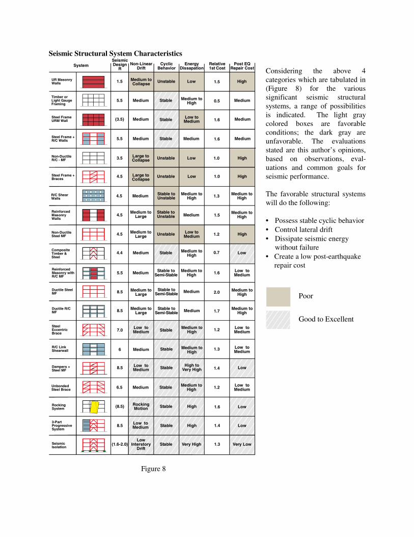
Considering the above 4 categories which are tabulated in (Figure 8) for the various significant seismic structural systems, a range of possibilities is indicated. The light gray colored boxes are favorable conditions; the dark gray are unfavorable. The evaluations stated are this author’s opinions, based on observations, eval-uations and common goals for seismic performance. The favorable structural systems will do the following: • Possess stable cyclic behavior • Control lateral drift • Dissipate seismic energy without failure • Create a low post-earthquake repair cost
Poor
Good to Excellent

THE SEARCH FOR THE PERFECT SEISMIC SYSTEM The following topics represent steps and ideas in the search for the “perfect system.” Historic Development The 100-year review of seismic systems indicates a slow development of structural solutions. In fact, most development occurs after a damaging earthquake. Perhaps this slow periodic development is due to waiting to see whether previous ideas were a success or failure. Structural Mechanisms There have been occasional conceptual break-throughs in structural thinking. For example, Dr. Ian Skinner and his team working at the New Zealand National Laboratory developed in 1976 a set of energy dissipating concepts suitable for use in seismic protection. Among the most notable concepts was the practical use of elastomeric isolation bearings for global protection of complete structures. The other concepts developed in New Zealand have also been utilized in building design. The set of five mechanisms published in 1980 were 1) Flexural Plate Device, 2) Flexural Beam Device, 3) Torsional Beam Device, 4) Lead-Rubber Device, and 5) Constricted-Tube Extrusion Energy-Absorber. Many of these relatively simple mechanisms are new to the design professions and to constructors; consequently, they represent unknown processes and unknown costs. Development and education is the key to the acceptance and adoption of these systems. Perhaps a few prototype, well-publicized projects would familiarize the design professions and constructors with the details and costs of these good ideas. To date, this has been done with the flexural plate and the lead-rubber isolation bearing. Semi-Active and Active Dampers In the recent decade, research and design work in Japan has focused on devices for structural control during wind and earthquakes. These devices are passive, active, hybrid and semi-active systems, and have been summarized by Spencer and Nagarajah. The current systems are characterized by devices which control properties and behaviors: 1) Variable-Orifice Dampers, 2) Variable-Stiffness Device, 3) Smart Tuned Mass Dampers, 4) Variable Friction Dampers and 5) Controllable Fluid Dampers. Some of these systems are in limited use, others are still in development. The goal of these devices is to respond actively to the variable character of earthquake displacements, velocity, accelerations, etc. by adding damping or altering stiffness. Conflict of the Design Approach Searching for the perfect system with conventional solutions has been limited to date because seismic forces which are based on accelerations (F=Ma), and then the resulting lateral drift or movements of the structure are reviewed to check the behavior of both structural and non-structural elements such as rigid cladding. This process has an inherent conflict. The larger the acceleration (a), the larger the seismic force (F). The larger the force (F), the stronger the structure; the stronger the structure, the stiffer the structure. The stiffer the structure, the higher the seismic acceleration, and so on. A strong, stiff structure appears to be good conceptually. The lateral drift (or horizontal displacement) is at a minimum, which is also good. The contradiction of this approach comes from seismic energy dissipation which is the fundamental need and characteristic of good seismic design; and energy dissipation results from large displacements, not small displacements.

So we need large displacements to dissipate seismic energy, and small displacements for lateral drift control to protect cladding and interior systems and partitions. This produces a conflict for most of the classic conventional structural concepts. The most useful seismic systems are those which have predictable stable, non-degrading cyclic behavior. Contemporary structures with these characteristics are base-isolation systems; moment frames with dampers; shear-link systems, such as coupled shear walls, and eccentric braced frames, and other dual-resistance systems with built-in redundancy. The most credible non-structural components are those which accommodate large lateral movements without failure. Building Configuration The one design approach in the search for the perfect system, not yet commonly pursued, is the impact of building configuration. Conventional rectangular grids are commonly used for building layout, design and construction Irregular, random, free-form grids are not yet explored. They are commonly rejected because of cost issues:
· Construction cost · Analysis cost · Design cost · Interior space cost · Efficiency of floor space (rental cost)
The potential for optimizing seismic resistance with respect to structural configuration is an obvious direction for the future. Structural form should follow the needs. How can we define seismic needs? Buildings must dissipate energy; the question is how to configure a structure to dissipate energy? Use its form or configuration. There are natural forms such as 1) buildings acting as springs, 2) rocking mechanisms, 3) flexural stories, 4) yielding links, articulated cable restrained configurations, pyramid forms, cable anchors, etc. Any system which can dissipate seismic energy without damage would be a candidate.
Figure 9

CONCLUSION
As a profession, structural engineers cannot simply wait for the devastating earthquake to occur, instead we must consider complex issues such as seismic energy dissipation and utilize realistic analysis methods to design new buildings and to modify existing structures. This is not a simple task. The variables are numerous and change for the different building types, different configurations, and different building sizes. There are numerous other variables: 1) duration of shaking, 2) frequency content of seismic motion, 3) displacement, 4) velocity, 5) acceleration, 6) direction of the earthquake pulse and proximity to an active fault, and 7) soil amplification effects. In addition to the geologic and seismic issues, each structural system has its own variables. With this vast set of variables, and the past 100 years of seismic experience, the analysis and design necessary to create a trouble free structure is still elusive. Design work today must find systems, whether structural concepts or architectural configurations, which dissipate energy in a controlled manner -- that is our challenge.