seismic, structural and lbb studies · pressure and temperature piping systems under all...
TRANSCRIPT
Seismic, Structural and LBB Studies
211 Reactor Technology & Engineering BARC HIGHLIGHTS
1 4 . S E I S M I C , S T R U C T U R A L A N D L B B S T U D I E S
I N T R O D U C T I O N
This chapter contains articles on analytical and experimental simulation for structural qualification of reactor components and systems
under normal, upset and accident conditions. Development of methodologies for meeting Leak before Break (LBB) criteria for high
pressure and temperature piping systems under all conditions, fracture studies on various piping components, generation of valuable
information by testing large piping components, analytical and experimental studies of bimetallic weld joints and development and
testing of energy absorbing devices like Elasto Plastic Dampers (EPDs) and Lead Extrusion Dampers (LEDs), are some of the important
research activities highlighted in this chapter.
Seismic, Structural and LBB Studies
212 BARC HIGHLIGHTS Reactor Technology & Engineering
14.1 CYCLIC FRACTURE INVESTIGATION ON
STRAIGHT P IPES UNDER REVERSIBLE
LOADING
The current Leak Before Break (LBB) assessment is based primarily
on the monotonic fracture tearing instability. The maximum
design accident load is compared with the fracture-tearing
resistance load. The effect of cyclic loading has generally not
been considered in the fracture assessment of nuclear power
plant piping. Indian nuclear power reactors consider Operational-
Basis-Earthquake (OBE) and Safe-Shutdown-Earthquake (SSE)
events in the design of various structures, systems and
components. It is a well-known fact that the reversible cyclic
loading decreases the fracture resistance of the material, which
leads to increased crack growth. Unlike monotonic fracture, in
cyclic fracture, the instability depends on the full load history
and on parameters such as loading ratio, loading range and
number of load cycles. A cracked component, which is safe for
monotonic load, may fail in limited number of cycles when
subjected to fully reversible cyclic load of same amplitude.
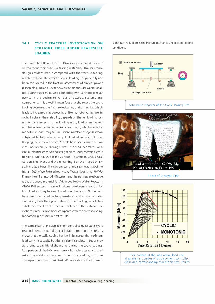
Keeping this in view a series 23 tests have been carried out on
circumferentially through wall cracked seamless and
circumferential seam welded straight pipes under reversible cyclic
bending loading. Out of the 23 tests, 15 were on SA333 Gr.6
Carbon Steel Pipes and the remaining 8 on AISI Type 304 LN
Stainless Steel Pipes. The carbon steel grade is same as that of the
Indian 500 MWe Pressurised Heavy Water Reactor’s (PHWR)
Primary Heat Transport (PHT) system and the stainless steel grade
is the proposed material for Advanced Heavy Water Reactor’s
AHWR PHT system. The investigations have been carried out for
both load and displacement controlled loadings. All the tests
have been conducted under quasi-static i.e. slow loading rates
simulating only the cyclic nature of the loading, which has
substantial effect on the fracture resistance of the material. The
cyclic test results have been compared with the corresponding
monotonic pipe fracture test results.
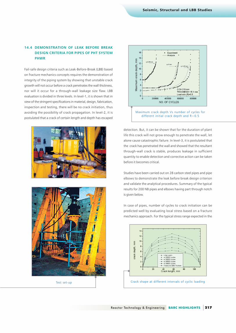
The comparison of the displacement controlled quasi-static cyclic
test and the corresponding quasi-static monotonic test results
shows that the cyclic loading has less influence on the maximum
load carrying capacity but there is significant loss in the energy
absorbing capability of the piping during the cyclic loading.
Comparision of the J-R curves from cyclic fracture tests calculated
using the envelope curve and η factor procedure, with the
corresponding monotonic test J-R curve shows that there is
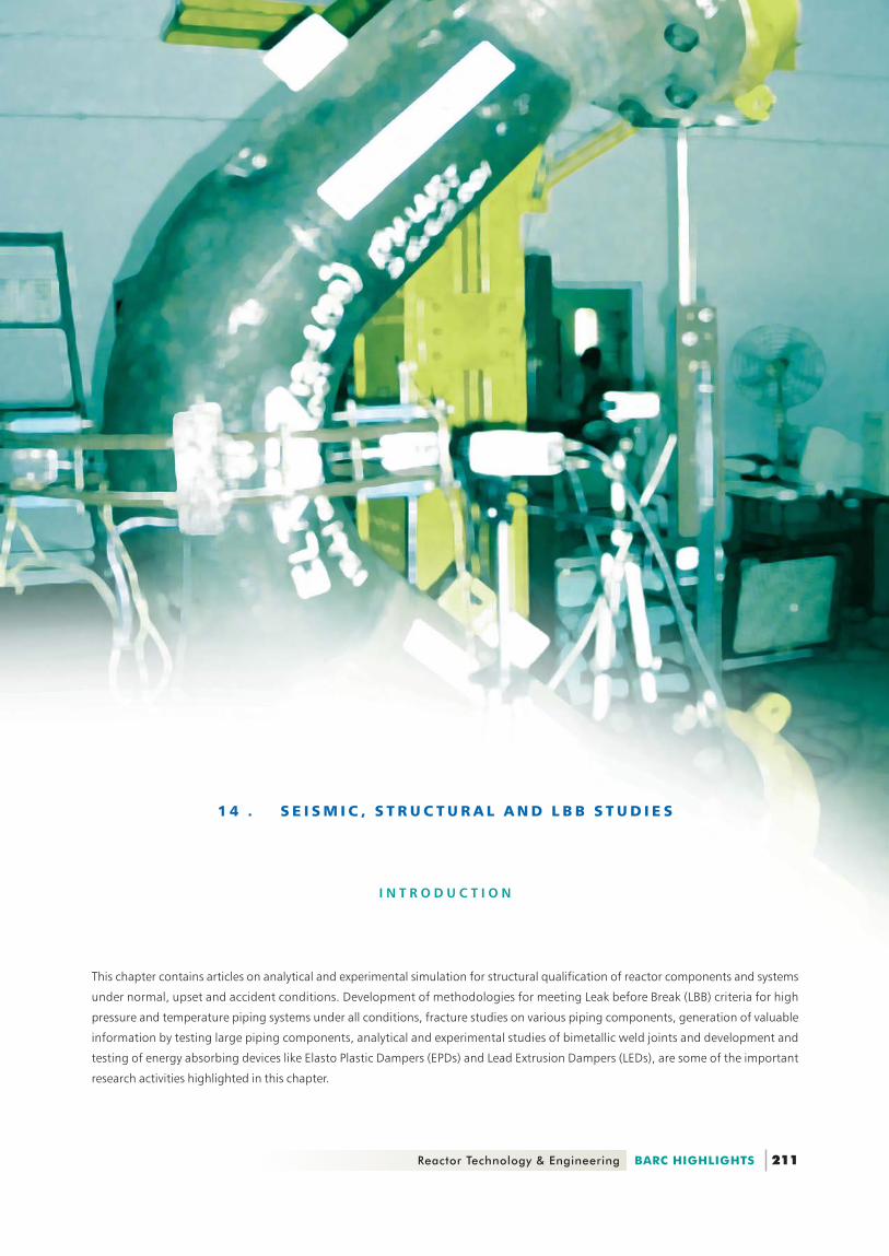
Schematic Diagram of the Cyclic Tearing Test
Image of a tested pipe
Comparison of the load versus load linedisplacement curves of displacement controlled
cyclic and corresponding monotonic test results.
significant reduction in the fracture resistance under cyclic loading
conditions.

Seismic, Structural and LBB Studies
213 Reactor Technology & Engineering BARC HIGHLIGHTS
Comparison of the J-R Curves Displacement ControlledCyclic Tearing Tests and corresponding Monotonic
Fracture Test
load cycles) in term of the percent of monotonic critical load.
For the postulated 50 cycles of high amplitude loading, the
failure load reduces to 78% of the monotonic failure load for
the base material and to 74% of the monotonic failure load for
weld material.
The crack growth in cyclic tearing consists two parts, one is
crack growth due to low cycle fatigue and the other is due to
static tearing. Few load-controlled tests have been investigated
in detail with the objective to establishing a methodology for
prediction of instability and failure life under fully reversible cyclic
loads. In the study crack growth by both, fatigue (under large
scale yielding i.e. Low Cycle Fatigue Crack Growth) and static
fracture have been considered. The cycle-by-cycle crack growth
contribution by both the modes has been calculated and then
accumulated predicted crack growth has been plotted against
number of cycles.
Normalised Load Amplitude versus Numberof load cycles to fail (Nf) curves Load
Controlled cyclic tests having Load ratio –1.
Crack growth ‘Δa’ versus Number ofcycles for load controlled cyclic
tearing tests ‘QCSP-8-60-L2-CSB
Suneel Gupta, <[email protected]>
The load controlled quasi-static cyclic tests shows the importance
of the number of the load cycles in the fracture assessment of
piping subjected to cyclic loading event. The cyclic fracture tests
have shown that the pipes may fail in limited number of load
cycles with the load amplitude sufficiently below the monotonic
fracture/collapse load . A simplified material specific (for SA333Gr6
carbon steel) master curve has been generated directly from
these pipe cyclic tearing tests. The master curve is the plot of the
cyclic load amplitude (given as % of maximum load recorded in
corresponding monotonic fracture test) versus number of load
cycles to fail (Nf). This curve can readily be used in the current
pract ice for LBB qual i f icat ion for evaluat ing the
critical load (which accounts for cyclic damage and number of
These experiments highlight the need of modifying the current
LBB design rules (i.e. allowable load limits for peak dynamic loads
at various postulated crack locations) to make the LBB design
more realistic.

Seismic, Structural and LBB Studies
214 BARC HIGHLIGHTS Reactor Technology & Engineering
14.2 FRACTURE EXPERIMENTS ON P IP ING
COMPONENTS
Leak-Before-Break (LBB) concept is now universally used to
design the Primary Heat Transport (PHT) piping of the
Pressurized Heavy Water Reactors (PHWR). The same is being
followed to design the newly built Indian PHWRs. This concept
aims at the application of fracture mechanics principle to
demonstrate that pipes are unlikely to experience catastrophic
break without prior indication of leakage. This requires detailed
fracture mechanics analysis of different piping components e.g.
straight pipes, elbows and branch tees. There are several issues in
fracture mechanics analysis that requires experimental
validation, for example, transferability of specimen fracture
resistance data to component level, method of extrapolation of
fracture resistance curve beyond test range, lack of sufficient
elbow fracture test data to validate various new developments.
Against this background, a comprehensive Component Integrity
Test Program was initiated to address these unresolved issues.
Total 45 fracture tests were carried out at SERC, Chennai on
27 pipes and 18 elbows made of PHT carbon steel material
SA333Gr6 of 8-16 inch diameter with various crack
configurations subjected to bending moment loading.
During the fracture experiments, load, load line displacement,
crack growth, crack opening displacement at various locations
of the notch were measured continuously during experiments.
A new image processing system SPIAS was developed to measure
crack growth during fracture experiments.
Figures show the experimental set up for fracture tests and
also some typical out-of-plane crack growth in carbon steel
pipes and elbows. Figures also show the role of stress tri-axiality
in the transfer of J-R curve from small laboratory specimen
to component. These test results form a valuable database
for exper imental va l idat ion of any new theoret ica l
developments in future related to the integrity assessment
methodology of piping components.
Photograph of pipe fracture test
Typical out-of-plane crack growth in carbon steel pipe
Crack growth in a surface cracked pipe incarbon steel pipe
Elbow fracture test set up

Seismic, Structural and LBB Studies
215 Reactor Technology & Engineering BARC HIGHLIGHTS
14.3 PROPOSING NEW EQUATIONS TO
EVALUATE FRACTURE PARAMETERS OF
PIPING COMPONENTS
Simple analytical formula to evaluate fracture parameters of
components often simplifies the integrity assessment. While many
formulae are available for pipes, very few are available for one of
the important piping components, namely, elbows. These
equations are especially useful for Leak-Before-Break
calculations of PHT piping components of Indian PHWR.
Crack opening of a throughwall-crackedelbow in carbon steel pipe
Variation of stress-triaxiality (Anq) near crack tipwith crack driving force (J-integral)
Identical J-R curves of specimens, pipes andelbows having identical stress-triaxiality
Dr.J.Chattopadhyay, <[email protected]>
New closed-form equations have been proposed for the following
cases :
..... To evaluate stress intensity factors of throughwall cracked
elbow under combined internal pressure and bending
moment. These equations were recommended by
European Structural Integrity code SINTAP for integrity
assessment of cracked elbows.
..... To evaluate limit moment of throughwall circumferentially
cracked elbows under in-plane closing and opening
bending moments.
..... To estimate elastic-plastic J-integral and Crack Opening
Displacement (COD) of throughwall circumferentially
cracked elbow under closing moment.
..... To evaluate limit moment of defect-free elbows under
combined internal pressure and bending moment.
Surface plot of weakening factor (symbolsshow the FE data points and wire mesh
shows the smoothened surface)

Seismic, Structural and LBB Studies
216 BARC HIGHLIGHTS Reactor Technology & Engineering
All these newly proposed equations have been validated with the
experimental data, generated under Component Integrity Test
Program and also available in the literature. Large number of
research papers have been published in international journals
based on these works.
Figure shows the surface plot of weakening factor (ML/Mo), crack
angle (2θ) and radius to thickness (R/t) ratio for throughwall
circumferentially cracked elbows subjected to closing bending
moment. Table and figure show the comparison of test data
with the predictions of the newly proposed closed-form
equations.
Comparison of test data with predictions of thenewly proposed Crack Opening Displacement (COD)
estimation scheme for throughwallcircumferentially cracked elbow under closing moment
J.Chattopadhyay, <[email protected]>
..... Limit load based general expressions of ‘η’ and ‘γ’
functions to evaluate fracture resistance (J-R) curve from
test data.
Comparison of experimental collapse moments with theoretical predictions(The bracketed numbers indicate the percentage difference with
respect to experimental values)
Seismic, Structural and LBB Studies
217 Reactor Technology & Engineering BARC HIGHLIGHTS
14.4 DEMONSTRATION OF LEAK BEFORE BREAK
DESIGN CRITERIA FOR PIPES OF PHT SYSTEM
PHWR
Fail-safe design criteria such as Leak-Before-Break (LBB) based
on fracture mechanics concepts requires the demonstration of
integrity of the piping system by showing that unstable crack
growth will not occur before a crack penetrates the wall thickness,
nor will it occur for a through-wall leakage size flaw. LBB
evaluation is divided in three levels. In level-1, it is shown that in
view of the stringent specifications in material, design, fabrication,
inspection and testing, there will be no crack initiation, thus
avoiding the possibility of crack propagation. In level-2, it is
postulated that a crack of certain length and depth has escaped
Test set-up
detection. But, it can be shown that for the duration of plant
life this crack will not grow enough to penetrate the wall, let
alone cause catastrophic failure. In level-3, it is postulated that
the crack has penetrated the wall and showed that the resultant
through-wall crack is stable, produces leakage in sufficient
quantity to enable detection and corrective action can be taken
before it becomes critical.
Studies have been carried out on 28 carbon steel pipes and pipe
elbows to demonstrate the leak before break design criterion
and validate the analytical procedures. Summary of the typical
results for 200 NB pipes and elbows having part through notch
is given below.
In case of pipes, number of cycles to crack initiation can be
predicted well by evaluating local stress based on a fracture
mechanics approach. For the typical stress range expected in the
Maximum crack depth Vs number of cycles fordifferent initial crack depth and R=0.5
Crack shape at different intervals of cyclic loading
Seismic, Structural and LBB Studies
218 BARC HIGHLIGHTS Reactor Technology & Engineering
piping of PHWR, the number of cycles to crack initiation is very
large compared to the expected number of cycles. Paris constants
obtained from the standard specimens can be used directly for
crack growth rate analysis of pipes. The use of the fatigue crack
growth curve given in ASME Section XI will produce a conservative
result. Even after crack initiation, the number of cycles required
for the crack to grow through-wall is enormously large thus
satisfying LBB level-2 criteria. The ratio of moment required to
cause instability to the moment expected during SSE is more
than √2, thus
satisfying the LBB
level-3 criterion.
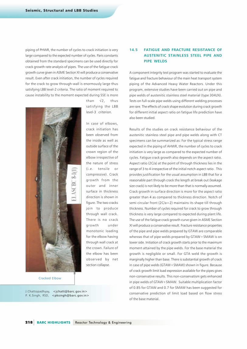
In case of elbows,
crack initiation has
been observed from
the inside as well as
outside surface of the
crown region of the
elbow irrespective of
the nature of stress
( i .e . tens i le or
compressive). Crack
growth from the
outer and inner
surface in thickness
direction is shown in
figure. The two cracks
join to produce
through wall crack.
There is no crack
growth under
monotonic loading
for the elbow having
through wall crack at
the crown. Failure of
the elbow has been
observed by net
section collapse.
Cracked Elbow
14.5 FATIGUE AND FRACTURE RESISTANCE OF
AUSTENITIC STAINLESS STEEL PIPE AND
PIPE WELDS
A component integrity test program was started to evaluate the
fatigue and fracture behaviour of the main heat transport system
piping of the Advanced Heavy Water Reactors. Under this
program, extensive studies have been carried out on pipe and
pipe welds of austenitic stainless steel material (type 304LN).
Tests on full-scale pipe welds using different welding processes
are rare. The effects of crack shape evolution during crack growth
for different initial aspect ratio on fatigue life prediction have
also been studied.
Results of the studies on crack resistance behaviour of the
austenitic stainless steel pipe and pipe welds along with CT
specimens can be summarized as: For the typical stress range
expected in the piping of AHWR, the number of cycles to crack
initiation is very large as compared to the expected number of
cycles. Fatigue crack growth also depends on the aspect ratio.
Aspect ratio (2C/a) at the point of through thickness lies in the
range of 3 to 4 irrespective of the initial notch aspect ratio . This
provides justification for the usual assumption in LBB that for a
reasonable part through crack the length at break out (leakage
size crack) is not likely to be more than that is normally assumed.
Crack growth in surface direction is more for the aspect ratio
greater than 4 as compared to thickness direction. Notch of
semi circular front (2C/a=2) maintains its shape till through
thickness. Number of cycles required for crack to grow through
thickness is very large compared to expected during plant life.
The use of the fatigue crack growth curve given in ASME Section
XI will produce a conservative result. Fracture resistance properties
of the pipe and pipe welds prepared by GTAW are comparable
whereas that of pipe welds prepared by GTAW+SMAW is on
lower side. Initiation of crack growth starts prior to the maximum
moment attained by the pipe welds. For the base material the
growth is negligible or small. For GTA weld the growth is
marginally higher than base. There is substantial growth of crack
in case of pipe welds (GTAW+SMAW) shown in figure. Because
of crack growth limit load expression available for the pipes gives
non-conservative results. This non-conservatism gets enhanced
in pipe welds of GTAW+SMAW. Suitable multiplication factor
of 0.85 for GTAW and 0.7 for SMAW has been suggested for
conservative prediction of limit load based on flow stress
of the base material.
J.Chattopadhyay, <[email protected]>P. K.Singh, RSD, <[email protected]>

Seismic, Structural and LBB Studies
219 Reactor Technology & Engineering BARC HIGHLIGHTS
Comparison of crack growth curveVariation of aspect ratio with crack growth
Fracture surface showing crack shape
Comparison of crack growth ratecurve from pipe and ASME
Comparison of bending rotation forpipe and pipe welds
Comparison of tearing propertyof pipe and pipe welds
Seismic, Structural and LBB Studies
220 BARC HIGHLIGHTS Reactor Technology & Engineering
Crack growth in base (300NB)
Crack growth in weld (GTAW+SMAW,300NB)
Crack growth in base (150NB)
Crack growth in weld (GTAW 150NB)
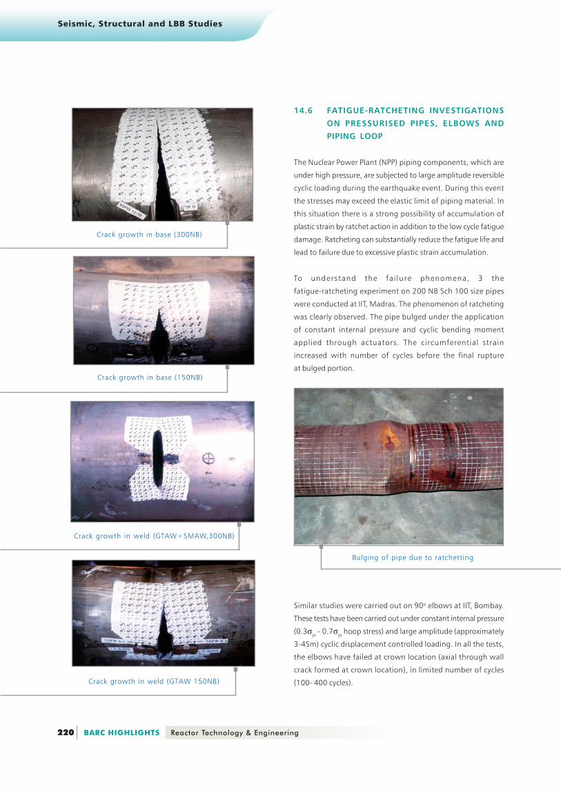
14.6 FATIGUE-RATCHETING INVESTIGATIONS
ON PRESSURISED PIPES, ELBOWS AND
PIPING LOOP
The Nuclear Power Plant (NPP) piping components, which are
under high pressure, are subjected to large amplitude reversible
cyclic loading during the earthquake event. During this event
the stresses may exceed the elastic limit of piping material. In
this situation there is a strong possibility of accumulation of
plastic strain by ratchet action in addition to the low cycle fatigue
damage. Ratcheting can substantially reduce the fatigue life and
lead to failure due to excessive plastic strain accumulation.
To understand the fa i lure phenomena, 3 the
fatigue-ratcheting experiment on 200 NB Sch 100 size pipes
were conducted at IIT, Madras. The phenomenon of ratcheting
was clearly observed. The pipe bulged under the application
of constant internal pressure and cyclic bending moment
applied through actuators. The circumferential strain
increased with number of cycles before the final rupture
at bulged portion.
Similar studies were carried out on 90o elbows at IIT, Bombay.
These tests have been carried out under constant internal pressure
(0.3σys - 0.7σys hoop stress) and large amplitude (approximately
3-4Sm) cyclic displacement controlled loading. In all the tests,
the elbows have failed at crown location (axial through wall
crack formed at crown location), in limited number of cycles
(100- 400 cycles).
Bulging of pipe due to ratchetting
Seismic, Structural and LBB Studies
221 Reactor Technology & Engineering BARC HIGHLIGHTS
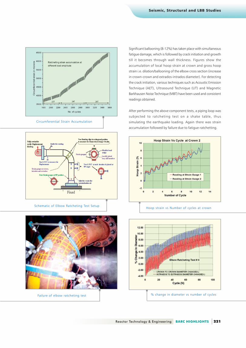
Significant ballooning (8-12%) has taken place with simultaneous
fatigue damage, which is followed by crack initiation and growth
till it becomes through wall thickness. Figures show the
accumulation of local hoop strain at crown and gross hoop
strain i.e. dilation/ballooning of the elbow cross section (increase
in crown-crown and extrados-intrados diameter). For detecting
the crack initiation, various techniques such as Acoustic Emission
Technique (AET), Ultrasound Technique (UT) and Magnetic
Barkhausen Noise Technique (MBT) have been used and consistent
readings obtained.
After performing the above component tests, a piping loop was
subjected to ratcheting test on a shake table, thus
simulating the earthquake loading. Again there was strain
accumulation followed by failure due to fatigue-ratchetting.
Circumferential Strain Accumulation
Schematic of Elbow Ratcheting Test Setup
Failure of elbow ratcheting test
Hoop strain vs Number of cycles at crown
% change in diameter vs number of cycles
Seismic, Structural and LBB Studies
222 BARC HIGHLIGHTS Reactor Technology & Engineering
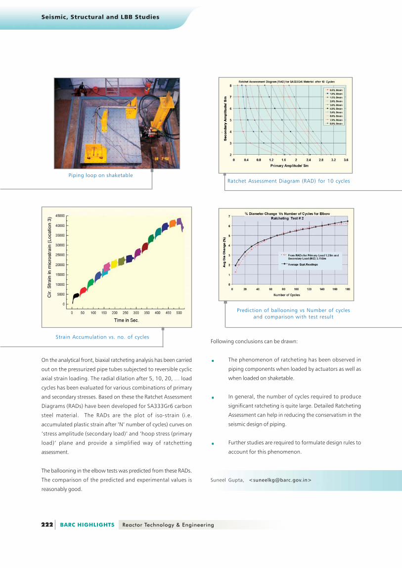
On the analytical front, biaxial ratcheting analysis has been carried
out on the pressurized pipe tubes subjected to reversible cyclic
axial strain loading. The radial dilation after 5, 10, 20, … load
cycles has been evaluated for various combinations of primary
and secondary stresses. Based on these the Ratchet Assessment
Diagrams (RADs) have been developed for SA333Gr6 carbon
steel material. The RADs are the plot of iso-strain (i.e.
accumulated plastic strain after ‘N’ number of cycles) curves on
‘stress amplitude (secondary load)’ and ‘hoop stress (primary
load)‘ plane and provide a simplified way of ratchetting
assessment.
The ballooning in the elbow tests was predicted from these RADs.
The comparison of the predicted and experimental values is
reasonably good.
Piping loop on shaketable
Strain Accumulation vs. no. of cyclesFollowing conclusions can be drawn:
..... The phenomenon of ratcheting has been observed in
piping components when loaded by actuators as well as
when loaded on shaketable.
..... In general, the number of cycles required to produce
significant ratcheting is quite large. Detailed Ratcheting
Assessment can help in reducing the conservatism in the
seismic design of piping.
..... Further studies are required to formulate design rules to
account for this phenomenon.
Ratchet Assessment Diagram (RAD) for 10 cycles
Prediction of ballooning vs Number of cyclesand comparison with test result
Suneel Gupta, <[email protected]>

Seismic, Structural and LBB Studies
223 Reactor Technology & Engineering BARC HIGHLIGHTS
14.7 RATCHETING STUDIES OF P IP ING
MATERIALS FOR NUCLEAR POWER PLANTS
Ratcheting is defined as the accumulation of strain during
asymmetrical stress cycling in a material. This is quite significant
as for a suitable combination of mean and cyclic loads there can
be large deformations in the structure. In piping materials, even
at room temperature significant ratcheting strain accumulation
has been found both at specimen level and in actual piping
component. The seismic design aspect of piping components
receives high importance and is met through a conservative design
practice, which leads to increase in cost of building nuclear
facilities. It has therefore been realized that in order to develop
realistic design code rules ensuring safety against seismic loads
experimental ratcheting data needs to be determined. PHWR
and the proposed AHWR have an elaborate piping network to
cater to the PHT requirements of the respective nuclear reactors.
They are primarily made up of SA 106 B and SA 333 Gr 6 for the
old and new PHWR respectively and 304L for AHWR. Ratcheting
studies are being carried out on the above mentioned materials
both at the lab specimen and component level. The objective of
the studies is to determine the most important factors leading
to ratcheting, derive design criteria based on experiments and
finally validation of design in component level tests. Finite Element
Analysis and modeling based on various coupled kinematic
hardening rules will be also used to predict the ratcheting
behavior.
An experiment has been conducted on a straight pipe subjected
to internal pressure and cyclic bending load. Cyclic bending load
has been applied to the pipe in three point and four point bend
test configurations. Finite Element Analysis also has been carried
out to simulate ratcheting phenomenon. The pipe is modeled
using large strain plastic shell element and analyzed for constant
internal pressure. Chaboche non-linear kinematic hardening model
is used for predicting ratcheting response.
��� ������������ ������� ��� ���������� �������
Hoop strain vs. Number of Cycles for 3-point bend test on straight pipe
Seismic, Structural and LBB Studies
224 BARC HIGHLIGHTS Reactor Technology & Engineering
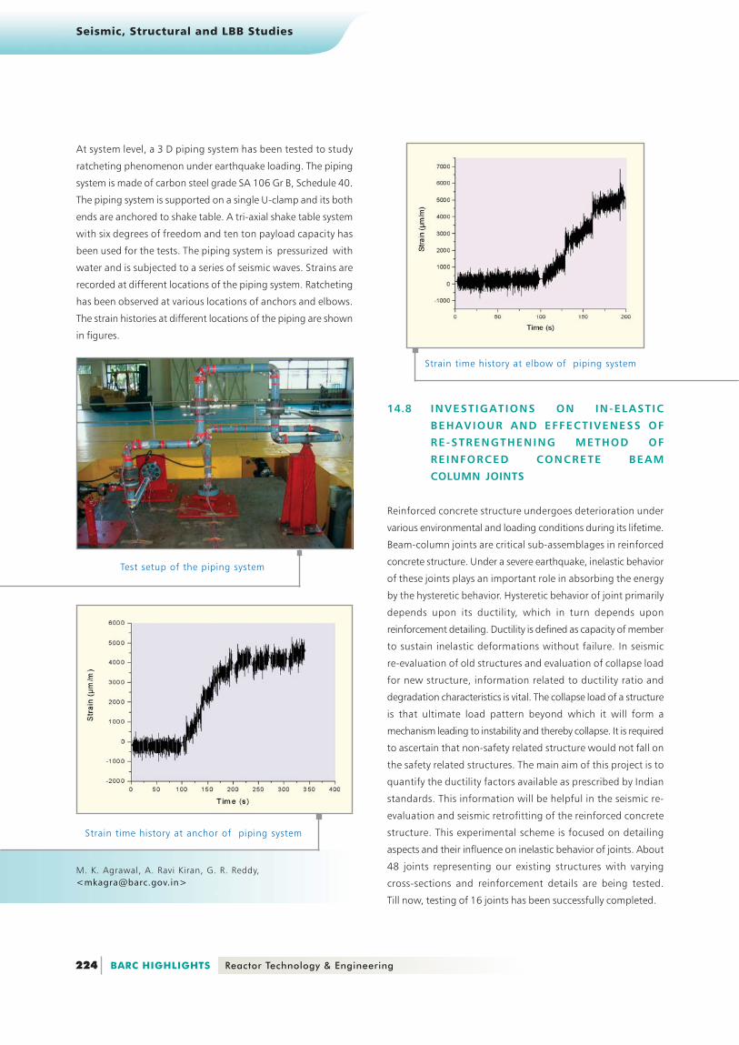
At system level, a 3 D piping system has been tested to study
ratcheting phenomenon under earthquake loading. The piping
system is made of carbon steel grade SA 106 Gr B, Schedule 40.
The piping system is supported on a single U-clamp and its both
ends are anchored to shake table. A tri-axial shake table system
with six degrees of freedom and ten ton payload capacity has
been used for the tests. The piping system is pressurized with
water and is subjected to a series of seismic waves. Strains are
recorded at different locations of the piping system. Ratcheting
has been observed at various locations of anchors and elbows.
The strain histories at different locations of the piping are shown
in figures.
Test setup of the piping system
Strain time history at anchor of piping system
Strain time history at elbow of piping system
M. K. Agrawal, A. Ravi Kiran, G. R. Reddy,<[email protected]>
14.8 INVEST IGATIONS ON IN-ELAST IC
BEHAVIOUR AND EFFECTIVENESS OF
RE-STRENGTHENING METHOD OF
REINFORCED CONCRETE BEAM
COLUMN JOINTS
Reinforced concrete structure undergoes deterioration under
various environmental and loading conditions during its lifetime.
Beam-column joints are critical sub-assemblages in reinforced
concrete structure. Under a severe earthquake, inelastic behavior
of these joints plays an important role in absorbing the energy
by the hysteretic behavior. Hysteretic behavior of joint primarily
depends upon its ductility, which in turn depends upon
reinforcement detailing. Ductility is defined as capacity of member
to sustain inelastic deformations without failure. In seismic
re-evaluation of old structures and evaluation of collapse load
for new structure, information related to ductility ratio and
degradation characteristics is vital. The collapse load of a structure
is that ultimate load pattern beyond which it will form a
mechanism leading to instability and thereby collapse. It is required
to ascertain that non-safety related structure would not fall on
the safety related structures. The main aim of this project is to
quantify the ductility factors available as prescribed by Indian
standards. This information will be helpful in the seismic re-
evaluation and seismic retrofitting of the reinforced concrete
structure. This experimental scheme is focused on detailing
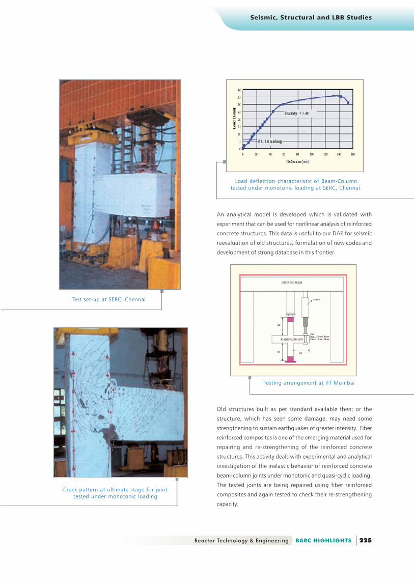
aspects and their influence on inelastic behavior of joints. About
48 joints representing our existing structures with varying
cross-sections and reinforcement details are being tested.
Till now, testing of 16 joints has been successfully completed.
Seismic, Structural and LBB Studies
225 Reactor Technology & Engineering BARC HIGHLIGHTS
An analytical model is developed which is validated with
experiment that can be used for nonlinear analysis of reinforced
concrete structures. This data is useful to our DAE for seismic
reevaluation of old structures, formulation of new codes and
development of strong database in this frontier.
Test set-up at SERC, Chennai
Crack pattern at ultimate stage for jointtested under monotonic loading
Load deflection characteristic of Beam-Columntested under monotonic loading at SERC, Chennai.
Testing arrangement at IIT Mumbai
Old structures built as per standard available then; or the
structure, which has seen some damage, may need some
strengthening to sustain earthquakes of greater intensity. Fiber
reinforced composites is one of the emerging material used for
repairing and re-strengthening of the reinforced concrete
structures. This activity deals with experimental and analytical
investigation of the inelastic behavior of reinforced concrete
beam-column joints under monotonic and quasi-cyclic loading.
The tested joints are being repaired using fiber reinforced
composites and again tested to check their re-strengthening
capacity.
Seismic, Structural and LBB Studies
226 BARC HIGHLIGHTS Reactor Technology & Engineering
Elasto-plastic dampers were fabricated and tested for its
characteristics. . . . . Shake table tests were performed on piping
Comparison of test and analysisresponse of piping system with EPD
Experimental Results of joint under quasicyclic loading conducted at IIT, Mumbai
K.N. Vaity, <[email protected]>
14.9 ENERGY ABSORBING DEVICES FOR
SEISMIC RESPONSE REDUCTION
One of the ways of reducing seismic response is by using snubbers,
which permit low thermal movement but arrest the fast seismic
movement. However, snubbers are costly and require periodic
maintenance. Therefore there is thinking in favour of using energy
absorbers in place of snubbers to reduce the seismic response in
PHWR equipment and piping systems. Energy absorbers like
Elasto-Plastic Dampers (EPDs) and Lead Extrusion Dampers (LEDs)
absorb large part of vibration energy and lesser energy is
transmitted to piping systems and equipment.
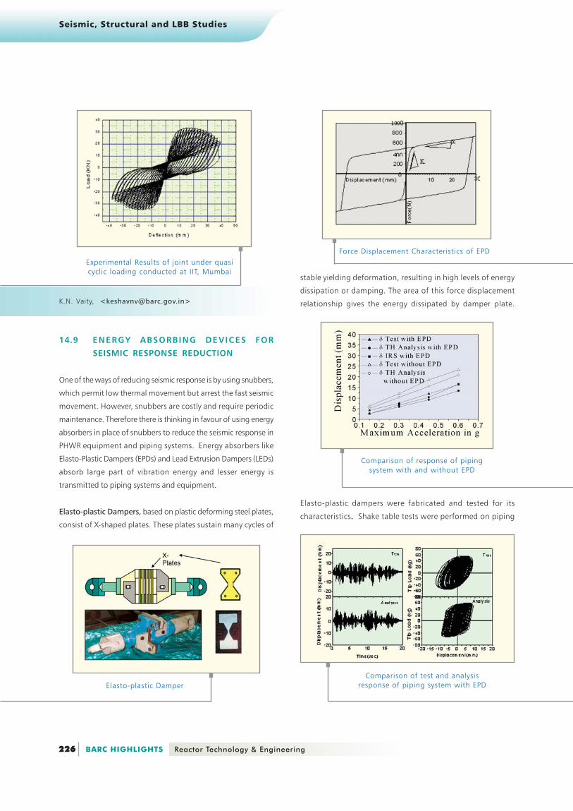
Elasto-plastic Dampers, based on plastic deforming steel plates,
consist of X-shaped plates. These plates sustain many cycles of
stable yielding deformation, resulting in high levels of energy
dissipation or damping. The area of this force displacement
relationship gives the energy dissipated by damper plate.
Elasto-plastic Damper
Force Displacement Characteristics of EPD
Comparison of response of pipingsystem with and without EPD
Seismic, Structural and LBB Studies
227 Reactor Technology & Engineering BARC HIGHLIGHTS
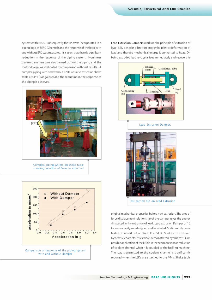
systems with EPDs. Subsequently the EPD was incorporated in a
piping loop at SERC (Chennai) and the response of the loop with
and without EPD was measured. It is seen that there is significant
reduction in the response of the piping system. Nonlinear
dynamic analysis was also carried out on the piping and the
methodology was validated by comparison with test results . A
complex piping with and without EPDs was also tested on shake
table at CPRI (Bangalore) and the reduction in the response of
the piping is observed.
Complex piping system on shake tableshowing location of Damper attached
Comparison of response of the piping systemwith and without damper
Lead Extrusion Damper.
Test carried out on Lead Extrusion
Lead Extrusion Dampers work on the principle of extrusion of
lead. LED absorbs vibration energy by plastic deformation of
lead and thereby mechanical energy is converted to heat. On
being extruded lead re-crystallizes immediately and recovers its
original mechanical properties before next extrusion. The area of
force displacement relationship of the damper gives the energy
dissipated in the extrusion of lead. Lead extrusion Damper of 15
tonnes capacity was designed and fabricated. Static and dynamic
tests are carried out on the LED at SERC Madras. The desired
hysteretic characteristics were demonstrated by this test. One
possible application of the LED is in the seismic response reduction
of coolant channel when it is coupled to the fuelling machine.
The load transmitted to the coolant channel is significantly
reduced when the LEDs are attached to the F/Ms. Shake table

Seismic, Structural and LBB Studies
228 BARC HIGHLIGHTS Reactor Technology & Engineering
Hysteretic Force displacement characteristicsof LED (Theoretical and Experimental)
Y.M. Parulekar, <[email protected]>
14.10 STRUCTURAL INTEGRITY ASSESSMENT
OF BIMETALLIC WELDED JOINTS
Structural integrity assessment of Bi-Metallic Welds (BMW) is an
important issue for the power plant and process industry.
Bi-metallic joints are often used to connect ferritic pressure
vessel nozzles or ferritic piping with austenitic piping. Recent
international surveys of such welded joints have shown that
there are several cracking problems, due to fabrication induced
defects, ageing, corrosion or thermal fatigue caused by
temperature changes during service life of plant. Defects in
structural components often occur within or near welds across
which tensile properties may vary significantly. This mismatch in
tensile properties can affect the plastic deformation pattern of
the defective component and hence the crack driving force such
as the J-integral or the crack tip opening displacement.
Structural integrity assessment methods for homogeneous
structures can be applied to welded structures if the tensile
properties of the weakest material are used. However such a
simplified approach can lead to an unduly conservative result.
Conventional defect assessment methods such as R6 and
GE/EPRI etc. have been modified to incorporate strength
mismatch effects. All these defect assessment procedures
require an accurate estimate of the limit load.
In BARC, comprehensive studies were performed at the
specimen level. The classical upper bound approach of limit
analysis was modified to include the presence of compressive
zones in specimens subjected to predominant bending load.
Theoretical plane-strain solutions were obtained for standard
SENB, TPB and CT specimens and were compared with the
classical slip-line field solutions. In order to determine the
fracture properties, experiments were performed on cracked
specimen to obtain their load-deflection behaviour. This load
deflection curve is then converted into J-R curve with the help
of plastic eta (ηp) functions. For the case of homogeneous
specimens eta functions are available in ASTM (E 813-88)
standards. The theoretical solutions obtained from the
developed modified upper bound approach reveals that
compared with the η-factor for a homogeneous specimen a soft
under-matched weld will increase it while a hard over-matched
weld will decrease its value. This observation is in accordance
with the findings of other researchers working in this area. This
means that the current J-integral estimation equations may
underestimate the J-integral for under-matched welds but will
over-estimate them for over-matched welds. The modified
upper bound approach was also used to obtain accurate plastic
rotation factors (rp) for bi-metallic specimens like SENB, TPB and
CT specimens. These plastic rotation factors would be used to
obtain CMOD based eta functions (ηCMOD) as they provide a more
robust and accurate J-estimation. The developed limit load
Existing conservatism in the traditional approach
solutions of bi-metallic specimens were used to obtain the
equivalent homogeneous model. This equivalent stress-strain
curve can then be used in the available defect assessment
procedures or Finite Element Analysis to evaluate crack driving
force like J-integral or crack tip opening displacement. A typical
tests are planned on vessels restrained by Lead Extrusion Dampers.

Seismic, Structural and LBB Studies
229 Reactor Technology & Engineering BARC HIGHLIGHTS
comparison of the J-integral obtained from the equivalent
stress-strain relationship to that obtained by using the
conventional approach is indicated in the above figure.
In past two decades considerable work has been done in the
area of integrity assessment of cracked welded fracture
mechanics specimens. However, no such comprehensive work
has yet been done regarding the
assessment of cracked
welded pipe joints. Conventional
welding procedures are
designed to achieve over-match
that provides a shielding effect
on the base metal . This i s
important in so far as the weld
propert ies can be less wel l
controlled as compared to the
base metal. In order to understand
the mechanics and development
of plasticity pattern in cracked
welded pipes priority was given
to over-matched welded pipes.
Since limit load solutions are
already available for various
specimens, efforts were made to develop the limit load solution
of cracked welded pipe joints from those of bi-metallic specimens.
The basic issue in developing the limit load solution is to make
equivalence between the geometrical characteristics of a pipe
and those of a specimen. Using an analogy with three point
bend specimen, the limit load of a welded pipe having a through
wall circumferential crack has been obtained.
Cracked Welded Pipe
From the experience gained at the
specimen level i t can be
concluded that for an over-matched
weld plasticity development is more
in the base material. Since the
adjacent base material dissipate
a large amount of energy during
plastic deformation the standard
ASTM (E 813-88) procedure is likely
to give much higher fracture
toughness. This higher “apparent
fracture toughness” does not
represent the real loading which
the crack tip is subjected to. As a
result, there is a need to develop new solutions of plastic eta
functions (ηp) for cracked bi-metallic pipe so that correct fracture
toughness can be obtained experimentally. In an under matched
weld plastic strains get concentrated within the weld and thus
the crack driving force is high. Narrow gap weld can reduce this
mismatch effect if under matching is mild. However if under
matching is too severe than a very high constraint would be at
the crack tip due to the adjacent harder material and thin welds
I.A. Khan, V. Bhasin, K.K. Vaze, A.K. Ghosh, H.S. Kushwaha,<[email protected]>
would be more detrimental and may show a brittle failure.