seismic stratigraphy of palmer deep: a fault-bounded late ...earthsci.fullerton.edu/kirby/rebesco et...
TRANSCRIPT

ELSEVIER Marine Geology 151 (1998) 89–110
Seismic stratigraphy of Palmer Deep:a fault-bounded late Quaternary sediment trap on the inner continental
shelf, Antarctic Peninsula Pacific margin
M. Rebesco a,Ł, A. Camerlenghi a, L. De Santis a, E. Domack b, M. Kirby c
a Osservatorio Geofisico Sperimentale, Dept. of Geophysics of the Lithosphere, Trieste, Italyb Hamilton College, Dept. of Geology, Clinton, New York, USA
c Syracuse University, Dept. of Geology, Syracuse, New York, USA
Received 16 October 1997; accepted 15 May 1998
Abstract
The Palmer Deep is an enclosed bathymetric depression on the inner portion of the Antarctic Peninsula continentalshelf about 30 km southwest of Anvers Island. Three sub-basins, separated by bathymetric sills, comprise the PalmerDeep: Basin I, Basin II, and Basin III. Deep-tow boomer seismic reflection data reveal thick (>50 m) sediment sections ineach basin consisting of Holocene diatomaceous mud. The boomer records proved fine-scale resolution of decimetre thicksediment layers within the uppermost (Holocene) seismic unit. Deeper penetration GI and small airgun records obtained in1997 provide insight into the structural and depositional history of the basins which extends clearly back in time before theHolocene (unit imaged by the boomer records). The Palmer Deep contains a sediment infill estimated at about 270 m thickarranged in a complex (five unit) internal stratigraphy unusual for the inner continental shelf of Antarctica. Combined use ofthe boomer and airgun sources allows complementary resolution of both deep and shallow stratigraphy with some reflectorscommon in both records, such as the Middle Basin Reflector at 45 ms twt below seafloor. The Middle Basin Reflector mostlikely is of latest Pleistocene age (isotopic Stage 2) and therefore 80% of the basin fill pre-dates the classic Last GlacialMaximum. The Palmer Deep is bounded by active extensional faults as evidenced by offset and stratigraphic growth withinHolocene sections. To accommodate shelf-wide glaciation on the Pacific margin of the Antarctic Peninsula we suggest asubglacial and subaqueous origin for much of the Palmer Deep basin fill. Hence, the Palmer Deep basins were the locus ofsubglacial ‘lakes’ beneath the ice sheet at times of glacial maximum. 1998 Elsevier Science B.V. All rights reserved.
Keywords: Antarctic Peninsula; high-resolution seismic stratigraphy; Holocene; glaciomarine sediments; subglacial lakes
1. The Palmer Deep
The region known as the Palmer Deep and asdescribed in detail by Kirby et al. (1998) is locatedon the inner continental shelf west of the Antarctic
Ł Corresponding author. Fax: C39 40 327307; E-mail:[email protected]
Peninsula, just south of Anvers Island, in corre-spondence with the projection of the South AnversFracture Zone (Larter et al., 1997) (Fig. 1). Thisfracture zone belongs to a set of northwesterly trans-form faults separating segments of ridge-crest thatprogressively migrated into the trench during theCenozoic and originated the thermal uplift followedby a long-term subsidence of the margin (Herron and
0025-3227/98/$ – see front matter 1998 Elsevier Science B.V. All rights reserved.PII S 0 0 2 5 - 3 2 2 7 ( 9 8 ) 0 0 0 5 7 - 7

90 M. Rebesco et al. / Marine Geology 151 (1998) 89–110
Fig. 1. Bathymetry and location of the study area. Depths in uncorrected metres. Contoured from a compilation of soundings from theANTOSTRAT and NOAA data bases (Rebesco et al., 1998).
Tucholke, 1976; Larter and Barker, 1991). Tectonicsegmentation of the Antarctic Peninsula and its offly-ing islands along the projections of these traversefracture zones has been suggested by Hawkes (1981).The region is now essentially aseismic, though activeshortening is occurring in the South Shetland Trenchsome 300 km to the northeast (Kim et al., 1995).
The Palmer Deep consists of a linear system ofthree basins oriented in a SW–NE direction (Fig. 2).The deepest and largest of these is referred to asBasin III (¾1400 m uncorrected water depth); asmaller basin (II) appears to be an extension ofBasin III at a similar depth, while the shallowestand smallest is Basin I, at just over 1000 m waterdepth. The three seafloor depressions are filled with alayered sedimentary succession that in cross-sectionattains an asymmetric V-shape rather than a U-shapeor symmetrical geometry.
Piston cores have shown that the uppermost sedi-ments of Basins II and III are mud turbidites from the
basin walls, while Basin I contains laminated mudscomposed of alternations between siliceous biogenicpelagic and siliciclastic hemipelagic sediments. Sed-iment accumulation rates ranging between 0.13 and0.24 cm=yr have been calculated for this upper unitbased on 14C dating on sediment cores (Leventer etal., 1996), so that, by extrapolation down section, thebasins are thought to contain an ultra-high resolutionsedimentary record of the Holocene down to at leastthe Last Glacial Maximum (LGM).
It is within this general framework that wepresent below the detailed observations of the shal-low and deeper seismic stratigraphy within each ofthe Palmer Deep basins.
2. Methods
The first systematic survey of the Palmer Deeparea was undertaken during the 1992 cruise 2 of the

M. Rebesco et al. / Marine Geology 151 (1998) 89–110 91
Fig. 2. Location of the seismic lines of PNRA airgun surveys and the USAP Deep Tow Boomer survey on the detailed bathymetry mapof Palmer Deep (Kirby, 1993). Depths in uncorrected metres. Location of cores from this area (see Kirby et al., 1998) is also shown.
RV Polar Duke (U.S. Antarctic Program, USAP). Atthis time a HUNTEC Deep Tow Boomer (DTB here-after) very high-resolution seismic reflection systemwas used (Fig. 2) to provide an appropriate acousticcontrol on piston core location and core stratigraphy(see Table 1). The boomer data were combined withpre-existing bathymetric data and 12-kHz PrecisionDepth Records to produce a bathymetric chart (un-corrected water depths) of the region (Kirby, 1993).The DTB seismic data were collected over 959 km(519 n.m.) of track lines during the entire cruise,with 80 km (43 n.m.) from within the Palmer Deep(Fig. 2). DTB data were recorded in analogic form
and preserved on both paper records and magnetictape.
The Palmer Deep was surveyed again with theRV OGS-Explora from February 21 to 23, 1997as part of ODP Leg 178 site survey operationswithin the ‘Programma Nazionale Ricerche in An-tartide’ (PNRA) to provide deeper penetration (al-though lower resolution) seismic data. The surveywas planned on the basis of the available bathymetry(Fig. 2), combining the need to provide crossingsof the location of existing cores and proposed ODPdrill sites and to avoid diffraction of energy from thesteep sides of the basins by crossing the basins where

92 M. Rebesco et al. / Marine Geology 151 (1998) 89–110
Table 1Acquisition parameters
PNRA OGS-Explora 1997 survey
SOURCE Survey A Survey Btype GI Gun ‘True GI Mode’ Airgunvolume 2.5 l (150 in3) 0.25 l (15 in3)firing depth 4 m 2 mfiring interval 6 s (12.5 m at 4 kt survey speed) 5.3s (9 m at 3.3 kt survey speed)distance from ship 20 m 20 m
SENSORS (both A and B surveys)type array of 10 hydrophones, spacing 1.6 mtow depth 1 m nominaldistance from ship first hydrophone at 35 m
DIGITAL RECORDING (for both A and B surveys)type Sercell Delph-2hydrophone traces summed 8 2sampling interval 1 ms (1000 Hz) 0.5 ms (2000 Hz)record length 4 s 2.5 s
USAP Polar Duke 1992-2 survey
SOURCEtype HUNTEC Deep Towed Boomer (DTB; WHOI system), 540 joulefiring depth 50–100 m below seafloor surfacefiring interval 750 ms (1.5–2.3 m at survey speed)
SENSORStype ten-element Benthos hydrophone streamer attached to tow fish. Internal transducer=receiver was
inoperable during survey
RECORDINGtype analogic paper and magnetic tape records, 250-ms sweep rate, 1500 and 5000-Hz filter setting,
survey speedspeed of 4–6 kt
they are widest. Two single channel surveys (A andB), with roughly identical line location, have beenconducted using different high- to intermediate-reso-lution seismic sources. In survey A (Table 1, Fig. 2)a 2.5-l (150 in3) GI airgun provided a narrow signa-ture (50 ms in length with frequencies up to 250 Hz)with suppression of the bubble oscillations. The de-lay between the shots of the two chambers of the gunwas set at 32 ms. The survey was designed to resolvethe sedimentary units filling the basin and to imagethe structure of the substratum. In survey B (Table 1,Fig. 2) a 0.25-l (15 in3) conventional (single cham-ber) airgun providing a less energetic pulse was shotat higher rate than the GI gun to obtain a better def-inition of the sedimentary units only (higher verticaland horizontal resolution). Individual traces from a16-m-long hydrophone array were summed and sentto two independent digital acquisition systems, Elics
Delph-2 and Sercell SN 358 DMX. The data fromthe Sercell have been processed onboard with thefollowing processing steps: summation of the eightadjacent traces, spherical divergence correction, far-trace mute, predictive deconvolution, running tracemix (three traces) with time variant trace weighting,time filtering, trace balance using variable windows,time migration using sea water velocity (survey Aonly).
3. Results
3.1. Airgun survey
The two OGS surveys were conducted infavourable weather conditions. Away from the flatfloored basin, the record is affected by diffractions
M. Rebesco et al. / Marine Geology 151 (1998) 89–110 93
and lateral reflections produced by the steep andhighly irregular sea-bed topography. The highly re-flective substratum is overlain in the deepest parts ofthe basins by up to 300 ms twt of an acousticallylaminated unit representing the sediment fill of thePalmer Deep. Survey B provided a higher-resolutionimage of the acoustically laminated unit, outlin-ing a higher number of reflective events and lateralchanges of amplitude and frequency that permit thedefinition of internal configuration and geometricalrelationship of reflectors.
3.2. DTB survey
The DTB data resolved very fine-scale stratifi-cation (decimetre scale) down to 80 ms twt belowseafloor. The DTB sound source effectively resolvesflat, continuous surfaces thus providing an optimalrecord from the flat-lying basin fill. Most of thePalmer Deep area consists of irregular, steep, hum-mocky surfaces, therefore lacking detectable reflec-tors. However, sediment accumulation was observedfrom these ‘poor’ reflector regions as irregular ordiscontinuous reflections consisting of single, hy-perbolic diffractions. In general four seismic facieswere recognized from the DTB survey in the PalmerDeep area: (1) acoustically laminated units with gen-erally continuous reflectors; (2) acoustically semi-layered units with generally discontinuous reflectors;(3) acoustically transparent units (without obviousinternal reflectors); and (4) acoustically complex,multiple point source, irregular units without obvi-ous reflection continuity.
The only seismic event clearly recognized in bothsurveys is the Middle Basin Reflector (MBR afterKirby, 1993) and portions of Unit 1 that bound theMBR. Below we discuss in detail the stratigraphy ofeach basin and compare the results of each of thesurveys.
3.3. Seismic stratigraphy
3.3.1. Basin IIIWe divide the stratigraphy of Basin III into four
distinct seismic units (1–4).
Upper low-reflectivity Unit 1. The uppermost unitappears almost transparent and is characterized by
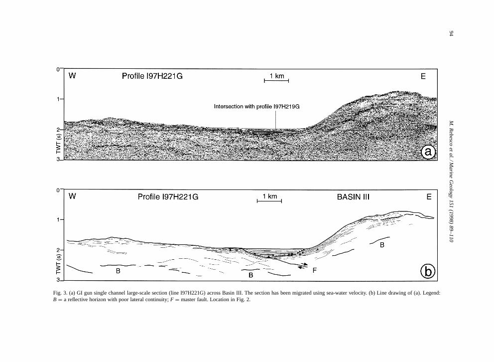
an extremely weak seafloor reflection, in places noteven detected using the Automatic Gain Control.Thickness of the unit is 98 ms twt, roughly constantin most of the basin and rapidly decreasing to zeronear the southeast side of the basin (Figs. 3 and 4).Six weak (low amplitude) reflective events with poorlateral continuity can be seen within Unit 1. Themost prominent of these is called the MBR, whichis found about 45 ms below the seafloor. A charac-teristic of the MBR is an increase in amplitude awayfrom the centre of the basin. The MBR terminatesprior to reaching the basin margins, within a chaoticseismic facies. Faulting in association with slumpingand debris flow deposits may explain the abrupt ter-mination of the MBR along the northwest flank ofBasin III and consequently the chaotic seismic char-acter of adjacent strata. Here it appears that the MBRactually climbs across a series of normal growthfaults that mark the northwest boundary of the basin.The depth to the MBR in this instance goes from 45ms in the centre of the basin to 15 ms northwest nearthe boundary faults (Fig. 4). The lateral continuity ofreflectors in Unit 1 is often interrupted by undula-tions and local onlaps. The internal reflectors (otherthan the MBR) obviously onlap the substratum re-flectors at the margin of the basin. The onlap is notalways horizontal but often curves upward.
High-reflectivity Unit 2. This unit contains six strongreflectors, showing that there are stronger impedancecontrasts than within Unit 1, that dip gently towardthe southwest, generally with increasing dips down-section on an overall divergent pattern. Lateral con-tinuity of reflectors is interrupted only at the edgesof the basin, where internal configuration becomeshummocky. In the lower portion of Unit 2 reflectorsare more commonly discontinuous throughout thebasin. Two high-amplitude reflectors are present atthe upper boundary and at some 50 ms depth withinUnit 2. Above the lower strong reflector other reflec-tions are subparallel, while below they are slightlydivergent apparently westwards, giving the unit aweakly wedging geometry. The maximum thicknessof the unit is 95 ms twt in the northwest sector of thebasin, above the depocentre overlying the deepestpart of the substratum. The reflectors within Unit 2onlap the substratum reflectors at the edge of thebasins. The onlapping reflectors are clearly horizon-
94M
.Rebesco
etal./M
arineG
eology151
(1998)89–110
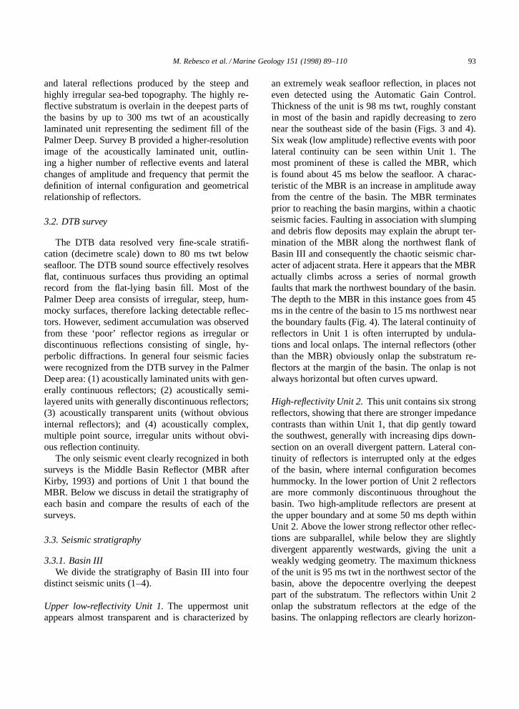
Fig. 3. (a) GI gun single channel large-scale section (line I97H221G) across Basin III. The section has been migrated using sea-water velocity. (b) Line drawing of (a). Legend:B D a reflective horizon with poor lateral continuity; F D master fault. Location in Fig. 2.
M. Rebesco et al. / Marine Geology 151 (1998) 89–110 95
Fig. 4. (a) Close-up on Basin III sediment fill from airgun single channel section I97H228. (b) Line drawing of (a). Legend: MBR DMiddle Basin Reflector; numbers 1 to 4b refer to seismic units. Location in Fig. 2.

96 M. Rebesco et al. / Marine Geology 151 (1998) 89–110
tal and abrupt along the southeast margin of the basinbut the nature of the onlap is less evident and=or dis-rupted along the northwest margin. This disruptionmay also be related to normal faulting along thenorthwest basin margin. Here there is evidence of a50 ms offset in the strong amplitude reflector pair atthe top of Unit 2 (Fig. 4). Yet unlike Unit 1, there isno suggestion of stratigraphic growth across the faultwithin Unit 2.
Lower high-reflectivity Unit 3. The unit has very lim-ited lateral extent and fills the V-shaped bottom of thebasin (Fig. 4). It contains weaker reflectors than Unit2. The unit is characterized by poor lateral continuityof reflectors and mostly hummocky internal configu-ration with weak wedge-like geometry. The reflectorsclearly onlap the substratum on the southeast side,while the northwest margin is hidden by diffractionsand=or structural complexity. The unit has a maxi-mum thickness in the depocentre of 120 ms twt.
Basin flank wedge Unit 4a. Along the southeast mar-gin of Basin III, a wedge (Unit 4a) characterizedby high-amplitude discontinuous dipping reflectorsthat downlap onto a lower unit (Unit 4b, Fig. 4)can be recognized. Some reflectors of Unit 4a ap-pear to interfinger with Units 2 and 3. Resolutionof internal reflectors is complicated by the presenceof numerous diffractions. The upper termination ofthe wedge is truncated by a sharp unconformity (seeFig. 3) onto which a semi-transparent lens (up to200 ms thick twt) draped by a stratified unit occurs.Maximum thickness is in excess of 100 ms twt.
Unit 4b. Unit 4b comprises a lens-shaped packageof reflectors limited to the southeast margin of thebasin. Clear evidence for onlap by reflectors of Unit2 and vague indication for downlap by reflectors ofUnit 4a exist along the surface boundary of Unit4b (Fig. 4). Reflectors within Unit 4b are high-amplitude, continuous, and terminate abruptly. Thereflectors are curved and have apparent westwarddips that are significantly greater than those in Units2 and 3 (above). Maximum thickness of Unit 4b isabout 45 ms twt.
Deep-Tow Boomer Units 1 and 2. The shown DTBsurvey profile in Basin III extends NE–SW and has
an acoustic penetration limited to about 60 ms twt(Fig. 5). We divide the DTB profile into upper andlower units (DTB-1 and DTB-2) with the bound-ary between the two sections corresponding to thestrong MBR. Unit DTB-1 is divided into five dis-tinct subunits and is described in the depocentrefrom top to bottom (a–e). Subunit 1a consists of anapproximately 4–6 ms twt thick acoustically trans-parent interval bounded at the top by a relativelystrong seafloor reflector. A weak internal reflectionis present in the deeper half. Subunit 1b consists of8–13 ms twt thick acoustically laminated sedimentswhere reflections are distinctly subparallel and re-solve contrasts in acoustic impedance at the decime-tre scale. This unit contains some thin, transparentlayers which thin apparently toward the southwest.Subunit DTB-1c consists of a 4–5 ms twt thickacoustically transparent interval. DTB-1d consists of3–4 ms twt of acoustically laminated sediment simi-lar to DTB-1b. Subunit DTB-1e consists of 8–14 mstwt of acoustically transparent sediment that thinstoward the margins of the basin.
The MBR occurs at 30–42 ms twt and is dis-tinctly concave-up. The highest amplitude of theMBR is apparently associated with the northeast sideof the basin. Unit DTB-2 lies below the MBR andconsists of an acoustically transparent unit near thelimits of acoustic resolution. Unit DTB-2 is at least20 ms twt thick but pinches out toward the northeast,between the MBR and a lower hummocky, discon-tinuous reflector. The base of unit DTB-2 is notresolved along the southwest end of the profile. Thelower, discontinuous reflector represents the acousticbasement of the DTB survey in Basin III.
3.3.2. Basin IIUnit 1. The sea bed in Basin II is only a few metresshallower than in Basin III. The seafloor slopes gen-tly toward the southwest in apparent continuity withthe slope of the seafloor in Basin III. An isolatedhill in the southwest corner of Basin II rises abovethe even floor of the basin to a relative height of200 m (Fig. 2, see location of Core 5). The upper,low-reflectivity Unit 1 contains five reflective eventsand is similar to Basin III as far as thickness andacoustic character are concerned thought it appearsmore transparent, continuous and regular on GI sec-tions (e.g. Fig. 6, Basin II) than on airgun sections

M.R
ebescoet
al./Marine
Geology
151(1998)
89–11097
Fig. 5. Deep Tow Boomer section across Basin III (location in Fig. 2). The vertical scale is provided by a floating 50 ms twt bar to the right. A seafloor depth in metres is providedto the left for reference. Location of core PD92-28 with scaled depth of penetration is also shown. Legend: MBR D Middle Basin Reflector; numbers 1a to 2 refer to seismic units.Location in Fig. 2.
98 M. Rebesco et al. / Marine Geology 151 (1998) 89–110
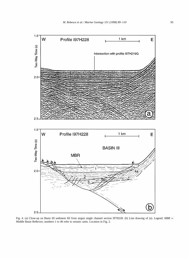
Fig. 6. (a) Close-up on Basin II sediment from GI gun single channel section I97H222G. (b) Line drawing of (a). Legend: MBR DMiddle Basin Reflector; numbers 1, 2 and 4b refer to seismic units; ‘?’ refers to the possible location of the boundary fault. Location inFig. 2.

M. Rebesco et al. / Marine Geology 151 (1998) 89–110 99
(e.g. Fig. 4, Basin III). Yet the lateral extent of theunit is much smaller because of the smaller size ofthe basin. The drape of Unit 1 over the isolated hillattains a thickness of about 90 ms twt. On the GI gunrecord there are two especially prominent reflectorswithin Unit 1 (Fig. 6). The upper one is recognizedas the MBR, extending across the entire width ofthe basin, as well as all reflectors within Unit 1. Thethickness of the part of the unit below the MBR isabout 50 ms twt.
Unit 2. Unit 2 is outlined by its upper highly reflec-tive boundary dipping slightly to the northwest. In-ternal reflectors are subhorizontal or slightly dippingtoward the northwest. Continuity of reflectors towardthe northwest margin is interrupted by a chaoticpackage (up to 150 ms twt thick) of high-amplitudediscontinuous reflectors, whose upper boundary isvery irregular, generating diffractions. This chaoticunit extends for almost 1.5 km, thinning toward thesoutheast, and is underlain by an acoustically semi-transparent interval up to 130 ms twt thick. Thelower Unit 3 and the wedge on the SE slope (Unit4a) apparently are both missing. However, a lens-shaped unit (less than 80 ms twt thick and about 1km wide) with low-amplitude, discontinuous inter-nal reflectors, similar to that described as Unit 4b inBasin III, is also observed at the base of the southeaststeep slope in Basin II (Fig. 6). This lens dips towardthe northwest and is onlapped by Unit 2 reflectors.
DTB Units 1 and 2. A DTB profile with 85 ms twtpenetration (Fig. 7) is oriented in a NE–SW direc-tion (roughly orthogonal to GI gun profile I97H222Gshown in Fig. 6) across about 2 km of Basin II. Theseafloor of the basin is not flat, but attains sev-eral metres of vertical relief in its northeast portionwhere it is rougher and displays higher reflectivity.Two units compose the sediment package. The up-per Unit DTB-1 is divided in two subunits. SubunitDTB-1a consists of 15–24 ms twt of acousticallylaminated to transparent intervals, in which reflec-tors diverge toward the northeast being subparallelto the seafloor at the top and subhorizontal at thebase of the subunit. The transparent intervals havea prominent wedge geometry with closure towardsthe centre of the basin, suggesting the presence ofslumped masses of sediments or debris flows at the
northeast side of Basin II where the unit attains 24ms twt thickness. The underlying subunit DTB-1bis a 8–15 ms twt thick interval mostly acousticallytransparent, with higher-reflectivity horizons whichare markedly concave upward and produce a thin-ning of the subunit towards the basin margin. Thelower boundary of Unit DTB-1 is the high-amplitudereflector previously recognized as the MBR.
The lowest Unit DTB-2 is acoustically transparentwith a thickness from 21 to 26 ms twt. Weak and dis-continuous internal reflectors are present towards thetop of the subunit, just below the MBR. The lowerboundary is represented by the acoustic basement ofthe section, an irregular hummocky reflector, analo-gous to the acoustic basement in Basin III, identifiedat 53–65 ms twt below the seafloor reflector. Thisreflector correlates to the lower of the two prominentreflectors in Unit 1 of the airgun survey.
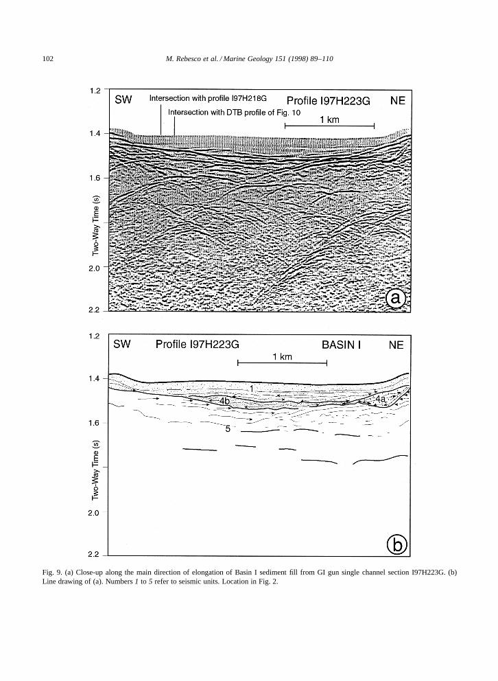
3.3.3. Basin IUnit 1. Unit 1, up to 80 ms twt thick, fills the verynarrow basin down to a highly reflective substratum(Figs. 8 and 9). The seafloor reflectivity is particularlylow and the unit is almost entirely transparent. Theseafloor has apparent and varying slope when crossedin the E–W direction, while it looks flat when crossedalong the NE–SW direction of elongation (Figs. 8 and9). The western side gains about 13 m of elevationin 500 m (¾2º), while close to the eastern wall theseafloor gains 30 m in 310 m (¾6º). The base of Unit 1is marked clearly by onlap onto an irregular erosionalsurface. This is distinctly unlike the horizontal andconformable contact between Units 1 and 2 in BasinsII and III. There is evidence for internal terminationor convergence of weak reflectors in Unit 1 from thenortheast to the southwest. In the E–W section theseafloor appears to follow the deeper substrate of thebasin along the margins. This is suggestive of a drapedrather than a ponded geometry.
Units 4a and 4b. Basin I apparently lacks seismicfacies 2 and 3, and below Unit 1 the substratum iscomposed of a series of high-amplitude, hummocky,and truncated reflections (Fig. 9). We divide thishighly reflective interval into two units that we name4a and 4b accordingly to the units of similar acousticfacies in Basin II and III. Unit 4a is characterizedby a wedge geometry along the northeast side of

100M
.Rebesco
etal./M
arineG
eology151
(1998)89–110
Fig. 7. Deep Tow Boomer section across Basin II. The vertical scale is provided by a floating 50 ms twt bar to the left. The water depth in metres is provided to the rightfor reference. Location of core PD92-5 with scaled depth of penetration is also shown. Legend: MBR D Middle Basin Reflector; numbers 1a, 1b, and 2 refer to seismic units.Location in Fig. 2.

M. Rebesco et al. / Marine Geology 151 (1998) 89–110 101
Fig. 8. (a) Close-up along the main direction of elongation of Basin I sediment fill from GI gun single channel section I97H218G. (b)Line drawing of (a). Numbers 1 and 4b refer to seismic units. Location in Fig. 2.
the basin and it contains high-amplitude internalreflections. Such reflectors are discontinuous anddip steeply toward the centre of the basin. Unit4b is confined to the bottom of the basin. It islenticular with an upper erosional contact with thelower boundary of Unit 1. Internal reflectors are ofvery high amplitude, contorted and discontinuous.Its maximum thickness is 40 ms twt.
Unit 5. Unit 5 lies below 4b and is bounded at thetop by a very high-amplitude reflector. This reflec-tor truncates subhorizontal, relatively low-amplitudeand discontinuous reflectors found within Unit 5.The base of Unit 5 is ill-defined and may correspondto the limit of acoustic resolution associated withabundant diffractions. Thickness of Unit 5 may ap-proach 200 ms. Mid-way down in Unit 5 a set ofthree linear, horizontal, high-amplitude reflectors arefound (Fig. 9). These reflectors are unique becauseall three contain sharp lateral terminations indicatinglateral changes in acoustic impedance. It is possiblethat these reflectors are the expression of a faultplane dipping out of the section and striking subpar-allel to the orientation of the section.
DTB Unit 1. The DTB seismic profile in Basin I(Fig. 10) trends north to south and displays acous-
tic penetration to at least 70 ms twt. We identifythree subunits: Units DTB-1a, -b, and -c. The up-per subunit, DTB-1a, is acoustically laminated at thescale of a few decimetres and is ¾7 ms twt thick.Reflectors are distinctly subparallel but they are nothorizontal. The middle subunit, DTB-1b, consists ofa less clearly imaged, acoustically laminated intervalapproximately 25 ms twt thick that gives the impres-sion of gradual attenuation of reflectivity with depth.Subunits 1a and 1b form a drape across the northflank of the basin. The lowest subunit, DTB-1c, is18 ms twt thick and acoustically transparent, withoccasional but discontinuous reflectors. A strongersingle, subhorizontal reflector towards the base ofthe seismic profile is the acoustic basement.
3.4. Acoustic character of the deeper units
The layered sedimentary units described aboverest on a rather homogeneous deeper seismic unitwith poor seismic characterisation. High-amplitudereflectors are common, mostly with hyperbolic pat-tern indicating diffractions from both seafloor topo-graphic features and lithological or structural dis-continuities from deeper below. A reflective horizonB with poor lateral continuity is present between 1and 1.5 s twt below the seafloor reflector below the
102 M. Rebesco et al. / Marine Geology 151 (1998) 89–110
Fig. 9. (a) Close-up along the main direction of elongation of Basin I sediment fill from GI gun single channel section I97H223G. (b)Line drawing of (a). Numbers 1 to 5 refer to seismic units. Location in Fig. 2.

M.R
ebescoet
al./Marine
Geology
151(1998)
89–110103Fig. 10. Deep Tow Boomer section across Basin I. The vertical scale is provided by a floating 50 ms twt bar to the left. The water depth in metres is provided to the right for
reference. Location of core PD92-30 with scaled depth of penetration is also shown. Numbers 1a, 1b, and 1c refer to seismic units. Location in Fig. 2.

104 M. Rebesco et al. / Marine Geology 151 (1998) 89–110
sediment fill of Basin III and its surrounding flanks(Fig. 3). The envelope of this fragmented horizonmarks the acoustic basement of the GI gun sections.Migration of the single channel data with uniformvelocity (water velocity 1500 m=s) improves thelateral continuity of horizon B which is roughly sub-parallel to the seafloor along the section displayedin Fig. 3. This horizon is much less evident acrossBasins I and II. Between horizon B and the seaflooronly hyperbolic or poorly organised reflections arepresent with the exception of an eastward-dippingreflector at the western end of Fig. 3 and a packageof coarsely laminated units at the eastern end of thesame section.
A prominent high-amplitude reflector with appar-ent dip towards the east located below the depocentreof Basin III is interpreted as the master fault (F) ofthe half-graben structure that produces active subsi-dence of the basin. Other weaker reflectors on thefootwall side of the master fault may represent a setof conjugate slip surfaces (see details in Fig. 4).
The acoustic character of the deeper units iscompatible with both (1) a thick layer of glacialsediments with chaotic geometry, in which case hori-zon B represents the basal contact of the diamictonresting on a (metamorphic) basement, and (2) ahighly tectonised metamorphic complex, dominatedby structural discontinuities, in which case horizonB is only coincidentally subparallel to the seafloor.
4. Interpretation
Here we compare the acoustic stratigraphy of theDTB profiles to those from the airgun survey anddiscuss tectonic and depositional processes that bestexplain our observations.
4.1. Acoustic velocities and depth conversion
The P-wave velocity of the upper sediments ofUnit 1 has been measured on cores and is in therange of 1400 m=s (Bissel, 1993). The acoustic lam-ination observed in subunit DTB-1a is believed to bethe result of slight contrasts in acoustic impedanceproduced by variations in biogenic silica content(Bissel, 1993). The only lithologic changes observedare between siliceous mud (SM) and hemipelagic
sediments and occur at a centimetre or decimetrescale. Given the uniformity of the acoustic characterat the airgun and GI gun resolution scale, we ex-trapolate the same lithology all the way down to thebase of Unit 1. Sediment compaction has been likelylimited by the extremely high rates of fine-grainedsediment accumulation, therefore in the estimationof Unit 1 subbottom depth in metres we preferredto consider as constant the measured sound wavevelocity of 1400 m=s, neglecting a possible slightvelocity increase below the cores. The higher reflec-tivity of the lower units suggests a sharp contrast ofacoustic impedance in terrigenous, coarser-grainedsediments, for which compaction is likely to oc-cur also at high rates of sediment accumulation. Inthe absence of direct or indirect measurement ofsound velocity, we apply corrections with a constantreference velocity of 1800 m=s from Unit 2 to 5,though the occurrence of velocity variations is notdiscounted. A scheme of the seismic–stratigraphicrelationship between the three Palmer Deep basins,on a depth scale, is presented (Fig. 11).
4.2. Basin III
The half-graben structure of Basin III is markedby growth faulting within Unit 1 but limited growthduring deposition of Units 2 and 3, the highlyreflective intervals. The upper portion of Unit 1is Holocene SM that contains alternating beds ofhemipelagic=ice-rafted debris and diatom mud tur-bidites (Kirby et al., 1998). The low amplitude ofseafloor and internal reflectors in Unit 1 indicatelow acoustic impedance contrasts compatible withthe lithology of these fine-grained, high accumu-lation rate sediments, that must retain very highporosity even at depth and do not contain strongphysical discontinuities. Sedimentation rates are es-timated to range from 0.24 to 0.13 cm=yr basedupon recovery of an 11-m-long core (Kirby et al.,1998). Such rapid rates, however, are apparentlyslow enough to allow observable growth faultingduring the Holocene along the down-thrown side ofthe boundary fault (approximately 15–20 m of dis-placement, see Fig. 4). This movement on growthfaults is consistent with intervals of turbidite gener-ation, reworking of SM, and sediment gravity flowconsistent with the overall ponded geometry of the

M.R
ebescoet
al./Marine
Geology
151(1998)
89–110105
Fig. 11. Seismic–stratigraphic scheme of units identified in Palmer Deep Basins I, II and III. All stratigraphic columns are at the same scale. All depths are in metres convertedfrom travel time using 1400 m=s reference velocity in airgun Unit 1 and all DTB units, and 1800 m=s reference velocity for deeper units. See text for details; mbf D metres belowseafloor.

106 M. Rebesco et al. / Marine Geology 151 (1998) 89–110
fill of Basin III. Such redeposition has left a ra-diocarbon profile for sediment cores that containsnumerous apparent stratigraphic inversions withinturbidite intervals (Kirby et al., 1998). The boundarybetween subunits 1a and 1b corresponds to a signif-icant change in magnetic stratigraphy as observed incore 28 (Kirby et al., 1998).
The age of the MBR is conjectural but can be asyoung as 12.5 ka to as old as 23 ka, using the rates ofdeposition derived from piston cores in Basin III (seeabove). This implies that all of Unit 1, including thenearly 40 m of section laying below the MBR, is LatePleistocene to Holocene in age. The MBR itself mustrepresent a contrast in acoustic impedance within aSM unit, perhaps due to the presence of a sand- orcarbonate-rich interval related to a sediment gravityflow. Alternatively a period of reduced sedimentationor hiatus within Unit 1 may have allowed for greatercompaction of the sediment.
The basin-fill geometry of the three seismic units(1, 2, and 3) in Basin III (as well as in BasinII) indicates that sedimentation is driven primarilyby gravity flows from the steep flanks, where nosignificant accumulation of sediment occurs, apartfrom a wedge (Unit 4a) on the eastern slope thatis apparently coeval with Units 3 and 2. Depositionof these units was most likely rapid, since there islittle evidence for movement on growth faults inthese layers (Fig. 4). There is no evidence of glacialerosional features (e.g., glacial troughs, subglacialtunnels, or diffraction of acoustic energy that istypically associated with ice grounding). Moreoverthe upward convex profile of the Unit 4a wedge andthe interfingering between Unit 4a and Units 2 and 3suggest subaqueous deposition rather than subglacialerosion. The increasing amplitude and the decreasinglateral continuity of reflectors towards the side ofthe basins in Units 1 and 2 suggest that coarsermaterial and debris flow deposits originating at thefoot of the wedge are present at the edges of thebasins, while finer, relatively turbiditic sediments arepresent towards the centre. The overall wedge-likegeometry of the lower part of Units 2 and 3 indeedsuggests a provenance of debris from the southeastslope of Basin III, which is the steepest and likelymost unstable.
A marked difference in sediment texture and com-position must exist between the upper low-reflectiv-
ity Unit 1 and the two underlying highly reflectiveUnits 2 and 3. We propose that the seismic characterof Unit 2 and its stratigraphic position are indicativeof proximal glacial marine deposits of siliciclasticcharacter, likely silt and sand interbeds. In this caseproximal is used to indicate direct sediment supplyfrom grounded ice along the boundary of the basin.A depositional analogue to Unit 2 can be found to-day along the inner basin of Brialmont Cove, a bayalong the northern Danco Coast, Antarctic Penin-sula. Here, approximately 150 m of well stratifiedsilt and subordinate sand turbidites are ponded infront of the Cayley Glacier complex (Domack, 1990;Domack and McClennen, 1996). The sedimentationrate within these deposits is on the order of a fewcm=yr, an order of magnitude greater than that ob-served for Unit 1.
There is no evidence of growth faulting along thefault plane within Units 2 and 3. Indeed, there issome evidence for drag folding of sediments at themargins of the antithetic fault, within the footwalland hanging wall. More complex reflector geome-try including discontinuity within deeper reflectors,specifically in Unit 3, may be explained by shortsegmentation along antithetic faults as illustrated inFig. 4.
4.3. Basin II
Basin II has the same general stratigraphy asBasin III except that the internal reflectors in Unit1 appear in the DTB records to be discordant withthe seafloor. In addition a well-defined boundaryfault is absent along the northwest side of the basin,probably hidden by chaotic or diffracted seismicunits suggestive of a large slump complex (Fig. 6).Sediments recovered from the side of the slumpappear to contain a condensed section of SM similarto Unit 1 (Kirby et al., 1998). This is consistentwith the observation of stratigraphic drape of theupper part of Unit 1 over the slump as seen in theairgun survey (Fig. 6). The slump complex musttherefore pre-date the MBR. In the lower portionof Unit 2 we see an angular truncation of reflectorsthat we interpret as an indication of tilting of theold layers along the boundary fault prior to the endof Unit 2 deposition. The geometry of Unit 4b ismost compatible with a deformed sediment package

M. Rebesco et al. / Marine Geology 151 (1998) 89–110 107
slumped from the southeast side of the basin at thefoot of a sediment wedge. However, we do not haveseismic evidence to support this.
4.4. Basin I
In Basin I, Unit 1 does not have a typical ponded(basin fill) geometry and can be considered as adrape of acoustically laminated sediments over atilted substratum (Fig. 10). The exceptionally lowreflectivity of the unit in Basin I is compatible withprimarily hemipelagic and high accumulation ratedeposition with only occasional turbidite deposition.Cores of the upper 10 m of sediment (Leventer etal., 1996) provide much less evidence of turbiditedeposition than in the other two basins and supporta hemipelagic to pelagic origin. Well laminated SMwithin Basin I is accumulating at the rate of 0.3 to0.4 cm=yr (Leventer et al., 1996) suggesting an ageof 19 to 14 ka BP for the base of Unit 1, which isstratigraphically equivalent to the inferred age of theMBR observed in Basins III and II.
The contorted, highly reflective units at the bot-tom of Basin I (tentatively identified as Units 4–5)are probably composed of coarse-grained debritesand turbidites that include high-density glacigenicterrigenous sediments, able to provide a very highacoustic impedance contrast with the overlying low-reflectivity unit.
5. Inferred history of basin infill
The Palmer Deep region occupies a key positionwith regard to shelf-wide glacial advance across thecontinental shelf edge, some 120 km northwest ofPalmer Deep. The work of Pudsey et al. (1994) andRebesco et al. (1998) indicates that the head of amajor ice drainage system lies within the PalmerDeep. Here coastal glaciers draining off the Penin-sula plateau (via fjord basins) and the Anvers Islandice cap converged in the past and led to constricteddrainage across the shelf and deposition of a largewedge of prograded glacigenic sediment at the edgeof the shelf. The last recession of grounded icefrom the outer shelf is believed to have taken placeat around 11,000 radiocarbon years BP, correlativewith recession from Last Glacial Maximum (LGM)
conditions in the Northern Hemisphere (Pudsey etal., 1994).
The stratigraphic sequence we describe from thePalmer Deep basins is inconsistent with full glacialconditions within Basins III and II during the LGM.Most of the undisturbed basin fill in the deepestportions of the Palmer Deep (Basins III and II)clearly pre-dates the LGM because the MBR is ofLate Pleistocene age. In contrast, we suggest thatBasin I was indeed fully glaciated during the LGM.
In Basin I the absence of the layered Units 2 and3 and the occurrence of deformation and erosionaltruncation of glacial marine sediments of Units 4and 5 may indicate ice grounding during the lastglaciation, and postglacial deposition of the siliceousoozes of Unit 1 on top of the deformed sequenceduring the Holocene, consistent with the 14–19 kaage estimate for the base of Unit 1.
Deposition of Units 2 and 3 in the deeper BasinsIII and II is more difficult to explain if the ice sheetwas indeed grounded across the entire shelf at theLGM.
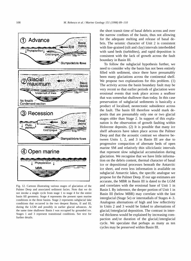
We must consider Unit 2 as the product of sub-glacial deposition within an ice-free cavity beneaththe ice sheet, similar to present-day subglacial lakesobserved beneath the East Antarctic ice sheet (Os-wald and Robin, 1973; Shoemaker, 1991; Kapista etal., 1996). Maintenance of ice-free conditions withinthe subglacial basins would be provided by the nar-rowness and extreme depth (>1400 m) of the basins,which prevent ice deformation and complete ground-ing if ice flow and thickness are not appropriate.Basin I, however, was filled by ice because it isperched about 400 m higher. In the framework ofthis model (Fig. 12) subaqueous deposition beneaththe ice sheet is dominated by fine-grained sedimen-tation derived from both fallout of undermelt ofbasal debris and lateral gravity flows from the in-flow of meltwater along the periphery of the basin.While it is difficult to find appropriate analogues forthe proposed undermelt of basal debris, there aremany examples of glacial gravity-flow processes inthe Northern Hemisphere margins (e.g. Bear Island,Laberg and Vorren, 1995; and Baffin Island, Straversand Powell, 1997). The absence of very large clasts(i.e. boulder size) in Unit 2, suggested by the lackof diffractions otherwise common in the seismic dataof proximal glacio-marine sediments, is favoured by
108 M. Rebesco et al. / Marine Geology 151 (1998) 89–110
Fig. 12. Cartoon illustrating various stages of glaciation of thePalmer Deep and associated sediment facies. Note that we donot invoke a single cycle from stage 1 to stage 4 for the entirebasin fill geometry. Stage 4 represents the present open marineconditions in the three basins. Stage 2 represents subglacial lakeconditions that occurred in the two deepest Basins, II and III,during the LGM and possibly in earlier glacial advances. Atthe same time shallower Basin I was occupied by grounded ice.Stages 1 and 3 represent transitional conditions. See text forfurther details.
the short transit time of basal debris across and overthe narrow confines of the basin, thus not allowingfor the adequate melting and release of basal de-bris. The seismic character of Unit 2 is consistentwith fine-grained (silt and clay) intervals interbeddedwith sand beds (turbidites), and rapid deposition isconsistent with the lack of growth across the faultboundary in Basin III.
To follow the subglacial hypothesis further, weneed to consider why the basin has not been entirelyfilled with sediment, since there have presumablybeen many glaciations across the continental shelf.We propose two explanations for this problem. (1)The activity across the basin boundary fault may bevery recent so that earlier periods of glaciation wereerosional events that took place across a seafloorthat was somewhat shallower than today. In this casepreservation of subglacial sediments is basically aproduct of localised, neotectonic subsidence acrossthe fault. The basin fill therefore would mark de-posits that are presumably only one or two glacialstages older than Stage 2. In support of this expla-nation is the observation of growth faulting withinHolocene deposits. (2) It is possible that many iceshelf advances have taken place across the PalmerDeep and that the acoustic contrast we observe be-tween Units 1, 2, and 3 in Basin III are due toprogressive compaction of alternate beds of openmarine SM and relatively thin siliciclastic intervalsthat represent slow subglacial accumulation duringglaciation. We recognise that we have little informa-tion on the debris content, thermal character of basalice or depositional processes beneath the Antarcticice sheet, and even less information is available onsubglacial Antarctic lakes, the specific analogue wepropose for the Palmer Deep. If our age estimates areaccurate, the MBR in Basin III is dated to the LGMand correlates with the erosional base of Unit 1 inBasin I. By inference, the deeper portion of Unit 1 inBasin III (below MBR) may correlate with the lastinterglacial (Stage 5e) or interstadials of Stages 4–3.Analogous alternations of high and low reflectivityin Units 2 and 3 would be linked to alternations ofglacial=interglacial deposition. The contrast in inter-val thickness would be explained by increasing com-paction and=or duration of the glacial=interglacialcycle. We speculate that perhaps as many as tencycles may be preserved within Basin III.

M. Rebesco et al. / Marine Geology 151 (1998) 89–110 109
Unit 4a, well developed on the eastern flank ofBasin III, is interpreted, in analogy to the glacioma-rine facies architecture of the western Spitsbergencontinental margin (Boulton, 1990), to represent awedge likely related to the deposition in a proglacialenvironment formed during the ice sheet advanceover the basin (Fig. 12). The sharp unconformity thatcuts the upper termination of this wedge could be in-dicative of subglacial erosion, whereas the semitrans-parent lens above this unconformity could representa till. The uppermost draping unit, above the semi-transparent lens, is probably indicative of postglacialdeposition. The wedge of Unit 4a downlaps onto themound-shaped Unit 4b that probably represents anearly stage of the basin fill in all three basins. There-fore, we believe that the contorted highly reflectiveunits at the base of Basins III, II, and I (Units 4b–5)are probably composed of coarse-grained debritesand turbidites that include high-density glacigenicterrigenous sediments, deposited near the bottom ofthe basin.
We believe that the formation of the proglacialwedge in Basin III can be related to an early stageof ice sheet advance, when the ice-grounding linereaches the edge of a slope, where there is enoughaccommodation space to release sediments. If theslope is not too steep (Basin III), sediments canbe progressively stacked prograding foresets. If theslope is too steep (Basins II and I), sediment tends toby-pass the slope and reach the bottom of the basin(Unit 4b). Another necessary condition for formationof a wedge on the flank of Basin III is also that itwas larger than Basins II and I. This means that thetransit time of the ice sheet during its advance overthe basin margins was longer than in Basins II and I,and was probably long enough to allow melting andrelease of sediments from the ice base.
6. Conclusions
(1) The Palmer Deep is a fault-bounded exten-sional basin in which activity of faults is evidencedby stratigraphic offset within Holocene sections.
(2) The Palmer Deep contains a very thick sedi-ment infill up to about 270 m that is arranged in acomplex internal seismic stratigraphy.
(3) Comparative use of DTB and airgun sources
reveals a complementary resolution of both deep andshallow (decimetre scale) stratigraphy.
(4) The shallow Middle Basin Reflector, corre-lated between both surveys, is most likely of latestPleistocene age and therefore about 80% of the basinfill pre-dates the classic LGM.
(5) The two deepest Basins III and II were notfilled by grounded ice during the LGM and weretherefore subglacial lakes. Grounding of ice duringthe LGM has occurred only in the shallower Basin I.
(6) The Palmer Deep has acted as a natural sed-iment trap for glacial=interglacial sedimentation. In-terglacial sedimentation is by high accumulation ratesiliceous ooze. Glacial sedimentation is by fallout offine-grained sediments from the basal ice and gravityflows on the basin flanks.
Acknowledgements
This work was supported by the National Sci-ence Foundation (Office of Polar Programs–OceanSciences) through the Research in UndergraduateInstitutions program (OPP 89-15977) and by ‘Pro-gramma Nazionale Ricerche in Antartide’ (PNRAExpedition 1996–97). We thank the crews of the RVPolar Duke and RV OGS-Explora, and the staff ofAntarctic Support Associates and the technical staffof OGS for their enthusiastic assistance for the fieldprogram. C. Pelos and L. Sormani contributed withshipboard processing of OGS seismic data. Con-structive reviews by P.F. Barker, C.J. Pudsey, T.C.E.van Weering and D.G. Masson are warmly acknowl-edged. Support of the PEW charitable trust is alsoappreciated.
References
Bissel, D.M., 1993. Synthetic Seismogram Generation: A Studyin the Antarctic Peninsula Region. B.A. Thesis, MiddleburyCollege, Middlebury, VT, 52.
Boulton, G.S., 1990. Sedimentary and sea level changes duringglacial cycles and their control on glacimarine facies architec-ture. In: Dowdeswell, J.A., Scours, J.D. (Eds.), GlacimarineEnvironments: Processes and Sediments. Geol. Soc. LondonSpec. Publ. 53, 15–52.
Domack, E.W., 1990. Laminated terrigenous sediments from theAntarctic Peninsula: the role of subglacial and marine pro-

110 M. Rebesco et al. / Marine Geology 151 (1998) 89–110
cesses. In: Dowdeswell, J.A., Scourse, J.D., (Eds.) Glacima-rine Environments; Processes and Sediments. Geol. Soc. Lon-don Spec. Publ. 53, 91–103.
Domack, E.W., McClennen, C.E., 1996. Accumulation of glacialmarine sediments in fjords of the Antarctic Peninsula andtheir use as Late Holocene paleo environmental indicators.In: Ross, R., Hoffman, E., Quetin, L. (Eds.) Foundations forEcosystem Research West of the Antarctic Peninsula. Am.Geophys. Union, Antarct. Res. Ser.
Hawkes, D.D., 1981. Tectonic segmentation of the northernAntarctic Peninsula. Geology 9, 220–224.
Herron, E.M., Tucholke, B.E., 1976. Sea-floor magnetic patternsand basement structure in the southwestern Pacific. Init. Rept.DSDP 35, 263–278.
Kapista, A.P., Ridley, J.K., de, Q., Robin, G., Siegert, M.J.,Zotikov, I.A., 1996. A large deep freshwater lake beneath theice of central East Antarctica. Nature 381, 684–686.
Kim, Y., Kim, H.-S., Larter, R.D., Camerlenghi, A., Gamboa,L.A.P., Rudowski, S., 1995. Tectonic deformation in the uppercrust and sediments at the South Shetland Trench. In: Cooper,A.K., Barker, P.F., Brancolini, G. (Eds.), Geology and SeismicStratigraphy of the Antarctic Margin. Am. Geophys. Union,Antarct. Res. Ser. 68, 157–166.
Kirby, M.E., 1993. High Resolution Seismic Stratigraphy andSedimentology of Holocene Glacial Marine Deposits in thePalmer Deep, Bellingshausen Sea, Antarctica. B.A. Thesis,Hamilton College, Clinton, NY, 60.
Kirby, M.E., Domack, E.W., McClennen, C.E., 1998. Fine-scalestratigraphy and sedimentology of Holocene glacial marinedeposits in the Palmer Deep, Bellingshausen Sea, Antarctica.Mar. Geol. (in press).
Laberg, J.S., Vorren, T.O., 1995. Late Weichselian submarinedebris flow deposits on the Bear Island trough mouth fan. Mar.Geol. 127, 45–72.
Larter, R.D., Barker, P.F., 1991. Effects of ridge crest–trench in-teraction on Antarctic–Phoenix Spreading: forces on a youngsubducting plate. J. Geophys. Res. 96, 19583–19607.
Larter, R.D., Rebesco, M., Vanneste, L.E., Gamboa, L.A.P.,Barker, P.F., 1997. Cenozoic tectonic, sedimentary and glacialhistory of the continental shelf west of Graham Land, Antarc-tic Peninsula. In: Cooper, A.K., Barker, P.F. (Eds.), Geologyand Seismic Stratigraphy of the Antartcic Margin, Part 2. Am.Geophys. Union, Antarct. Res. Ser. 71, 1–27.
Leventer, A., Domack, E.W., Ishman, S.E., Brachfeld, S., Mc-Clennen, C.E., Manley, P., 1996. Productivity cycles of 200–300 years in the Antarctic Peninsula region: understandinglinkages between the sun, atmosphere, oceans, sea ice andbiota. Geol. Soc. Am., Bull. 108, 1626–1644.
Oswald, G.K.A., Robin, G. de Q., 1973. Lakes beneath theAntarctic ice sheet. Nature, 245, 251–254.
Pudsey, C.J., Barker, P.F., Larter, R.D., Ice sheet retreat from theAntarctic Peninsula shelf. Continental Shelf Res. 14: 1647–1675, 1994.
Rebesco, M., Camerlenghi, A., Zanolla, C., 1998. Bathymetryand morphogenesis of the continental margin west of theAntarctic Peninsula. Terra Antart. (in press).
Shoemaker, E.M., 1991. On the formation of large subglaciallakes. Can. J. Earth Sci. 28, 1975–1981.
Stravers, J.A., Powell, R.D., 1997. Glacial debris flow depositson the Baffin Island shelf: seismic facies architecture of till-tongue-like deposits. Mar. Geol. 143, 151–168.