seismic stabilization of historic adobe structures - the getty · seismic stabilization of historic...
TRANSCRIPT

The Getty Conservation Institute
Seismic Stabilization ofHistoric Adobe Structures Final Report of the Getty Seismic Adobe Project
E. Leroy Tolles
Edna E. Kimbro
Frederick A. Webster
William S. Ginell
GC
I Scie
ntific P
rogra
m R
ep
orts

GCI Scientific Program Reports
Seismic Stabilization ofHistoric Adobe StructuresFinal Report of the Getty Seismic Adobe Project
E. Leroy Tolles
Edna E. Kimbro
Frederick A. Webster
William S. Ginell
The Getty Conservation Institute Los Angeles

Seismic Stabilization ofHistoric Adobe StructuresFinal Report of the Getty Seismic Adobe Project

Dinah Berland, Editorial project manager
Dianne Woo, Manuscript editor
Anita Keys, Production coordinator
Garland Kirkpatrick, Cover designer
Hespenheide Design, Designer
© 2000 The J. Paul Getty Trust
All rights reserved.
Illustrations of models in chapter 7 courtesy of IZIIS, University “SS. Cyril and
Methodius,” Skopje, Republic of Macedonia.
Printed in the United States of America
10 9 8 7 6 5 4 3 2 1
The Getty Conservation Institute works internationally to advance conservation
in the visual arts. The Institute serves the conservation community through sci-
entific research, education and training, model field projects, and the dissemina-
tion of information. The Institute is a program of the J. Paul Getty Trust, an
international cultural and philanthropic institution devoted to the visual arts
and the humanities.
The GCI Scientific Program Reports series presents current research being con-
ducted under the auspices of the Getty Conservation Institute.
Library of Congress Cataloging-in-Publication Data
Seismic stabilization of historic adobe structures : final report of the Getty Seismic
Adobe Project / E. Leroy Tolles . . . [et al.].
p. cm.—(GCI scientific program reports)
Includes bibliographical references.
ISBN 0-89236-587-0
1. Building, Adobe. 2. Buildings—Earthquake effects. 3. Earthquake engineer-
ing. 4. Historic Buildings—Southwest (U.S.)—Protection. I. Tolles, E. Leroy,
1954– II. Getty Adobe Project. III. Getty Conservation Institute.
IV. Series.
TH4818.A3 S45 2000
6939.22—dc21 00-022015
CIP
Contents
ix Foreword Timothy P. Whalen
xi Preface William S. Ginell
xv Acknowledgments
xvii Project Participants
Chapter 1 1 Background to the Getty Seismic Adobe Project
1 Getty Seismic Adobe Project Goals and Purpose
2 Life-Safety Issues for the Seismic Retrofit of Adobe Buildings
2 Conservation Issues for the Seismic Retrofit of Adobe Buildings
4 Seismic Performance and Seismic Retrofit
8 Project Approach
First-year activities
Second-year activities
Third-year activities
Chapter 2 11 Overview and Procedures for Models 1–9
11 Seismic Retrofit Techniques
13 Overview of Tests
14 Description of Materials and Models
Adobe material
Model design and construction
Retrofit measures
Model similitude
17 Description of Test Procedure
Test setup
Instrumentation
Simulated earthquake motions
Documentation
Chapter 3 21 Description of Tests for Models 4–6
21 Description of Models
Model 4 (SL 5 5)
Model 5 (SL 5 11)
Model 6 (SL 5 11)
23 Test Results for Model 4
28 Test Results for Model 5
31 Test Results for Model 6
37 Summary of Test Results for Models 4–6

Chapter 4 41 Description of Tests for Model 7
41 Layout of Model 7
42 Retrofit Measures
45 Summary of Test Results for Model 7
Chapter 5 53 Description of Tests for Models 8 and 9
53 Layout of Models 8 and 9
55 Model 8 Retrofit Measures
58 Test Results for Model 8
58 Flexural Test of a Wall Element with Center-Core Reinforcement
59 Test Results for Model 9
70 Summary of Test Results for Models 8 and 9
Chapter 6 73 Analysis of Test Results for Models 1–9
73 Analysis of Model Test Results
Initial crack development (test levels II–IV)
Performance during moderate to strong seismic levels (test levels V–VII)
Performance during very strong seismic levels (test levels VIII–X)
Summary of performance of model buildings
86 Summary of Field Observations after the Northridge Earthquake
87 Comparison of Laboratory Results and Field Observations
Chapter 7 89 Description of Tests for Models 10 and 11
91 Overview of Tests
92 Materials Tests
92 Dynamic Testing Procedures
93 Model Buildings
Chapter 8 103 Test Results and Data Analysis for Models 10 and 11
104 Model 10—Unretrofitted
Elastic response
Damage progression
Performance and collapse during severe ground motions
111 Model 11—Retrofitted
Elastic response
Damage progression
Performance during severe ground motions
119 Loads on Elements of the Retrofit System
Analysis and discussion of results
Comparison of elastic response
Comparison of damage progression
Comparison of performance during severe ground motions
134 Performance Observations and Summaries
138 Summary of Comparison of Performance of Small- and Large-Scale Models
Chapter 9 141 Recent Application of GSAP Technology

Chapter 10 145 Summary and Conclusions
146 Assessment of Retrofit Measures
147 Relative Model Performance
Chapter 11 149 Suggestions for Future Research
151 References
153 Glossary
155 Bibliography of Publications Resulting from GSAP
157 About the Authors

There is something satisfying and appealing about the use of earth asa building material. An earthen building draws its raw material fromthe ground on which it stands and eventually returns to the earth—the ultimate recyclable and renewable resource. Probably the first ofhumankind’s building materials, earth has been in continuous use in vari-ous guises throughout history and on every continent. Of the many dis-tinct ways in which earth has been used to construct human habitations,adobe may be the simplest. The word adobe comes from the Arabic wordfor “brick” and was introduced to the Americas, along with adobe tech-nology itself, by the Spanish. Mud brick was widely adopted in theSouthwest as a building material: the simplicity of the technology andperhaps absence of timber or kilns as well as the region’s bright sunshineand dry desert air were highly conducive to its use.
As is commonly known, however, adobe structures are highlyvulnerable to earthquakes. Categorized by architects and builders asunreinforced masonry, and the weakest type of structure in that category,adobe buildings have been devastated in areas of high seismicity. Aspointed out in this book, of the approximately 900 adobes originally con-structed in the San Francisco Bay Area alone, the number had dwindledto about 65 by the 1940s. Today only some 350 historic adobes remainin California, many of which date to the Spanish colonial period.
The Getty Conservation Institute has, since its inception,addressed the threats of seismic destruction of cultural property. This isnot simply because Los Angeles itself is in a seismic zone but ratherbecause many seismic areas in the world—the west coast of North andSouth America, areas of the Mediterranean, and China, to name but afew—contain enormous concentrations of cultural patrimony. Amongthe first books published by the GCI was Between Two Earthquakes:Cultural Properties in Seismic Zones by Sir Bernard Feilden (1987). TheGCI has conducted research on securing museum objects, ranging fromextremely simple tie-down devices to highly sophisticated engineeringmounts, and has sponsored seminars and conferences, as in Quito andCairo, on earthquake response. The present book represents a furtherstep in our commitment to the issue and is the fruit of a major researchproject of the GCI.
The Getty Seismic Adobe Project (GSAP) initiative was firstdiscussed at the Sixth International Conference on Earthen Architecture,
Foreword

“Adobe 90,” held in October 1990 in Las Cruces, New Mexico, wherethe GCI and the Museum of New Mexico State Monuments had beenconducting long-term research and field testing at the historic monumentof Fort Selden, an adobe frontier fort dating from the mid-nineteenth cen-tury. The 1989 Loma Prieta earthquake in California, which had severelydamaged or destroyed historic adobe buildings in the area, was fresh inthe minds of delegates, as it emphasized once again how each significantearthquake destroys or degrades the authenticity of historic structures.
Because the earthquake codes for seismic stability inCalifornia and elsewhere require invasive retrofitting to stabilize historicstructures—which in the case of adobe results in a severe mismatch offabric—the primary objective of the GSAP initiative was to find techno-logically sympathetic and minimally invasive methods of stabilizing thesestructures. The objective was not to make adobes “earthquake-proof”but rather to ensure safety by preventing the overturning of walls duringa seismic event. As a result of ten years of research conducted with thehelp of an international group of specialists and earthquake engineers,this objective has been met. The research was conducted first on small-scale models at Stanford University and later on larger-scale models inSkopje in the Republic of Macedonia and truly represents an exemplar ofcollaborative enterprise. The first applications of GSAP research are nowtaking place in California, reflecting the ultimate purpose of conservationresearch as a whole: to identify the problem, research its solutions, anddisseminate the results—thus ensuring, insofar as possible, the applica-tion of tested methods in the field.
It is particularly gratifying for me to present this importantpublication, which is applicable not only to preservationists, engineers,and architects but also to a wider community of private owners ofearthen buildings both in the Americas and elsewhere in the world.
Timothy P. Whalen Director, The Getty Conservation Institute
x Foreword

Preface
Many of the early structures that date back to the Spanish colonialperiod in the southwestern United States were built of mud brick, oradobe. The materials for construction of the early churches, missions,and houses were generally limited to those that were available in theregion and easily worked by local artisans. Adobe has many favorablecharacteristics for construction in arid regions: it provides effective ther-mal insulation, the clayey soil from which adobe bricks are made isubiquitous, the skill and experience required for building adobe struc-tures is minimal, and building construction does not require the use ofscarce fuel. As a consequence of their age, design, and functions, surviv-ing adobe buildings are among the most historically and culturallysignificant structures in their communities.
The seismic vulnerability of California’s adobe architecturalheritage—its missions, presidios, and residential structures—has beenrecorded in mission documents since the eighteenth century. Some of theexisting adobe mission churches have been reconstructed many times onthe same site following the destruction of the preceding structure by anearthquake. For example, the 1971 San Fernando earthquake in LosAngeles County destroyed the San Fernando Mission church and severelydamaged its elegant convento (priest’s residence), the largest and mostelaborately decorated residential adobe structure ever erected inCalifornia. The Native American neophyte mural paintings of the con-vento were lost forever.
In recent years, considerable progress has been made towardunderstanding the behavior of buildings during earthquakes. Unreinforcedmasonry buildings are widely recognized as being particularly vulnerable.California law now mandates that within this decade, local jurisdictionsreduce the hazard posed by existing buildings, especially those constructedof unreinforced masonry. Adobe structures fall within the class of unrein-forced masonry buildings and are particularly susceptible to earthquakedamage. Many unreinforced masonry buildings either are being retrofittedto improve stability and to decrease the possibility of loss of life, or arebeing demolished.
The retrofitting of the vast majority of commercial and resi-dential buildings poses only economic and technical problems, and con-ventional engineering approaches are well suited to such buildings. Whenplanning reduction of the seismic vulnerability of historic and culturally

significant buildings, however, ethical considerations that limit the designalternatives must be made. Engineering interventions to improve a struc-ture’s seismic safety can lead to irreparable loss or damage to the historicfabric of the building and to its architectural or decorative features.
Many previously damaged, culturally significant, and vulner-able adobe structures are in need of structural modification that willimprove their likelihood of survival. The difficulties in implementingthese modifications lie in the often conflicting requirements of using con-ventional engineering practices while maintaining, intact, the historicaland cultural features.
When confronted by the necessity of action in face of theseismic threat, authorities responsible for the California missions andother historic adobe buildings and earthen architectural monuments areforced to choose from among four courses of action for these structures:
1. closing and fencing off the buildings, thereby beginningthe inevitable progressive deterioration caused by lack ofuse and maintenance;
2. demolishing the buildings, as has been done to many his-toric structures that fail to comply with earthquake safetyordinances;
3. retrofitting them using the presently available, highlydestructive, invasive, and expensive measures sanctionedfor adobe structures; or
4. retrofitting them using innovative, tested techniquesspecifically developed for adobe structures and designedto observe the conservation principle of minimalintervention.
The fourth course of action is the only alternative that will preserve thecultural and historic value of adobes while providing life safety to theoccupants of the buildings.
In keeping with the ongoing commitment of the GettyConservation Institute to the preservation of our collective cultural her-itage, the Getty Seismic Adobe Project (GSAP) was initiated in November1990. The goal of the project was to develop technical procedures forimproving the seismic performance of historic adobe structures consistentwith providing life safety and maintaining architectural, historic, and cul-tural conservation values.
Overview of This Book
This book is not only the final report of GSAP activities, it is also the firstpublication to provide an overview of the results of scale-model labora-tory research along with field data from a survey of damage to historicadobe buildings after an actual earthquake.
The principal part of this book contains a summary of thesmall- and large-scale shaking-table tests and an analysis of results.
xii Preface

These results are considered in relation to field observations of seismicdamage to adobes, particularly as detailed in Survey of Damage toHistoric Adobe Buildings after the January 1994 Northridge Earthquake(Tolles et al. 1996). The text summarizes the results of preliminary stud-ies that were described in internal project reports (Thiel et al. 1991;Tolles et al. 1993) and also provides details of recent experimental workthat validated an innovative approach to the problem of the seismicretrofitting of adobe structures.
Chapter 1 provides an overview of the Getty Seismic AdobeProject, its research goals, project approach, and activities. Chapter 2summarizes the small-scale-model (1:5) testing program and proceduresused at the shaking table at the John A. Blume Earthquake EngineeringCenter at Stanford University in Palo Alto, California. The results of thetests on models 4–6 are presented in chapter 3; the results for model 7are given in chapter 4; and the data on models 8 and 9 are presented inchapter 5. Chapter 6 contains an analysis and a synthesis of the signifi-cant aspects of the behavior of models 1–9.
In chapter 7, the need for large-scale-model (1:2) tests isdiscussed, along with the procedures and results obtained on the large-scale models 10 and 11. These tests were performed at the Institute ofEarthquake Engineering and Engineering Seismology (IZIIS), University“SS. Cyril and Methodius,” in Skopje, Republic of Macedonia. An analy-sis of the results of the large-scale tests is given in chapter 8. Chapter 9briefly describes one recent application of GSAP technology to theretrofitting of adobe structures in California. The conclusions reachedin this study and suggestions for future work are provided in chapter 10.At the end of the book are a glossary of terms related to adobe structuresand seismic retrofitting, and a selected bibliography of journal articles,reports, and other publications generated as a result of GSAP research.
A forthcoming volume, Planning and Engineering Guidelinesfor the Seismic Stabilization of Historic Adobe Structures by Tolles,Kimbro, and Ginell, will provide information on how to plan for andaccess further information on the retrofitting of historic adobe buildings.
William S. Ginell
Preface xiii

The authors would like to thank the many colleagues who contributed tothe successful completion of this research program. First, they would liketo thank Charles C. Thiel Jr. for his sound professional guidance duringthe first few years of this research program. His contributions were criti-cal to the design and development of the concepts of the program andthe implementation of the small-scale model tests.
They also wish to thank Helmut Krawinkler and AnneKiremidjian, who, during the course of this project, held positions asdirectors at the John A. Blume Earthquake Engineering Center, StanfordUniversity. Their support and contributions are greatly appreciated.Krawinkler was also a member of the GSAP Advisory Committee, and hiscontributions in that capacity are also very much appreciated.
Also at Stanford University, Chris Thomas was responsiblefor the construction of the nine small-scale model buildings that weretested during the research program. His hard work and attention todetail were extremely valuable to those of us who designed the tests thatdestroyed his beautiful models.
The large-scale models were built and tested under thesupervision of Predrag Gavrilovic at IZIIS, University “SS. Cyril andMethodius,” in Skopje, Republic of Macedonia. He was assisted byVeronika Sendova, Ljubomir Taskov, Lidija Krstevska, and the competentstaff of engineers and technicians at IZIIS. The authors are indebted to allof them for their contributions to the success of the final stages of GSAP.
The members of the GSAP Advisory Committee (listed onpage xviii) also played a very important role in the research process.Their valuable contributions to the project and its research goals havehelped the results to become more applicable to ongoing retrofit efforts.
The authors are particularly grateful for the support at theGetty Conservation Institute of Neville Agnew, principal project special-ist and the initial project director for GSAP; and Frank Preusser, formerhead of the GCI Scientific Program, for their strong and continued sup-port throughout this entire research project. Their interest and encour-agement were critical to the success of GSAP.
Thanks to Getty Conservation Institute staff members FordMonell, whose excellent work in assembling the original manuscript ismuch appreciated; Jacki Redeker, who organized the many electronicimages; and Valerie Greathouse, who provided bibliographic reference
Acknowledgments

assistance. Appreciation is also extended to the staff of Getty TrustPublication Services who helped bring this book to light, particularlyDinah Berland, editorial project manager for the book, and Anita Keys,production coordinator; and to consultants Dianne Woo, who editedthe manuscript, and Scott Patrick Wagner, who edited the referencesand prepared the manuscript for production.
xvi Acknowledgments

The following individuals actively participated in the Getty SeismicAdobe Project during various periods from 1990 through 1999.
Neville Agnew Principal project specialistGetty Conservation Institute, Los Angeles
Anthony Crosby Historical architectFormerly with the National Park Service, Denver
Predrag Gavrilovic Professor, civil engineeringIZIIS, University “SS. Cyril and Methodius” Skopje, Republic of Macedonia
William S. Ginell Senior scientistGetty Conservation Institute, Los Angeles
Edna E. Kimbro Architectural conservator and historianWatsonville, Calif.
Helmut Krawinkler Professor, structural engineeringStanford University, Palo Alto, Calif.
Lidija Krstevska Civil engineerInstitute of Earthquake Engineeringand Engineering Seismology (IZIIS),University “SS. Cyril and Methodius”Skopje, Republic of Macedonia
Veronika Sendova Assistant professor, civil engineeringIZIIS, University “SS. Cyril and Methodius”Skopje, Republic of Macedonia
Ljubomir Taskov Associate professor, civil engineering IZIIS, University “SS. Cyril and Methodius”Skopje, Republic of Macedonia
Charles C. Thiel Jr. Seismic structural engineerPiedmont, Calif.
Chris Thomas Engineering laboratory assistantStanford University, Palo Alto, Calif.
Project Participants

E. Leroy Tolles Seismic structural engineerEarthen Buildings TechnologiesLafayette, Calif.
Frederick A. Webster Civil/structural engineerMenlo Park, Calif.
GSAP Advisory Committee
Edward Crocker New Mexico Community FoundationSanta Fe, N.Mex.
Anthony Crosby Historical architectFormerly with the National Park Service, Denver
M. Wayne Donaldson Historical architectSan Diego, Calif.
Melvyn Green Structural engineerManhattan Beach, Calif.
James Jackson ArchitectCalifornia Department of Parks and RecreationSacramento, Calif.
Helmut Krawinkler Professor, structural engineeringStanford University, Palo Alto, Calif.
John Loomis Architect Newport Beach, Calif.
Nicholas Magalousis Former curator, Mission San Juan CapistranoLaguna Beach, Calif.
Julio Vargas Neumann Professor, structural engineering Pontifica Universidad Católica del Peru, Lima
xviii Project Participants

Getty Seismic Adobe Project Goals and Purpose
The Getty Seismic Adobe Project (GSAP) was initiated by the GettyConservation Institute in November 1990 for the purpose of developingtechnical procedures for improving the seismic performance of historicadobe structures with minimal impact on the historic fabric of thesebuildings. The program focused on the Spanish colonial missions and his-toric adobes in seismic areas of the southwestern region of the UnitedStates, with expected applications to historic adobes in other seismicregions, particularly Central and South America.
Many historic adobe buildings have fared very poorly duringearthquakes. The seismic behavior of adobe buildings—as well as thosemade of stone and other types of unreinforced masonry—is commonlycharacterized by sudden and dramatic failure. A high likelihood of seri-ous injuries and loss of life usually accompanies the local or generalcollapse of such structures. Generally, the evaluation of the engineeringcommunity is that adobe buildings, as a class, pose the highest riskamong the various building types. Nevertheless, it has been observedthat some adobes have withstood repeated, severe earthquake groundmotions without total collapse.
The seismic upgrading of historic buildings embraces two dis-tinct goals: (1) seismic retrofitting to provide adequate life-safety protec-tion, and (2) preserving the historic (architectural) fabric of the building.These goals are often perceived as fundamentally opposed. In currentseismic retrofitting practices, substantial alterations of structures are usu-ally required, involving new structural systems and often substantialremoval and replacement of building materials. Historic structures thatare strengthened and fundamentally altered in this manner lose much oftheir authenticity. They are often virtually destroyed because of their pre-sumed earthquake risk without, or instead of, waiting for an earthquaketo damage them. As a result, the conflict is seen as an either/or proposi-tion: either the building can be retrofitted, making it safe during seismicevents but destroying much of the historic fabric in the retrofittingprocess, or the building with its historic fabric can be left intact whilethe risk of potential structural failure and collapse during future seismicevents is accepted.
Chapter 1
Background to the Getty Seismic Adobe Project

2 Chapter 1
Faced with the apparent conflict between the unacceptableseismic hazard posed by many adobe buildings and the unacceptableconservation consequences of expensive, conventional retrofittingapproaches, the Getty Conservation Institute made a serious commitmentto research and develop seismic retrofitting approaches for historic adobestructures that would balance the need for public safety and the conser-vation of these cultural assets. The long-term goal of the project was todevelop and evaluate design practices and tools that could be made avail-able to architects, engineers, owners, and building officials. From theoutset, it was understood that the project’s success would be measuredin terms of the extent of the application of GSAP technologies and theireffectiveness in achieving the dual goals of seismic safety and mainte-nance of historic fabric.
Life-Safety Issues for the Seismic Retrofit of Adobe Buildings
A fundamental goal of building regulations is to provide for adequate lifesafety during the most severe seismic events. A building that is a totaleconomic loss in an earthquake still may be judged a success if the dam-age to the structure poses little life-loss hazard to its occupants. Theintention of modern building codes is to prevent structural damage dur-ing moderate earthquakes, but structural damage still may occur duringseismic events of greater magnitude. Except for the most important facili-ties, buildings are designed with the assumption that major earthquakeswill cause some structural damage.
The first objective of the seismic retrofit measures devel-oped as part of GSAP was to minimize the life-loss hazard. Structuraldamage may occur, and cracks in the walls may develop, but it isessential to provide for public safety by preventing structural instabilityand other damage that may cause injury or loss of life. Seismic retrofitmeasures that minimized the risk of life loss and also satisfied basic con-servation criteria—minimal intervention and reversibility—were judgedas successful.
Once these measures were identified, the next importantobjective of the project was to minimize other types of damage. Someseismic retrofit measures may provide for life safety but have little effecton preventing cracking during moderate earthquakes and may allowsignificant and nonreparable damage during major seismic events. Othermeasures may reduce cracking during moderate events but have a negli-gible effect on life-threatening instability during major events.
Conservation Issues for the Seismic Retrofit of Adobe Buildings
As earthquakes continue to occur in California at greater magnitudes andwith more damaging effects than those of the last seventy-five years, thesubstantial seismic hazard posed by historic adobe structures is likely tobecome more widely known and understood. Public officials are unlikely

to allow the continued use of buildings clearly at high risk, regardless oftheir historical importance. There appear to be only three options to pre-serving these historic structures:
1. severely restrict the use of historic adobe buildings, allow-ing them to be observed only from a safe distance;
2. seismically strengthen the buildings using current,strength-based earthquake engineering practices, whichcan substantially alter their historic fabric and reducetheir authenticity; or
3. develop new approaches to the design of retrofits that arespecifically adapted to the nature of adobe and its use inhistoric buildings, and that have minimal and reversibleimpact on the historic fabric of the buildings.
Historic preservation involves more than just maintaining the buildingsas artifacts on display. The opportunity to use and experience a historicbuilding as it was originally intended is integral to its preservation. GSAP
was undertaken by the Getty Conservation Institute to develop the thirdoption so that seismic retrofitting does not compromise a building’s cul-tural significance.
The conservation approach for adobe structures describedhere involves a focused, disciplined development of design options con-sistent with preserving the building’s historic fabric. This is a four-stepprocess: first, the structure is fully characterized; second, important fea-tures and significant characteristics are identified; third, an understandingof the structure in context is developed; only then can the fourth step beundertaken of developing design options that are respectful of the struc-ture’s historic fabric.
Once life safety is established, the issue of limiting the extentof damage to adobe buildings during seismic events is then addressed.The preservation of historic adobes is important not only before the nextmajor earthquake but also afterward. First, damage must be limited toreparable levels during the most severe earthquakes. The next step is tolimit the amount of cosmetic damage during moderate earthquakes. Theobjectives of seismic retrofit measures that satisfy conservation criteriaare ranked in order of importance as follows:
1. Provisions for life safety during the most severeearthquakes
2. Limitation of damage to reparable levels during the mostsevere earthquakes
3. Minimizing damage during moderate earthquakes
Different retrofit measures may be used to satisfy each of these objec-tives. The life-safety objective must be ranked first, but the second andthird objectives are interchangeable depending on the goals of the deci-sion makers. For example, it may be more important to prevent cos-metic damage to surface finishes during frequently occurring moderate
Background to the Getty Seismic Adobe Project 3

earthquakes than to ensure that a building remains reparable duringinfrequent, major temblors.
Seismic Performance and Seismic Retrofit
In countries where a large percentage of the houses are constructed ofadobe, the number of deaths following a major earthquake often reachesthousands or tens of thousands. Despite their poor performance duringearthquakes, many adobes have withstood repeated, severe groundmotions without catastrophic collapse. The Castro Adobe in Watsonville,California, for example, is a two-story rectangular building with thickwalls and two interior cross walls. It has survived the 1865 earthquakein the Santa Cruz Mountains, the 1906 San Francisco earthquake, andthe 1989 Loma Prieta earthquake in Santa Clara County. Although dam-age was significant in 1989—with reactivation of cracks in the longwalls, movement of cracked sections, and collapse of the upper portionof one gable-end wall—the principal elements of the structure remainedstanding, stable, and reparable. Simple retrofit measures could have pre-vented the gable wall failure. A similar history can be related for MissionDolores in San Francisco and the Serra Chapel in San Juan Capistrano,California, among others. Adobe structures can exhibit acceptable behav-ior if they are well maintained (kept dry) and have the right structuralcharacteristics.
The January 17, 1994, Northridge earthquake in the LosAngeles metropolitan area was a true test of the seismic performance ofhistoric adobe buildings. This earthquake caused more damage to his-toric adobe buildings than any other since the 1925 Santa Barbara earth-quake. Three important Southern California buildings suffered seriousgeneralized damage, including at least one wall collapse. They were theDe la Osa Adobe, Encino; the Andres Pico Adobe, Mission Hills; and theDel Valle Adobe at Rancho Camulos, near Piru. Several other buildingssuffered considerable damage. The details of these and other damagedadobes are covered in Survey of Damage to Historic Adobe Buildingsafter the January 1994 Northridge Earthquake (Tolles et al. 1996).
Understanding the seismic performance of structures in termsof engineering science is of recent vintage. Only in the twentieth centurydid information begin to emerge on how structures respond in earth-quakes. Historical building practices developed with the accumulationof experience gained through trial and error. The first measurements ofground motions in damaging earthquakes were not taken until 1933, andit was not until the 1970s that the first recordings were made of a build-ing as it responded to an earthquake that caused damage to that struc-ture. The first procedures for seismic design were not formulated untilearly in the twentieth century, although there had been some sporadicattempts prior to that time. Many assorted construction details wereproposed that were asserted to provide better seismic performance.Following the emergence of modern construction methods in which steeland reinforced concrete replaced brick and stone as principal building
4 Chapter 1

materials, structural designs were developed that could withstand envi-ronmental loads (wind and earthquake) and perform in a relatively pre-dictable and acceptable manner. Steel and reinforced concrete are ductilematerials that have linear elastic properties and good post-elasticstrength characteristics. After yielding, these materials maintain most oftheir strength while undergoing substantial plastic deformations. Theycan be analyzed with reasonable accuracy using analytical or computa-tional methods. In contrast, the behavior of brittle, unreinforced materi-als—such as stone, brick, or adobe—is extremely difficult to predict aftercracks are initiated, even with today’s advanced computational capabili-ties. Even if results could be generated with these technologies, theywould not be accurate. Once yielding occurs in a brittle material, cracksdevelop, and a complete loss of tensile strength results. The seismicbehavior of adobe buildings after cracks have developed is dominated bythe interactions of large, cracked sections of walls that rock out of planeand collide against each other in plane.
A conceptual revolution in seismic design occurred in the1960s. Engineers began to develop the notions of ductile design—that is,the ability of a structural system to continue to support gravity and toreverse seismic loads after the building materials have yielded. Prior tothe development of this notion, the essential approach to seismic designwas to provide strength to resist the lateral loads in the structure. Ductiledesign approaches have not abandoned strength concepts; instead, theyhave been supplemented by implementing reinforcement and connectiondetailing so that elements have the capacity to transmit loads even afterthey have been damaged. In its simplest form, the term ductility hascome to mean the ratio of the displacement at which failure occurs tothat at which yielding occurs (permanent deformation). Steel is charac-terized as a highly ductile material, as is reinforced concrete when thereinforcing is properly placed. Brittle materials (e.g., fired brick, adobe,tile, glass, and unreinforced concrete), while they may have large com-pressive strengths, characteristically have low ductility unless reinforced.Unreinforced adobe has low material ductility coupled with low strength,which is generally stated as the reason for its poor seismic performance.
The standard criteria for typical seismic design are (1) designthe structure to remain elastic during moderate to major seismic events,and (2) design the individual elements and connections of the structure toperform in a ductile manner and retain their strength during major seis-mic events (Wiegel 1970). In such an approach, the design of the struc-ture in the post-elastic phase is not explicitly analyzed; criteria for thedesign of concrete and steel construction are based on a combination offield experience and laboratory experimentation.
Because adobe is a brittle material, the fundamentals of itspost-elastic behavior are entirely different from those of ductile buildingmaterials. Once a typical unreinforced adobe wall has cracked and thetensile strength of the wall is lost, the wall can continue to carry verticalloads as long as it remains upright and stable. Cracks in adobe walls mayoccur from seismic forces, from settlement of the foundation, or frominternal loads (e.g., roof beams). Even though the tensile strength of the
Background to the Getty Seismic Adobe Project 5

wall material has been lost, the structure still may remain standing. Thethickness of typical historic adobe walls makes these walls difficult todestabilize even when they are severely cracked. The support provided atthe tops of the walls by a roof system may add stability, especially whenthe roof system is anchored to the walls. In many adobe buildings, theheight-to-thickness (slenderness) ratios (SL) may be less than 5, and thewalls can be 1.2–1.5 m (4–5 ft.) thick, both of which make wall over-turning unlikely. Seismic retrofit techniques can be used to improve struc-tural stability and reduce the differential displacements of the crackedsections of the structure.
Previous dynamic laboratory research on the seismic behaviorof adobe structures has been performed only in few areas of the worlddespite the global nature of the problem. The first shaking-table testswere performed in Mexico during the 1970s (Meli, Hernandez, andPadilla 1980). Five model adobe buildings, 1:2.5 in scale, were tested.The buildings were modified to include a concrete bond beam, horizontalsteel rods, and welded wire mesh applied to the exterior adobe surface.
Extensive research on the strengthening of adobe construc-tion has been performed at the Catholic University in Lima, Peru. Thework was focused largely on the determination of materials propertiesbut has also included tilt-table tests (Vargas-Neumann and Otazzi 1981),shaking-table tests (Vargas-Neumann, Bariola, and Blondet 1984), anddynamic tests on the out-of-plane stability of adobe walls (BariolaBernales 1986). The emphasis of the shaking-table tests was on the seis-mic stabilization of new adobe construction whose walls were reinforcedwith internal canes and wood bond beams.
Dynamic tests were conducted in the United States during the1980s supported by grants from the National Science Foundation. Sixroofless adobe model structures, 1:5 in scale, were tested at StanfordUniversity, Palo Alto, California, to evaluate the effects of simple retrofittechniques on their dynamic behavior up to and including collapse(Tolles and Krawinkler 1989). Large-scale model tests were conducted atthe University of California, Berkeley, on adobe models fitted with woodbond beams and various types of wire mesh attached to wall surfaces(Scawthorn and Becker 1986).
Many seismic retrofits of adobe buildings attempt tostrengthen the material through application of reinforcing products oraddition of ductile, reinforced elements that allow the structural elementsto maintain strength during severe seismic activity. One example isreplacement of the center of an adobe wall with reinforced concrete (e.g.,Sonoma Barracks, Sonoma State Historic Park, Sonoma County, Calif.).Such a design is based on the requirement that the wall elements mustretain strength and ductility, which is a standard elastic design criterion.Reinforced concrete cores have been placed in the center sections ofadobe walls (e.g., Petaluma Adobe, Sonoma State Historic Park). Cagesof concrete beams, grade beams, and reinforced concrete columns havealso been used (e.g., Plaza Hotel, San Juan Bautista, Calif.; and Cooper-Molera Adobe, Monterey, Calif.). These types of seismic retrofits areexpensive and more intrusive than permitted by conservation standards.
6 Chapter 1
In addition, the combination of concrete and adobe may result in prob-lems of material compatibility that will be realized only years after theoriginal retrofit.
Reinforced concrete bond beams placed at the tops of wallsbelow the roof are often recommended for the upgrading of existingadobe buildings (State Historic Building Code 1990). The function ofbond beams is to provide lateral support and continuity, though installa-tion usually requires the removal of the roof system, which is an invasiveand destructive procedure. Design is often based on elastic design crite-ria, resulting in a stiff bond beam. After cracks in adobe walls developduring an earthquake, the stiffness of the bond beam may exceed thestiffness of the walls by two or three orders of magnitude. Adobe wallshave been observed to pull out from underneath such beams during anearthquake because of the difference in stiffness between the bond beamand the cracked wall sections, and the lack of a positive connectionbetween the beam and the adobe walls.
Seismic upgrading of existing hazardous buildings hasfocused on the provision of maximum life safety to occupants, not onlimitation of damage to the buildings. To date, the development of seis-mic upgrading practices has focused on multistory, unreinforced brickmasonry buildings, a ubiquitous building type uniformly judged to posethe greatest life-safety hazard of all widely used building types in theUnited States. On first examination, unreinforced brick masonry struc-tures might be considered to be similar to adobe: both are made of stacksof brick (masonry bricks are fired; adobe bricks are air-dried) formedinto walls by joining the bricks with mortar. Adobe and adobe mortarare much weaker materials than brick and cement mortar; therefore,damage occurs at a much lower level of ground motion. More important,the walls of adobe buildings typically have a numerically smaller height-to-thickness ratio than the walls of brick buildings. This gives a differentcharacter to the stability problems for adobe than for brick buildingswith their comparatively thin walls. Such differences should be accom-modated in the seismic retrofit approaches used for the two materials.
Structural stability is fundamental for the adequate perfor-mance of adobe buildings during major earthquakes and for designingappropriate retrofit measures. The walls of adobe buildings will crack dur-ing moderate to large earthquakes because adobe walls are massive andboth adobe brick and adobe mortar are low-strength materials. The wallshave relatively little strength to resist the large inertial forces that are cre-ated within them during the ground accelerations of a seismic event. Aftercracks have developed, it is essential that the cracked elements of thestructure remain stable, upright, and able to carry vertical loads.
A stability-based, retrofit design approach attempts to mobi-lize adobe’s favorable postcracking, energy-dissipation characteristicswhile limiting relative displacements between adjacent cracked blocks.The GSAP investigations demonstrated that the stability-based approachcan be the most effective method for providing life safety and for limit-ing the amount of damage during moderate to major earthquakes. Thepurpose of this approach is to prevent severe structural damage and
Background to the Getty Seismic Adobe Project 7

collapse. Its proper application recognizes the limitations of adobe whiletaking advantage of the beneficial, inherent structural characteristics ofhistoric adobe buildings. Thick adobe walls are inherently stable andhave great potential for absorbing energy. These stability and energy-absorption characteristics can be enhanced by the application of a num-ber of simple seismic improvement techniques, as described in thefollowing sections.
Project Approach
GSAP adopted a phased project implementation: Phase 1 involved theevaluation of existing knowledge and practice and the development ofinterim technical guidelines for use in seismic strengthening of adobestructures. During phase 2, the necessary research was performed todevelop an acceptable retrofit technology and to supplement what wascurrently known. Research included shaking-table tests as well as ana-lytical modeling. In phase 3, a set of planning and engineering guidelineswas drafted for the seismic stabilization of historic adobe structures,based on research results and professional judgment.
From the outset, a basic premise of the GSAP was that theguidelines produced as a culmination of the project would have the wideprofessional support of the technical community, not just the technicalopinions of the few, and also be workable in application and responsiveto real seismic retrofit problems. These practical principles governed thedecision to approach GSAP as a cooperative endeavor of a wide group ofindividuals, including not only those who were expert in adobe seismicbehavior but also others who were expert in all the issues concerned withthe seismic improvement of historic buildings. Although it can be arguedthat it would have been less expensive and have taken less time to engageone person or firm to write a standard, it was felt that acceptance ofsuch a standard would meet resistance throughout the professions andwould probably not be widely used.
A GSAP Advisory Committee (see p. xviii) was also formedto review the project on a regular basis and to ensure that it was pro-ceeding in a logical way to achieve its objectives. The GSAP AdvisoryCommittee had two principal responsibilities: (1) to monitor projectactivities and advise the project manager on the management and direc-tion of GSAP, and (2) to review the technical activities and accomplish-ments of GSAP and advise the project director and the project manageron its findings.
The advisory committee was appointed for the durationof the project. It met twice during the start-up phase and contributedregularly and substantially to the development of the work andresearch plans.
First-year activitiesThe first year of GSAP activities was initiated in 1991. During thisperiod, the goal was to establish the groundwork on which research and
8 Chapter 1

guidelines development could be based. Detailed coverage of the firstyear’s activities is contained in Thiel et al. (1991), which includes thefollowing:
1. Preliminary assessment of engineering issues for develop-ment of the retrofit guidelines
2. Survey and assessment of selected California adobes tofamiliarize the GSAP team with the nature and problems ofhistoric adobe buildings in context
3. Evaluation of the conservation principles involved in theseismic retrofit of culturally significant (historic) adobestructures
4. Review of the engineering and conservation characteristicsof selected adobe seismic retrofits to determine the natureof the technical and conservation problems encounteredin practice
5. Assessment of activities and approaches likely to encour-age use of GSAP results
6. Glossary of terms used to describe historic adobes7. Annotated bibliography of materials on adobe, adobe seis-
mic performance, and adobe conservation8. Inventory of historic California adobes
Second-year activitiesThe second year of GSAP was restricted to two principal activities:
1. Development of a preliminary draft of a planning guidefor the seismic retrofit of historic adobe buildings
2. Design, performance, reporting, and assessment ofshaking-table tests on models 1–3 to assess the effective-ness of stability-based retrofit measures
These activities constitute the major part of the second-year report(Tolles et al. 1993).
Third-year activitiesThe final year of GSAP activities consisted of the following:
1. Performance of shaking-table tests on small-scale models4–9
2. Performance of shaking-table tests on large-scale models10 and 11
3. Preparation of a survey on the damage to historic adobebuildings caused by the January 17, 1994, Northridgeearthquake (Tolles et al. 1996)
4. Completion of the final project report, culminating in thepresent publication
5. Completion of the planning and engineering guidelines(Tolles, Kimbro, and Ginell n.d.)
Background to the Getty Seismic Adobe Project 9
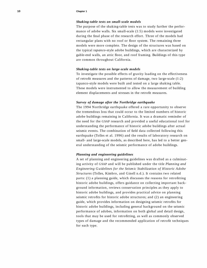
Shaking-table tests on small-scale modelsThe purpose of the shaking-table tests was to study further the perfor-mance of adobe walls. Six small-scale (1:5) models were investigatedduring the final phase of the research effort. Three of the models hadrectangular plans with no roof or floor system. The remaining threemodels were more complete. The design of the structures was based onthe typical tapanco-style adobe buildings, which are characterized bygable-end walls, an attic floor, and roof framing. Buildings of this typeare common throughout California.
Shaking-table tests on large-scale modelsTo investigate the possible effects of gravity loading on the effectivenessof retrofit measures and the patterns of damage, two large-scale (1:2)tapanco-style models were built and tested on a large shaking table.These models were instrumented to allow the measurement of buildingelement displacements and stresses in the retrofit measures.
Survey of damage after the Northridge earthquakeThe 1994 Northridge earthquake offered a rare opportunity to observethe tremendous loss that could occur to the limited numbers of historicadobe buildings remaining in California. It was a dramatic reminder ofthe need for the GSAP research and provided a useful educational tool forunderstanding the performance of historic adobe buildings after actualseismic events. The combination of field data collected following thisearthquake (Tolles et al. 1996) and the results of laboratory research onsmall- and large-scale models, as described here, has led to a better gen-eral understanding of the seismic performance of adobe buildings.
Planning and engineering guidelinesA set of planning and engineering guidelines was drafted as a culminat-ing activity of GSAP and will be published under the title Planning andEngineering Guidelines for the Seismic Stabilization of Historic AdobeStructures (Tolles, Kimbro, and Ginell n.d.). It contains two relatedparts: (1) a planning guide, which discusses the reasons for retrofittinghistoric adobe buildings, offers guidance on collecting important back-ground information, reviews conservation principles as they apply tohistoric adobe buildings, and provides practical advice on planningseismic retrofits for historic adobe structures; and (2) an engineeringguide, which provides information on designing seismic retrofits forhistoric adobe buildings, including general background on the seismicperformance of adobes, information on both global and detail design,tools that may be used for retrofitting, as well as commonly observedtypes of damage and the recommended application of retrofit techniquesfor each type.
10 Chapter 1

The seismic testing research performed during the third year of the GSAP
program was designed to further the understanding of the dynamic per-formance of adobe buildings and changes in that performance when vari-ous retrofit measures are applied. The experimental design was based onthe present state of knowledge and was intended to increase the base ofinformation on the seismic performance of adobe buildings.
The theoretical premise of this testing program was that thecritical features of the seismic performance of historic adobe buildingswill be evident after cracks in the building walls have fully developed.Because the walls are thick, cracking does not necessarily result ininstability of the structure or its individual elements. Retrofit measuressignificantly improve seismic performance when they provide overallstructural continuity, prevent instability, and provide restraint to reducethe relative displacements of cracked wall sections.
Six small-scale model buildings (models 4–9) were tested dur-ing the final phase of the GSAP research program. The first three modelswere similar to those tested during the second year of GSAP. The last threewere more complete, tapanco-style models with gable-end walls, attic floorframing, and a roof system. Three model buildings (models 1–3) weretested during the second year of research (Tolles et al. 1993). A summaryof the data on models 1–9 and their retrofits is listed in table 2.1.
Seismic Retrofit Techniques
The retrofit strategies selected for this testing program were chosenlargely because of their potential for minimizing the post-elastic move-ments of cracked adobe blocks and their minimal impact on the historicfabric of the building. The selection criteria covered a much broader areathan simply the effect on post-elastic performance, however. Criteria usedfor evaluating the strategies included the following:
1. Minimum effect on historic fabric of the structure andreversibility of the retrofit measures
2. Applicability of solutions appropriate to present buildingconditions
Chapter 2
Overview and Procedures for Models 1–9

3. Effectiveness in reduction of severe building damage andlife-safety risks
4. Effectiveness in reduction of damage during moderate tosevere events
5. Cost of retrofit and difficulty of installation6. Use of retrofits for rapid installation in the stabilization of
earthquake-damaged buildings
Any of the measures suggested must have a minimal impact on the build-ing’s historic fabric, and the solutions must be appropriate for the typeof structural systems and for the conditions of these structures observedduring the site survey. Clearly, any seismic retrofit measure should mini-mize risks to life and limb.
12 Chapter 2
Table 2.1
Description of Getty Seismic Adobe Project (GSAP) small-scale model buildings
Model no. SLa Date of tests Walls Type and location of retrofit
GSAP: Second-year research programSimple model: Four walls with no roof systemb
1 7.5 January 1993 NE Upper horizontal strap
SW Upper and lower horizontal straps
2 7.5 January 1993 NE Bond beam and center cores
SW Bond beam plus vertical and horizontal straps
3 7.5 January 1993 NE Bond beam, center cores, and saw cuts; lower horizontal straponly in west pier of north wall
SW Bond beam, center cores, and internal lower horizontal straps
GSAP: Third-year research programSimple model: Four walls with no roof system
4 5 January 1994 NE Upper strap
SW Upper and lower straps
5 11 January 1994 NE Control model, not retrofitted
SW Control model, not retrofitted
6 11 January 1994 NE Bond beam, lower horizontal straps, and vertical straps
SW Bond beam, lower horizontal strap, and local ties
Tapanco-style model: Gable-end walls with attic floor and roof system
7 5 September 1994 NW Partial diaphragms applied on attic-floor and roof framing; upperand lower horizontal and vertical straps
SE Same as the NW walls, except vertical straps placed only on thepiers between the door and window of the north wall
8 7.5 May 1995 NE Partial diaphragms applied on attic-floor and roof framing; upperand lower horizontal and vertical straps
SW Partial diaphragms applied on attic-floor and roof framing; upperand lower horizontal straps and vertical straps; no lower horizon-tal strap on west wall; center-core rods
9 7.5 January 1994 NE Control model, not retrofitted
SW Control model, not retrofitted
aSL is the height-to-thickness (slenderness) ratio of the walls. For models that have more than one story (models 7–9), the slenderness ratio is the height of thewall from the foundation to the attic-floor framing.
bModel previously tested at Stanford University was used as the control for models 1–3 (Tolles and Krawinkler 1989).

Certain solutions may satisfy life-safety requirements, butthe structure may suffer severe damage during a major seismic event.Therefore, the fourth criterion relates to the reduction in the amount ofdamage suffered during moderate to major seismic events. In the evalua-tion of any retrofit, cost and difficulty of installation must be considered.Finally, it is important to develop retrofit techniques that can be safelyused to stabilize earthquake-damaged structures in the time period imme-diately following damaging earthquakes.
From both a life-safety perspective and a conservation per-spective, it is essential to prevent the collapse of buildings during majorseismic events. Because adobe buildings typically have thick walls, thedeflections they can undergo after cracks have fully developed are verygreat compared with the deflections that occur at the point when thebuilding initially cracks. This is particularly true for the out-of-planemotions of these thick walls.
From a conservation perspective, it may also be important toevaluate ways of reducing intermediate levels of damage and to ensurethat a building remains reparable. During a major seismic event, damageto a building may not threaten the life safety of its occupants, but thebuilding may suffer substantial and irreversible damage. Additionalretrofit measures may be added to improve the performance of a particu-lar measure. For example, several measures used in model 8 were designedto minimize the extent of damage during very strong ground motions.
Overview of Tests
The objectives of the tests on models 1–3 were to demonstrate the effec-tiveness of certain stability-based retrofit measures. The objectives of thenext round of tests (models 4–6) were to expand the knowledge of theseismic performance of adobe walls to include the effect of wall thick-ness. Tests on models 7–9 were designed to study more complete struc-tures, such as the tapanco-style building. Models 1–6 were designedprimarily to study the behavior of individual walls both in plane and outof plane, whereas models 7–9 were constructed to simulate the globalbehavior of a complete building system.
The results of the three 1:5 scale-model tests of adobe struc-tures (models 1–3) demonstrated that the use of stability-based retrofitmeasures, which provide continuity and inhibit the relative displacementsof cracked wall sections, can significantly improve the performance of anadobe building. The slenderness ratio (SL)—the ratio of the height of awall to its thickness—in these models was 7.5 (see Tolles et al. 1993).(The shorter the height, the lower the ratio. A thick-walled adobe build-ing would typically have an SL of about 5, whereas a thin-walled adobemight have an SL of 10 or 11.)
The tests on models 4, 5, and 6 were performed to determinethe effects of wall thickness on seismic behavior. Model 4 (SL 5 5) wasdesigned with a retrofit similar to that of model 1 (SL 5 7.5). Model 5(SL 5 11) was the unretrofitted control model for model 6 (SL 5 11),
Overview and Procedures for Models 1–9 13

which was tested with retrofit measures similar to those used in model 2(SL 5 7.5). Although there were some important differences in the behav-ior of models with different slenderness ratios, the specific retrofit systemused was the dominant factor in the performance of these models. Wallthickness in the tested range turned out to be a secondary factor thatinfluenced model behavior significantly only during very strong groundmotions. In general, thicker walls improved the post-elastic performancebecause of the stability inherent in massive, low-to-the-ground walls.
Models 7–9 were more complete buildings. These modelswere constructed with the tapanco-style building elements. Model 7(SL 5 5) was tested first and demonstrated the effectiveness of the retrofitsystem. Models 8 and 9 were constructed with thinner walls (SL 5 7.5)than those of model 7. The retrofit system used on model 8 was similarto that of model 7, except fiberglass center-core rods were installed intwo adjacent walls. Model 9 was the unretrofitted control model used forcomparison with the performance of model 8. In general, the retrofit sys-tems used in models 7 and 8 were extremely effective and greatlyimproved overall seismic response.
Models 10 (unretrofitted) and 11 (retrofitted) were basicallyof the same design as tapanco models 9 and 8, respectively, except themodel scale was increased from 1:5 to 1:2. The objective of these testswas to determine if gravity loads would affect the nature of the in-planeand out-of-plane wall motions and to assess the effectiveness of theretrofits in minimizing damage.
Description of Materials and Models
Adobe materialThe adobe bricks and mortar for the models were made from a 1:5 mix-ture of clay and sand. These materials and the bricks’ manufacture werechosen for their similarity to those used in previous Stanford testing(Tolles and Krawinkler 1989) so complementary results could beobtained. The clay was a pulverized, commercially available material thatwas mixed with well-graded silica and placed wet into molds. The moldswere later removed and the bricks allowed to air-dry.
The brick-strength parameters were designed to be similar tothose of an “average” adobe material found in Mexico, as in the earlierStanford tests. During the previous test program, tests were performed todetermine (1) flexure and compressive strength of the adobe material; (2)flexure of the individual bricks; and (3) flexure, compression, and diago-nal tension of the brick assemblies. The compressive strength of themodel assemblies was less than that of the prototype, but the moreimportant flexural and diagonal tension properties were nearly the same.
Model design and constructionThe walls of each model were one wythe (a single adobe brick) thick andconstructed with a running bond. The length of the bricks was 7.9 cm(3.1 in.), the width dependent on the thickness of the walls, and the thick-
14 Chapter 2

ness of the bricks was 2.3 cm (0.9 in.). In the thin-walled models (models5 and 6), the bricks were 5.3 cm (2.1 in.) wide, and the bricks in the wallsof models 1–3 and models 8 and 9 were 7.9 cm (3.1 in.) wide. The bricksin the thick walls of models 4 and 7 were 11.7 cm (4.6 in.) wide. Themortar was made of the same clay:sand mixture as the adobe bricks.
The models were constructed on one of three concrete bases.After construction and drying for a minimum of 30 days, each modelwas transported to the shaking table. Steel dowels, cast into the concretebase, were projected into the first two courses of adobe. These dowelswere used to limit slipping of the model along the base; slippage at thebase would be expected in these models because the vertical loading wasnot fully simulated in the “gravity forces neglected” models used in thisresearch project. Wood lintels, the thickness of one course of adobe, wereused over all door and window openings.
Retrofit measuresThe retrofit measures on the model buildings included horizontal ele-ments and, usually, vertical elements. The horizontal elements were eithernylon straps, a bond beam, or a partial wood diaphragm. The verticalelements were either nylon straps, center-core rods, or local ties.
The wood bond beams used on models 3 and 6 were made ofDouglas fir and were 3.8 cm (1.5 in.) wide and 1.0 cm (0.375 in.) thick.The bond beams were anchored to the walls with 0.3 cm (0.125 in.)diameter by 8.9 cm (3.5 in.) long coarse-threaded screws. The holes forthe screws were predrilled before placement.
The vertical and horizontal straps were made of a 0.3 cm(0.125 in.) wide, flexible, woven nylon strap typically used for a bootlace.The straps always formed a loop either around the entire building oraround an individual wall. The straps were passed through small holes inthe wall and the two ends were knotted together. Exterior straps werefound to have been useful for stabilizing some Guatemalan adobes follow-ing the major earthquake in that region in 1976 (Molino de Garcia 1990).
Crossties were made of 0.16 cm (0.062 in.) diameter nyloncord and were installed to reduce the differential displacement acrosscracks. Also, when vertical and horizontal straps were installed on bothsides of a wall, crossties were added to provide a through-wall connec-tion. The crossties were inserted through small holes in the wall togreatly reduce the displacement that could occur perpendicular to theplane of the wall. Flat nylon straps that are commonly used in electricalwork and referred to as cable ties were also used as crossties.
Although stresses in the crossties and vertical or horizontalstraps were not measured on the 1:5 scale models, none of the straps orcrossties failed during any of the tests. The static breaking load of thenylon straps was 102 kg (225 lb.) and the breaking load of the cable tieswas 27 kg (60 lb.).
The center-core elements used in models 2 and 3 were 0.3 cm(0.125 in.) diameter steel drill rods. The rods were drilled directly intothe adobe after flattening each end into a V-shaped form. The rods,which were left in place after drilling, functioned well throughout the
Overview and Procedures for Models 1–9 15

testing sequence and were adequate for providing shear dowels betweenthe cracked sections of the walls.
The center-core elements in model 8 were 0.48 cm (0.188 in.)diameter steel rods anchored with an epoxy grout. The holes were drilledwith a 0.6 cm (0.25 in.) diameter drill bit, but, given the coarseness ofthe sand in the adobe mixture, the actual diameter of the holes wasapproximately 1.0 cm (0.375 in.). After the testing, one rod was removedfrom the wall, and the epoxy core was found to be nearly 1.3 cm (0.5 in.)in diameter. Essentially, then, this was the effective center-core diameter.
All center-core rods were located entirely within the adobewall and were not connected to the concrete base. When used in conjunc-tion with wood bond beams, the rods were anchored to the bond beamwith an epoxy resin.
Model similitudeModeling theory establishes the rules by which the geometry, materialproperties, initial conditions, and boundary conditions of the model andthe prototype can be related. The laws of similitude for linear elasticbehavior are based on well-established principles of dimensional analysisand lead to the development of a complete set of correlation functions(scaling laws) that define the model-prototype relationship. A listing ofsimilitude requirements is given in table 2.2.
16 Chapter 2
Model scaling parametersa Model type
Artificial mass Gravity forces True replica simulation neglected
Length lr lr lr lr
Time tr lr1/2 lr
1/2
Frequency vr lr21/2 lr
21/2
Velocity nr lr1/2 lr
1/2
Gravitationalacceleration gr 1 1 neglectedb
Acceleration ar 1 1
Mass density rr Er/lr augmentedc rr
Strain er 1 1 1
Stress sr Er Er Er
Modulus of elasticity Er Er Er Er
Displacement dr lr lr lr
Specific stiffness lr augmented
Force Fr Er lr2 Erlr
2 Erlr2
Er_ +
rEr_ +
r
Er_ +
rlr
21
Er_ +
r
1/2
lr Er_ +
r
1/221
lr 5 Er_ +
r
21/2
Table 2.2
Similitude requirements
From Moncarz and Krawinkler 1981.aSubscript notation: m 5 model; p 5 prototype; r 5 ratio between model and prototype (e.g., ).bEffects of gravity are neglected; this modeling theory assumes that the effects of gravityforces are minor and are negligible.cMass of the building augmented by adding additional, structurally ineffective mass to the building.
lr 5 lmlp

The models used in this study are referred to as “modelswithout the simulation of gravity loads.” The same type of model wasused in previous Stanford research. The model-prototype relationship isclearly defined during the time when the adobe material is still in theelastic range. This type of model is accurate up to the point at whichcracks develop because the vertical loads are small and have minoreffects on the elastic stresses in walls of single-story structures.
When a building is damaged and becomes inelastic, the accu-racy of the model is more difficult to assess. Overturning of individualwalls is not properly modeled because gravity forces resist overturning.Also, sliding along cracks is not accurately simulated in the “gravityforces neglected” model, shown in table 2.2. Resistance to sliding isdirectly proportional to the vertical stresses, which are smaller becausegravity loads are not fully simulated. Such resistance is also affected bythe increased frequency characteristics of the model and by inputmotions (Tolles and Krawinkler 1989).
The problems discussed here were not considered to be ofprimary importance since the purpose of research on the small-scalemodels was to study the global response characteristics of the modelsand to evaluate the relative merit of the different retrofit measures.Because the linear elastic modeling of a single-story adobe building isnearly exact, the crack patterns should be nearly the same as those foundin the prototype. The response of the cracked models will contain theglobal characteristics of the prototype, even though overturning willoccur at lower levels and frictional resistance along cracks may be lower.
A roof system was not included on models 1–6 because theprimary purpose of these tests was to study the in-plane and out-of-planeperformance of individual walls. Performance could be studied moreindependently by not including a roof system that would directly couplethe load-bearing walls. If a roof system had been included, it might haveaffected the behavior of the models.
A roof system was included in models 7–9, however, todetermine the extent of any behavioral differences. The 1:5 scale andthe slenderness ratio were chosen because they were identical to sixmodels tested at Stanford University in the mid-1980s (Tolles andKrawinkler 1989).
Description of Test Procedure
Test setupThe small-scale models were tested on the shaking table at the John A.Blume Earthquake Engineering Center at Stanford University. The shak-ing table is 1.52 m (5.0 ft.) square and has a uniaxial motion withmaximum displacements of 7.6 cm (3 in.). Because the scale of themodels was 1:5, the maximum displacements in the prototype domainwere 38 cm (15 in.). Displacement capacity is a critical feature in deter-mining a shaking table’s ability to cause out-of-plane collapse of thick-walled buildings.
Overview and Procedures for Models 1–9 17

Each model was built on a 1.67 m (5.5 ft.) square concreteslab and allowed to dry for a minimum of 30 days. The models weretransported and secured to the shaking table the day before testingbegan. Four 30 cm (12 in.) square plywood blocks were placed on theshaking table. Cement mortar was placed between each block and theconcrete slab to allow for leveling and equal contact at each block. Afterthe mortar was allowed to cure overnight, the slab was anchored to thetable using four 45 cm (18 in.) long by 2.2 cm (0.875 in.) diameter boltsattached to the top of the slab and anchored to two 10 cm (4 in.) squaretimbers placed on the underside of the shaking table.
InstrumentationInstrumentation for these tests was kept to a minimum. The goal of thetesting program was to maximize the number of tests that could be per-formed and to make a qualitative evaluation of the performance of themodels based on visual observations. The displacements and accelera-tions of the shaking table were measured to verify the proper perfor-mance of the table and for comparison with previous testing. Thedisplacements were measured using the linearly variable differentialtransformer (LVDT) that is part of the shaking table. Accelerations weremeasured at the top of the shaking table and at the top of the concreteslab to check for slippage between the table and slab. No other quantita-tive measurements were collected.
Simulated earthquake motionsThe earthquake motion used in these tests was based on the N21E com-ponent of the 1952 Taft earthquake in Kern County, California. Eachmodel was subjected to a series of ten simulated earthquake displace-ment motions. Each subsequent displacement motion was 20–30%larger than the previous one. The displacement, velocity, and accelera-tion records for the N21E component of the Taft earthquake are pre-sented in figure 2.1. The maximum simulated earthquake motion was6–7 times larger than the original earthquake, based on comparison ofthe displacement records.
A listing of the ten simulated earthquake motions is presentedin table 2.3. The estimated peak ground acceleration (EPGA) is similar tothe actual peak ground acceleration (PGA) except that the EPGA is deter-mined from the response spectrum between 2 and 8 hertz (Tolles andKrawinkler 1989).
Test level is used to describe the intensity of a test in termsof peak displacement and acceleration. In most model tests, the sequencewas linear from test level I to test level X. This was not true for allbuildings. The test sequence for model 5 skipped from test level V to testlevel VIII in an attempt to accelerate the collapse. In many buildings, testlevel X was repeated more than once. In these cases, the first repetitionis noted as test level X(1) and the second as test level X(2). Test level IXwas repeated twice in the test sequence for model 8.
Test levels VIII, IX, and X represented very large groundmotions. In the prototype domain, the peak horizontal displacement for
18 Chapter 2

test level X was 38.1 cm (15 in.), and the peak acceleration was approx-imately 0.58 g. The peak accelerations for the higher test levels were notfully replicated by the table motions because of the shaking table’sinability to represent stronger ground motions. Nevertheless, the higherfrequency component of the table motion was not important at thehigher test levels because of the damage that had already been sustainedby the model buildings. Because peak accelerations are often used as ameans of comparison, if the table had been capable of fully duplicatingthe earthquake, the peak acceleration for test level X would have beenbetween 0.8 g and 0.9 g. Nevertheless, the Taft earthquake record has asubstantial high-frequency component, and complete simulation of thehigh-frequency component during the larger table motions would prob-ably not be accurate.
The higher level tests were at the upper end of what mightbe expected during the most severe earthquake in California. A dynamicdisplacement of 38.1 cm (15 in.) is very large but definitely possible.Even if the tests were carried out at a slightly greater acceleration thanthat experienced in the largest possible earthquake, they represent aneffective means of testing the resilience of the proposed retrofit strategies.
Overview and Procedures for Models 1–9 19
Max. 5 22.118 at 13.25 sec.3.00
2.00
1.00
0.00
21.00
22.00
23.000.0 5.0 10.0 15.0 20.0
Time (sec.)
Dis
pla
cem
ent (
in.)
Max. 5 0.155 at 9.24 sec.
0.0 5.0 10.0 15.0 20.0Time (sec.)
Acc
eler
atio
n (g
)
Max. 5 26.189 at 3.454 sec.
0.0 5.00 10.00 15.00 20.00Time (sec.)
Velo
city
(in
./sec
.)
6.00
4.00
2.00
0.00
22.00
24.00
26.00
0.20
0.10
0.00
20.10
20.20
Figure 2.1
Graph of N21E component of 1952 Taft
earthquake (displacement, velocity, and
acceleration).

In addition, the quality of laboratory-built models generally is higherthan that found in the field, whether due to the original construction orto subsequent damage. Therefore, it was important to test these “high-quality” models with powerful earthquake forces.
The duration of the ground motion was 20 seconds in theprototype domain. This is a long duration for the lower test levels but ashort duration for the higher levels. An earthquake of magnitude 8 onthe Richter scale might last longer than a minute. Even though thesemodel buildings were subjected to repeated ground motions, whichcaused cumulative damage to the models, the combined effect of testsVIII, IX, and X may be a reasonable representation of the largestexpected ground motions in the California area.
The model buildings were subjected only to uniaxial motion.This shaking mode is preferred during tests that are used to isolate thedynamic characteristics of the models. All models were shaken in an east-west direction.
DocumentationThe behavior of the models was documented using drawings, photo-graphs, and videotape. The acceleration and displacement of each testwere recorded digitally. Still photographs were taken of each wall of themodel to record the damage after every test.
The dynamic motion of all model walls was recorded onvideotape. Four video cameras aimed at each of the four wall intersec-tions were used to record the motion of adjacent walls. The dynamicmotion of these tests lasted a little longer than 4 seconds, which wasequivalent to 20 seconds in the prototype domain. It was important torecord the dynamic motions of the models from all angles to be able tostudy the wall motions after the testing was completed.
During a test sequence, the cracks that developed were num-bered as they appeared. The number of each crack coincided with thenumber of the test in which the crack occurred.
20 Chapter 2
Test Maximum EPGAa Maximum displacementlevel (g) cm in.
I 0.12 2.54 1.00
II 0.18 5.08 2.00
III 0.23 7.62 3.00
IV 0.28 10.16 4.00
V 0.32 12.70 5.00
VI 0.40 15.88 6.25
VII 0.44 19.05 7.50
VIII 0.48 25.40 10.00
IX 0.54 31.75 12.50
X 0.58 38.10 15.00
Table 2.3
Simulated earthquake motions for testing
(dimensions in the prototype domain)
aEstimated peak ground acceleration

The purpose of the tests on models 4–6 was to investigate the effect ofthe slenderness ratio of the walls on the performance of the model build-ings. Model 5 was unretrofitted, and models 4 and 6 were retrofitted.Because only one model was not retrofitted, the evaluation of the effectof wall thickness was based primarily on the performance of theretrofitted models.
Description of Models
Retrofit strategies used on models 1 and 4 were similar. The measuresused on models 2 and 6 were also similar. Details of the tests and resultson models 1–3 are given in the GSAP second-year report (Tolles et al.1993:3.39–75).
The only difference between the retrofits of models 1 (SL 5 7.5) and 4 (SL 5 5.0) was the spacing of the crossties. A fewadditional ties were added to model 4 in areas where crack displace-ments had been large during the higher-level tests performed on model 1.
The differences between models 2 and 6 were moresignificant. Each model had a wood bond beam, and two walls of eachmodel were retrofitted with vertical straps. In model 2, the east andnorth walls had steel center-core rods. In model 6, the south and westwalls were fitted with only local crack ties, which were installed to evalu-ate the possibility of the use of a less invasive approach. For the mostpart, the use of local crack ties was not successful. In model 3, all wallscontained center cores.
The general layout of the models is shown in figure 3.1.Each wall had a door and a window. The door was located near thecenter of the wall, and the windows were located close to the southwestand northeast corners. The same retrofit was used on two adjacentwalls, allowing simultaneous evaluation of a specific retrofit on both in-plane and out-of-plane walls. Table motion was uniaxial in an east-westdirection.
Model 4 (SL 5 5)The retrofit on model 4 consisted of upper horizontal straps applied toboth sides of all four walls and an additional lower horizontal strap on
Chapter 3
Description of Tests for Models 4–6

the south and west walls. The upper horizontal strap was located atapproximately the midpoint between the top of the wall and the top ofthe door and window openings. The lower horizontal strap on the southand west walls was located at approximately two-thirds the distancefrom the foundation to the bottom of the windows.
Horizontal straps were located on both sides of each wall.Crossties were placed at points approximately 10 cm (4 in.) on center,and connected straps on opposite sides of the walls.
The retrofits installed on model 4 were the same as those onmodel 1. Model 1 performed through test level IX and collapsed duringtest level X. Model 4 was designed to determine whether the effectivenessof this retrofit strategy could be improved when used on a model withthicker walls.
Model 5 (SL 5 11)Model 5 was used as an unretrofitted, thin-wall control model and hadthe same layout as models 1–4 and 6.
Model 6 (SL 5 11)The retrofits used on model 6 were similar to those used on model 2; thenorth and east walls (see fig. 3.1) were retrofitted in an identical manner.A bond beam was applied at the top of all four walls in addition to thevertical straps and lower horizontal straps that were applied to two ofthe walls (the north and east walls in model 6 and the south and westwalls in model 2). Small-diameter center-core rods were used in the north
22 Chapter 3
Upper horizontal strap on both sides of each of the four walls
South wall
East wallLower horizontal strap on south and west walls
West wall
North wall
Model 4
Model 6
Bond beam on all four walls
Vertical and lower straps on north and east walls
South wall
Local crack ties in west and south walls
East wallWest wall
North wallFigure 3.1
General layout of models 4 and 6, show-
ing inner and outer wall straps connected
through the wall by thin nylon cords at
15.2–20.3 cm (6–8 in.) intervals.

and east walls of model 2, but rods were not installed in model 6 becausethe walls were too thin to allow accurate placement. Instead, the southand west walls of model 6, which were more lightly retrofitted than thenorth and east walls, were retrofitted with local crack ties to connect thepredicted major wall segments. Lower horizontal straps were used onthis model. Local crack ties were used for connections across locationswhere cracks were anticipated.
Test Results for Model 4
Model 4 (SL 5 5) performed well throughout the testing sequence,although it nearly collapsed during test level X (table 3.1). The conditionof the model following selected tests is shown in figures 3.2–3.7.
Damage began during test level IV when cracks developedprimarily in the in-plane walls (fig. 3.2). The thick walls (SL 5 5) resistedthe out-of-plane motions, but the in-plane forces exceeded the strengthof the adobe.
The development of the primary system of cracks was com-pleted during test levels V and VI (figs. 3.3 and 3.4). At this point in thetest sequence, the retrofit system became active.
Although no thick-walled (SL 5 5) control model was tested,it would appear that an unretrofitted model (SL 5 5) would have col-lapsed during test level VII (fig. 3.5) or VIII. During these tests, theretrofit system was very active, and the cracked wall sections began toundergo permanent displacements.
Prior to test level IX, local crack ties were added to eachof the piers between the doors and windows because of the permanent
Description of Tests for Models 4–6 23
Test EPGAa Peak displacementlevel (g) cm in. Comments
III 0.23 7.62 3.00 No damage
IV 0.28 10.16 4.00 Crack initiation primarily inthe in-plane walls
V 0.32 12.70 5.00 Further crack development
VI 0.40 15.88 6.25 Complete crack systemdevelopment
VII 0.44 19.05 7.50 Retrofit system fully active
VIII 0.48 25.40 10.00 Permanent displacement ofwindow-door pier blocks
IX 0.54 31.75 12.50 Local crack ties added to pierblocks; building system per-forms well
X 0.58 38.10 15.00 Near-collapse of east wall;substantial permanent dis-placements throughout themodel
Table 3.1
Model 4: Test sequence and commentary
(prototype dimensions)
aEstimated peak ground acceleration

24 Chapter 3
(a)
(b)
(c)
(d)
Figure 3.2
Model 4, test level IV, showing (a) east
wall (out of plane); (b) north wall (in
plane); (c) west wall (out of plane); and
(d) south wall (in plane). Crack initiation
occurred, with crack pattern in walls
showing little differentiation between in-
plane and out-of-plane directions. Cracks
in the in-plane walls (north and south)
started at the corners of openings and at
the pier between door and window. In the
out-of-plane direction, the west wall sus-
tained crack damage in several locations,
while the east wall had only one crack,
extending diagonally from the bottom of
the window toward the lower north cor-
ner. Note that in this thick-walled model,
cracks began in the in-plane walls.

Description of Tests for Models 4–6 25
(a)
(b)
(c)
(d)
Figure 3.3
Model 4, test level V, showing (a) east
wall (out of plane); (b) north wall (in
plane); (c) west wall (out of plane); and
(d) south wall (in plane). Some additional
cracks were initiated in the in-plane walls
and the east, out-of-plane, wall. No addi-
tional crack damage was observed in the
west wall. At this point in the testing,
dynamic displacements remained small
and the retrofit system (horizontal straps)
had little or no effect on the model’s
performance.

26 Chapter 3
(a)
(b)
(c)
(d)
Figure 3.4
Model 4, test level VI, showing crack
damage in (a) east wall (out of plane);
(b) north wall (in plane); (c) west wall (out
of plane); and (d) south wall (in plane).
Although cracking remained nearly con-
stant from that of test level V, the motion
of the cracked wall sections became sub-
stantially larger during this test level as
the cracks began to open up and the wall
sections started to move relative to one
another. There was little rocking of the
cracked wall sections in the out-of-plane
walls. The retrofit straps were engaged
during this test sequence.
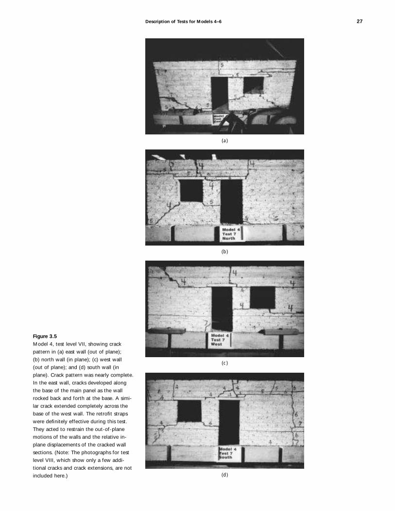
Description of Tests for Models 4–6 27
(a)
(b)
(c)
(d)
Figure 3.5
Model 4, test level VII, showing crack
pattern in (a) east wall (out of plane);
(b) north wall (in plane); (c) west wall
(out of plane); and (d) south wall (in
plane). Crack pattern was nearly complete.
In the east wall, cracks developed along
the base of the main panel as the wall
rocked back and forth at the base. A simi-
lar crack extended completely across the
base of the west wall. The retrofit straps
were definitely effective during this test.
They acted to restrain the out-of-plane
motions of the walls and the relative in-
plane displacements of the cracked wall
sections. (Note: The photographs for test
level VIII, which show only a few addi-
tional cracks and crack extensions, are not
included here.)

28 Chapter 3
(a) (b)
(c) (d)
Figure 3.6
Model 4, test level IX, showing crack
damage to (a) east wall (out of plane);
(b) north wall (in plane); (c) west wall
(out of plane); and (d) south wall (in
plane). (Test level cracks are not marked
on east and west walls; see Fig. 3.7a and
c.) Before this test level, local crack ties
were added to the pier blocks between the
doors and windows because of the large
displacements sustained during test level
VIII. During test levels VIII and IX, rocking
of the wall sections was greatly restrained
by the upper horizontal strap. This
restraint generated additional horizontal
cracks in the large panel to the left of the
door in the east wall at about one-third
height.
offsets sustained during test level VIII. These blocks were pushed backinto position before the ties were applied. The model behaved well dur-ing test level IX (fig. 3.6), although there were permanent offsetsbetween many cracked wall sections.
The model nearly collapsed during test level X (fig. 3.7). Theeast wall was leaning outward at the end of the test. The wood lintelover the door of the east wall was dislodged, and the adobe block aboveit was nearly dislodged.
Test Results for Model 5
Model 5 was an unretrofitted control model, tested to demonstrate thevulnerability of unretrofitted adobe walls with SL 5 11. Cracks began toform during test level III (fig. 3.8), and the crack pattern fully developedduring test level V (fig. 3.9) with the formation of flexural cracks in theout-of-plane walls and shear cracks in the in-plane walls (test level IVwas omitted; table 3.2). Considerable rocking was observed during thistest. The sequence was advanced to test level VIII, the fifth test in thisseries, which resulted in the complete collapse of the east wall and mostof the west and south walls (fig. 3.10). The north wall was severely dam-aged, and the eastern corner was completely destroyed.

Description of Tests for Models 4–6 29
Figure 3.7
Model 4, test level X, showing damage to
(a) east wall (out of plane); (b) north wall
(in plane); (c) west wall (out of plane);
and (d) south wall (in plane). The model
nearly collapsed at this test level. The east
wall was leaning outward, and the west
wall would have fallen if not for the upper
horizontal strap. The wood lintel over the
window in the north wall was dislodged.
A horizontal crack in the upper portion
of the walls extended around the entire
model. The piers between the door and
window on both east and west walls were
held in place by local ties that were added
after test level IX.
(a)
(b)
(c)
(d)

30 Chapter 3
(a)
(b)
(c)
(d)
Figure 3.8
Model 5, test level III, showing (a) east
wall (out of plane); (b) north wall (in
plane); (c) west wall (out of plane); and
(d) south wall (in plane). Minor cracking
is seen with little visible out-of-plane wall
displacement. Similar types and numbers
of cracks developed in both in-plane and
out-of-plane walls.

Description of Tests for Models 4–6 31
(a) (b)
(c) (d)
Figure 3.9
Model 5, test level V (fourth in the test
sequence), showing cracking in (a) east
wall (out of plane); (b) north wall (in
plane); (c) west wall (out of plane); and
(d) south wall (in plane). Fully developed
crack pattern is visible with flexural cracks
in the out-of-plane walls and shear cracks
in the in-plane walls. The walls rocked
noticeably during the test but did not
collapse.
Test EPGAa Peak displacementlevel (g) cm in. Performance summary
I 0.12 2.54 1.00 No damage
II 0.18 5.08 2.00 No damage
III 0.23 7.62 3.00 Crack initiation
V 0.32 12.70 5.00 Full crack pattern develop-ment; near collapse
VIII 0.48 25.40 10.00 Collapse of 75% of the walls;complete collapse of out-of-plane walls
Table 3.2
Model 5 (control model): Test sequence
and performance summary (prototype
dimensions)
Test Results for Model 6
As expected, the performance of the retrofitted model 6 was much betterthan that of model 5. During test levels III–V, the crack patterns weresimilar to those of the unretrofitted model (table 3.3; figs. 3.11–3.13).Large flexural, yield-line cracks developed in the east and west walls,which demonstrated that the bond beam had little effect on the elasticbehavior of the model. Few additional cracks developed between testlevels IV and VI.
aEstimated peak ground acceleration
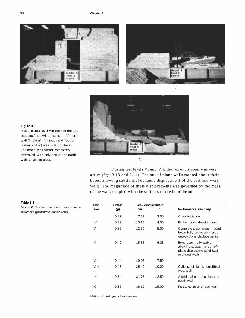
During test levels VI and VII, the retrofit system was veryactive (figs. 3.13 and 3.14). The out-of-plane walls rotated about theirbases, allowing substantial dynamic displacement of the east and westwalls. The magnitude of these displacements was governed by the massof the wall, coupled with the stiffness of the bond beam.
32 Chapter 3
(a) (b)
(c)
Figure 3.10
Model 5, test level VIII (fifth in the test
sequence), showing results on (a) north
wall (in plane); (b) south wall (out of
plane); and (c) west wall (in plane).
The model was almost completely
destroyed, with only part of the north
wall remaining erect.
Test EPGAa Peak displacementlevel (g) cm in. Performance summary
III 0.23 7.62 3.00 Crack initiation
IV 0.28 10.16 4.00 Further crack development
V 0.32 12.70 5.00 Complete crack system; bondbeam fully active with largeout-of-plane displacements
VI 0.40 15.88 6.25 Bond beam fully active,allowing substantial out-of-plane displacements of eastand west walls
VII 0.44 19.05 7.50
VIII 0.48 25.40 10.00 Collapse of lightly retrofittedwest wall
IX 0.54 31.75 12.50 Additional partial collapse ofsouth wall
X 0.58 38.10 15.00 Partial collapse of east wall
Table 3.3
Model 6: Test sequence and performance
summary (prototype dimensions)
aEstimated peak ground acceleration

Description of Tests for Models 4–6 33
(a)
(b)
(c)
(d)
Figure 3.11
Model 6, test level III, showing (a) east
wall (out of plane); (b) north wall (in
plane); (c) west wall (out of plane); and
(d) south wall (in plane). Initial cracking is
visible, and a classic flexural pattern was
observed in the east wall, though only
small cracks were observed in the west
wall. No cracks developed in the north
wall, and only two or three slight cracks
developed in the south wall.

34 Chapter 3
(a)
(b)
(c)
(d)
Figure 3.12
Model 6, test level IV, showing (a) east
wall (out of plane); (b) north wall (in
plane); (c) west wall (out of plane); and
(d) south wall (in plane). A more complete
crack pattern is apparent, particularly in
out-of-plane walls. Flexural displacements
at the tops of these walls are clearly
visible. Spalling at the top of the west wall
is indicative of large displacement motions;
the diagonal cracks in the large solid wall
sections of both east and west walls are
typical of flexural cracking. Damage to
the north and south walls is still relatively
minor. The horizontal crack in the upper
right corner of the north wall is typical
of cracking in walls reinforced with a
bond beam.
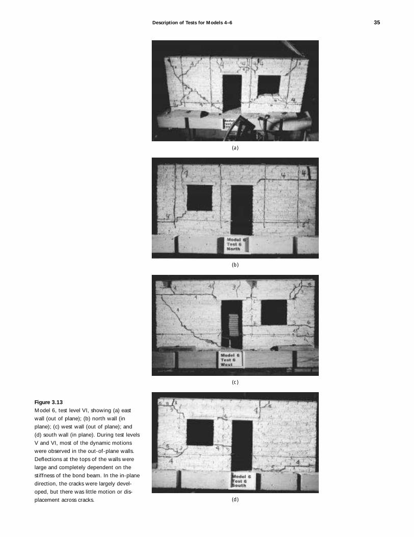
Description of Tests for Models 4–6 35
(a)
(b)
(c)
(d)
Figure 3.13
Model 6, test level VI, showing (a) east
wall (out of plane); (b) north wall (in
plane); (c) west wall (out of plane); and
(d) south wall (in plane). During test levels
V and VI, most of the dynamic motions
were observed in the out-of-plane walls.
Deflections at the tops of the walls were
large and completely dependent on the
stiffness of the bond beam. In the in-plane
direction, the cracks were largely devel-
oped, but there was little motion or dis-
placement across cracks.

36 Chapter 3
(a)
(b)
(c)
(d)
Figure 3.14
Model 6, test level VII, showing (a) east
wall (out of plane); (b) north wall (in
plane); (c) west wall (out of plane); and
(d) south wall (in plane). Spalling at the
top of the east and west walls is indicative
of large out-of-plane displacements. Some
additional minor cracks developed during
this test. In-plane displacements of north
and south walls became more substantial,
but little new cracking developed. Some
small permanent displacements occurred at
the end of this test.

In test level VIII, the lightly retrofitted west wall collapsed(fig. 3.15). Local crack ties had been applied at several locations butwere not effective in preventing out-of-plane collapse.
A portion of the in-plane south wall collapsed (fig. 3.16) dur-ing test level IX. Nevertheless, the two sections of the north wall thatwere retrofitted with vertical straps continued to perform well.
Most portions of the north and east walls performed wellthrough test level X (fig. 3.17). The walls did not collapse nor was thebuilding in the unstable condition noted for model 4 after test level X.The pier between the door and window was dislodged during the testand was suspended by the vertical straps. There were insufficient dis-placement controls on this pier to prevent it from being dislodged.
Summary of Test Results for Models 4–6
Model 4 performed well throughout the testing sequence despite its nearcollapse during test level X. The performance of models 1 and 4 werenearly the same, even though model 1 did collapse during test level X.The horizontal straps clearly had a positive effect on providing stabilityfor both the in-plane and out-of-plane walls of these models.
The unretrofitted model 5 collapsed early in the testsequence, as expected. The model was not able to sustain motions much
Description of Tests for Models 4–6 37
(a) (b)
(c) (d)
Figure 3.15
Model 6, test level VIII, showing (a) east
wall (out of plane); (b) north wall (in
plane); (c) west wall (out of plane); and
(d) south wall (in plane). Dynamic motions
of the model were substantial. During test
levels VI and VII, stability of the out-of-
plane walls was dependent on the bond
beam. During test level VII, out-of-plane
stability became dependent on both the
bond beam and the vertical straps. Col-
lapse of the west wall by overturning
started below the horizontal crack that
formed during test level IV at the north
end of the west wall. The north and south
walls were also subjected to substantial
movement, resulting in significant perma-
nent displacements. Relative displacements
of cracked wall sections were less severe in
the north wall, which had vertical straps,
than in the south wall, which had only
local through-ties.

greater than those that caused the initial cracking; it survived only onetest beyond the fully developed cracked state.
Model 6 (and all other retrofitted models) behaved much bet-ter than the control model. The walls with vertical straps (north and eastwalls) behaved considerably better than the south and west walls, whichhad only local ties. The south and west walls collapsed during test levelVIII; the bond beam and the local crack ties improved the performanceof the walls slightly but did not provide sufficient stability to prevent col-lapse. The north and east walls behaved very well through test level IX,but the east wall suffered partial collapse during test level X. The behav-ior of the north and east walls may have been negatively affected by theearlier collapse of the south and west walls because they would have pro-vided some support, particularly at the south end of the east (out-of-plane) wall.
The behavior of model 2 (SL 5 7.5) and model 6 (SL 5 11)was similar, although the performance of model 2 was clearly morerobust due to the additional stability provided by the thicker walls. Theaddition of vertical straps improved the stability of the north and eastwalls compared to that of the south and west walls, where only localcrossties were used in conjunction with the bond beam.
The most significant difference between the dynamic behaviorof model 2 (SL 5 7.5) and model 6 (SL 5 11) was observed in the post-
38 Chapter 3
(a) (b)
(c) (d)
Figure 3.16
Model 6, test level IX, showing (a) east
wall (out of plane); (b) north wall (in
plane); (c) west wall (out of plane), col-
lapsed at test level VIII; and (d) south wall
(in plane). The test sequence continued,
despite the collapse of the west wall,
which undoubtedly compromised the
structural performance of the south wall.
Nevertheless, the continuous successful
performance of the north and east walls
demonstrated the robustness of the
retrofit system used on these two walls.
The east wall again showed large displace-
ments, but the dynamics of the wall was
also largely affected by displacements of
the in-plane walls. Overall displacements
in the north wall were smaller than those
in the south wall. Local ties have some
overall stabilizing influence but seem to be
relatively poor as displacement controls.

elastic dynamic behavior before collapse occurred. After cracks devel-oped, but before stability became a problem (during test levels V–VII),the out-of-plane walls of model 6 showed considerable amplification ofthe dynamic motion. The frequency of the out-of-plane motion wasattributed primarily to the stiffness of the bond beam and the tributarymass of the adobe wall.
In evaluating the effect of wall thickness on the seismicbehavior of the retrofitted models, the following conclusions were drawnfrom these tests:
1. The effect of the installed retrofit systems was of primaryimportance compared to the overall effect of an increasein wall thickness.
2. The difference in the performance between thin-walledand thick-walled adobe buildings should not be dis-counted, however. There were some obvious differencesin the dynamic behavior of the thin-walled (SL 5 11)models compared to that of the thick-walled (SL 5 5)models, and the latter required a much lighter interven-tion than the former.
3. The post-elastic behavior of the thin, out-of-plane walls(SL 5 11) was controlled by the dynamic characteristics of
Description of Tests for Models 4–6 39
(a) (b)
(c) (d)
Figure 3.17
Model 6, test level X, showing (a) east
wall (out of plane); (b) north wall (in
plane); (c) west wall (out of plane);
and (d) south wall (in plane). Model
approached complete collapse. The north
wall behaved well, the bond beam and
vertical straps being quite effective. On
the east wall, the vertical strap on the cen-
tral pier did not provide enough stability
to prevent collapse. The remainder of the
east wall degraded severely, showing that
this type of retrofit system for walls with
SL 5 11 is not as robust as on walls with
SL 5 7.5 (model 2), which withstood sev-
eral repetitions at test level X.

the wood bond beam. The restraint at the base of thewall, which controlled the rocking of wall sections, wasnegligible compared to the restraint provided by the bondbeam. Therefore, the dynamic motion at the top of thewall could be closely estimated by using the tributarymass and the stiffness of the bond beam.
4. In contrast, the out-of-plane behavior of the walls ofmodel 2 (SL 5 7.5) did not demonstrate the same dynamicamplification as that of model 6 (SL 5 11). The dynamicmotion of the out-of-plane walls of model 2 was con-trolled primarily by the rotational restraint against rock-ing at the base of the wall.
40 Chapter 3

The models and tests discussed in the previous chapters were designedprimarily to study the behavior of adjoining adobe walls during and fol-lowing simulated seismic excitation. Model 7, however, was the firstmodel tested in this research project that resembled a real building—withan attic and a roof—that could be used to study the global response ofan essentially complete structure (fig. 4.1).
Layout of Model 7
The design of model 7 was based on the tapanco-style adobe architecturecommonly seen in the southwestern United States. These historic struc-tures were characterized by walls that extended 61–91 cm (2–3 ft.) abovean attic floor and had a pitched roof (8:12) that covered the attic andgable-end walls (SL 5 5). The load-bearing north and south walls eachhad a door and a window, the west gable-end wall had a small attic win-dow, and the east wall was windowless (figs. 4.1 and 4.2).
Chapter 4
Description of Tests for Model 7
Figure 4.1
Model 7 before testing.

Retrofit Measures
The retrofit measures used with model 7 were based on the more suc-cessful measures tested in models 1–6, with the addition of partialdiaphragm systems on the attic floor and roof. The retrofitting systemconsisted of horizontal and vertical straps applied to the walls, and par-tial wood diaphragms anchored to the attic floor and roof. The remain-der of the retrofit system consisted of connection details. Details of thesystem are shown in figures 4.3–4.5.
A combination of vertical and horizontal straps was appliedto all the walls. As in previous model tests, the retrofit strategy for thesouth and west walls was slightly different from the strategy for the eastand north walls. Two horizontal straps were placed on each of the fourwalls. The upper horizontal strap was located at the attic-floor level, andthe lower horizontal strap was located just below the windowsill. Thestrap at the attic-floor level was attached to the attic-floor diaphragm(fig. 4.3). The lower horizontal strap was applied on both the exteriorand interior surfaces of the walls, and through-wall crossties were usedto connect interior and exterior straps.
No vertical straps were applied to the east wall. The southwall had one vertical strap at the center of the pier between the door andthe window. The north and west walls each had four vertical straps thatwere wrapped over the tops of the walls and through holes drilled at
42 Chapter 4
Note: Vertical straps on both sides of walls. Lower horizontal straps on both sides of walls. Upper horizontal strap on exterior only.
South elevation East elevation
North elevation West elevation
Single vertical strap on south wall
Nylon straps around exterior
Nylon straps on both sides of lower wall
Crosstie locations shown by black dotsVertical nylon straps
on the north and west walls
581/2 in. 581/2 in.
12 in.
8 in.
6 in.
24 in.
421/2 in.
121/2 in.
Slope
Figure 4.2
Elevations showing retrofit measures
applied to model 7. The south wall has
only one vertical strap, and the east wall
has none, whereas the north and west
walls have four vertical straps each.

Description of Tests for Model 7 43
Horizontal strap around exterior (nylon strap)
Partial wood diaphragm
Through-wall ties around the horizontal strap and through joists or around ledger (nylon string)
Figure 4.3
Model 7: (a) photograph of attic-floor framing and partial diaphragm,
made of wood; and (b) attic plan, showing retrofit measures applied
at floor level.
(a) (b) (c)
(d)
Figure 4.4
Details of model 7: (a) inside of attic floor,
showing through-ties connecting joist
and wall; (b) roof line of load-bearing
wall; (c) interior corner of partial wood
diaphragm; and (d) section drawing of
wall, roof, and attic floor, showing retrofit
measures.
Partial plywood diaphragm
Lag screws between roof rafter and discontinuous plate
Discontinuous plate anchored to wall with drywall screws and screwed to roof rafters
Partial plywood diaphragm
Adobe wall
Drywall screws used as anchor bolts extended at
least three courses into the adobe wall
3/4 in. 3 2 in. floor joists
Blocking
Exterior strap
Through-ties
5/8 in. 3 1 in. roof rafters
(a)
(b)

their bases. Small-diameter straps were used as crossties in a manner sim-ilar to those used with the lower horizontal straps.
Partial wood diaphragms were added to the attic floor androof. The width of the attic-floor diaphragm was approximately 20 cm(8 in.) and was equivalent to the spacing between the floor joists. Thewidth of the partial roof diaphragm was approximately 15 cm (6 in.).
The bearing plates on the tops of the load-bearing walls (fig.4.4) were segmented so as not to act as stiffening flexural elements. Theplates were cut into four segments on the tops of the north and southwalls and were anchored to the walls with 7.6 cm (3 in.) long, coarse-thread (gypsum wall board) screws.
44 Chapter 4
(a) (b) (c)
(d)
Blocking below all screws
6 in. steel lag screws
Partial plywood diaphragm
Through-bolts
Perimeter nylon strap
Nylon crosstieFloor joist
Roof rafters/ledgers on either side of wall, bolted through the wall
Figure 4.5
Model 7 connections at non-load-bearing
walls: (a) detail at east gable-end wall,
showing anchor bolts and one-half of par-
tial diaphragm exposed; (b) view of south
roof system and west wall details; (c) com-
pleted roof system; and (d) section draw-
ing of wall. The nylon crosstie connects
the horizontal perimeter strap to the floor
joist through holes in the wall and joist.

The attic-floor joists were anchored to the walls with small-diameter through-wall ties that were threaded through small holes inthe center of the attic-floor joist, as shown in figure 4.4a. The cord waspassed through the adobe wall on both sides of the joist and wasattached to the horizontal strap on the exterior face of the wall. The roofrafters were anchored with screws to the bearing plates, and blockingwas placed between each of the roof rafters (fig. 4.4b).
On the non-load-bearing walls, the roof rafters were placeddirectly on both sides of the wall and tied together with bolts throughthe wall. The partial roof diaphragm was attached to the tops of the roofrafters. Coarse-thread screws 15 cm (6 in.) long extended through theroof diaphragm and blocking into the wall (see fig. 4.5). The purpose ofthese details was to anchor the tops of the gable-end walls to the roofsystem. These connections worked well and did not fail during the tests.
Summary of Test Results for Model 7
Overall, the performance of model 7 and the behavior of the retrofit mea-sures were very satisfactory (figs. 4.6–4.12). A review of the videotapethat recorded wall motions during the tests indicated that substantialsections of the model would have collapsed during test level VI or VII.
Description of Tests for Model 7 45
(a) (b)
(c) (d)
Figure 4.6
Model 7, test level III, showing (a) north
wall (in plane); (b) west wall (out of
plane); (c) south wall (in plane); and (d)
east wall (out of plane). Initial cracking is
visible. Shear cracks developed in the
north and south walls at the corners of
openings and at the base of the large wall
panel to the right of the doorway. In the
east and west walls, a single horizontal
crack developed in each wall. In the east
wall, the crack was just below the attic-
floor line. In the west wall, the crack was
just above the attic-floor line.

46 Chapter 4
(a)
(b)
(c)
(d)
Figure 4.7
Model 7, test level V, showing (a) north
wall (in plane); (b) west wall (out of
plane); (c) south wall (in plane); and
(d) east wall (out of plane). Most new
damage was in the east and west walls.
The upper section of the walls continued
to rock, and vertical cracks developed near
the center of both the east and west walls.
An additional horizontal crack developed
in the east wall above the attic-floor
line. The north and south wall damage
remained relatively constant, although a
new horizontal crack developed in the
north wall in the large panel at the attic-
floor level.

Description of Tests for Model 7 47
(a)
(b)
(c)
(d)
Figure 4.8
Model 7, test level VII, showing (a) north
wall (in plane); (b) west wall (out of
plane); (c) south wall (in plane); and
(d) east wall (out of plane). Major crack
patterns were nearly complete after test
level V. During test levels VI and VII, some
cracks were extended, but most remained
unchanged. The principal exceptions were
a diagonal crack in the west wall near the
north end during test level VI and a similar
crack in the east wall during test level VII.
Only a few new cracks developed in the
north and south walls during these tests.
During test level VII, a section in the
upper east corner of the north wall dis-
lodged, and a permanent displacement
occurred at the lower east corner of the
window on the north wall.

48 Chapter 4
(a)
(b)
(c)
(d)
Figure 4.9
Model 7, test level VIII, showing (a) north
wall (in plane); (b) west wall (out of
plane); (c) south wall (in plane); and
(d) east wall (out of plane). Additional
cracks developed in the east and west
walls, notably a horizontal crack in the
lower portion of the west wall and a verti-
cal crack in the right lower portion of the
east wall, which was a continuation of an
existing vertical crack in the upper gable
portion of the wall. Additional cracks
developed in the north and south walls.
Of further significance were the perma-
nent offsets of 0.64–1.27 cm (0.25–
0.5 in.) at some locations.
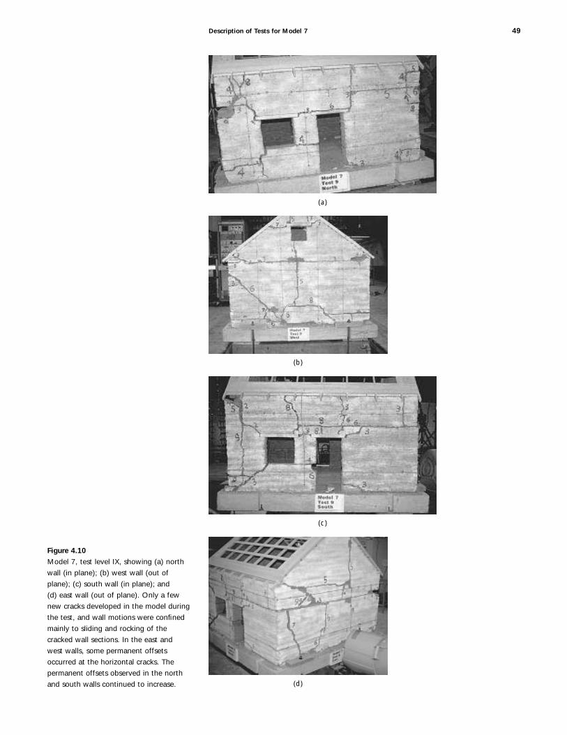
Description of Tests for Model 7 49
Figure 4.10
Model 7, test level IX, showing (a) north
wall (in plane); (b) west wall (out of
plane); (c) south wall (in plane); and
(d) east wall (out of plane). Only a few
new cracks developed in the model during
the test, and wall motions were confined
mainly to sliding and rocking of the
cracked wall sections. In the east and
west walls, some permanent offsets
occurred at the horizontal cracks. The
permanent offsets observed in the north
and south walls continued to increase.
(a)
(b)
(c)
(d)

Instead, the model performed well through test level X. Only a lightlyretrofitted section of the south wall collapsed during the first repetitionof test level X. Table 4.1 is a summary of the model’s performance. Theimportant aspects of the performance of model 7 are as follows:
1. The model behaved very well and generally as expectedbased on test results of the previous six models. Theretrofit system used on this model was clearly a success.
2. The cracking pattern was generally consistent with thatobserved in previous models, but some elements were notexpected. The inclusion of vertical and horizontal straps,with crossties at regular intervals, allowed the retrofitmeasures to behave well even when cracks did not occurwhere they might have been expected.
3. The partial roof diaphragm prevented out-of-plane col-lapse of the gable-end walls. Large displacements occurredat the tops of these walls due to the flexibility of the roofsystem. The roof diaphragm was quite flexible due to thediscontinuity of the diaphragm at the ridge beam.
50 Chapter 4
(a) (b)
(c) (d)
Figure 4.11
Model 7, test level X(1), the first of two
tests at this level, showing (a) north wall
(in plane); (b) west wall (out of plane);
(c) south wall (in plane); and (d) east wall
(out of plane). The dynamic stability of
the structural system is clearly in question
here. Horizontal offset at the attic-floor
level in the east wall is most visible on the
east side of the south wall elevation. The
condition of the north and south walls
continued to degrade. The section of the
wall to the left of each window had off-
sets of approximately 1.88 cm (0.75 in.).
The offsets at the upper west side of the
south wall were largest. Both north and
south walls had offsets of approximately
3.8 cm (1.5 in.) along the diagonal crack
at the lower left corners of the windows.

4. The partial diaphragm at the attic level was considerablystiffer than the roof diaphragm. The through-wall connec-tions performed well. Horizontal cracks developed in thetwo gable-end walls, and the base was able to rock andslide at these locations.
5. Permanent displacements of 2.5–5 cm (1–2 in.) occurredat these horizontal cracks in the walls following testlevels VIII–X. The retrofit system was sufficiently effec-tive to prevent collapse of these walls but not to preventdisplacement.
6. The lower horizontal straps worked effectively to pre-vent the deterioration of the piers under the windows.Diagonal cracks extended from the lower outer cornersof the windows downward to the northeast and southwestcorners, but the straps prevented substantial widening ofthese cracks.
Description of Tests for Model 7 51
(a) (b)
(c) (d)
Figure 4.12
Model 7, test level X(2), the second of
two tests at this level, showing (a) north
wall (in plane); (b) west wall (out of
plane); (c) south wall (in plane); and
(d) east wall (out of plane). Lack of
restraint in the southeast corner allowed
the unstable wall section to collapse at the
end of this test. The retrofit measure on
the north and west walls, where vertical
straps were used, provided sufficient
restraint on the cracked wall sections to
ensure overall structural stability.

52 Chapter 4
Test Maximum Maximum displacementlevel EPGA (g) cm in. Performance summary
I 0.12 2.54 1.00 No damage
II 0.18 5.08 2.00 Minor cracks initiated onnorth, south, and west walls
III 0.23 7.62 3.00 Further development ofcracks; first crack developedin east wall—a horizontalcrack at the attic-floor line
IV 0.28 10.16 4.00 Relatively minor additionalcracks, most in the in-plane(north and south) walls
V 0.32 12.70 5.00 Substantial additional crack-ing; vertical cracks developingin both gable-end walls;minor additional cracks in thein-plane (north and south)walls
VI 0.40 15.88 6.25 Crack pattern nearing fulldevelopment; negligible crackoffsets
VII 0.44 19.05 7.50 Measurable but minor hori-zontal offsets of horizontalcracks at attic-floor line ingable-end walls
VIII 0.48 25.40 10.00 Offsets in the in-plane andout-of-plane walls
IX 0.54 31.75 12.50 Worsening of cracks andspalling of adobe in corners atfloor line and at tops of walls
X(1) 0.58 38.10 15.00 Substantial offsets, particu-larly in east and south walls,which did not have verticalstraps; offsets up to 2.54 cm(1 in.) (model dimensions)
X(2) 0.58 38.10 15.00 Collapse of lower section ofsouth wall
Table 4.1
Model 7: Summary of performance

The tests on models 8 and 9 were designed to continue refinement ofretrofit strategies using the more complex, tapanco-style buildings. Thetests on model 8 were designed to determine whether the strategy usedon model 7 would be successful on a building with thinner walls. Inaddition, the south and west walls of the models would be retrofittedwith vertical center-core rods instead of vertical straps. Model 9 wasunretrofitted to demonstrate how and at what level of shaking anunretrofitted adobe building would fail under the same test conditionsused on models 7 and 8.
Layout of Models 8 and 9
The layout of models 8 and 9 (SL 5 7.5) was the same as that of model 7(SL 5 5) (except that an attic window was added to the east wall) andwas typical of tapanco-style adobe construction. The plans and eleva-tions for these models are shown in figure 5.1. The walls were one wythewide and the bricks were laid in a running bond pattern.
Chapter 5
Description of Tests for Models 8 and 9
Floor joists 3/4 3 2 in.
Attic-floor framing Roof framing
581 /
2 in
.
Ridge beam11/2 3 21/2 in.
Roof rafters5/8 3 1 in.
Figure 5.1
Plan and elevations for models 8 and 9.
47 in
.
17 in
.30
in.
581/2 in.
Elevation of north and south walls Elevation of east and west walls

54 Chapter 5
Construction details are shown in figures 5.2–5.5. In model8, the floor framing and ridge beam were installed before the roof rafterswere in place (fig. 5.2). Figure 5.3 shows model 9 with the complete roofsystem, which represents the basic structural system to which the retrofitmeasures were added in model 8. For construction purposes on thesmall-scale models, much of the retrofit systems for models 7 and 8needed to be installed before the roof was constructed. The roof sheath-ing was widely spaced to ensure that the roof system did not significantlyaffect the out-of-plane motions of the gable-end walls.
Roof-end rafters were placed on both sides of the gable-endwalls so the walls were partially bearing against them (figs. 5.4 and 5.5).Through-bolts were used only on model 8. Even without these through-bolts, the joists did provide some lateral restraint to the tops of the
Figure 5.2
Model 8 before roof framing was added, with ridge beam in place.
Figure 5.3
Model 9 after roof framing was installed.
Figure 5.4
Detail of model 8, with through-bolts
tying roof rafters together on both sides of
the gable-end walls. This retrofit measure
was used only on this model.
Figure 5.5
Blocking between roof rafters screwed to sill plate, used on
models 8 and 9.

gable-end walls in model 9. Because of this restraint, it was important toprovide only minimal horizontal stiffness in the roof system.
The roof rafters were placed on a discontinuous wood topplate that rested on top of the wall. The plate was segmented so as not toact as a bond beam, which would have added strength and stiffness. Intypical historic buildings, the top plate is not continuous along the lengthof the building. Blocking was placed between the rafters at the bearing-wall top plate and at the ridge beam.
Model 8 Retrofit Measures
Model 8 was retrofitted with measures similar to those used on model 7.As in previous models, the retrofit strategy was different on the west andsouth walls than that of the east and north walls (fig. 5.6). The retrofitsystem for model 8 consisted primarily of the following:
1. Partial wood diaphragms on the attic-floor and roof fram-ing, with an exterior, horizontal nylon strap attached tothe attic-floor framing at the floor level.
2. Lower horizontal and vertical straps on each of the northand east walls.
3. Vertical fiberglass center-core rods placed in holes drilledin the south and west walls, rods epoxy-grouted in place,and a lower horizontal strap placed in a center-core holeof the south wall.
Description of Tests for Models 8 and 9 55
Note: Vertical straps on both sides of walls. Lower horizontal straps on both sides of walls. Upper horizontal strap on exterior only.
Fiberglass rods (1/4 in.) anchored into 3/8 in. holes with epoxy. Rods extended from the top of the wall to the concrete slab.
581/2 in.581/2 in.
24 in.
6 in.
8 in.12 in. slope
121/2 in.
421/2 in.
South elevationWest elevation
East elevation North elevation
All walls are 3.1 in. thick
Nylon straps around exterior
Fiberglass rods (1/4 in.) anchored into 3/8 in. holes with epoxy. Rods extended from the top of the wall down 36 in. The center rods were about 6 in. above the concrete slab.
Crosstie locations shown by black dotsVertical nylon straps on
the north and east walls
Nylon straps on both sides of lower wall
Figure 5.6
Elevations showing retrofit measures
applied to model 8.

Details of many aspects of the retrofit system and its installation formodel 8 are shown in figures 5.7–5.15. The connection details werenearly the same as those for model 7 (figs. 4.3–4.5).
Model 8 before the roof diaphragm was added is shown infigure 5.7. Figure 5.8 shows the attic-floor diaphragm at one of the cor-ners. The partial attic-floor diaphragm in model 8 was not as wide asthat used in model 7. In model 8, the floor diaphragm was 11.4 cm(4.5 in.) wide; in model 7 it was 19 cm (7.5 in.). A nylon strap wasadded to ensure transfer of the horizontal loading at the corner of thediaphragm. As demonstrated by the tests, this diaphragm size providedadequate stiffness to control the wall loads and displacements.
The roof framing and partial roof diaphragm are shown infigure 5.9. The roof diaphragm was only 11.4 cm (4.5 in.) wide over thegable ends and 19 cm (7.5 in.) wide over the bearing walls. The discon-tinuity in the diaphragm at the ridge along the gable-end wall allowedlarge displacements at the ridge in model 7. To help control these dis-placements, diagonal sheathing was added at each of the four lower cor-ners of the roof to stiffen the partial diaphragm.
An upper horizontal strap was placed at the attic-floor lineand encircled the perimeter of the building (fig. 5.6). This was attachedto the floor framing, which was connected to the partial floor diaphragm.
On the north and east walls of model 8, the lower horizontalstrap was located on both sides of each section of wall at a level approxi-mately two courses below the bottom of the window. These walls hadfour vertical straps on each wall, again with nylon straps used as cross-ties, as shown for the east wall in figure 5.6.
The south and west walls were retrofitted using measuresdesigned to minimize damage to the wall surfaces. The vertical elementswere fiberglass center-core rods embedded in an epoxy grout at the sameintervals as used for the vertical straps on the north and east walls. Theonly exterior element on the south wall (fig. 5.6) and west wall (fig. 5.10)
56 Chapter 5
Figure 5.7
Model 8 before roof framing was com-
pleted, with ridge beam in place.
Figure 5.8
Partial diaphragm at the southeast corner
of model 8. A nylon strap connected adja-
cent sections of the wood diaphragm.
Figure 5.9
Model 8 after the final retrofit. Diagonal
bracing was added in the corners to stiffen
the partial roof diaphragm.
Figure 5.10
West gable-end wall of model 8 after
retrofit system was completed. The only
sign of the retrofit system on this wall is
the horizontal strap at the attic-floor line.

was a horizontal strap at the attic-floor line. The lower horizontalstrap on the south wall was placedinside a horizontally drilled hole.The west wall had no lower hori-zontal strap at this level because adrill bit of sufficient length wasunavailable. Drilling of the holesand injection of the epoxy groutare shown in figures 5.11 and5.12, respectively. The center-corerods in the west wall terminatedjust short of the wall base becausethe drill bit was not long enoughto reach the slab level. The outsidecenter-core rods extended to about5 cm (2 in.) above the slab level,and the inner center-core rodsextended to approximately12.7 cm (5 in.) above the slab.On the south wall, the center-coreholes were drilled to, but not into,the slab.
Horizontal saw cuts were placed on both sides of the piersadjacent to the windows (fig. 5.13). In model 3, saw cuts were used incombination with center-core rods in an attempt to control crack loca-tions. In that test, the saw cuts were successful in controlling cracks atthese locations. The test on model 3 also showed the favorable structuralperformance of the combination of a horizontal crack with verticalcenter-core elements in controlling the displacement along the cracks.
Small sections of wire mesh were used at a number of cornerlocations throughout the building to provide a wide bearing area for thenylon straps. Wire mesh is flexible and ductile, and it distributes the loadover a wide enough area to prevent the strap from digging into the adobewall (figs. 5.14 and 5.15).
Description of Tests for Models 8 and 9 57
Figure 5.11
Center-core holes being drilled in the west
gable-end wall.
Figure 5.12
Epoxy resin grout being injected into
model. This measure was used to attain
continuity between the center-core rods
and the adobe wall.
Figure 5.13
Piers on either side of the windows, show-
ing horizontal cuts made to encourage
horizontal cracks at these locations.
Figure 5.14
West gable-end wall of model 8, showing
wire mesh used for bearing load distribu-
tion under vertical straps at the top of the
walls.
Figure 5.15
Wire mesh used under upper horizontal
straps at the building corners.

Instead of the nylon cord used in model 7, the crossties usedin model 8 were commercial nylon cable ties that are easily installed andtightened. Larger cable ties and an automatic tensioning tool could beused in the field. They worked successfully during the tests on model 8.Cable ties were closely spaced above and below the attic floor line to tryto control the magnitude of the crack offsets along horizontal cracks thatwere likely to occur near the floor line.
Test Results for Model 8
The retrofit system for model 8 was designed, in part, to control perma-nent wall offsets and difficult-to-repair damage. All walls behaved wellduring the entire test sequence. In the areas where center-core rods wereplaced, damage was very limited. In other areas, significant offsetsoccurred and gaps opened between cracked wall sections, but the over-all structure was stable during all tests. Although the walls of model 8 (SL 5 7.5) were thinner than those of model 7 (SL 5 5), the gable-endwalls performed very well. There was a somewhat greater displacementcontrol provided by the horizontal straps due to the closer spacing of thecrossties and the use of wire mesh. Where mesh was used, straps wereprevented from digging into the walls, which would have allowed thestraps to loosen and permit larger displacements.
The most surprising result observed was the effectiveness ofthe epoxy-anchored, center-core rods, which acted as effective reinforcingelements. Visible cracks in walls retrofitted in this way were delayed untilmuch later in the testing sequence than observed in other models (see fol-lowing sections).
A summary of the important aspects of the results of the testsequence for model 8 is listed in table 5.1. Photographs of model 8 aftereach test, starting with test level III, are shown in figures 5.16–5.24.
Flexural Test of a Wall Element with Center-Core Reinforcement
After test level X was completed, examination of the west wall wasundertaken in an attempt to understand more about the effectiveness ofthe center-core rods. When the adobe material was broken away fromaround one of the rods (fig. 5.25), the uneven surface that the epoxyformed at the adobe interface was evident. This uneven surface wasindicative of the nature of the bonding of the epoxy resin and the fiber-glass rod to the adobe wall, with the result that the composite structureacted effectively as a reinforcing rod. It should be noted that there wasa small yet visible crack in the adobe at the time the section of wallwas removed from the building. In concrete, reinforcing bars do notbecome effective in tension or flexure until the concrete has cracked.These cracks can be very small and not even visible to the naked eye.Therefore, even though the section of adobe wall was cracked, it didnot affect the strength of this “reinforced adobe beam.”
58 Chapter 5

The section of the west wall was removed from the modeland then statically loaded at mid-span with lead blocks until failureoccurred (fig. 5.26). A videotape made during the tests showed that theadobe material was crushed when the beam failed. The load at failurewas approximately 72.6 kg (160 lb.). Based on calculations similar tothose used for analyzing concrete, the capacity of this beam was approxi-mately 124 N-m (1100 in.-lb.). The moment induced by the loading wasapproximately 136 N-m (1200 in.-lb.). These calculations demonstratean accurate analytical method for determining the strengthening effectsof the fiberglass bars embedded in the adobe wall of the model building.
Test Results for Model 9
Model 9 was an unretrofitted, tapanco-style control model similar tomodel 8. The results of the sequence of tests on model 9 demonstrated
Description of Tests for Models 8 and 9 59
Test Maximum Maximum displacementlevel EPGA (g) cm in. Performance summary
I 0.12 2.54 1.00 No damage
II 0.18 5.08 2.00 Very minor cracks in west gable-end wall below window
III 0.23 7.62 3.00 Minor cracking in east wall near window; no cracks in west wall; crack develop-ment in north wall at openings; only one minor crack formed in the south wall
IV 0.28 10.16 4.00 Development of vertical cracks in both out-of-plane walls with some cracking atthe base; development of additional cracks, typical at this stage of the testingsequence, in north (in-plane) wall; only damage to the south wall: vertical crackcaused by tensile stresses from pullout of the west wall
V 0.32 12.70 5.00 Development of diagonal yield-line cracks in out-of-plane walls; no significantnew cracks in the in-plane walls, though significant cracks already present innorth wall; no damage in south wall except existing vertical crack near thewest wall
VI 0.40 15.88 6.25 No new cracks observed in south wall; some additional horizontal cracks formedin the already badly damaged north wall; development of additional cracks inout-of-plane walls: some horizontal cracks in east wall and cracks around the twomain panels reinforced with center-core rods in west wall
VII 0.44 19.05 7.50 Still no new cracks in the nearly undamaged south wall; a few additional cracksformed in the severely cracked north wall although with no significant offsets;minor additional cracks in the east and west out-of-plane walls
VIII 0.48 25.40 10.00 Appearance of some cracks in south wall, however, main panels in the wall withcenter-core rods still not cracked; offsets of 0.6 cm (0.25 in.) at three locations innorth wall; offsets of approximately 0.6 cm (0.25 in.) in east wall (straps); no off-sets observed in west wall (center-core rods)
IX(1) 0.54 31.75 12.50 Retrofit system very effective, although offsets beginning to grow larger at mostlocations; offsets in north and east walls (straps) increased by about 0.3 cm (0.13 in.); offsets in west wall (center-core rods) minimal except at base belowcenter cores; still only minimal damage to south wall except for mid-height blockat corner, showing offset of approximately 0.95 cm (0.38 in.)
IX(2) 0.54 31.75 12.50 Main areas of offsets growing in each wall, although building continuing to per-form well; development of horizontal crack in north block in west wall (center-core rods) but because of reinforcing effects of center cores, crack remains small
X 0.58 38.10 15.00 Model performing well, with offsets in each wall increasing up to 2.5 cm (1 in.);sections of wall below ends of center-core rods in west wall dislodged
Table 5.1
Model 8: Summary of performance (displacements and accelerations in prototype dimensions)

60 Chapter 5
(a)
(b)
(c)
(d)
Figure 5.16
Model 8, test level III, showing (a) east
wall (out of plane); (b) north wall (in
plane); (c) west wall (out of plane); and
(d) south wall (in plane). A few minor
cracks were found during test levels II and
III. More cracks were observed in the north
(in-plane) wall than in the out-of-plane
walls. In the north wall, cracks developed
at the upper corners of the door and win-
dow. The only crack in the south (in-plane)
wall was in the upper corner near the west
wall. In the out-of-plane direction, the
west and east walls suffered little damage.
The west wall had a small vertical crack
above and below the window. No damage
was observed in the east wall.

Description of Tests for Models 8 and 9 61
(a)
(b)
(c)
(d)
Figure 5.17
Model 8, test level IV, showing (a) east
wall (out of plane); (b) north wall (in
plane); (c) west wall (out of plane); and
(d) south wall (in plane). In the out-of-
plane direction, both the east and west
walls developed vertical cracks near the
center of the wall, and both had some
horizontal crack damage near the base.
The out-of-plane walls acted as plates
with vertical yield lines at mid-span. In the
in-plane direction, the north wall (straps)
developed a more complete crack pattern
that included a horizontal crack in the
west side near the top of the wall and a
vertical crack at the west end. The south
wall (center cores) had a vertical crack at
the west end caused by lateral movements
of the west gable-end wall.

62 Chapter 5
(a)
(b)
(c)
(d)
Figure 5.18
Model 8, test level V, showing (a) east
wall (out of plane); (b) north wall (in
plane); (c) west wall (out of plane); and
(d) south wall (in plane). The in-plane
walls sustained little additional damage.
Minor cracks developed in the north wall,
and no cracks appeared in the south wall.
The out-of-plane walls developed consid-
erably more cracks. The location of the
cracks followed typical yield-line patterns.
Each wall developed a diagonal crack from
the upper corner on one side, extending
to the center of the base of the wall. The
east wall developed an additional, nearly
vertical crack near the south end.

Description of Tests for Models 8 and 9 63
(a)
(b)
(c)
(d)
Figure 5.19
Model 8, test level VI, showing (a) east
wall (out of plane); (b) north wall (in
plane); (c) west wall (out of plane); and
(d) south wall (in plane). Crack patterns
continued to develop in the east and west
walls. The west wall sustained additional
diagonal cracking at the northern end
and a horizontal crack near the center,
located at about the level of the end of
the center-core rods. The two rods near
the center of the wall did not extend to
the slab. In the in-plane walls, there were
no additional cracks in the south wall, but
further cracks appeared in the north wall.
The basic crack pattern in each wall was
nearly complete except for the lack of
damage to the south wall.

64 Chapter 5
(a)
(b)
(c)
(d)
Figure 5.20
Model 8, test level VII, showing (a) east
wall (out of plane); (b) north wall (in
plane); (c) west wall (out of plane); and
(d) south wall (in plane). At this point, the
building walls had cracked into major sec-
tions that allowed them to move dynami-
cally without sustaining substantial
additional damage. Minor fragmentation
of the wall continued in the north and
west walls (straps), and little additional
damage developed in the west wall (cen-
ter core). The center cores in the south
wall continued to provide adequate rein-
forcement that prevented cracks from
occurring.

Description of Tests for Models 8 and 9 65
(a)
(b)
(c)
(d)
Figure 5.21
Model 8, test level VIII, showing (a) east
wall (out of plane); (b) north wall (in
plane); (c) west wall (out of plane); and
(d) south wall (in plane). Several cracks
finally developed in the south wall of this
model, including a vertical crack at the
door and a horizontal crack at the base
of the wall below the window. The cracks
that had developed in the other three
walls remained fairly stable, although
offsets of about 0.6 cm (0.25 in.) were
observed in the north and east walls.

66 Chapter 5
(a)
(b)
(c)
(d)
Figure 5.22
Model 8, test level IX(1), the first of two
tests at this level, showing (a) east wall
(out of plane); (b) north wall (in plane);
(c) west wall (out of plane); and (d) south
wall (in plane). Crack patterns changed
little, but the substantial amount of addi-
tional spalling at crack edges and corners
was indicative of the large motions to
which the building was subjected during
this test. The center cores in the west wall
allowed the formation of major blocks
with two center-core rods in each block.
Damage to the south wall (with center
cores) increased but was considerably
less than that observed in the north wall
(with straps).

Description of Tests for Models 8 and 9 67
(a)
(b)
(c)
(d)
Figure 5.23
Model 8, test level IX(2), the second of
two tests at this level, showing (a) east
wall (out of plane); (b) north wall (in
plane); (c) west wall (out of plane); and
(d) south wall (in plane). Offsets at exist-
ing cracks increased to about 1.25 cm
(0.5 in.). Damage to the basic panels in
the south wall was still negligible. The
walls were beginning to slide at the foun-
dation level.

68 Chapter 5
(a)
(b)
(c)
(d)
Figure 5.24
Model 8, test level X, showing (a) east
wall (out of plane); (b) north wall (in
plane); (c) west wall (out of plane); and
(d) south wall (in plane). Crack pattern
remained fundamentally the same, and
no new cracks were created. The center-
core rods prevented major damage from
occurring in the walls in which they were
installed. For the most part, cracks formed
in the area just outside of the center-core
rods. There were no rods or straps in the
section at the west end of the south wall,
which permitted an offset of more than
1.25 cm (0.5 in.) at that location. The off-
sets in the east and north walls increased
to about 1.8 cm (0.7 in.). The straps did
an effective job of maintaining stability
but were less effective than center-core
rods at controlling damage.

the fragility of an unretrofitted adobe building. Cracks began during testlevels II and III and continued to develop during test level IV. The dyna-mic motions of the gable-end wall became apparent during test level IV,and the model nearly collapsed during test level V. The roof rafters onboth sides of the gable-end walls provided some resistance to the motionof these walls and probably were responsible for the stabilization of themodel during test level V (fig. 5.27).
Both gable-end walls collapsed during test level VI (fig. 5.28).The collapse of the east wall was more complete because the upper sec-tion of the wall collapsed inward and, simultaneously, the lower sectionof the wall collapsed outward. The west wall collapse was incomplete.The difference in the behavior between the two walls can be attributedto the crack patterns that developed during earlier tests. There were twohorizontal cracks in the east wall, and both the upper and lower sections
Description of Tests for Models 8 and 9 69
Figure 5.25
Close-up of center-core rod epoxy after
removal of adobe.
Figure 5.26
Section of wall panel containing center-
core rod before static-loading test.

of this wall collapsed. In the west wall, there was only a single horizon-tal crack located at a height lower than the upper horizontal crack inthe west wall.
Damage to the in-plane walls was typical of that observedduring previous testing. Offsets in these walls were small during all ofthe tests because the table motions were not strong enough to lead tosignificant in-plane damage. In previous research performed at Stanford,significant in-plane damage did not occur until test level VII, thus theperformance of model 9 was consistent with past observations.
Summary of Test Results for Models 8 and 9
Tests on models 8 and 9 showed the dramatic effects that can result fromimplementing a complete, stability-based retrofit system. The perfor-mance of these models was consistent with results from the previousGSAP tests and contributed to the refining of the stability-based reinforc-ing techniques.
The primary goal of retrofit measures is to prevent collapse,and that goal was effectively accomplished by the system installed onmodel 8. A secondary goal was to minimize the extent of damage duringmoderate to large ground motions. The strapping method was slightlymore effective at limiting permanent displacements than similar methods
70 Chapter 5
(a) (b)
(c) (d)
Figure 5.27
Model 9, test level V, showing (a) east
wall (out of plane); (b) north wall (in
plane); (c) west wall (out of plane); and
(d) south wall (in plane). The dynamic
motion of the gable-end walls increased
substantially, and the model became
nearly unstable. The slight resistance pro-
vided by the roof framing may have pre-
vented out-of-plane collapse of the
gable-end walls. A permanent offset of
approximately 1.9 cm (0.75 in.) perpen-
dicular to the plane of the wall occurred
at the center of the upper horizontal crack
in the east wall. A few additional cracks
developed near the base of the east wall,
and the vertical cracks in the west wall
continued to extend downward.

used on model 7. This difference can be attributed to the use of moreclosely spaced crossties and the addition of wire mesh at some locationsto distribute the loading at corners under the nylon straps, which helpedprevent the straps from digging into the adobe.
As mentioned, the performance of the walls that had beenretrofitted with fiberglass center-core rods embedded in an epoxy groutwas unexpectedly good. These walls—south (in plane) and west (out ofplane)—suffered very little damage during the tests. During placementof the center-core rods, the epoxy grout was absorbed unevenly into theadobe and permitted the rods to bond effectively to the adobe material.
In summary, the important aspects of the performance ofmodels 8 and 9 are as follows:
1. Model 9, the control model, collapsed during test levelVI. In the prototype domain, the peak acceleration wasapproximately 0.4 g and the peak displacement was19 cm (7.5 in.). The model nearly collapsed during theprevious test.
2. The retrofit systems installed on model 8 were effective inpreventing collapse of this building.
3. Vertical straps can limit the damage during very strongground motions but have little effect on limiting crackdevelopment during moderate ground motions.
Description of Tests for Models 8 and 9 71
(a) (b)
(c) (d)
Figure 5.28
Model 9, test level VI, showing (a) east
wall (out of plane); (b) north wall (in
plane); (c) west wall (out of plane); and
(d) south wall (in plane). Large sections of
both gable-end walls collapsed. The upper
section of the east wall collapsed inward
at the beginning of the test, followed by
the collapse of the lower section of that
wall. In the latter part of the test, the
upper section of the west gable-end wall
also collapsed. The conditions of the in-
plane walls did not worsen significantly
during this test. The missing section at the
east end of the south wall was attached to
the section of the east wall that collapsed
out of plane.

4. Center-core reinforcement can reduce damage during bothmoderate and large ground motions. The rods used inmodel 8 acted as reinforcing bars and were effective instrengthening the adobe walls.
5. The diagonal braces at the corners of the partial roofdiaphragm in model 8 were effective in increasing thestiffness of the roof system over that of the roof ofmodel 7. This roof system was designed for use in thesetest model buildings, however, and a similar system isunlikely to be used in a full-scale building. An existingroof will be completely sheathed with boards or plywood,which is likely to provide sufficient rigidity.
6. The saw cuts in the south wall were successful in thatcracks occurred at these locations rather than radially atstress-concentration locations at the window corners.Horizontal cracks are easier to manage than cracks thatare diagonally oriented.
72 Chapter 5

The analysis and synthesis of the most important aspects of GSAP
research on small-scale models are presented in this chapter. In theresearch program, tests were conducted on six simple models and threetapanco-style models that included roof and floor framing.
The first section of this chapter contains a discussion of(1) the important dynamic characteristics of the model buildings, (2) thelevel of damage that can be expected during different levels of groundacceleration, and (3) the effectiveness of the various retrofit measures onthe building systems.
A brief summary of results of observations of damage to his-toric adobe buildings made after the January 17, 1994, Northridge earth-quake is presented in the second section.
The final section is a synthesis of the results from both themodel tests and field observations. In general, there is good correlationbetween damage observed in the laboratory and that observed in thefield. This agreement is important for those assessing damage from pastearthquakes, determining the risk of damage in the future, and designingseismic retrofits for existing historic adobe buildings.
Analysis of Model Test Results
Initial crack development (test levels II–IV)Crack initiation began during early tests at EPGA values of 0.18 g to0.28 g. Typically, cracks began during test level III and increased somewhatduring test level IV, but full crack development did not occur until testlevels V and VI. There were some clear indications of differences in crackdevelopment that were functions of the slenderness ratios of the walls.
Effect of slenderness ratios on out-of-plane performanceThe test level required to cause damage to out-of-plane walls was one ofthe greatest differences in the performance of thick and thin walls (fig.6.1). Thin walls (SL 5 11) are shown in figure 6.1a, b, and thick walls (SL 5 5) are shown in figure 6.1c, d. As would be expected from an elasticanalysis, the crack pattern in the out-of-plane walls (fig. 6.1a) occurredfirst, followed by cracking in the in-plane walls. Once cracks had devel-oped in the out-of-plane walls, the loads were quickly transferred to the
Chapter 6
Analysis of Test Results for Models 1–9

in-plane walls through the attached bond beam, causing cracks in the in-plane walls (fig. 6.1b).
In contrast, the out-of-plane thick walls (SL 5 5) sufferedvery little damage during test level IV, while the in-plane walls sufferedcracking at the corners of some of the openings (fig. 6.1c, d). The thickwalls had much greater flexural stiffness and strength than the thinnerwalls and were mostly able to resist the loading with only a minor crackat the bottom of the window opening. The out-of-plane thick walls werestrong enough to resist the loading and were sufficiently stiff to transferthe load to the in-plane walls, which suffered damage similar to thatof the thin walls. As would be expected from an elastic analysis, the thinwalls (SL 5 11) were much more susceptible to out-of-plane damage thanthe thick walls (SL 5 5). There was little difference in the initial crackpatterns of the in-plane walls.
Effect of slenderness ratios on in-plane performanceIn general, the level of damage to the in-plane walls was independent ofwall thickness. A comparison of in-plane wall damage after test level VIIfor walls with differing slenderness ratios (SL 5 5, 7.5, and 11) is shownin figure 6.2. Damage was similar for each of these walls. The principaldamage occurred at the corners of the doors and windows and at the topand bottom of the pier between the door and the window, which wastypical of both laboratory and field observations.
74 Chapter 6
(a) (b)
(c) (d)
Figure 6.1
Comparison of crack initiation after test
level IV for thin-walled model 6 (SL 5 11),
showing (a) west wall, and (b) south wall;
and thick-walled model 4 (SL 5 5), show-
ing (c) east wall and (d) north wall.

The performance of the walls with epoxied center-core ele-ments was the exception to this observation. The epoxied rods acted aseffective reinforcements and delayed the appearance of crack damage.Damage to the walls of model 8 (fig. 5.19) and to the walls with epoxiedcenter cores was very slight compared to the full crack development ofthe walls fitted with vertical straps.
Similarities and variations in crack patternsThe crack patterns of corresponding walls were often consistent fromone model to the next and in opposite walls of the same building.Nevertheless, there was one difference between similar walls that weresubjected to the same input motions. The four walls shown in figure 6.3were all thin walls (SL 5 11). The retrofit measures had a negligible effecton their elastic performance, and the resulting crack patterns had manysimilarities. The principal motion of the walls was out-of-plane rockingof the center panel, as shown in the whitened area in figure 6.4. In figure6.3a–c, the crack pattern is nearly the same. This pattern is defined by acrack in the upper left corner of the wall that extends diagonally to thebase of the door. From the right side, the crack starts at the upper rightcorner of the wall and extends through the window opening. However,in figure 6.3d, no major diagonal crack in the large left-hand panel isobserved, suggesting that variability in material and construction typi-cally exists in adobe structures, which could account for the difference.
Analysis of Tests Results for Models 1–9 75
(a) (b)
(c)
Figure 6.2
Comparison of damage of in-plane walls
with differing slenderness ratios during
test level VII: (a) model 4 (SL 5 5), north
wall; (b) model 1 (SL 5 7.5), north wall;
and (c) model 6 (SL 5 11), south wall.
Similar damage was typically observed in
all in-plane walls at this test level.

Effect of slenderness ratio on the dynamic performance of walls with bond beamsThe dynamic out-of-plane motion of the thin walls (SL 5 11) that had awood bond beam was significantly different from that observed in themoderate and thick walls (SL 5 7.5 and 5). The thin walls (SL 5 11)
76 Chapter 6
(a) (b)
(c) (d)
Figure 6.3
Comparison of crack patterns in out-of-
plane walls with the same slenderness
ratio (SL 5 11) after test level IV:
(a) model 5, west wall; (b) model 6,
east wall; (c) model 6, west wall; and
(d) model 5, east wall.
Figure 6.4
Cracked wall section of model 6, showing
pattern typical of a section of wall sub-
jected to out-of-plane rocking about
its base.

easily rocked about their bases, and the principal lateral support wasprovided by the bond beam whose stiffness and tributary mass definedthe dynamic characteristics of the walls. This behavior was not observedin the walls of moderate thickness (SL 5 7.5) with the same bond beam;the thickness of the wall did not permit easy rocking about the base,which significantly affected the dynamic motion of the walls. The out-of-plane motion at the tops of the walls was not amplified as it was in thethinner walls. This effect is difficult to observe using static images, butfigure 6.5a, b shows damage indicative of this behavior. In these pho-tographs, spalling of the adobe at the tops of the walls can be seen at thepoints of anchorage between the bond beam and the wall. This spallingis an indication of the large load transfer required for the bond beam tostabilize the walls. The thicker walls (SL 5 7.5), shown in figure 6.5c, d,did not have the same type of amplified motion, and spalling did notoccur at the anchor bolts at the tops of the walls. The greater wall thick-ness also reduced the likelihood of spalling. This behavior is clearly evi-dent in the videotaped recording of these tests.
Performance during moderate to strong seismic levels (test levels V–VII)
Complete crack developmentComplete crack development typically occurred during test levels V, VI,and VII with EPGA values of 0.32 g, 0.40 g, and 0.44 g, respectively.
Analysis of Tests Results for Models 1–9 77
(a) (b)
(c) (d)
Figure 6.5
Comparison of damage after test level VII,
indicative of the rocking motion of the
out-of–plane walls for the thinner-walled
building with bond beams, such as model 6
(SL 511): (a) west wall and (b) east wall.
Damage along the tops of thinner walls is
indicative of the amplifying effect of the
bond beam. Similar behavior was not
observed in the thicker walls of model 2
(SL 5 7.5): (c), west wall and (d) east wall.
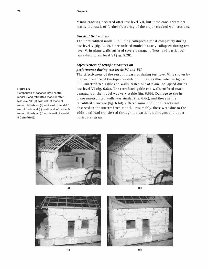
Minor cracking occurred after test level VII, but these cracks were pri-marily the result of further fracturing of the major cracked wall sections.
Unretrofitted modelsThe unretrofitted model 5 building collapsed almost completely duringtest level V (fig. 3.10). Unretrofitted model 9 nearly collapsed during testlevel V. In-plane walls suffered severe damage, offsets, and partial col-lapse during test level VI (fig. 5.28).
Effectiveness of retrofit measures on performance during test levels VI and VIIThe effectiveness of the retrofit measures during test level VI is shown bythe performance of the tapanco-style buildings, as illustrated in figure6.6. Unretrofitted gable-end walls, tested out of plane, collapsed duringtest level VI (fig. 6.6a). The retrofitted gable-end walls suffered crackdamage, but the model was very stable (fig. 6.6b). Damage to the in-plane unretrofitted walls was similar (fig. 6.6c), and those in theretrofitted structure (fig. 6.6d) suffered some additional cracks notobserved in the unretrofitted model. Presumably, these were due to theadditional load transferred through the partial diaphragms and upperhorizontal straps.
78 Chapter 6
(a) (b)
(c) (d)
Figure 6.6
Comparison of tapanco-style control
model 9 and retrofitted model 8 after
test level VI: (a) east wall of model 9
(unretrofitted) vs. (b) east wall of model 8
(retrofitted); and (c) north wall of model 9
(unretrofitted) vs. (d) north wall of model
8 (retrofitted).

Performance during very strong seismic levels (test levels VIII–X)Test levels VIII, IX, and X, with EPGA levels of 0.48 g, 0.54 g, and0.58 g, respectively, were challenging for the model buildings. Theeffectiveness of a retrofit was demonstrated by successful performanceduring these three tests. The lighter retrofit measures failed during oneof these tests, while the more robust and resilient retrofit solutions per-formed well after several repetitions of test level X.
Comparison of retrofit measures during test levels VII and VIIIThe light retrofit system used on the thin south and west walls of model6, which included a bond beam and vertical local ties, was adequate towithstand the motions of test level VII, but the out-of-plane wall col-lapsed during test level VIII (fig. 6.7a). By comparison, the opposite wallsof the same model were stable during this test (fig. 6.7b), a result thatcan be attributed to the effectiveness of the vertical straps. Similarly,moderately thick walls with a bond beam and center-core rods alsobehaved well during test level VIII (fig. 6.7c).
Comparison of retrofit measures during test level IXTest level IX was even more of a challenge to some of the lightly retro-fitted model buildings. A large section of the in-plane thin wall withbond beam and local ties collapsed during this test (fig. 6.8a). Again, the
Analysis of Tests Results for Models 1–9 79
(a) (b)
(c)
Figure 6.7
Comparison of out-of-plane performance
after test level VIII of (a) lightly retrofitted
walls (model 6, west wall) vs. (b) more
complete retrofits that included vertical
straps (model 6, east wall) or (c) center
cores (model 2, east wall).

80 Chapter 6
(a) (b)
(c)
Figure 6.8
Comparison of in-plane performance after
test level IX of (a) lightly retrofitted mod-
els (model 6, south wall) vs. (b) more
complete retrofits that included vertical
straps (model 6, north wall) or (c) center
cores (model 2, north wall).
light retrofit system used on this thin wall (SL 5 11) was not adequate toprovide sufficient resilience to withstand the demands of this majordynamic event.
The addition of vertical straps instead of local ties improvedthe performance of the thin walls. The condition of the thin wall with abond beam and vertical straps after test level IX is shown in figure 6.8b;the cracked wall is still stable and generally in good condition. The con-dition of the two in-plane walls shows the difference between the use oflocal ties (fig 6.8a) and the use of vertical straps (fig. 6.8b). Good behav-ior was also observed in the moderate walls with a bond beam and cen-ter cores during test level IX (fig. 6.8c).
Increased effectiveness of bond beams when combined with vertical straps or center coresThe behavior of the model buildings with bond beams and little addi-tional retrofitting demonstrated the inadequate resistance of a bondbeam when used without other retrofit measures. In the previousStanford testing (Tolles and Krawinkler 1989), one model (SL 5 7.5) wasretrofitted with only a wood bond beam. While the beam was more thansufficient to transmit the loading from the out-of-plane walls to the in-plane walls, the bond beam alone was not sufficient to restrain themovements of the cracked block sections of the walls. Relative displace-

ments along cracks accumulated as the tests progressed, and collapseoccurred. The model with the bond beam collapsed at the end of testlevel VIII. In the GSAP research discussed here, the light retrofit systemusing a bond beam and local ties (SL 5 11) behaved similarly to themodel with only a bond beam; the out-of-plane wall collapsed duringtest level VIII, and the in-plane wall collapsed during test level IX.
Model behavior as a function of wall slenderness and retrofit measuresThe behavior of the model buildings during the most extreme tests wasa function of both the thickness of the walls and the type of retrofitmeasures installed. With very thick walls (SL 5 5), only minimal retrofitmeasures were needed to prevent instability. All four thick walls withhorizontal straps survived, with only the addition of local ties to preventinstability of the pier between the door and window openings. The out-of-plane east wall, however, was nearly unstable after test level X (fig.6.9a). Walls of moderate thickness (SL 5 7.5), when retrofitted with thesame horizontal straps, survived test level IX but collapsed during testlevel X (fig. 6.9b). This collapse may have been prevented by additionalthrough-wall ties along the length of the upper horizontal straps. Theperformance of these walls indicates that additional vertical elementsmay be necessary for the survival of moderate to thin walls during theseverest ground motions.
Analysis of Tests Results for Models 1–9 81
(a) (b)
(c) (d)
Figure 6.9
Comparison of out-of-plane wall perfor-
mance in lightly retrofitted models after
partial collapse: (a) model 4 (SL 5 5), east
wall, test level X; (b) model 1 (SL 5 7.5),
east wall, test level X; (c) model 6
(SL 5 11), west wall, test level VIII; and
(d) model 6 (SL 5 11), east wall, test
level X.

The performance of a thin wall with a bond beam and localties showed that modest improvements to the retrofit systems on a thin-walled building still may not be sufficient. The out-of-plane walls col-lapsed during test levels VIII and IX, respectively (fig. 6.9c, d). Thesetwo walls had a bond beam, lower horizontal straps, and local ties incritical locations.
The other two walls of the same model behaved considerablybetter with the addition of vertical straps. Nevertheless, during test levelX, the out-of-plane east wall lost the pier between the door and windoweven with the vertical strap (fig. 6.9d). This type of damage was notobserved in other buildings with thicker walls when vertical straps orcenter-core rods were installed.
Effectiveness of a complete retrofit system demonstrated by the performance of tapanco-style models 7–9The performance of the tapanco-style models 7–9 demonstrated convinc-ingly the effectiveness of the installed retrofit systems. Figures 6.10 and6.11 show the behavior difference of out-of-plane and in-plane walls,respectively, of the retrofitted models after the final test. As noted earlier,the unretrofitted model 9 (fig. 6.6a) collapsed near the beginning of testlevel VI. The performance of the retrofitted models 7 and 8 that survivedtest level X was, therefore, extremely successful by comparison.
82 Chapter 6
(a) (b)
(c) (d)
Figure 6.10
Comparison of the out-of-plane wall per-
formance of tapanco-style models with
differing retrofit systems after test level X:
(a) model 7, east wall; (b) model 7, west
wall; (c) model 8, east wall; and (d) model
8, west wall.

Comparison of out-of-plane, gable-end wallsThe gable-end walls of the tapanco-style models were all tested out ofplane. In addition to the partial diaphragms on each building, the mini-mum retrofits were upper and lower horizontal straps. The only gable-end wall that did not have lower horizontal straps was the west wall ofmodel 8 (fig. 6.10d), which had center-core rods. In model 7, the eastwall (fig. 6.10a) had only upper and lower straps, yet the thick walls(SL 5 5) remained stable. There was an approximately 3.8 cm (1.5 in.)offset at the mid-height horizontal crack, because there was littlerestraint across this crack plane.
Vertical straps provided additional restraint that minimizedthe extent of dynamic and permanent crack offsets. In model 7, the per-formance of the west wall (fig. 6.10b) was somewhat better than that ofthe east wall as a result of the vertical straps that provided restraint forblock movements along horizontal and diagonal cracks.
Effect of more closely spaced crossties in tapanco-style modelsThe retrofit system used on model 8 (SL 5 7.5) was modified slightly totry to decrease the amount of offset at horizontal cracks. The east wall(fig. 6.10c) had vertical straps, and the wall crossties were spaced closelytogether to limit the relative displacement between adjacent blocks.The displacements in the gable-end wall were limited to 1.25–1.9 cm(0.5–0.75 in.) in the model domain, which was an improvement over the
Analysis of Tests Results for Models 1–9 83
(a) (b)
(c) (d)
Figure 6.11
Comparison of the in-plane wall perfor-
mance of tapanco-style models with dif-
fering retrofit systems after test level X:
(a) model 7, south wall; (b) model 7, north
wall; (c) model 8, north wall; (d) model 8,
south wall.

performance of model 7 but was not as dramatic as that achieved by theinstallation of center-core rods.
Effect of center-core rods in tapanco-style modelsThe performance of the west wall of model 8 showed the extent to whichcenter-core rods can reduce the offset across cracks during out-of-planeground motions (fig. 6.10d). This wall had center-core rods that extendedfrom the top to almost the base of the wall. Most of this wall wasretrofitted with epoxied center-core rods and sustained minimal crackdamage. There were no measurable offsets across center-core rods.Extensive damage to this wall occurred near the base in the area wherethe center-core rods did not extend. Most of the energy was dissipatedin the areas outside of the center-core rods. If the center-core rods hadextended into the foundation, there may have been additional damage inthe upper part of the wall since there would have been no clear area forenergy dissipation.
In the in-plane direction, center-core rods were also mosteffective at preventing permanent offsets. Figures 6.10 and 6.11 show thedamage to the retrofitted tapanco-style models at the end of the testingsequence. In general, the cracks opened to approximately 1.9 cm (0.75 in.)in each of the walls except where epoxied center-core rods were installed.The horizontal straps restrained the development of permanent offsetsin the walls but still allowed displacements of the blocks. Stiffer strapsmay have been used to provide greater restraint against damage, but twofactors would need to be taken into account: (1) a failure plane mightdevelop just above the strap that would permit slippage, or (2) the strapmay dig into the adobe material and loosen, even with a stiffer strap. Totry to control the latter, a wire-mesh screen was added at the exposedcorners. The straps were still able to dig into the adobe at the through-wall holes. Minimal damage was observed in the in-plane wall of model9, where the vertical center-core rods were used (fig. 6.11d).
Summary of performance of model buildingsThe retrofit measures used on in-plane and out-of-plane walls and theresults of the final tests on models 1–9 are summarized in tables 6.1and 6.2.
Initial cracking and moderate damageTypically, cracks were initiated during test level III or IV at EPGA valuesof 0.23 g and 0.28 g, respectively. Cracks continued to develop duringtest levels V and VI; after these tests, the principal cracked block sectionswere observed to have developed. The full development of the crackedblock sections then determined the nature of seismic performance duringthe succeeding tests (test levels VII and higher).
Severe damage and collapseUnretrofitted models collapsed during test level V or VI. These levels had EPGA values of 0.32 to 0.40 g, respectively, and, more important,the peak displacements were approximately 15.2–17.8 cm (6–7 in.) in the
84 Chapter 6

Analysis of Tests Results for Models 1–9 85
Model no. Collapse Principal retrofit and wallsa level measures Comments
5 VII None (control model) Complete collapse
4 NE No collapse Upper horizontal strap Basically stable with substantial block offsets
1 NE X Upper horizontal strap Out-of-plane collapse that may have been prevented bymore closely spaced crossties
4 SW No collapse Upper and lower horizontal straps Basically stable with substantial block offsets
1 SW No collapse Upper and lower horizontal straps Close to collapse during final test
6 SW VIII Bond beam, lower horizontal straps, Collapse of out-of-plane west wall during test level VIII; and local ties at piers between collapse of most of south wall during test level IXthe door and windows
6 NE No collapse Bond beam, lower horizontal straps, Out-of-plane walls near collapse; center pier dislodgedand vertical straps
2 NE No collapse Bond beam and center-core rods Stable behavior in all tests
2 SW No collapse Bond beam, lower internal horizontal Stable behavior in all testsstraps, and vertical straps
3 NE No collapse Bond beam, lower internal horizontal Stable behavior in all testsstraps, and vertical center-core rods
3 SW No collapse Bond beam, lower internal horizontal Stable behavior in all testsstraps, and vertical center-core rods
Table 6.1
Models 1–6: Summary of results for wall pairs
Model no. Collapse Principal retrofit and wallsa level measures Comments
9 VI None (control model) Complete collapse of gable-end walls
8 NE No collapse Partial wood diaphragms—upper strap Stable behavior in all testsat attic-floor level, lower straps, and vertical straps
8 SW No collapse Partial wood diaphragms—upper strap Stable behavior in all testsat attic-floor level, lower straps, and vertical center-core rods; no lower strap on west wall
7 NE No collapse Partial wood diaphragms—upper strap Stable behavior in all testsat attic-floor level, lower straps, and vertical straps
7 SW X Partial wood diaphragms—upper strap Partial collapse of south (in-plane) wall during test level Xat attic-floor level and lower straps; no vertical straps
Table 6.2
Models 7–9: Summary of results for wall pairs
aNE 5 north and east walls; SW 5 south and west walls. East and west walls were tested out of plane; north and south walls were tested in plane.
aNE 5 north and east walls; SW 5 south and west walls. East and west walls were tested out of plane; north and south walls were tested in plane.

prototype domain. Thin walls (SL 5 11) were approximately 28 cm(11 in.) thick, moderately thick walls (SL 5 7.5) were 41 cm (16 in.)thick, and thick walls (SL 5 5) were 61 cm (24 in.) thick.
Very high accelerations will not destabilize adobe walls if thefrequency is high and the displacements small. If the displacements aresmall, the base input may have increased accelerations, but without largedisplacements it is nearly impossible to destabilize the thick walls thatare typical of most historic adobe buildings.
Lightly retrofitted models were able to withstand somewhathigher test levels. Thin walls with a bond beam and local ties collapsedout of plane during test level VIII, and the in-plane wall with the sameretrofit system collapsed during test level IX. The thick walls with hori-zontal straps nearly collapsed during test level X, while the moderatelythick walls with the same retrofit system did collapse during test level X.
Other models with more complete retrofit systems showedgreater resilience to extended, strong table-motions. The addition ofeither vertical straps or center-core rods greatly improved overall struc-tural performance at the higher test levels. Walls with horizontal andvertical retrofit measures continued to behave well through repetitionsof test level X, and no indications of imminent collapse were observed.The performance of the thin east wall of model 6 survived test level X,although the pier between the door and window was dislodged.
Summary of Field Observations after the Northridge Earthquake
Based on the information generated during the survey of damage to his-toric adobe buildings after the 1994 Northridge earthquake (Tolles et al.1996), estimates were made regarding expected damage to historic adobebuildings as a function of peak ground acceleration (PGA). The conclu-sions presented in this section are based on observations made followingthis and other earthquakes.
Figure 6.12 shows the relationship between the PGA level anddamage for well-maintained historic adobes. Ground acceleration in therange of 0.1 g to 0.2 g PGA seems to be required to initiate damage insuch buildings. At this level of ground motion, cracks begin to form atdoor and window openings and at the intersections of perpendicularwalls. At the Southern California adobe sites studied where PGA was inthis range, the Miguel Blanco Adobe, San Marino, was undamaged; thePurcell House, San Gabriel, was slightly damaged; the Plaza Church,Los Angeles, was also slightly damaged; and the Centinela Adobe, LosAngeles, experienced slight to moderate damage. These adobes were wellmaintained and had not been reinforced or retrofitted.
At PGA levels of approximately 0.4 g, the damage becomesmore extensive. In the cases of the De la Osa Adobe, the Andres PicoAdobe, and the Del Valle Adobe (see chapter 1), the damage to wallswas extensive throughout these structures.
Preexisting conditions affect the observed damage levelgreatly. In figure 6.12, all data on buildings with preexisting water and
86 Chapter 6

earthquake damage are found above the expected damage line forwell-maintained adobes, indicating that severe damage can be expectedfor buildings in poor condition. Even for ground motions of moderateintensity (0.1–0.2 g), poorly maintained buildings are likely to suffersubstantial damage.
Comparison of Laboratory Results and Field Observations
Comparison of laboratory tests and field observations show good corre-lation. The important observations can be summarized as follows:
1. Below 0.15 g, little or no damage will be observed in awell-maintained adobe building.
2. Starting around 0.2 g, minor cracks will be observed,though damage may be much more severe in a previouslydamaged structure.
3. From 0.25 to 0.35 g, damage will become increasinglysevere. The number and length of cracks will increasethroughout the structure, and some permanent offsets maybe observed.
4. Above 0.35 g, severe damage is likely to occur throughoutthe structure, and wall instability may be observed.
These observations are valid for a typical historic adobe building thathas been well maintained, has thick or moderately thick walls, and is of
Analysis of Tests Results for Models 1–9 87
Peak horizontal ground acceleration (PGA) (g)
Dam
age
leve
l (ar
bitr
ary
num
eric
al s
cale
)
0 0.1 0.2 0.3 0.4 0.5
A(0)
B(1)
C(2)
D(3)
E(4)
Legend
Good precondition, unretrofittedPoor preconditionRetrofitted or upgraded
E (damage) 5
20.70 1 7.85 PGA
Figure 6.12
Observed damage level vs. peak horizontal
ground acceleration for historic adobe
buildings after the 1994 Northridge
earthquake.

average strength. The presence of higher-strength adobe material maydelay the onset of cracking. Low-strength adobe or previously damagedwalls will have a negative impact on performance, and thinner walls willbe more likely to collapse. Nevertheless, these general categories can helpdetermine the effects of larger seismic events. A graphic representation ofthese basic concepts is shown in figure 6.13, which is based on observa-tions of buildings affected by the 1994 Northridge earthquake.
Many of the damage typologies observed in the field after theNorthridge earthquake were also observed in the 1:5 scale model build-ings. Typical out-of-plane wall failures were observed in numerous his-toric adobe buildings, and the crack pattern resulting from out-of-planeflexural failure was observed quite often. Gable-end wall failure was alsoa typical pattern observed in the field and in the laboratory. The out-of-plane collapse of load-bearing walls was observed at only one site. Thisfailure was not the result of overturning but was caused by moisturedamage at the base of the wall.
At corners, vertical and diagonal cracks in the models wereobserved and were similar to those observed in the field, except in-planeshear cracks occurred less frequently. Mechanical tests of the 1:5 scaleadobe brick assemblies showed that shear strength was proportionatelyhigher compared to compressive or flexural strengths. Therefore, in-planeshear cracks are less likely to occur than vertical or diagonal cracks.
In general, the overall crack patterns observed in the modelbuildings were similar to those found in historic adobe buildings afterthe Northridge earthquake. The nature of the post-elastic behavior islargely dependent on the locations of the crack patterns and the resultingmovement of the cracked wall sections.
88 Chapter 6
0 0.1 0.2 0.3 0.4 0.5
Peak horizontal ground acceleration (PGA) (g)
E(4)
D(3)
C(2)
B(1)
A(0)
Dam
age
leve
l (ar
bitr
ary
num
eric
al s
cale
)
E(dam
age)
52
0.70
17.8
5 PGA
Slight damage:crack initiation
Moderatedamage:
cracks open,and blocks
move
Severe damage:large motion of cracked
block sections andpotential collapse
Figure 6.13
Damage level vs. peak horizontal ground
acceleration for historic adobe buildings
after the 1994 Northridge earthquake.

The discussion of model similitude in chapter 2 pointed out that the onlyforces not modeled accurately were the gravitational forces that causecompressive stresses in the walls. For single-story structures, thesestresses are very low, especially in the upper portions of the walls, wheredamage from seismic motion is usually most severe.
When the structure is damaged and becomes inelastic, theaccuracy of the model is more difficult to assess. Overturning of individ-ual walls is not properly modeled because gravity forces resist overturn-ing in severely cracked walls. Also, sliding along cracks is not accuratelysimulated in models that do not include the simulation of gravitationalforces. Resistance to sliding is proportional to the vertical stresses, whichare smaller because gravity loads are not fully simulated. Resistance isalso affected by the increased strain rates of the models. These problemsare not believed to be of primary importance if the objective of themodel test is to study the global response characteristics of the adobebuildings, as was the case for the 1:5 scale models. Overturning of wallsin reduced-scale models may occur at slightly lower levels, and the fric-tional resistance along cracks may be somewhat different, but theresponse of the model buildings still contains the global characteristicsof prototypes and can provide useful information on conceptual behaviorand on comparisons of improvement techniques.
To address the possible effects of scale, however, two addi-tional 1:2 scale model buildings, model 10 and model 11—unretrofittedand retrofitted, respectively—were constructed and tested using proce-dures similar to those used on the 1:5 scale models. The principal objec-tives of these tests were as follows:
1. To compare the performance of the 1:2 scale models withthat of the 1:5 scale models in an attempt to understandthe limitations of small-scale testing
2. To compare the dynamic performance of the retrofittedmodel with that of the unretrofitted control model
3. To acquire quantitative measurements and documentationof (a) the dynamic behavior of the models for generalanalysis, and (b) the loads in the retrofitting elementsto allow for sizing of these elements in future designapplications
Chapter 7
Description of Tests for Models 10 and 11

In the 1:5 scale models, only 20% of the gravity load was simulated,compared to that in the prototype building. In the 1:2 scale models,the gravity loads were 50% of those in the prototype. The effect of thisdifference should be considered, and where there is a difference in thebehavior between the 1:5 scale models and the 1:2 scale models, aslightly larger effect would be expected in the prototype.
The three basic response categories that should be character-ized with respect to the effect of the scaling parameters are (1) the elasticresponse range, (2) the initiation and development of cracks, and (3) thepost-elastic performance.
Neglecting gravity loads has a negligible effect on the predic-tion of the elastic behavior of one- or two-story adobe buildings. In fact,when performing analytical studies of a building of this type, the gravityloads are neglected because the compressive stresses are low and the dis-placements are small.
The development of cracks is also minimally affected by grav-ity loads. The walls of a masonry building are stiff, and therefore crackswill develop even when displacements are small. When displacements aresmall, gravity loads have little effect on crack development. Once thecracks in a wall of an adobe building have become fully developed, how-ever, gravity loads may have an effect. The types of motion that areaffected by gravity loads can be grouped into three categories: (1) out-of-plane rocking and overturning, (2) sliding along horizontal cracks whereadditional gravity loads increase resistance to sliding and therefore tendto decrease the amount of sliding, and (3) movement along diagonalcracks where additional gravity loads increase the amount of sliding.
The results of the testing program are termed conservativeif the performance of the prototype buildings is considered to be betterthan that of the model buildings. The results are termed unconservativeif the performance of the prototype is considered to be worse than thatof the model buildings.
Two factors affect out-of-plane rocking and overturning: onethat decreases the risk of overturning and one that increases the risk.First, the resistance to overturning of a freestanding wall is a function ofthe mass of the wall. If the mass of the model wall is less than that of thefull-scale wall, the model wall is more likely to overturn. Second, if themass of the wall is large enough to cause spalling at the location wherecracks have developed, then the width of the wall at the crack willdecrease, and the wall is more likely to overturn. The effect of spallingmay make a full-scale wall more likely to overturn. These two factorshave opposite effects, and the final result is not clear. If no spallingoccurs, then the results of the tests on out-of-plane rocking and over-turning will be conservative. But spalling may not occur in the smallermodels, whereas it might occur in the prototype.
Sliding along horizontal or nearly horizontal cracks also hastwo opposing factors that may affect the results. On the one hand, agreater vertical load increases resistance to sliding, and therefore a larger-scale building will have greater resistance to sliding than a smaller one.On the other hand, a reduced-scale model uses input motions that have a
90 Chapter 7

reduced time scale and higher frequencies. This reduced time scaleincreases the resistance to sliding in smaller-scale models and decreasesthe resistance in larger-scale models.
Movement of a wall section along a diagonal crack will beexacerbated by greater vertical loading because the gravity loads willincrease the amount of diagonal cracking. The resistance to sliding willbe less in a large-scale model due to the lower frequencies, as mentioned.In this case, both effects will increase the movement along diagonalcracks more in large-scale than in small-scale buildings. Therefore, testresults will be unconservative for this type of damage.
In summary, the three types of damage affected by changes inscale and the results of these changes are as follows:
1. Overturning is dependent on two factors that have oppos-ing effects. Crushing of adobe is usually not observed to asignificant degree in the field except on walls damaged bymoisture. Therefore, the smaller mass of the reduced-scalemodels can lead to conservative test results.
2. Sliding along horizontal cracks is probably dominated bythe mass of the wall as opposed to the frequency of themotion. Again, based on this assumption, the test resultswill be conservative.
3. Sliding along diagonal cracks has two effects that arecomplementary. Therefore, the results of the tests onreduced-scale models will not be conservative. The resultsof this type of motion will be more severe in the full-scaleprototype structure than in the small-scale models.
In addition to the objective of assessing the effects of increased scale onthe types and locations of failure, the goal of the large-scale tests was toobtain quantitative measurements of the dynamic behavior of the models(i.e., displacement, stresses in the straps, and g-loading) that could beused for the analysis and design of retrofit elements in real buildings.
Overview of Tests
The tests on the large-scale (1:2) models were performed on the seismicsimulation shaking table at the Institute of Earthquake Engineeringand Engineering Seismology (IZIIS) of the University “SS. Cyril andMethodius” in Skopje, Republic of Macedonia. The models and testingparameters were basically the same as those used for the 1:5 scaletapanco models with the addition of thirty-two channels of instrumenta-tion for measurement of peak maximum acceleration (accelerometers);displacement of the structure (linear potentiometers, clip gauges, anddifferential transformers); as well as stresses in the straps (load cells).
Two model buildings were tested: an unretrofitted controland a retrofitted version in which two adjacent walls had vertical andhorizontal straps, and the other two adjacent walls had center-core rods
Description of Tests for Models 10 and 11 91

embedded in epoxy grout. The buildings had wood attic floors and roofsystems that were essentially the same as those of models 8 and 9.
Like models 1–9, the two large-scale models were subjectedto a series of simulated earthquake motions based on the N21E compo-nent of the 1952 Taft, California, earthquake. Because the capacity ofthe IZIIS shaking table was exceeded during test VIII, however, higherlevel tests were not conducted.
Macedonian adobes had compositions and properties thatwere somewhat different from those of the California adobes. Thus, anextensive series of tests was carried out to determine adobe materialproperties and the shear and compression characteristics of isolated-walltest elements. Adobe compositions were formulated that were similar tothose used for the 1:5 scale models, and the adobe walls tested had simi-lar but lower strength properties.
Only a brief description of the model properties, test proce-dures, and analysis of the results is given here. A more complete descrip-tion of the materials tests; the design and construction of the models; theshaking-table test facility, location of model instrumentation, and testprocedures; and the detailed numerical test results are given in IZIIS
Report 96-36 (Gavrilovic et al. 1996). A detailed analysis of the dataobtained on models 10 and 11 is given in an internal GSAP report (Tollesand Ginell 2000).
Materials Tests
Because modeling theory required that the characteristics of the adobematerials for the models be as close as possible to those of the prototype,extensive physical testing of local Macedonian clays and wall sectionswas carried out. The strongest adobe material found near Skopje, how-ever, turned out to be somewhat weaker than the adobe used in thesmall-scale tests. Since the difference in strength affects only crack initia-tion, the use of a weaker adobe was expected to have little effect onpost-elastic dynamic behavior. Also, the dynamic motions of the small-scale models were stronger than those of the large-scale models duringthe early part of the test sequence when cracks were developing. There-fore, the lower adobe strength was compensated somewhat by the lowerexcitation of the model by the IZIIS shaking table.
Dynamic Testing Procedures
The strong-motion portion of each test lasted 10 seconds except for testVIII, which lasted 3.6 seconds. The capacity of the shaking table wasexceeded in this test, thus the scaling factor was reduced to 1.5 (insteadof 2) for test VIII* (in place of test IX). A list of test parameters is givenin table 7.1.
92 Chapter 7

Model Buildings
Models 10 and 11 were built to a scale of 1:2 (SL 5 7.5) and had identi-cal plans, dimensions, and wall layouts. The only difference was thatmodel 11 was retrofitted. The models were erected on reinforced con-crete foundations, and the adobe structure was doweled to the founda-tion to minimize slipping. The models were aged indoors for 80 daysbefore testing to allow for complete drying. Dimensional and construc-tion details of the unretrofitted model are shown in figures 7.1–7.4.
The retrofit measures consisted of
• incorporation of steel center-core rods in the west andsouth walls;
• application of vertical nylon straps on both sides of theeast and north walls;
• application of horizontal nylon straps at two levels aroundthe building; and
• installation of partial wood diaphragms in the attic floorand roof.
The west and the south walls were retrofitted with four vertical center-core rods placed at regular intervals (figs. 7.5 and 7.6). During buildingconstruction, 3 cm (1.2 in.) diameter cavities were formed in these wallsusing plastic tubes. After completion of the model, ribbed steel rods,
Description of Tests for Models 10 and 11 93
Maximum base Maximum base Scaling factor Test IZIIS accelerationa (g) displacementa of original level test no. Model 10 Model 11 mm in. earthquake record
I 1 0.056 0.060 25 1.00 2
II 2 0.110 0.111 51 2.00 2
III 3 0.168 0.170 76 3.00 2
IV 4 0.234 0.232 102 4.00 2
V 5 0.307 0.284 127 5.00 2
VI 6 0.392 0.384 184 6.25 2
VII 7 0.501 0.472 191 7.50 2
VIII 8b (model 10) 0.686 Not Not 2available available (short record)
7*b (model 11) 0.603 Not Not 2available available (short record)
VIII* 8* (model 11) 0.377 254 10.0 1.5c
Table 7.1
Test parameters
aAll dimensions in the prototype (full-scale) domain. Displacements and accelerations are multiplied by 2.bEach of these records exceeded the capacity of the earthquake simulator, which automatically stoppedoperating only a few seconds into the test.
cRequired a less compressed record to avoid exceeding the capabilities of the earthquake simulator. Thistest had higher displacements but lower accelerations.

94 Chapter 7
South wall
Wes
t wal
l
Eas
t wal
l
300
195
105
106.
539
13.5
3030
3039
306
6
20 120 46 42 66 56 20
370
54.254.2
49.2
54.2
49.2 49.2 55
54.2
49.2 5
54.2
49.2 5
54.2
49.2 55 5
52.5
5439
3030
630
39 105
195
300
13.5
6
Figure 7.1
Model 10 section parallel
to north-south walls.
West wall Nor
th w
all
Sou
th w
all
151.
530
1515
3930
6
195
105
300
33020 20
10
20
155
65
330
350
15
20
10
5
45 1010
370
195
105
3939
3030
3015
156
610
6.5
13.5
300
13.5
13.5
Figure 7.2
Model 10 section parallel
to east-west walls.
Note: All measurements are in centimeters.
Note: All measurements are in centimeters.

Description of Tests for Models 10 and 11 95
14 mm (0.55 in.) in diameter, were placed in these cavities and the spacearound them was filled with epoxy grout. The grout was a modifiedepoxide resin consisting of a bisphenol-A resin and a diethylenetetramine (DETA) hardener plus fillers (calcium carbonate), pigments,and additives for achieving fluidity (paraffin oil). The central core rodstouched only the foundation structure. A mixture of epoxide and dryadobe was used up to a height of 20 cm (4.6 in.) to center the core rodsat the bottom of the 3 cm (1.2 in.) diameter hole.
The retrofit measures installed in the east and the north wallswere woven, cylindrical cross-section nylon cord straps placed at regularintervals. The straps had a measured breaking strength of 987 kg cm22
(14, 010 psi). Four vertical straps were used for each wall (figs. 7.7 and7.8). These vertical straps were located on both sides of the walls. Thestraps went over the tops of the walls and through drilled holes at thebases of the walls. Small-diameter, solid nylon cable ties were used ascrossties to connect the straps on both sides of the wall.
Two horizontal nylon straps were installed on each of thefour walls (figs. 7.5–7.8). The upper horizontal strap was located at theattic-floor line, and the lower horizontal strap was located just below thebottom of the window. The strap at the attic-floor line ran around theperimeter of the building and was attached to the floor system, as shownin figure 7.9. The lower horizontal strap was located on both sides ofeach wall section. The characteristics of the nylon straps used forretrofitting are given in table 7.2, which shows the tensile strength andthe corresponding strain, D1/1 (%), as functions of applied stress for a40 cm (16 in.) sample length.
Floor joists
Wood ledger
Wood ledger (0.8 3 3.2 3
90/160 cm)
Floor joists (5 3 13.5 3
350 cm)
1-1
2-2
2054.2
49.2 55
54.254.2 54.254.2
180
54.254.2
90 90
South wall
North wall
2.5
20
11
2
370
Floor joists (5 3 13.5 3 350 cm)2
Eas
t wal
l
20th
row
of b
ricks
23rd
row
of b
ricks
Wes
t wal
l
370
370
Figure 7.3
Model 10 plan at the level of the
floor joists.
Note: All measurements are in centimeters.

96 Chapter 7
West wall
Blocking between rafters
Roof rafters (5 3 12 3 250 cm)
Ridge beam (10 3 16 3 390 cm)
Plate under ridge beam (1 3 5 3 40 cm)
Blocking between rafters
Top plate (4 3 10 cm, cut into four sections)
Ridge beam (10 3 16 3 390 cm)
Roof rafters (5 3 12 3 250 cm)
T
op plate (4 3 10 cm, c
ut into fo
ur sections)
East wall250
110
6010
011
0
Top
pla
te (
4 3
10
cm, c
ut in
to fo
ur s
ectio
ns)
22
2
250
2554
.254
.254
.254
.254
.254
.228
370
250 250
Blocking between roof rafters
Nor
th w
all
Sou
th w
all
Blo
ckin
g b
etw
een
roof
raf
ters
Note: All measurements are in centimeters.
Figure 7.4
Model 10 roof framing plan.

Description of Tests for Models 10 and 11 97
Vertical core rods (f 1.4 cm)Through-bolts
Nylon strap around exterior
Cro
sstie
loca
tions
Nylon strap on both sides of wall
Metal screw (40 3 1 cm)
Figure 7.5
Model 11 elevation of west wall.
Vertical core rods (f 1.4 cm)
Crosstie locations
Nylon strap around exterior
Nylon strap on both sides of wall
Figure 7.6
Model 11 elevation of south wall.

98 Chapter 7
Through-boltsVertical nylon strap
Nylon strap around exterior
Crosstie locations
Nylon strap on both sides of wall
Metal screw (40 3 1.4 cm)
Figure 7.7
Model 11 elevation of east wall.
Vertical nylon strap
Crosstie locations
Crosstie locations
Nylon strap around exterior
Nylon strap on both sides of wall
Figure 7.8
Model 11 elevation of north wall.

Description of Tests for Models 10 and 11 99
Partial wood diaphragms were added to the attic floor(fig. 7.10). The width of the diaphragm on the attic floor was approxi-mately 20 cm (7.8 in.) and was equivalent to the spacing between thefloor joists. Additional straps were added to the attic diaphragm forcontinuity. Wood blockings were inserted between the floor joists.
Metal screw (40 3 1.4 cm)
Blocking
Roof rafter (5 3 12 cm)
Nylon crosstie
Floor joist (5 3 3.5 cm)
Floor joist (5 3 3.5 cm)
West wall
Wood ledger (0.8 3 3.2 cm)
Top plate (4 3 10 cm)
Blocking
Roof rafte
rs
(5 3 12 cm)
12 cm
Blocking
Perimeter nylon strap
5 cm5 cm 20 cm
14.4
cm
Figure 7.9
Model 11 details of roof and joist
attachment.
Tensile force Tensile strength StrainP (kg) s (kg cm22) D1/1 (%)
0 0 0
3 4.2 1
13 18.2 1.3
50 70 2.1
100 140 3.1
150 210 4.2
200 280 5.3
250 350 6.3
300 420 7.2
350 490 8.0
400 560 8.6
450 630 9.1
500 700 9.6
600 840 10.0
650 910 10.7
700 980 11.0
705 987 breaking
Table 7.2
Measured strength of nylon straps
(modulus of elasticity: E 5 5300 kg cm22)

On the load-bearing walls, the bearing plates on the tops ofthe walls were discontinuous; that is, they were cut into four sections.These plates were attached to the walls with 8 mm (0.31 in.) diametersteel screws anchored with epoxy grout. The roof rafters were anchoredwith nails to the bearing plates, and blocking was placed between each ofthe roof rafters (fig. 7.11).
The floor joists were anchored to the walls with small diame-ter nylon cable ties. The ties went through holes drilled through the cen-ter of the floor joists (fig. 7.9), through the adobe wall on either side ofthe joists, and were attached to the horizontal straps on the exteriorface of the wall.
On the non-load-bearing end walls, the roof rafters wereplaced directly on both sides of the wall and were tied together withthrough-bolts (fig. 7.12). The partial roof diaphragm was attached to thetops of the roof rafters. Steel screws 40 cm (9.2 in.) long extendedthrough the roof diaphragm into the wall and were grouted in place withepoxy resin. Unlike the unretrofitted model, plywood diaphragms with atotal width of 40 cm (9.2 in.) (at the eaves) and a width of 30 cm (7.6 in.)(at the corners) were applied to the roof. These were connected to therafters and the top plate by nails.
100 Chapter 7
Plywood diaphragm d 5 1 cm
Plywood diaphragm d 5 1 cm
Plywood diaphragm d 5 1 cm
Ply
woo
d d
iap
hrag
m d
5 1
cm
Floor joists
Wood ledger
South wallVertical core rods (f 1.4 cm)
Vert
ical
cor
e ro
ds
(f 1
.4 c
m)
Vertical core rods (f 1.4 cm)
Floor joists (5 3 13.5 3 350 cm)
Floor joists (5 3 13.5 3 350 cm)
Wood ledger(0.8 3 3.2 3 90/160 cm)
20th
row
of b
rick
23rd
row
of b
rick
Eas
t wal
l
North wall
Wes
t wal
l
20
2055 49.254.2
2.5
54.254.254.254.2
160
54.254.2
90 9011
2
370
2
370
Figure 7.10
Model 11 plan at the level of plywood
floor diaphragm.
Note: All measurements are in centimeters.

Description of Tests for Models 10 and 11 101
Figure 7.11
Model 11 roof framing plan.
Vertical core rods (f 1.4 cm)Ve
rtic
al c
ore
rod
s (f
1.4
cm
)B
lock
ing
bet
wee
n ra
fters
Roof rafters (5 3 12 3 250 cm) Top
pla
te (
4 3
10
cm
, cut
into
four
sec
tions
)
Blocking between roof rafters
East wall
Nor
th w
all
Sou
th w
all
Ridge beam (10 3 16 3 390 cm)Blocking between rafters
Plate under ridge beam (1 3 5 3 40 cm)
Vertical core rods (f 1.4 cm)
Through-bolt
Metal screw (40 3 1 cm)
Blocking between rafters
Top plate (4 3 10 cm,cut into four sections)
Blocking between rafters
370
250
2554
.254
.254
.254
.254
.254
.2
250
250 250
A
B
Top plate (4 3 10 cm,cut into four sections)
Roof rafters (5 3 12 3 250 cm)
Ridge beam (10 3 16 3 390 cm)
Blocking between roof rafters
West wall28
110
100
6011
02
22
Note: All measurements are in centimeters.

102 Chapter 7
Figure 7.12
Model 11 detail at ridge.
2.5 2.5 5
Blocking
BlockingBlocking
Through-boltThrough- bolt
Blocking
Metal screw (40 3 1 cm)Metal screw (40 3 1 cm)
Roof rafter (5 3 12 cm)Roof rafte
r (5 3 12 cm)
Vertical core rod (f 1.4 cm)
Vertical core rod (f 1.4 cm)
Ridge beam (10 3 16 3 390 cm)
Ridge beam (10 3 16 3 390 cm)
Roof rafter (5 3 12 cm)
Roof rafter (5 3 12 cm)
40
445
10
2.52.5 5
Plate (1 3 5 3 40 cm) under ridge beam
Plate (1 3 5 3 40 cm) under ridge beam
z
Blocking
BlockingThrough-boltThrough-bolt
1614
4 1
5
Note: All measurements are in centimeters.
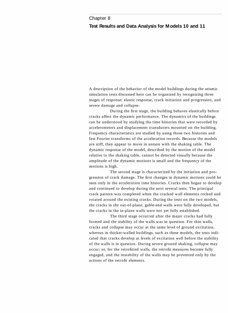
A description of the behavior of the model buildings during the seismicsimulation tests discussed here can be organized by recognizing threestages of response: elastic response, crack initiation and progression, andsevere damage and collapse.
During the first stage, the building behaves elastically beforecracks affect the dynamic performance. The dynamics of the buildingscan be understood by studying the time histories that were recorded byaccelerometers and displacement transducers mounted on the building.Frequency characteristics are studied by using those two histories andfast Fourier transforms of the acceleration records. Because the modelsare stiff, they appear to move in unison with the shaking table. Thedynamic response of the model, described by the motion of the modelrelative to the shaking table, cannot be detected visually because theamplitude of the dynamic motions is small and the frequency of themotions is high.
The second stage is characterized by the initiation and pro-gression of crack damage. The first changes in dynamic motions could beseen only in the acceleration time histories. Cracks then began to developand continued to develop during the next several tests. The principalcrack pattern was completed when the cracked wall elements rocked androtated around the existing cracks. During the tests on the two models,the cracks in the out-of-plane, gable-end walls were fully developed, butthe cracks in the in-plane walls were not yet fully established.
The third stage occurred after the major cracks had fullyformed and the stability of the walls was in question. For thin walls,cracks and collapse may occur at the same level of ground excitation,whereas in thicker-walled buildings, such as these models, the tests indi-cated that cracks develop at levels of excitation well before the stabilityof the walls is in question. During severe ground shaking, collapse mayoccur; or, for the retrofitted walls, the retrofit measures become fullyengaged, and the instability of the walls may be prevented only by theactions of the retrofit elements.
Chapter 8
Test Results and Data Analysis for Models 10 and 11

Model 10—Unretrofitted
Model 10 was an unretrofitted control model. The roof system had mini-mal, widely spaced roof sheathing. Nevertheless, during large displace-ments of the gable-end walls, the roof system still had enough stiffness toaffect the out-of-plane performance of those walls. The mode of failurewas a simple overturning of the wall and an out-of-plane collapse initi-ated near the mid-height of the wall.
Elastic responseThe dynamic response of the undamaged control building was largely asexpected. The time histories of the wall and table accelerometers areshown in figure 8.1. By comparing the peak values for each plot, it canbe seen that the peak acceleration at the top of the west wall (0.332 g)
104 Chapter 8
Time (sec.)Max. 5 20.332 at 8.26 sec.
Top of west wall
Max. 5 0.183 at 9.16 sec.
Middle west wall
Max. 5 20.207 at 9.30 sec.
Middle east wall
Max. 5 0.123 at 9.14 sec.
Top of north wall
Max. 5 0.105 at 3.78 sec.
Top of south wall
Shaking table
Max. 5 0.110 at 9.14 sec.
0.40
0.20
0.00
20.20
20.40
0.40
0.20
0.00
20.20
20.40
0.40
0.20
0.00
20.20
20.40
0.150.100.050.00
20.0520.1020.15
0.150.100.050.00
20.0520.1020.15
0.150.100.050.00
20.0520.1020.15
0.0 5.0 10.0 15.0 20.0
Acc
eler
atio
n (g
)
Figure 8.1
Acceleration measurements for model 10,
test II. The peak acceleration magnitude
and the time at which the peak occurred
are indicated by a circle around the maxi-
mum peak on the time-history plot. The
value on each plot is shown toward the
left side just above the top border of each
time history.

was approximately three times the peak acceleration of the shaking table,which was 0.110 g. Since the tops of the east and west gable-end wallswere coupled by the ridge beam, the acceleration at the top of the eastgable-end wall was not measured. At the mid-height of the west and eastwalls, the peak accelerations were 0.183 g and 0.207 g, respectively, indi-cating that the accelerations at this location were nearly twice the baseacceleration for the out-of-plane walls. Even though the anchorage atthis location was not strong, the tops of these walls probably moved inunison during low-level tests.
In contrast, the peak acceleration magnitudes of the in-plane(north and south) walls were only 0.123 g and 0.105 g, respectively.These values indicate that the motion of the in-plane walls was domi-nated by rigid-body motion; that is, the dynamic motion of these wallsclosely followed that of the base motion.
Transfer functions show the comparison of the frequencycharacteristics of one signal relative to a second signal. By examining atransfer function, one can determine the frequency ranges at which theamplification of motion occurs. The transfer functions for the top ofthe west gable-end wall, the middle of the west gable-end wall, and themiddle of the east gable-end wall were determined relative to the tableacceleration. The frequency plots indicate that the principal modewas between 8.0 and 8.5 hertz. This value is slightly lower than the9.8 hertz measured during the forced vibration tests (Gavrilovic et al.1996). The slightly lower frequency was probably due to the interactionbetween the shaking table and the heavy adobe structure when thetable was in the raised position during the dynamic tests. The forcedvibration frequencies were determined when the table was in the low-ered position, which resulted in a stiffer foundation system and lessstructure-foundation interaction.
Displacement time histories were not measured during thelow-level tests when the building was undamaged because the expecteddisplacements were too small; these data become important only duringhigh-level tests after cracks have developed.
Damage progressionCrack damage began during test III, when very small cracks occurred inboth east and west walls. In the west wall, the crack was horizontal atthe height of the north and south walls. In the east wall, the crack wasvertical and extended about halfway to the foundation. A small crackappeared in the upper left corner of the north wall caused by the out-of-plane motions of the east wall, which created tensile stresses in the northwall as it began to pull away. The dynamic motions of the upper sectionsof the walls were slightly discernible during test III and became much eas-ier to see during tests IV and V, when cracking became more significant.
The crack patterns after test V are illustrated in figure 8.2.The cracks in the gable-end walls show the variety and types of cracksthat can occur during out-of-plane motions of walls. In the east wall, thevertical crack below the window developed first, followed by the horizon-tal and diagonal cracks. In the west wall, the horizontal crack developed
Test Results and Data Analysis for Models 10 and 11 105

first and appeared to have relieved much of the higher tensile stresses inthe wall, since there were no diagonal cracks in the lower section andonly a very small vertical crack below the horizontal crack. Note that thehorizontal cracks in both the east and west walls were located at the topsof the north and south walls. The floor line was several courses lower.Cracks developed at the upper corners of both window openings, as typi-cally occurs at openings in walls. The dynamic motions were apparentduring both tests IV and V, with the roof system rocking back and forthsignificantly. During test V, spalling of adobe along the major linesbecame more apparent, particularly along the horizontal cracks. Thepeak displacements at the tops of the gable-end walls during tests IVand V were 7.6 and 9.9 cm (3.0 and 3.9 in.), respectively.
The north and south walls were in plane; that is, the direc-tion of the table motions was parallel to the plane of these walls. Theonly cracks that occurred during these moderate-level tests were at theends of the walls, where the tensile stresses were high as a result ofthe gable-end walls pulling away from the in-plane walls.
Performance and collapse during severe ground motionsDocumentation of the progression of damage to the walls of model 10during tests VI–VIII are shown in figures 8.3–8.7. The stability of themodel building was challenged during each of these tests. It is unclear
106 Chapter 8
(a) (b)
(c) (d)
Figure 8.2
Diagram of model 10, test V, crack pat-
terns on (a) east wall; (b) north wall;
(c) west wall; and (d) south wall.
Cracks during this test
Preexisting cracks

to what extent the roof system restrained motions of the out-of-plane,gable-end walls, but the system had a significant effect on the stability ofthe walls based on the failure mode of the east wall during test VIII. Thefirst failure mode of a wall with little or no restraint at the top is simpleoverturning. Rather than overturning, however, the east gable-end wallcollapsed due to outward motion of the wall sections starting at theupper horizontal crack at about two-thirds the height of the wall.
During test VI (figs. 8.3 and 8.4), the out-of-plane motions ofthe gable-end walls were significant, with peak displacements of nearly16.5 cm (6.5 in.). Cracks developed more fully during this test and com-pleted the principal crack patterns for the out-of-plane walls. The pat-terns that occurred in the east and west walls were different due to thevariability in the adobe masonry and the asymmetry of the groundmotions. Spalling continued along the major cracks. Without therestraint of the roof system, the gable-end walls would have had a ten-dency toward instability. Minimal restraint was required to significantlyaffect the out-of-plane dynamics of thick walls.
During test VII (figs. 8.5 and 8.6), the out-of-plane motionswere very great and caused cracking and popping noises in the woodframing of the roof. The out-of-plane walls would very likely have over-turned had it not been for the restraint provided by the roof framingsystem. Spalling continued along the major cracks. Diagonal cracks
Test Results and Data Analysis for Models 10 and 11 107
(a) (b)
(c) (d)
Figure 8.3
Diagram of model 10, test VI, crack pat-
terns on (a) east wall; (b) north wall;
(c) west wall; and (d) south wall.
Cracks during this test
Preexisting cracks

developed during test VII in the north wall (fig. 8.5b). This was the firsttest during which typical diagonal in-plane cracks developed; there wereno similar in-plane cracks in the south wall. The out-of-plane displace-ment of the west gable-end wall was 23.6 cm (9.3 in.) during test VII.
The in-plane displacements of the north and south walls werenot accurately measured during test VII. Vertical cracks opened near thewest end of both the north and south walls, allowing out-of-planemotion of the entire west wall. The opening of the vertical crack in thesouth wall was visually larger than the vertical crack in the north wall(fig. 8.6d). The peak displacement on the south end was 7.4 cm (2.9 in.),more than three times the peak displacement at the north end.
During test VIII (fig. 8.7), the east wall collapsed from thecenter of the wall rather than overturning due to restraint by the roofsystem. Test VIII lasted only about 3 seconds because the programmedtable accelerations exceeded the capacity of the earthquake simulator.Due to the short length of the test, little additional damage occurred inthe other walls of the building. The overturning failure mode occurs byrotation about the lowest horizontal crack, and the maximum displace-ment occurs at the top of the wall (fig. 8.8a). This type of collapse isreferred to as “mid-height, out-of-plane collapse” (fig. 8.8b).
108 Chapter 8
(a) (b)
(c) (d)
Figure 8.4
Photographs of model 10, test VI, crack
patterns on (a) east wall; (b) north wall;
(c) west wall; (d) south wall, west side;
and (e) south wall, east side.
(e)

Test Results and Data Analysis for Models 10 and 11 109
(a)
(b)
(c)
(d)
Figure 8.5
Diagram of model 10, test VII, crack
patterns on (a) east wall; (b) north wall;
(c) west wall; and (d) south wall.
Cracks during this test
Preexisting cracks
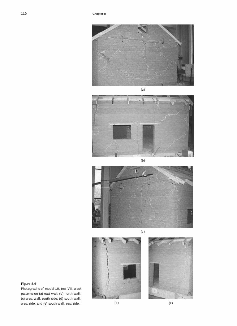
110 Chapter 8
(a)
(b)
(c)
(d) (e)
Figure 8.6
Photographs of model 10, test VII, crack
patterns on (a) east wall; (b) north wall;
(c) west wall, south side; (d) south wall,
west side; and (e) south wall, east side.

Test Results and Data Analysis for Models 10 and 11 111
(a) (b)
Figure 8.7
Model 10, test VIII, showing (a) east wall
collapse; and (b) crack patterns in north-
west corner.
(a) (b)
Figure 8.8
Drawings of out-of-plane modes of failure,
illustrating (a) typical overturning failure
as the wall rotates about its base; and
(b) mid-height, out-of-plane collapse
observed in the east wall of model 10.
The latter mode of collapse occurred due
to the restraint provided by the roof sys-
tem at the top of the wall.
Model 11—Retrofitted
The performance of the retrofitted model demonstrated the effectivenessof the installed retrofit system. Two different retrofit measures wereapplied to the two sets of in-plane and out-of-plane walls. The systemswere the same except for the difference in the vertical elements: thenorth and east walls were fitted with vertical straps on both sides of thewalls; the south and west walls were fitted with vertical center-core rods.
The elastic performance of the model may have been affectedby damage to the retrofitted model that occurred before testing began.The unretrofitted model 10 was constructed on a concrete slab that wasalready in place on the shaking table. Model 11, however, was con-structed on a concrete slab that was then moved to the shaking table.When this slab was bolted to the shaking table, it flexed and produced adeflection that resulted in minor crack damage to the building in thenortheast corner.
Restraint at top of wall

Elastic responseThe elastic response of the model may have been slightly affected byeither the preexisting cracks or the installation of the retrofit system.The modal frequencies in the east-west direction as determined from theambient vibration and forced vibration tests were 11.0 and 11.2 hertz,respectively (Gavrilovic et al. 1996). These values are slightly higher thanthose of model 10 and may be attributed to the stiffness of the roof andfloor diaphragms or to variation from one model to the other. The moreimportant observation is that the elastic behavior was not significantlyaffected by the preexisting cracks. Nevertheless, the locations of newcracks were clearly predetermined by the existing cracks.
Plots of the dynamic motions of the walls during test II areshown in figure 8.9. The peak acceleration of the top of the out-of-planewest wall was 0.359 g compared to the table acceleration maximum of0.111 g, an amplification factor of 3.25. The accelerations at the mid-
112 Chapter 8
TIME (seconds)Time (sec.)
Top of west wall
Middle west wall
Middle east wall
Top of north wall
Top of south wall
0.50
0.25
0.00
-0.25
-0.50
Max.= 0.359 at 9.900 sec.
0.50
0.25
0.00
-0.25
-0.50
Max.= 0.209 at 9.880 sec.
0.50
0.25
0.00
-0.25
-0.50
Max.= 0.227 at 13.860 sec.
0.150.100.050.00
-0.05-0.10-0.15
Max.= 0.124 at 9.16 sec.
0.150.100.050.00
-0.05-0.10-0.15
Max.= 0.127 at 9.16 sec.
0.150.100.050.00
-0.05-0.10-0.15
Max.= 0.111 at 9.14 sec.
0.0 5.0 10.0 15.0 20.0
Shaking table
Figure 8.9
Acceleration measurements for model 11,
test II. The peak acceleration magnitude
and the time at which the peak occurred
are indicated by a circle around the maxi-
mum peak on the time-history plot. The
value on each plot is shown toward the
left side just above the top border of each
time history.
Acc
eler
atio
n (g
)

height of the west and east walls were 0.209 g and 0.227 g, respectively.The accelerations of the north and south (in-plane) walls were 0.124 gand 0.127 g, respectively, only slightly greater than the table accelera-tion. It is also interesting to note that the peak acceleration of the dam-aged north wall was the same as that of the undamaged south wall.
The transfer functions for the wall accelerations of model 11were similar to those of model 10, except the amplification shown for theprincipal mode of vibration was about 8.5 or 9.0. This value is, again,slightly lower than that measured during the ambient and forced vibra-tion tests. All modal frequencies of model 11 were slightly higher thanthose of model 10.
Damage progressionNew crack damage did not develop until test IV or propagate until test V.The location of the crack damage after test V is shown in figure 8.10.Damage to the two out-of-plane walls was similar in some respects to thatin model 10 but different in others, indicating the influence of the retrofitstrategies. The vertical straps used on the west walls were not stiff enoughto prevent or change the development of crack damage in the wall. Thestrap system affected only the dynamic performance after cracks haddeveloped. As a result, the crack pattern in the east out-of-plane, gable-end wall consisted of both vertical and horizontal cracks similar to those
Test Results and Data Analysis for Models 10 and 11 113
(a) (b)
(c) (d)
Figure 8.10
Diagrams of model 11, test V, crack pat-
terns on (a) east wall; (b) north wall;
(c) west wall; and (d) south wall. Earlier
cracks are marked with zeros and dashed
lines.
Cracks during this test
Preexisting cracks
Straps
Center cores

that occurred in model 10. The horizontal crack at or near the tops of thein-plane walls was, again, similar to the damage in model 10.
Installation of center-core rods in the west wall of model 11had a clear effect on both the elastic and post-elastic behavior. Thecenter-core rods were anchored into the walls with epoxy grout, whichprovided sufficient strength and elasticity to allow shear transfer betweenthe adobe wall and the rods. As a result, the development of horizontalcracks was delayed until test VII. The vertical reinforcing rods strength-ened the adobe wall against flexure about the horizontal axis.
Since there were no horizontal rods, vertical cracks developedat roughly the same time as the cracks in the east wall. Restraint againstdeflection about the vertical axis was provided only by anchorage to theroof and floor diaphragms and the horizontal strap. These restraints werenot sufficient to prevent vertical cracks from occurring, however.
The in-plane north wall with vertical and horizontal strapsdeveloped additional cracks during both tests IV and V (fig. 8.10b).These cracks occurred earlier than in the in-plane walls of model 10 fortwo reasons: (1) some cracks existed before the testing began, and (2) theretrofit system resulted in higher forces being transferred to the in-planefrom the out-of-plane walls. More than likely, both factors contributedto greater cracking in the north wall of model 11 compared to the northwall of the unretrofitted model 10.
The south wall with vertical center-core rods suffered littledamage. A minor crack began at the upper right corner of the in-planesouth wall but appeared to stop when the crack reached the epoxy-anchored, center-core rods.
In viewing the dynamic tests, the cracks that developed dur-ing tests IV and V were relatively minor in terms of the amount of dis-placement that occurred in the out-of-plane walls. In the photographs offigure 8.11, it is difficult to discern the locations of the cracks becausethey were highlighted with chalk only, and no spalling had occurredaround the cracks. Not until test VI did larger displacements develop andspalling become significant.
Performance during severe ground motionsDuring the strong ground motions of tests VI–VIII, all of the retrofitmeasures on the building became significant with regard to the perfor-mance of model 11. The walls with vertical straps, both in-plane andout-of-plane, sustained much higher levels of damage than the walls withthe vertical center cores. The drawings and photographs of model 11after test VII are shown in figures 8.12 and 8.13.
During test VI, the east wall began to sustain significant dis-placements, and spalling occurred along crack lines, particularly alonghorizontal cracks. The most significant additional cracks were in the eastwall. Despite the spalling of material, the building did not suffer anymeasurable offsets at the cracks.
Test VII was informative because of the significant differencein the behavior of the two sets of walls. The north and east walls withvertical straps suffered large displacements, spalling, and significant off-
114 Chapter 8

sets, whereas the south and west walls with center-core rods sustainedrelatively minor damage. Cracks continued to develop in the south andwest walls, but these were relatively minor, and there were no offsets.
The extent of damage to the north and east walls contrastssharply with the low level of damage in the south and west walls.Spalling continued, with large cracks opening on the east and northwalls and permanent offsets at several cracks. The dynamic motions ofthe east gable-end wall were very great, causing relatively large loads todevelop in the vertical and horizontal straps.
Test Results and Data Analysis for Models 10 and 11 115
(a) (b)
(c) (d)
(e) (f)
Figure 8.11
Photographs of model 11, test V, crack
patterns on (a) east wall; (b) north wall;
(c) west wall; (d) west wall gable;
(e) south wall, west side; and (f) south
wall, east side.

116 Chapter 8
(a)
(b)
(c)
(d)
Figure 8.12
Diagram of model 11, test VII, crack pat-
terns on (a) east wall; (b) north wall;
(c) west wall; and (d) south wall.
Cracks during this test
Preexisting cracks
Straps
Center cores
The most significant damage may have been the displacementof the block at the east end of the north wall (fig. 8.13b). The sectionof the wall defined by the diagonal cracks at the upper and lower leftcorners of the window created a cracked wall section along which thepermanent displacements continued to grow as the tests proceeded,beginning with test VII. The crack at the top of this panel developed apermanent displacement of approximately 3.8 cm (1.5 in.) during thistest, and significant loads were applied to both the upper and lower hori-zontal straps. The load on the upper strap was great enough to result ina secondary horizontal crack that developed just below this strap. Thissection of wall was difficult to restrain because it continued to movedownward and out along the lower diagonal crack. Gravity and dynamicmotions continually moved this section outward. In this type of damage,a diagonal crack at the end of a wall section creates a condition in whichdamage progressively worsens during continued earthquake motions andmay eventually lead to catastrophic failure.
The shaking-table motions for test VIII* on model 11 wereslightly smaller than those for the same test on model 10. During the lat-ter test, the programmed table motions exceeded the acceleration capac-ity of the shaking table, and the system shut down after the first fewseconds of the test sequence. The acceleration for test VIII* on model 11was decreased to try to prevent overloading; this was not successful, andthe shaking table stopped after a few seconds into the test sequence.
Test Results and Data Analysis for Models 10 and 11 117
(a) (b)
(c) (d) (e) (f)
Figure 8.13
Photographs of model 11, test VII, crack
patterns on (a) east wall; (b) north wall;
(c) west wall gable; (d) west wall, south
side; (e) south wall, west side; and
(f) south wall, east side.

Several other attempts were made using a filtered displacement record,but since the table motions were dominated mostly by large accelera-tions, the table capacity (determined by the force capacity of the system)was exceeded and the system shut down each time.
Large displacements were obtained during test VIII* bydecreasing the time-scaling factor from 2 to 1.5. Because the model was1:2 scale and neglected gravity loads, the correct test acceleration wasobtained by multiplying the original accelerations by a factor of 2. Oncethe model was severely cracked, however, the development of large dis-placements was the most characteristic effect of the ground motions. TestVIII* had the same table displacements as the previous test VIII formodel 10, but the duration of the test was slightly longer. All accelera-tions were 50% greater, rather than 100% greater, than the originalrecord. Since the force on the drive system for the shaking table is afunction of peak acceleration times mass, this decrease was sufficient toprevent overloading of the shaking-table control system. Figure 8.14shows model 11 after test VIII*.
The east gable-end wall suffered significant additional dam-age during test VIII*. A small block just below the window was dis-lodged (see fig. 8.14a), and the offsets at the cracks in the center werenearly 7.6 cm (3 in.). Although large dynamic displacements occurredduring the test, the wall never appeared to have been close to collapse.
118 Chapter 8
Figure 8.14
Model 11, test VIII*, crack patterns on
(a) east wall; (b) north wall; (c) west wall,
south side; (d) west wall, north side;
(e) south wall, west side; and (f) south
wall, east side.
(a) (b)
(c) (d) (e) (f)

Damage to the north wall continued to worsen, with addi-tional cracks at the upper right corner of the door opening. The largeoffset at the cracked wall section on the left (east) end of the wallbecame slightly greater, but the tension in the upper and lower strapswas sufficient to prevent considerably larger displacements from occur-ring at this location.
The west and south walls continued to perform very well.The crack pattern generally remained stable, and no significant spallingoccurred. There were no offsets at any of the cracks in these walls, againdemonstrating the effectiveness of the center-core rods.
During test VII, the maximum displacements took place atthe top of the gable end of the structure and measured 7.9 cm (3.1 in.).The maximum displacement at the attic-floor level was 5.3 cm (2.1 in.).In-plane displacements were measured at the west end of the buildingwith linear potentiometers. As a result, the measurements were undoubt-edly affected by crack damage near the west wall. The north wall suf-fered more damage than the south wall and accordingly showed a largepeak displacement of 5.3 cm (2.1 in.), whereas the maximum displace-ment of the south wall was just less than 2.5 cm (1 in.). Neither of thein-plane walls, particularly the north wall, was displaced as much asthese measurements indicated, but the cracked section closest to the mea-suring device was displaced by this large amount.
Displacement of the top of the gable-end wall during test IVwas slightly less than 2.5 cm (1 in.) and increased to nearly 8.5 cm(3.4 in.) during test VIII*. These displacements were considerably smallerthan those of model 10.
Loads on Elements of the Retrofit System
Loads on the elements of the retrofit system of model 11 were measuredduring the test sequences. The elements measured were the horizontalstraps, the vertical straps on the east wall, and the ties to the floor fram-ing on both the east and west walls. Once again, all measurements wereconverted from the model to the prototype domain. To do so, the forcesmeasured in the model must be multiplied by a factor of 4 (the square ofthe inverse of the scaling factor).
Loading in the horizontal strap was highest on the east wall,where the vertical retrofit element consisted of exterior straps. The westwall was retrofitted with vertical center-core elements, which providedmore restraint to the out-of-plane movements of the gable-end wall thanthat provided by the vertical straps. The extent of damage during higher-level tests and the number of permanent cracks in the east and west wallsindicate the extent to which the horizontal straps were functioning. Theeast wall sustained many more cracks and permanent offsets than thewest wall. During the dynamic motion tests, the magnitude of out-of-plane motions was considerably greater in the east wall, resulting in highload levels in the east wall horizontal strap.
Test Results and Data Analysis for Models 10 and 11 119

The load levels in the horizontal straps on the east wall werehighest in tests VII and VIII*. Maximum load was 286 kg (631 lb.) inthe prototype domain. Because the upper horizontal strap was continu-ous around the building, the loads measured in the west wall may havebeen affected by those in the east wall. However, the strap could havelost some tension around each of two corners before reaching the westwall, and therefore it is not possible to know if the measured loading inthe east wall influenced the dynamic motions of the west wall. The eastwall loads were probably not affected by the motions of the west wall,given the low displacement levels and the minimal extent of crack dam-age. The loads in the west wall horizontal strap were less than 25% ofthose measured in the east wall horizontal strap.
Loads in the vertical straps on the east wall were less thanthose in the horizontal straps. The loads were highest in tests VII andVIII*, with a maximum value of nearly 55 kg (120 lbs.). The highestload in the vertical straps occurred during test VII, whereas the highestload in the horizontal strap occurred during test VIII*.
Measured loads in the crossties were much higher during testVIII* than in the previous tests for crossties in the east wall. Crosstiesconnected the horizontal strap to the floor diaphragm, and maximum loadvalues were about 172 kg (380 lbs.). The loads were considerably lowerin the west wall, only 33 kg (72 lbs.). The difference in values was a clearindication of the level of restraint provided by the straps. The crosstiesthrough the east wall were very highly loaded because high levels ofrestraint were required. Alternatively, the primary strengthening and stabi-lizing element in the west wall was provided by the center-core reinforcingelements, which resulted in lower loads in the crosstie elements.
The measured loads in the straps and crossties could be usedas a preliminary guide for designing the elements of a similar retrofitsystem. Rough calculations could be made using the geometry of theretrofitted model to determine the levels of loading that would occur.However, one difficulty is that the strap loading is determined by con-tributions from both the vertical and horizontal components. Furtherdetailed measurements of strap and crosstie loads would be required todevelop reliable engineering design data. Nevertheless, the magnitude ofthese loads was considerably less than would have been predicted by asimple static analysis.
The key to a structural retrofit system is its ductility; it isdifficult for any of these connections to fail. The connections are ductilebecause crossties can yield, bearing areas can dig into the adobe, andstraps (in both directions) can also stretch to redistribute the loading.
It would not be appropriate to use the loads developed in thistesting program for a retrofit system with nonductile connections. Brittleconnections must be designed for much higher load levels. In general,brittle connections are greatly discouraged in adobe retrofit systems.Shear anchors are ductile because the adobe around the anchors willmost likely fail. Tension anchors are brittle and cannot be recommendedfor the design of retrofit systems in adobe buildings.
120 Chapter 8
Analysis and discussion of resultsThe effectiveness of the retrofit system was evidenced by the
improved performance of the walls of the retrofitted model. Both theretrofit system with the vertical straps and the system with the center-corerods provided a great improvement in the ductility of the structural sys-tem compared to the unretrofitted model. The performance and collapseof the unretrofitted model demonstrated the fragility and danger of unre-inforced adobe construction. Both types of retrofit systems reduced theamount of severe damage and dramatically decreased the risk of collapse.The set of walls retrofitted with vertical center-core rods also delayed thedevelopment of cracks and reduced the extent of moderate damage.
Following is a brief comparison of the behavior of the modelsduring the three response stages. (A more detailed comparison is given inTolles and Ginell 2000.)
Comparison of elastic responseThe elastic response of the two model buildings was similar in manyrespects. The largest factor affecting the elastic response was probablythe additional stiffness added to the roof and floor systems of model 11.As a result, the frequency of the principal mode of vibration, as determinedby the ambient vibration tests, increased from 9.8 hertz in model 10 to11.2 hertz in model 11. The preexisting crack damage to model 11 appearsto have had no significant effect on the principal mode of vibration.
Amplification of peak acceleration at the top of the gable-endwalls (out of plane) was approximately the same for both models. Tableacceleration was nearly identical for both models during test II (PGA 5
0.11 g), and peak acceleration at the tops of the walls was 0.33 g inmodel 10 and 0.36 g in model 11. This slight difference (less than 10%)may have been the result of the change in first-mode frequency but, as ismore likely, may be simply the random variation between test results. Ineither case, the difference is not significant.
In general, there was little amplification at the top of the in-plane walls. The peak accelerations measured at the tops of the northand south walls of model 10 were 0.123 g and 0.105 g, respectively.In model 11, the peak accelerations were 0.124 g and 0.127 g for thenorth and south walls, respectively. The results may have been more con-sistent in the two in-plane walls due to the effect of the roof and floordiaphragms on tying the building together. An additional high-frequencycomponent shown in model 10 may have been a result of model behaviorbut more likely was a function of the instrumentation or of how theinstrument was mounted.
Comparison of damage progressionThe first evidence of damage can be seen by examining degradation inacceleration transfer functions. Figure 8.15 shows plots of the transferfunction for model 10 during tests I–IV. There was little change betweentests I and II, as indicated by the similar shapes of the transfer functions.Significant degradation began during test III with the loss of the defined
Test Results and Data Analysis for Models 10 and 11 121

peaks in the 8–9 second range, which represents the principal mode ofvibration, and with the shortening of the flat part of the spectrum start-ing at zero and extending to the right. The spectrum of test IV showscomplete degradation even in the lowest part of the spectrum.
Comparison of the damage to the out-of-plane and in-planewalls for the two models is shown in figures 8.16 and 8.17, respectively.Drawings of the crack damage that developed during tests V–VII areshown in figures 8.18–8.23.
Crack development of the out-of-plane walls during moderate-level tests was affected by the retrofit system. The stiffness of the roofdiaphragm was sufficient to prevent horizontal cracks from occurringin both the east and west gable-end walls of model 11 during test IV,whereas both walls of model 10 developed horizontal cracks during testIII (fig. 8.16). Vertical cracks developed during test IV in both retrofittedand unretrofitted models.
Damage to the in-plane walls was also affected by the stiffen-ing and strengthening effect of the roof diaphragm. The in-plane walls ofmodel 10 developed tension cracks at the ends of the walls due to the
122 Chapter 8
20
10
0
20
10
0
20
10
0 0 2 4 6 8 10 12 14 16 18 20
20
10
0 0 2 4 6 8 10 12 14 16 18 20
0 2 4 6 8 10 12 14 16 18 20
0 2 4 6 8 10 12 14 16 18 20
tw1 j
tw2 j
tw3 j
tw4 j
Tran
sfer
func
tion
Frequency (hz)Test I
Frequency (hz)Test II
Frequency (hz)Test III
Frequency (hz)Test IV
Figure 8.15
Degradation of the frequency response of
model 10 during tests I–IV. Plots are the
acceleration transfer functions for the top
of the west gable-end wall.

pull-out forces exerted on them by the gable-end walls. The gable-endwalls were beginning to pull away from the in-plane walls, which led tocrack damage in the upper corners of the in-plane walls (fig. 8.17a, b).The in-plane walls of model 11 did not develop these cracks because ofrestraint on the dynamic motions of the out-of-plane walls provided bythe diaphragms.
In the in-plane walls of the retrofitted model, the only crackthat developed during test IV was the diagonal crack that extended fromthe upper right corner of the doorway in the north wall of model 11(fig. 8.17c). This crack occurred because the wall already had sustainedcrack damage and was subjected to greater loads from the roof and floordiaphragms, which transferred loads from the out-of-plane walls to thein-plane walls. It is not possible to determine the extent to which eachof these factors contributed to the development of these cracks. Duringtest V, a small in-plane crack also developed at the upper right corner ofthe doorway in the south wall (fig. 8.19d). This crack turned upward andterminated when it intersected the vertical center-core bar. Nevertheless,the development of a shear crack in the south wall indicated that theloading in the in-plane walls of the retrofitted model was greater thanthe loading in the corresponding walls of the unretrofitted model.
Crack damage to the out-of-plane walls continued to worsenduring tests V and VI as shown in figures 8.18 and 8.20, respectively.During test V, a horizontal crack developed in the east wall of model 11
Test Results and Data Analysis for Models 10 and 11 123
(a) (b)
(c) (d)
Figure 8.16
Comparison of crack patterns after test IV
in out-of-plane walls for (a) model 10,
unretrofitted east wall; (b) model 10,
unretrofitted west wall; (c) model 11,
retrofitted east wall; and (d) model 11,
retrofitted west wall. Solid lines indicate
cracks that occurred during test IV; dashed
lines indicate cracks that typically occurred
during test III.
Cracks during this test
Preexisting cracks
Straps
Center cores

124 Chapter 8
(a)
(b)
(c)
(d)
Figure 8.17
Comparison of crack patterns after test IV
in the in-plane walls for (a) model 10,
unretrofitted north wall; (b) model 10,
unretrofitted south wall; (c) model 11,
retrofitted north wall; and (d) model 11,
retrofitted south wall. Solid lines indicate
cracks that occurred during test IV;
dashed lines indicate cracks that typically
occurred during test III; cracks labeled “0”
occurred before the start of the test series.
Cracks during this test
Preexisting cracks
Straps
Center cores

Test Results and Data Analysis for Models 10 and 11 125
Figure 8.18
Comparison of crack patterns after test V
in out-of-plane walls for (a) model 10,
unretrofitted east wall; (b) model 10,
unretrofitted west wall; (c) model 11,
retrofitted east wall; and (d) model 11,
retrofitted west wall.
Cracks during this test
Preexisting cracks
Straps
Center cores
(a)
(b)
(c)
(d)

(fig. 8.18c). The roof system restrained the top of the wall, but the ver-tical straps were not able to prevent this type of damage. The crackdamage to the east wall of models 10 and 11 was similar though notidentical (fig. 8.20a, c). The vertical and horizontal strap system had nosignificant effect on the elastic behavior and crack development; it hadan observable effect only after cracks had developed and displacementswere large. Nevertheless, the effect of the strapping system is verysignificant. Stiffness of the roof diaphragm affected all phases ofdynamic performance.
The crack damage to the west wall of model 11 shows thesignificant effect of the center-core rods. Through test VI (fig. 8.20), theonly long cracks in the west wall were the vertical crack at the center ofthe wall and the vertical crack on the right (south) side of the wall.Other cracks in the wall were small and not significant. The center-corerods prevented the development of any horizontal or diagonal cracksthrough test VI.
Crack damage to the in-plane walls continued to progress inboth walls of model 11 during tests V and VI (figs. 8.19 and 8.21). Inmodel 11, the damage to the north wall worsened considerably, whereasthe crack damage to the south wall propagated to the reinforcing bars,where the cracks terminated. In model 10, crack damage was limited tothe ends of the walls and was caused by tensile stresses, not in-planeshear stresses. The differences in behavior are due largely to the addi-tional loading that resulted from the anchorage to the roof and floordiaphragms.
126 Chapter 8
(a) (b)
(c) (d)
Figure 8.19
Comparison of crack patterns after test V
in the in-plane walls for (a) model 10,
unretrofitted north wall; (b) model 10,
unretrofitted south wall; (c) model 11,
retrofitted north wall; and (d) model 11,
retrofitted south wall.
Cracks during this test
Preexisting cracks
Straps
Center cores

Test Results and Data Analysis for Models 10 and 11 127
(a)
(b)
(c)
(d)
Figure 8.20
Comparison of crack patterns after test VI
in out-of-plane walls for (a) model 10,
unretrofitted east wall; (b) model 10,
unretrofitted west wall; (c) model 11,
retrofitted east wall; (d) model 11, retro-
fitted west wall.
Cracks during this test
Preexisting cracks
Straps
Center cores

128 Chapter 8
(a)
(b)
(c)
(d)
Figure 8.21
Comparison of crack patterns after test VI
in the in-plane walls for (a) model 10,
unretrofitted north wall; (b) model 10,
unretrofitted south wall; (c) model 11,
retrofitted north wall; and (d) model 11,
retrofitted south wall.
Cracks during this test
Preexisting cracks
Straps
Center cores

The effect of the retrofit system can be seen in the relativeout-of-plane displacements of the top of the west gable-end walls ofmodels 10 and 11 during tests V–VII (fig. 8.22). The displacements at themiddle of the west wall (fig. 8.23) were smaller than those in the eastwall because the strapping system allowed greater displacements thanthose in the wall retrofitted with center-core rods. The time historiesshow that the displacements in the retrofitted west gable-end wall wereapproximately one-third as large as those in the unretrofitted model asearly as test V, and the difference continued through test VII.
The opposite was true for the displacements of the in-planenorth and south walls (figs. 8.24 and 8.25, respectively), in which thedisplacements of model 11 were slightly larger than those of model 10.Displacements were measured at the west end of each wall and thereforeare not completely representative of the entire wall but may reflect thoseof cracked wall sections at the ends of the north and south walls. Thiscracking can be attributed largely to the additional loading transferred tothese walls through the diaphragm.
Comparison of performance during severe ground motionsThe out-of-plane walls of model 10 were potentially unstable during testVI and would most likely have collapsed during test VII if it were not
Test Results and Data Analysis for Models 10 and 11 129
Max. 5 3.105 at 7.160 sec.
Model 11—test VI
Max. 5 2.150 at 7.100 sec.
Model 11—test V
Max. 5 1.483 at 7.040 sec.
Model 10—test VII
Max. 5 29.359 at 4.120 sec.
Model 10—test VI
Max. 5 6.461 at 10.040 sec.
Max. 5 23.899 at 7.320 sec.
Model 10—test V
Model 11—test VII
Time (sec.)
5.000.00 10.00 15.00 20.00
10.005.00
25.00210.00
0.00
10.005.00
25.00210.00
0.00
10.005.00
25.00210.00
0.00
10.005.00
25.00210.00
0.00
10.005.00
25.00210.00
0.00
10.005.00
25.00210.00
0.00
Dis
pla
cem
ent (
in.)
Figure 8.22
Comparison of displacement measure-
ments at the top of the west gable-end
walls for models 10 and 11 during tests V,
VI, and VII.

for the restraint at the top of the wall provided by the roof system. Thedynamic motions led to large crack openings and rocking of the uppersection of the wall.
In contrast, the strengthened roof system of model 11 greatlylimited the displacements at the top of the wall. The maximum out-of-plane deflection at the top of the gable-end wall of model 11 was onlyone-third that observed in model 10 during test VII. The dynamicmotions of the east wall (with vertical straps) of model 11 were larger atthe center of the wall than at the top, based on visual observations of thevideotape recordings. The dynamic motions of the west wall were evenlydistributed over the height, with the largest displacements occurring atthe top of the gable-end wall due to the stiffening effects provided by thecenter-core rods. The displacements at the middle of the gable-end wall(at about two-thirds height location) were approximately two-thirds aslarge as the displacement at the top of the wall.
The out-of-plane displacements at the top of the gable-endwalls for model 11 were significantly smaller than those for model 10.The displacement of the west wall of model 10 during test VII was nearly23.9 cm (9.4 in.). Because the walls collapsed near the start of the fol-lowing test, a slightly larger displacement was required to cause instabil-ity. Therefore, the displacement for instability can be assumed to be
130 Chapter 8
Model 10—test V
Model 10—test VII
Model 10—test VI
Model 11—test V
Model 11—test VI
Model 11—test VII
Max.= 22.130 at 6.900 sec.
Max.= 21.556 at 9.800 sec.
Max.= 20.939 at 6.820 sec.
Max.= 26.486 at 4.160 sec.
Max.= 2.275 at 14.100 sec.
Max.= 1.390 at 9.840 sec.7.505.002.500.00
22.5025.0027.50
7.505.002.500.00
22.5025.0027.50
7.505.002.500.00
22.5025.0027.50
7.505.002.500.00
22.5025.0027.50
7.505.002.500.00
22.5025.0027.50
7.505.002.500.00
22.5025.0027.50
0.00 5.00 10.00 15.00 20.00
Time (sec.)
Figure 8.23
Comparison of displacement measure-
ments at the middle of the west gable-end
walls for models 10 and 11 during tests V,
VI, and VII.
Dis
pla
cem
ent (
in.)

approximately 25.4 cm (10 in.). For the retrofitted model, the largest dis-placement at the top of the gable-end wall during test VIII* was nearly8.9 cm (3.5 in.). This displacement value is only about one-third of thevalue required for instability to occur.
The response of these model buildings can be used to esti-mate the safety factor provided by the retrofit system with regard to therisk of overturning of the out-of-plane walls. Since the dynamic level ofdisplacement required to cause instability of the 40.6 cm (16 in.) thickwalls is at least 25.4 cm (10 in.), the safety factor for overturning wasabout a factor of 3.
Photographs of the damage to each wall after test VII appearin figures 8.26–8.29. Crack patterns are shown in figures 8.30 and 8.31.Damage to the out-of-plane walls was significant after test VII in bothwalls of model 10 and in the east wall of model 11 (fig. 8.30a–c). Althoughthe crack pattern was somewhat different, the extent of the cracks and theamount of spalling was similar in both models. The vertical straps had littleeffect on the extent of damage; their principal purpose was to reduce dam-age progression and prevent instability. The extent of damage to the westwall of model 11 was the least of all four walls because of the ductility andstrengthening provided by the center-core rods (fig. 8.27).
Test Results and Data Analysis for Models 10 and 11 131
Max. 5 0.686 at 9.800 sec.
Max. 5 0.910 at 6.880 sec.
Model 10—test V
Max. 5 0.887 at 9.020 sec.
Model 10—test VI
Max. 5 20.542 at 7.340 sec.
Model 10—test VII
Max. 5 20.882 at 9.840 sec.
Model 11—test V
Max. 5 2.158 at 13.520 sec.
Model 11—test VI
Model 11—test VII
5.000.00 10.00 15.00 20.00
5.002.50
22.5025.00
0.00
5.002.50
22.5025.00
0.00
5.002.50
22.5025.00
0.00
5.002.50
22.5025.00
0.00
5.002.50
22.5025.00
0.00
5.002.50
22.5025.00
0.00
Time (sec.)
Figure 8.24
Comparison of displacement measure-
ments of the north walls for models 10
and 11 during tests V, VI, and VII.
Dis
pla
cem
ent (
in.)
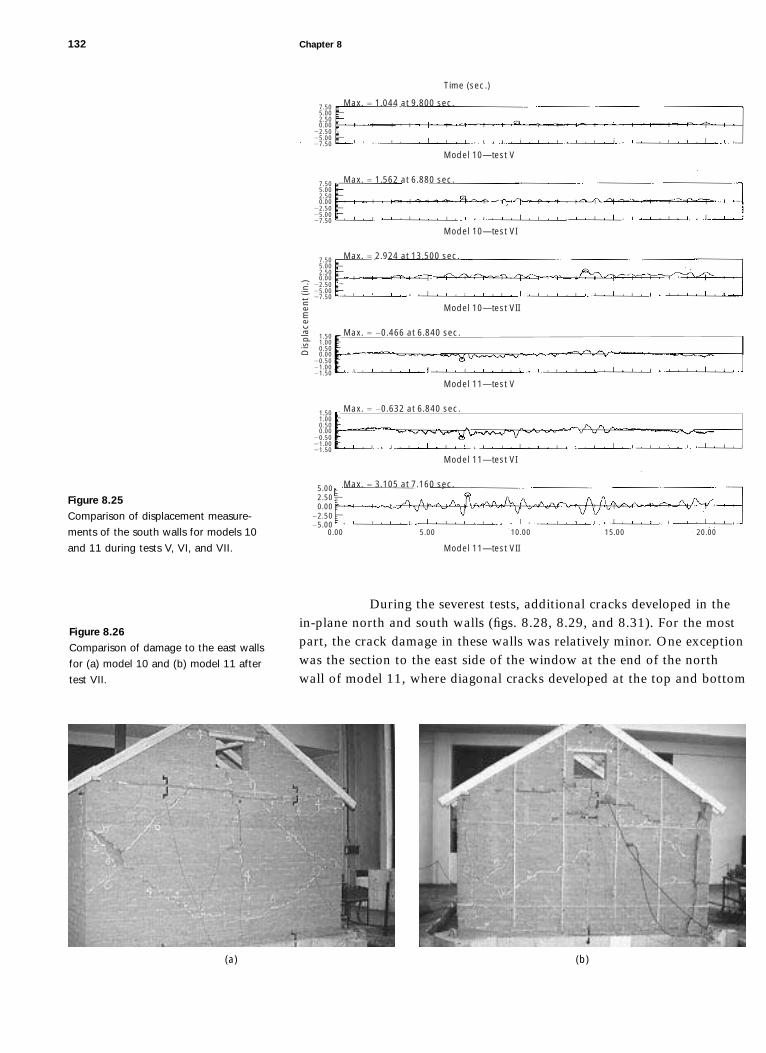
During the severest tests, additional cracks developed in thein-plane north and south walls (figs. 8.28, 8.29, and 8.31). For the mostpart, the crack damage in these walls was relatively minor. One exceptionwas the section to the east side of the window at the end of the northwall of model 11, where diagonal cracks developed at the top and bottom
132 Chapter 8
Max. 5 1.044 at 9.800 sec.
Max. 5 1.562 at 6.880 sec.
Model 10—test V
Max. 5 2.924 at 13.500 sec.
Model 10—test VI
Max. 5 20.466 at 6.840 sec.
Model 10—test VII
Max. 5 20.632 at 6.840 sec.
Model 11—test V
Max. 5 3.105 at 7.160 sec.
Model 11—test VI
Model 11—test VII
5.000.00 10.00 15.00 20.00
5.002.50
22.5025.00
0.00
0.501.001.50
0.0020.5021.0021.50
0.501.001.50
0.0020.5021.0021.50
2.505.007.50
0.0022.5025.0027.50
2.505.007.50
0.0022.5025.0027.50
2.505.007.50
0.0022.5025.0027.50
Time (sec.)
Dis
pla
cem
ent (
in.)
Figure 8.25
Comparison of displacement measure-
ments of the south walls for models 10
and 11 during tests V, VI, and VII.
(a) (b)
Figure 8.26
Comparison of damage to the east walls
for (a) model 10 and (b) model 11 after
test VII.
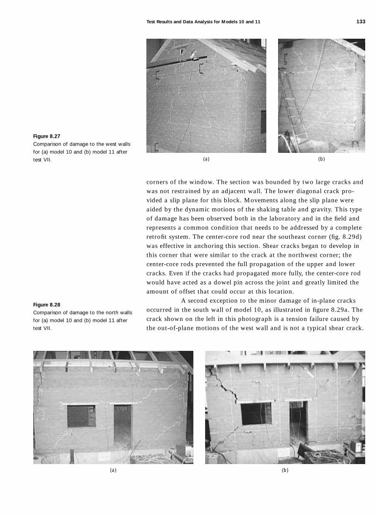
corners of the window. The section was bounded by two large cracks andwas not restrained by an adjacent wall. The lower diagonal crack pro-vided a slip plane for this block. Movements along the slip plane wereaided by the dynamic motions of the shaking table and gravity. This typeof damage has been observed both in the laboratory and in the field andrepresents a common condition that needs to be addressed by a completeretrofit system. The center-core rod near the southeast corner (fig. 8.29d)was effective in anchoring this section. Shear cracks began to develop inthis corner that were similar to the crack at the northwest corner; thecenter-core rods prevented the full propagation of the upper and lowercracks. Even if the cracks had propagated more fully, the center-core rodwould have acted as a dowel pin across the joint and greatly limited theamount of offset that could occur at this location.
A second exception to the minor damage of in-plane cracksoccurred in the south wall of model 10, as illustrated in figure 8.29a. Thecrack shown on the left in this photograph is a tension failure caused bythe out-of-plane motions of the west wall and is not a typical shear crack.
Test Results and Data Analysis for Models 10 and 11 133
(a) (b)
Figure 8.27
Comparison of damage to the west walls
for (a) model 10 and (b) model 11 after
test VII.
(a) (b)
Figure 8.28
Comparison of damage to the north walls
for (a) model 10 and (b) model 11 after
test VII.

Performance Observations and Summaries
Crack initiation in the out-of-plane walls of both model buildings beganduring tests III and IV, when peak table accelerations were 0.11 g and0.17 g, respectively. The only cracks in the in-plane walls, besides tensioncracks at the ends of the walls, did not occur until test VII in model 10,when the peak table acceleration was 0.47 g. Given the flexible roof sys-tem and the absence of interconnections between the walls, the loadingon the in-plane walls was due primarily to the dynamic forces caused bythe acceleration of the mass of the walls themselves. Based on simpleforce-resistance calculations, the in-plane shear walls failed when theshear stresses were at least 3 psi (2.06 N cm22). Additional loads may
134 Chapter 8
(a) (b)
Figure 8.29
Comparison of damage to the south walls
for models 10 and 11 after test VII, show-
ing (a) model 10, south wall, west side;
(b) model 10, south wall, east side;
(c) model 11, south wall, west side; and
(d) model 11, south wall, east side. (c) (d)

Test Results and Data Analysis for Models 10 and 11 135
(a) (b)
(c) (d)
Figure 8.30
Comparison of crack patterns after test VII
in the out-of-plane walls for (a) model 10,
unretrofitted east wall; (b) model 10,
unretrofitted west wall; (c) model 11,
retrofitted east wall; and (d) model 11,
retrofitted west wall.
Cracks during this test
Preexisting cracks
Straps
Center cores
have been transferred from the out-of-plane walls, and therefore thisstress level is a minimum value. This analysis is based on the observationthat the in-plane shear cracks in model 10 did not occur until test VII,when the PGA was 0.47 g. The calculation of mass is minimized by con-sidering only the mass of the walls above the door openings; the areaused is the gross minimum area at the window opening. No compensa-tion is made for the relative stiffness of the wall panels, and the self-weight of the shear walls is the only mass used in this analysis.
In the out-of-plane walls, full crack development occurredduring tests V (PGA 5 0.23 g) and VI (PGA 5 0.27 g). (Fig. 8.30 showscrack patterns in these walls after test VII.) Full crack development didnot occur in the in-plane walls, except perhaps in the north wall ofmodel 11 after test VIII*. (Fig. 8.31 shows crack patterns in these wallsafter test VII.) Full crack development is the point at which all the edgesof the major sections of a wall are defined by cracks. A drawing of thecrack pattern in the out-of-plane east wall of model 11 after test VI isshown in figure 8.32a. The major cracked sections or “blocks” of thiswall are labeled B1 through B5. Each section is bounded by a free sur-face or by a crack on all four sides. Despite the increased intensity of thetable motion in test VII, the only major crack that developed was theone that split B4 into two sections (fig. 8.32b). Once cracks developed,

136 Chapter 8
(a)
(b)
(c)
(d)
Figure 8.31
Comparison of crack patterns after test VII
in the in-plane walls for (a) model 10,
unretrofitted north wall; (b) model 10,
unretrofitted south wall; (c) model 11,
retrofitted north wall; and (d) model 11,
retrofitted south wall.
Cracks during this test
Preexisting cracks
Straps
Center cores

the primary dynamic behavior of the building was determined by thedynamic motions of the cracked wall sections. In this case, it is difficultto apply enough force to a block to cause it to crack further. Additionaldamage was largely caused by gradual degradation of the contact areasbetween each of the major cracked wall sections.
The strapping system used on the east wall of model 11 waseffective in providing wall stability. A drawing of the crack pattern aftertest VII and photographs showing the condition of the walls are pre-sented in figure 8.33. Cracks and spalling were significant, and an offsetof almost 5.1 cm (2 in.) occurred at the northeast corner (fig. 8.33c).
Test Results and Data Analysis for Models 10 and 11 137
(a) (b)
Figure 8.32
Crack pattern development in east wall of
model 11 (a) after test VI and (b) after
test VII. During test VI, the wall cracked
into five major sections, or blocks, labeled
B1 through B5. During test VII, three of
the major blocks remained intact, but B2
and B4 each cracked into two sections.
Cracks during this test
Preexisting cracks
Straps
Center cores
(a) (b)
(c)
Figure 8.33
Damage to model 11, east wall (retrofitted
with vertical straps) after test VII, shown
in (a) diagram of crack pattern, with ver-
tical lines indicating position of straps;
(b) photograph of strapped wall; and
(c) detail of north side of wall.
Cracks during this test
Preexisting cracks
Straps
Center cores

Although the east wall of model 10 collapsed, with failure occurring atabout the two-thirds height level, the east wall of model 11 was stableeven after the large displacement during test VIII*.
The center-core system used on the west wall of model 11performed extremely well. The condition of the wall after test VII isshown in figure 8.34. Although the full crack patterns developed duringtests VI, VII, and VIII*, the wall was stabilized by the center-core rods.There were no large cracks, offsets, or spalling on this wall; despite thecracks, the wall remained in very good condition.
The strapping system of model 11 was not effective in con-trolling the in-plane diagonal cracking at the east end of the north wall(fig. 8.35). The upper and lower straps were highly stressed, whichresulted in some damage to the adjacent adobe. Nevertheless, the strapscontinued to perform well throughout the testing program. Some addi-tional retrofit measures need to be installed to minimize this type of dam-age, which could lead to the collapse of the corner section of the wall.
The center-core elements in the south wall of model 11 wereextremely effective in controlling the initiation and progression of crackdamage (fig. 8.36). Three of the cracks that started at the corners of theopenings in the wall were arrested when they reached the center-corerods. In the later tests, the cracks continued to progress but neverbecame very large.
The roof system installed on the models had adequate stiff-ness to prevent large top-of-the-wall displacements, and the anchorage atthe tops of the walls minimized damage in these areas. The ties from thefloor diaphragm to the horizontal strap at the floor level performed well.No failures of any of these connections were observed. The through-tiesthat connected the straps on either side of the walls also performed wellthroughout.
Summary of Comparison of Performance of Small- and Large-Scale Models
Because the small-scale (1:5) models were not instrumented to recorddisplacements and accelerations, direct quantitative comparison with
138 Chapter 8
(a) (b) (c)
Figure 8.34
Damage to model 11, west wall (retro-
fitted with center-core rods) after test VII,
shown in (a) diagram of crack pattern;
(b) photograph of north side of wall; and
(c) photograph of south side of wall.
Cracks during this test
Preexisting cracks
Straps
Center cores
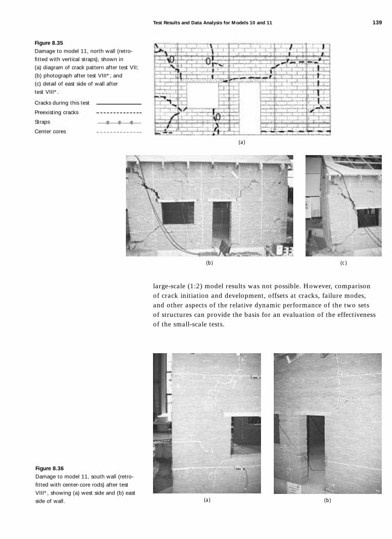
large-scale (1:2) model results was not possible. However, comparisonof crack initiation and development, offsets at cracks, failure modes,and other aspects of the relative dynamic performance of the two setsof structures can provide the basis for an evaluation of the effectivenessof the small-scale tests.
Test Results and Data Analysis for Models 10 and 11 139
(c)
(a)
(b)
Figure 8.35
Damage to model 11, north wall (retro-
fitted with vertical straps), shown in
(a) diagram of crack pattern after test VII;
(b) photograph after test VIII*; and
(c) detail of east side of wall after
test VIII*.
Cracks during this test
Preexisting cracks
Straps
Center cores
(a) (b)
Figure 8.36
Damage to model 11, south wall (retro-
fitted with center-core rods) after test
VIII*, showing (a) west side and (b) east
side of wall.

The elastic performance and early crack development modesof the small- and large-scale models were similar. The random develop-ment of cracks, the minor differences in shaking-table motions, and thevariation in adobe materials properties could have accounted for theminor behavioral differences among the tapanco-style models.
The types of behavior most affected by the scale of the mod-els became apparent at the higher displacement and acceleration levels.The most significant of these were out-of-plane overturning in the small-scale models and offsets resulting from in-plane diagonal cracks in thelarge-scale models. The risk of overturning failure may have been over-stated by the performance of the small-scale models, however. Becausethe mass of the wall is underrepresented at the 1:5 scale, and becausegreater masses resist overturning, this effect may have occurred at alower ground motion level than was found to occur in the 1:2 scale mod-els. In full-scale buildings, the high vertical gravity loads would tend toinhibit overturning.
Problems associated with damage to in-plane walls alongdiagonal cracks become more severe as the scale increases. Because of thegreater mass of the wall and the fact that the displacements along diago-nal cracks are cumulative, the effects produced may be more significantthan those resulting from restrictions to movement caused by increasedfriction between the moving blocks. Therefore, larger-scale models willtend to exhibit greater offset damage than smaller-scale models, and thisfailure mode is expected to be serious in unretrofitted, full-scale build-ings. Despite these differences, the overall performances of the small- andlarge-scale models were very similar, and the retrofit measures shown tobe effective on the small-scale models were also effective on their large-scale counterparts.
140 Chapter 8
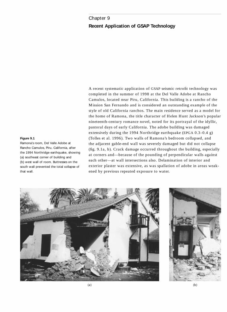
A recent systematic application of GSAP seismic retrofit technology wascompleted in the summer of 1998 at the Del Valle Adobe at RanchoCamulos, located near Piru, California. This building is a rancho of theMission San Fernando and is considered an outstanding example of thestyle of old California ranchos. The main residence served as a model forthe home of Ramona, the title character of Helen Hunt Jackson’s popularnineteenth-century romance novel, noted for its portrayal of the idyllic,pastoral days of early California. The adobe building was damagedextensively during the 1994 Northridge earthquake (EPGA 0.3–0.4 g)(Tolles et al. 1996). Two walls of Ramona’s bedroom collapsed, andthe adjacent gable-end wall was severely damaged but did not collapse(fig. 9.1a, b). Crack damage occurred throughout the building, especiallyat corners and—because of the pounding of perpendicular walls againsteach other—at wall intersections also. Delamination of interior andexterior plaster was extensive, as was spallation of adobe in areas weak-ened by previous repeated exposure to water.
Chapter 9
Recent Application of GSAP Technology
(a) (b)
Figure 9.1
Ramona’s room, Del Valle Adobe at
Rancho Camulos, Piru, California, after
the 1994 Northridge earthquake, showing
(a) southeast corner of building and
(b) west wall of room. Buttresses on the
south wall prevented the total collapse of
that wall.

In many locations, the walls had pulled away from the ceilingjoists, and damage to the walls further reduced their ability to supportthe joists. Three major physical conditions—water damage, preexistingcracks, and material weakness—influenced the performance of the DelValle Adobe during the Northridge earthquake. The most significant wasmoisture damage. There had been water damage to the lower adobewalls and foundation in several locations. Repeated wet/dry cycling hasresulted in deteriorated and weakened adobe at the base of many walls.To hide the moisture damage, the lower section of the adobe walls hadbeen covered in many areas with large concrete patches, which forced thewater to rise even higher in the walls.
The adobe material used at Rancho Camulos is a silty, sandysoil with a relatively small amount of clay. As a result, the walls crackedat relatively low levels of earthquake excitation. The building also hadmany cracks throughout the structure that occurred prior to the earth-quake. Judging from the nature of these cracks, it is likely that manyoccurred during previous earthquakes. The larger cracks had been filledwith concrete and covered with plaster. No seismic retrofitting had beendone prior to the earthquake. Although there are three stone buttressesoutside the corner bedroom (Ramona’s room) and one on the other westelevation of the west wing, it is likely that these were constructed to sta-bilize the walls for other reasons, such as moisture damage to the lowerwall. There is also a pair of wooden pilasters anchoring a tie rod thatwas probably installed in response to wall leaning. For the most part,there were no structural elements that could tie the walls together or tiethe roof-ceiling system to the walls.
At the request of rancho owners, a damage assessment wasmade and a retrofit and repair strategy was proposed by a private designteam headed by one of the authors (Tolles). The team worked with theCalifornia State Office of Historic Preservation and the Ventura CountyDepartment of Buildings and Safety to ensure that the retrofit design con-formed to the U.S. Secretary of the Interior’s Standards for Rehabilitationof Historic Buildings and requirements of existing local building codes.
The design of the retrofits for Rancho Camulos was basedlargely on the results of GSAP research.1 A careful review of the proposedretrofit measures was carried out by the designers and state and countyofficials. The measures that have been approved and installed includedplacing horizontal stainless-steel cables or nylon straps around perimeterwalls, which in some cases were anchored to ceiling joists (fig. 9.2a);installing vertical pre-tensioned steel cables on both sides of thin walls(SL . 8), or on walls that were particularly vulnerable because of previousearthquake damage (fig. 9.2b, c); inserting epoxy-grouted vertical center-core rods in newly constructed adobe walls; and installing appropriateanchorage between the walls and roof at the floor and ceiling levels.
142 Chapter 9
1Other California adobes whose retrofits were influenced in the past by some of theGSAP concepts were Courthouse Adobe, Shafter; O’Hara Adobe, Toluca Lake;Lydecker Adobe, Aptos; Jameson Adobe, Corona; and the Mission San Gabrielconvento, San Gabriel.

Recent Application of GSAP Technology 143
(a) (b)
(c)
Figure 9.2
Installation of steel cables at the Del Valle
Adobe, showing (a) horizontal cable
anchored to ceiling joists; (b) vertical cable
installed in previously damaged walls; and
(c) enlarged detail of cable anchor (area of
enlargement shown in b).

This first implementation of all the principal retrofit tech-niques studied in GSAP required some redesign of laboratory-testeddetails for application to real-world conditions, as well as review andacceptance by architectural and engineering building officials andofficials of the California State Office of Historic Preservation. The pro-ject also required input and review by the buildings’ owners, who wereparticularly concerned with preserving the historic features and maintain-ing safety in and around the buildings.
144 Chapter 9

The goal of the Getty Seismic Adobe Project, as stated in the project’sfirst annual report (Thiel et al. 1991), was “to develop technical proce-dures for improving the seismic performance of existing monumentaladobe structures consistent with maintaining architectural, historic, andcultural conservation values.”
Although the application to monumental adobe structures hasonly begun, the tests performed and the results obtained demonstratethat retrofit measures can be used effectively to provide life safety byminimizing the likelihood of catastrophic collapse while having only aminimal impact on the historic fabric of the retrofitted building. In theyears prior to the initiation of GSAP, some gains had been made by theengineering community in developing retrofit measures that were sensi-tive to the issue of preservation of historic building fabric. Nevertheless,there was very little information about how these less intrusive retrofitsystems would, in fact, behave.
The results of the GSAP research effort, involving small- andlarge-scale seismic simulation tests on adobe buildings, has providedthe necessary technical information to justify the use of less intrusiveretrofit measures.
The principal technical accomplishments of GSAP were
• Development of the basic theoretical framework for under-standing seismic retrofit systems for adobe buildings.
• Development of retrofit systems that are likely to be veryeffective in providing life safety and in minimizing theextent of damage.
• Testing of a set of retrofit tools that can be used on historicadobe buildings.
• Presentation of reports on the project and publication oftechnical papers on the studies.
• Development of planning and engineering guides to assistowners, building department officials, engineers, architects,and conservators in defining the requirements and indesigning retrofit systems for historic adobe buildings(Tolles, Kimbro, and Ginell n.d.).
Chapter 10
Summary and Conclusions

146 Chapter 10
• Documentation of the study of the relative seismic per-formance of historic adobe buildings affected by theNorthridge earthquake on January 17, 1994 (Tolles et al.1996). The results of this survey are significant in that theyrepresent the behavior of real buildings during a large-scaleearthquake and provide important information that can beuseful in understanding the performance of historic adobebuildings and in developing retrofit techniques.
Protection of historic fabric has been a serious considerationthroughout the GSAP research program. A variety of techniques weresuggested and tested that might apply to the various building conditionsencountered in the field. This multidisciplinary approach, coupled withthe counsel provided by the GSAP Advisory Committee, makes thisresearch program unique in its application to historic buildings.
Assessment of Retrofit Measures
The retrofit systems tested in GSAP involved horizontal and verticalstraps, ties, vertical center-core rods, and improvements in the anchoringof the roof to the walls. Each method proved to be successful in reducingthe tendency of the model buildings to collapse.
The retrofit method using vertical straps was most effectivefor reducing the risk of out-of-plane wall collapse. Vertical straps hadlittle or no effect on the initiation and early development of crack dam-age. When displacements or offsets became significant, however, thestrapping system controlled the relative displacement of cracked sectionsof walls, which, if left uncontrolled, led to instability. When coupledwith tied anchorage to the roof and/or floor system, the out-of-planeoverturning or mid-height collapse of walls can be prevented.
In-plane damage was much less affected by vertical straps.This is largely because in-plane offsets are smaller in magnitude andmore likely to persist after the dynamic motions are completed. Strapscan prevent large displacements but not small crack offsets. Straps arealso useful in preventing piers from becoming unstable.
Vertical center-core rods installed in the adobe walls werefound to be particularly effective in delaying and limiting the damageto both in-plane and out-of-plane walls. The initiation of cracks wasdelayed because of the center-core rods. Some cracks in the in-planewalls that started at the corners of the door and window openings propa-gated to a center-core rod and then were arrested for one or two moretests. The cracks never became severe.
In the out-of-plane walls, the center-core rods acted as rein-forcing elements. Epoxy grout surrounding the rods provided effectiveshear transfer between the adobe and the steel rods. The epoxy soakedinto the adobe unevenly because of the variation in the walls, especiallyat the mortar joints, and therefore provided a positive attachmentbetween the steel rods and the adobe walls. The walls with center-

core rods were then able to act as structural reinforcing elements in thevertical direction. In addition, the rods acted as dowel pins that mini-mized the relative motion of adobe blocks. Removal of such rodswould be difficult.
One advantage of the strapping system is that the installa-tion has minimal impact on the historic fabric of the wall and is alsoreversible. If surface renderings such as murals are important, then theinterventions required for installation of a strapping system would not beappropriate. For most historic buildings, however, surface renderings ofthe walls are not particularly significant, especially in cases where thereis deterioration of the plaster/stucco or damage has occurred from anearthquake. When disturbance of the wall surface is unacceptable, theuse of center cores will avoid damage to wall surfaces.
Relative Model Performance
The performance of small- and large-scale model buildings was verysimilar in many ways. The general development of cracks, the types ofcracks, and the failure modes were similar. The effects of the retrofitmeasures on building behavior were also similar. For the most part, thebehavior of the small-scale models was an acceptable predictor of large-scale model performance.
The principal physical difference between the small- andlarge-scale models was in gravity loads. As a result, specific differenceswere seen in both the out-of-plane and in-plane wall performances.Global performances were very similar. The most outstanding differencewas the occurrence of diagonal cracks in the in-plane walls. Diagonalcracks allow displacements that are cumulative and slippage that is exac-erbated by vertical loads. As a result, diagonal cracks were more of aproblem in the larger-scale model and would be expected to be at least asserious a problem in full-scale buildings, in which diagonal cracks nearthe ends of piers and walls are of particular concern.
On the one hand, overturning of walls is less of a problem infull-scale buildings because the vertical loads resist overturning. On theother hand, the condition of the base of the walls in the model buildingswas very good. In many actual adobe buildings, the adobe at the base ofthe walls has often been weakened by exposure to moisture, and wallsthat are weakened at the base are highly vulnerable to overturning.
The performance of adobe buildings was demonstrated inreal-world terms by the 1994 Northridge earthquake, in which many his-toric adobe buildings were seriously damaged. Given that this researchprogram was under way and that there was a dearth of informationregarding the past performance of earthquake-damaged adobe buildings,this destructive event did, however, provide a fortuitous opportunity forcomparison of field observations, scientific analysis of actual buildings,and the results of laboratory testing.
Despite the information gained from the Northridge earth-quake, there is still much that may be derived from a study of the
Summary and Conclusions 147

performance of well-retrofitted adobe buildings during a major earth-quake. Some of the buildings damaged during the Northridge earthquakehad been partially retrofitted, but these measures were implemented in apiecemeal manner, and none provided an integrated retrofit system. Morecomplete information on the performance of systematically retrofittedadobe buildings will be obtained after major earthquakes in the future.The development of engineering standards is based on engineering analy-sis, research, and field observations. Information presently available onthe basic performance of adobe buildings is significant and can be usedas the basis for developing standards for the performance and seismicretrofit of these important historic structures.
148 Chapter 10
The Getty Seismic Adobe Project has not answered all of the relevantquestions regarding the design of seismic retrofit systems for historicadobe buildings. Other areas for future research are
• Connections. This area has not been addressed in detail inthe GSAP research effort, particularly for the tops of walls,where durable connections are difficult to make. Largeloads at connections into adobe walls can result in addi-tional damage. Planning and Engineering Guidelines forthe Seismic Stabilization of Historic Adobe Structures(Tolles, Kimbro, and Ginell n.d.) will discuss methods forpredicting and planning for this damage. Nevertheless, therequired strength of these connections has not been directlyaddressed.
• Strong-motion instrumentation. Data collected on thebehavior of historic adobe buildings during an actualearthquake event should be useful in analyzing the perfor-mance of these structures. The interaction between existingroof systems and the adobe walls is one area where addi-tional data are needed. Relatively few historic adobe build-ings remain, and the chances of getting information anytime in the near future may be low. Nevertheless, the dataobtained from such an investigation may be extremelyvaluable and, perhaps more important, may be reassuringto those who have questions about other conclusionsdrawn from past research.
• Analytical methodologies. The work conducted throughGSAP concerns the development of basic strategies fordesigning seismic retrofits of historic adobe buildings.More extensive work is necessary to turn these methodsinto analytical procedures. The analysis should include thecomplex interaction between a thick adobe wall rockingout of plane and supported by a flexible diaphragm (eitherplywood, straight sheathing, or a partial diaphragm) and
Chapter 11
Suggestions for Future Research

in-plane walls that have suffered crack damage. This com-plex system could be addressed either analytically or byusing information based on actual test results.
The GSAP research effort has provided significant additions tothe body of knowledge on the behavior of adobe structures retrofittedaccording to stability-based design principles. Much work remains to bedone in the future; for now, at least, a foundation exists for the design ofseismic retrofits for both historic and nonhistoric adobe buildings.
150 Chapter 11

Bariola Bernales, Juan J.1986 Dynamic stability of adobe walls. Ph.D. diss., University of Illinois at Urbana-
Champaign.
Gavrilovic, P., V. Sendova, L. Taskov, L. Krstevska, E. Leroy Tolles, and W. S. Ginell1996 Shaking table tests of adobe structures. Report, IZIIS 96-36, Institute of
Earthquake Engineering and Engineering Seismology, Skopje, Republic ofMacedonia, and Getty Conservation Institute, Los Angeles, June.
Meli, Roberto, Oscar Hernandez, and M. Padilla1980 Strengthening of adobe houses for seismic actions. In Proceedings of the Seventh
World Conference on Earthquake Engineering. Istanbul: Turkish NationalCommittee on Earthquake Engineering.
Molino de Garcia, Maria Elena1990 Prevención sísmica en las construcciones de adobe, en la cuidad de Guatemala
después de los terremotos de 1917–1918. Paper presented at the SixthInternational Conference on the Conservation of Earthen Architecture, LasCruces, N.Mex., October 14–19.
Moncarz, Piotr D., and Helmut Krawinkler1981 Theory and application of experimental model analysis in earthquake engineer-
ing. Report no. 50, John A. Blume Earthquake Engineering Center, Departmentof Civil Engineering, Stanford University, Palo Alto, Calif., June.
Scawthorn, Charles, and Ann M. Becker1986 Relative benefits of alternative strengthening methods for low strength masonry
buildings. In Proceedings of the Third National Conference on EarthquakeEngineering, Charleston, South Carolina. Oakland, Calif.: EarthquakeEngineering Institute.
State Historic Building Code1990 State of California, Title 24, Building Standards, part 8, June.
Thiel, Charles C., Jr., E. Leroy Tolles, Edna E. Kimbro, Frederick A. Webster, andWilliam S. Ginell1991 GSAP—Getty Conservation Institute guidelines for seismic strengthening of
adobe project: Report of first year activities. Report, Getty ConservationInstitute, Marina del Rey, Calif., October 1.
Tolles, E. Leroy, and William S. Ginell2000 Getty seismic adobe project (GSAP): Analysis of the results of shaking table
tests on large scale model adobe structures. Report, Getty ConservationInstitute, Los Angeles.
Tolles, E. Leroy, Edna E. Kimbro, and William S. Ginell n.d. Planning and Engineering Guidelines for the Seismic Stabilization of Historic
Adobe Structures. GCI Scientific Program Reports. Los Angeles: GettyConservation Institute. Forthcoming.
References

Tolles, E. Leroy, Edna E. Kimbro, Charles C. Thiel Jr., Frederick A. Webster, andWilliam S. Ginell1993 GSAP—Getty Conservation Institute guidelines for seismic strengthening of
adobe project: Report of second year activities. Report, Getty ConservationInstitute, Marina del Rey, Calif., October 31.
Tolles, E. Leroy, and Helmut Krawinkler1989 Seismic studies on small-scale models of adobe houses. Ph.D. diss., John A.
Blume Earthquake Engineering Center, Department of Civil Engineering,Stanford University, Palo Alto, Calif.
Tolles, E. Leroy, Frederick A. Webster, Anthony Crosby, and Edna E. Kimbro1996 Survey of Damage to Historic Adobe Buildings after the January 1994
Northridge Earthquake. GCI Scientific Program Reports. Los Angeles: GettyConservation Institute.
Vargas-Neumann, Julio, Juan J. Bariola, and Marcial Blondet1984 Resistencia de la Mamposteria de Adobe. Publication DI-84-01. Lima:
Department of Engineering, Catholic University of Peru.
Vargas-Neumann, Julio, and G. Otazzi1981 Investigaciones en adobe. In Proceedings of the International Workshop on
Earthen Buildings in Seismic Areas, Albuquerque, New Mexico. Albuquerque:University of New Mexico.
Wiegel, Robert L., ed.1970 Earthquake Engineering. Englewood Cliffs, N.J.: Prentice-Hall.
152 References

adobe An outdoor, air-dried, unburned brick made from a clayey soil (10–30% clay content) and
often mixed with straw or animal manure.
basal erosion A coving-type of deterioration at the base of an adobe wall.
bond beam A wood or concrete beam typically added to a wall at the roof level around the perimeter
of a building.
convento Priest’s residence (Spanish).
corredor Covered (roofed) exterior corridor or arcade, called a portal or portico in New Mexico,
also referred to as a veranda or porch (Spanish).
cracked wall section A section of an adobe wall that is defined by a boundary of through-wall cracks.
diaphragm A large, thin structural element, usually horizontal, that is structurally loaded in its plane.
It is usually an assemblage of elements that can include roof or floor sheathing, framing
members to support the sheathing, and boundary or perimeter members.
EPGA Estimated peak ground acceleration.
epicenter The point on the ground surface directly above the hypocenter of an earthquake.
flexure Bending.
flexural stresses Stresses in an object that result from bending.
foundation settlement Downward movement of a foundation caused by subsidence or consolidation of the sup-
porting ground.
freestanding walls Walls, such as garden walls, that are supported only laterally at the ground level. They
have no roof or floor framing attached.
g Acceleration due to gravity at sea level (1 g 5 32.2 ft/sec2 or 980 cm sec–2).
ground motion Lateral or vertical movement of the ground, as occurs in earthquakes.
HABS Historic American Building Survey. An ongoing federal documentation program of historic
buildings in the United States, initiated as part of the Works Progress Administration
(WPA) in the 1930s.
headers Adobe blocks placed with the long direction perpendicular to the plane of the wall.
hypocenter The “exact” point at which the ground begins to rupture at the beginning of an
earthquake.
Glossary

154 Glossary
in plane Deflections or forces that are in the plane of a wall.
joists Closely spaced horizontal beams (spaced at approximately 2 feet [0.6 m] on center) that
span an area, such as a floor or ceiling.
lintel A horizontal support beam over a window or door opening in a wall, usually made of
wood in adobe buildings.
load-bearing Building elements, such as walls, that carry vertical loads from floors or roofs.
MMI Modified Mercalli Intensity scale. A qualitative measure of the local damage caused by an
earthquake. Expressed in Roman numerals I through XII.
non-load-bearing Building elements, such as walls, that do not carry vertical loads from floors or roofs.
out of plane Deflections or forces that are perpendicular to the plane of a wall.
overturning Collapse of a wall caused by rotation of the wall about its base.
peak ground acceleration (PGA) The maximum ground acceleration produced by an earthquake. Often used to quantify
the relative severity of an earthquake. Expressed in terms of g.
rafters Timbers or beams giving form, slope, and support to a roof.
Richter scale A measure of the total energy released by an earthquake. Expressed on a logarithmic
scale.
shear forces Forces that can develop both in plane and out of plane and are caused by an opposite but
parallel sliding motion of a body’s planes. In adobe walls, such forces typically occur in
the plane of the wall and cause diagonal cracking.
slenderness ratio (SL) The ratio of the height of a wall to its thickness. Many historic adobe buildings have rela-
tively thick walls (SL 5 5). Thin adobe walls (SL 5 10) are more susceptible to out-of-plane
damage or collapse.
slumping Bulging at the base of an adobe wall resulting from loss of strength due to increased plas-
ticity caused by moisture intrusion.
stretchers Adobe blocks placed with the long direction parallel to the plane of the wall.
tapanco Attic, loft, garret, or half-story of a building that is accessed by stairs or a ladder in the
gable-end wall (Spanish).
wet/dry cycles Repeated cycles of water saturation and drying out that can lead to a loss of cohesion of
the clay particles in adobe and that results in a weakened material.
wythe Portion of a wall that is one masonry unit thick.

Gavrilovic, P., V. Sendova, L. Taskov, L. Krstevska, E. Leroy Tolles, and W. S. Ginell.“Shaking Table Tests of Adobe Structures.” Report, IZIIS 96-36, Institute ofEarthquake Engineering and Engineering Seismology, Skopje, Republic ofMacedonia, and Getty Conservation Institute, Los Angeles, June 1996.
Gavrilovic, P., E. Leroy Tolles, and William S. Ginell. “Behavior of AdobeStructures during Shaking Table Tests and Earthquakes.” In EarthquakeEngineering: Proceedings of the 11th European Conference, Paris, France,6–11 September, edited by P. Bisch, P. Labbé, and A. Pecker, 172. Rotterdam:A. A. Balkema, 1998.
Ginell, William S. “Seismic Stabilization of Historic Structures.” Conservation: TheGCI Newsletter 10, no. 3 (1995): 22.
———. “When the Earth Moves.” Conservation: The GCI Newsletter 11, no. 1(1996): 12–13.
Ginell, William S., Charles C. Thiel Jr., E. Leroy Tolles, and Frederick A. Webster.“Seismic Stabilization of Historic Adobe Buildings.” In Structural Studies ofHistoric Buildings 4. Vol. 2, Dynamics, Repairs, and Restoration, 53–60.Southampton, U.K.: Computational Mechanics Publications, 1995.
Ginell, Willam S., and E. Leroy Tolles. “Preserving Safety and History: The GettySeismic Adobe Project at Work.” Conservation: The GCI Newsletter 14, no. 1(1999): 12–14.
———. “Seismic Stabilization of Historic Adobe Buildings.” Paper presented at theAmerican Institute for Conservation Conference, Arlington, Va., June 1998.Journal of the American Institute for Conservation, forthcoming.
Kimbro, Edna E. “Conservation Principles Applied to Seismic Retrofitting ofCulturally Significant Adobe Buildings.” In The Seismic Retrofit of HistoricBuildings Conference Workbook, edited by David W. Look, 6.1–12. SanFrancisco: Western Chapter of the Association for Preservation Technology, 1991.
———. “Conservation Principles Applied to Seismic Retrofitting of CulturallySignificant Adobe Buildings.” In Seventh International Conference on the Studyand Conservation of Earthen Architecture, Silves, Portugal, October 24 to 30,1993, edited by Margarida Alcada, 526–32. Lisbon: Direccão Geral dos Edificiose Monumentos Nacionais, 1993.
Levin, Jeffrey. “Adobes in the Seismic Zone.” J. Paul Getty Trust Bulletin 8, no. 3(1994): 6–7.
Thiel, Charles C. Jr., E. Leroy Tolles, Edna E. Kimbro, Frederick A. Webster, andWilliam S. Ginell. “GSAP—Getty Conservation Institute Guidelines for SeismicStrengthening of Adobe Project: Report of First Year Activities.” Report, GettyConservation Institute, Marina del Rey, Calif., October 1, 1991.
Tolles, E. Leroy. “Seismic Retrofitting of Historic Adobes.” In Seventh InternationalConference on the Study and Conservation of Earthen Architecture, Silves,Portugal, October 24 to 30, 1993, edited by Margarida Alcada, 533–38. Lisbon:Direccão Geral dos Edificios e Monumentos Nacionais, 1993.
Bibliography of Publications Resulting from GSAP

Tolles, E. Leroy, and William S. Ginell. “Overview of the Getty Seismic AdobeProject.” In Workshop on the Seismic Retrofit of Historic Adobe Buildings, Heldat the J. Paul Getty Museum, March 10, 1995, 67–79. Pasadena, Calif.: EarthenBuilding Technologies, 1995.
———. “Getty Seismic Adobe Project (GSAP): Analysis of the Results of ShakingTable Tests on Large Scale Model Adobe Structures.” Report, Getty ConservationInstitute, Los Angeles, 2000.
Tolles, E. Leroy, Edna E. Kimbro, and William S. Ginell. Planning and EngineeringGuidelines for the Seismic Stabilization of Historic Adobe Structures. GCIScientific Program Reports. Los Angeles: Getty Conservation Institute,forthcoming.
Tolles, E. Leroy, Edna E. Kimbro, Charles C. Thiel Jr., Frederick A. Webster, andWilliam S. Ginell. “GSAP—Getty Conservation Institute Guidelines for SeismicStrengthening of Adobe Project: Report of Second Year Activities.” Report, GettyConservation Institute, Marina del Rey, Calif., October 31, 1993.
Tolles, E. Leroy, Edna E. Kimbro, Frederick A. Webster, Anthony Crosby, and WilliamS. Ginell. “Preliminary Survey of Historic Adobe Buildings Affected by theNorthridge Earthquake of January 17, 1994.” Report, Getty ConservationInstitute, Marina del Rey, Calif., March 3, 1994.
Tolles, E. Leroy, Charles C. Thiel Jr., Frederick A. Webster, and William S. Ginell.“Advances in the Seismic Retrofitting of Adobe Buildings.” In Proceedings of the5th U.S. National Conference on Earthquake Engineering: Papers Presented atthe July 10–14, 1994, Conference in Chicago, 277–82. Oakland, Calif.:Earthquake Engineering Research Institute, 1994.
Tolles, E. Leroy, Charles C. Thiel Jr., Frederick A. Webster, Edna E. Kimbro, andWilliam S. Ginell. “Recent Developments in Understanding the SeismicPerformance of Historic Adobe Buildings.” In The Seismic Retrofit of HistoricBuildings Conference Workbook, edited by David W. Look, 7.1–32. SanFrancisco: Western Chapter of the Association for Preservation Technology, 1991.
Tolles, E. Leroy, Frederick A. Webster, Anthony Crosby, and Edna E. Kimbro. Surveyof Damage to Historic Adobe Buildings after the January 1994 NorthridgeEarthquake. GCI Scientific Program Reports. Los Angeles: Getty ConservationInstitute, 1996.
Webster, Frederick A. “Costa Rica Earthquakes, December 22, 1990, and April 22,1991.” Reconnaissance Report—Historic Structures, Getty ConservationInstitute, Marina del Rey, Calif., July 1991.
156 Bibliography

E. Leroy Tolles has worked on the seismic design, testing, and retrofitof adobe buildings since the early 1980s, specializing in the structuraldesign and construction of earthen and wood buildings. He received hisdoctorate from Stanford University in 1989, where his work focused onthe seismic design and testing of adobe houses in developing countries.He has led multidisciplinary teams to review earthquake damage afterthe 1985 earthquake in Mexico, the 1989 Loma Prieta earthquake, andthe 1994 Northridge earthquake. He was principal investigator for theGetty Conservation Institute’s Getty Seismic Adobe Project and hascoauthored numerous publications on seismic engineering. He is prin-cipal for ELT & Associates, an engineering and architecture firm innorthern California.
Edna E. Kimbro is an architectural conservator and historian, specializ-ing in research and preservation of Spanish and Mexican colonial archi-tecture and material culture of early California. She studied architecturalhistory at the University of California, Santa Cruz, and, in 1976, reha-bilitated the last remaining adobe building of the Spanish Villa deBranciforte. Through the 1980s, she was involved in restoration ofthe Mission Santa Cruz for the California Department of Parks andRecreation. In 1989, she attended UNESCO’s International Centre for theStudy of the Restoration and the Preservation of Cultural Property inRome to study seismic protection of historic adobe buildings. In 1990,she became preservation specialist for the Getty Seismic Adobe Project.She is coauthor of a number of publications, and works as a projectcoordinator and preservation consultant for several historic sites inCalifornia.
Frederick A. Webster is a civil/structural engineer, working in California,who specializes in design, repair, and retrofitting of historic buildings.Since the early 1980s, he has researched, tested, lectured on, anddesigned adobe and rammed-earth buildings. He has also designed seis-mic retrofits, upgrades, repairs, and rehabilitation for historic and olderadobes throughout the state. As part of the Getty Conservation Institute’searthquake reconnaissance team, he performed post-earthquake damagesurveys of twenty historic adobes following the 1994 Northridge earth-quake, and of historic and cultural property following more recent
About the Authors

earthquakes in Costa Rica. He is currently responsible for the structuraldesign of several adobe buildings to be constructed as part of a largewinery complex in Santa Barbara County.
William S. Ginell is a materials scientist with extensive experience inindustry. In 1943, after graduating from the Polytechnic Institute ofBrooklyn with a bachelor’s degree in chemistry, he became part of thesecret research team at Columbia University working to develop theatomic bomb. After the war, he went on to receive his Ph.D. in physicalchemistry from the University of Wisconsin and spent nine years at theBrookhaven National Laboratory on Long Island, New York, followedby twenty-six years working for aerospace firms in California. In 1984,he joined the Getty Conservation Institute and helped to design the labo-ratories at the GCI’s Marina del Rey facility. He is currently senior con-servation research scientist at the GCI in Los Angeles and was projectdirector of the Getty Seismic Adobe Project.
158