seismic retrofit of existing concrete frame … us army corps of engineers construction engineering...
TRANSCRIPT
ma
US Army Corps of Engineers Construction Engineering Research Laboratories
USACERL Interim Report 95/14 July 1995
Seismic Retrofit of Existing Concrete Frame Structures Using Viscoelastic Damping Devices
A Research-in-Progress Update by John R. Hayes, Jr. Elizabeth M. Dausman Brian L. Umbright Douglas A. Foutch Sharon L. Wood Pamalee A. Brady 19951003 065 The U.S. Army and Air Force have large inventories of concrete frame buildings built before the 1971 San Francisco earthquake, when seismic provisions in U.S. building codes were enhanced. Consequently, many of these buildings may not safely withstand the ground motions associated with large-intensity earthquakes.
The U.S. Army Construction Engineering Research Laboratories (USACERL) has developed a program to provide improved technologies for mitigating seismic hazards in older military buildings. This study investi- gated the effectiveness of a nonintrusive rehabilitation technique involving the addition of viscoelastic damping devices to a concrete structure. A one-third scale model of a concrete building was built and placed on the USACERL shaking table. The building was earthquake- tested using two sizes of dampers, and with no dampers in place. Preliminary observations showed that the model with dampers sustained only minimal damage. More detailed analysis continues.
ELECTE OCT 0 6 1995
G
DTIC QUALITY WEP^fJFED 8
Approved for public release; distribution is unlimited.

The contents of this report are not to be used for advertising, publication, or promotional purposes. Citation of trade names does not constitute an official endorsement or approval of the use of such commercial products. The findings of this report are not to be construed as an official Department of the Army position, unless so designated by other authorized documents.
DESTROY THIS REPORT WHEN IT IS NO LONGER NEEDED
DO NOT RETURN IT TO THE ORIGINATOR
REPORT DOCUMENTATION PAGE Form Approved OMB No. 07044188
Public reporting burden for this collection of information is estimated to average 1 hour per response, including the time for reviewing instructions, searching existing data sources, gathering and maintaining the data needed, and completing and reviewing the collection of information. Send comments regarding this burden estimate or any other aspect of this collection of information, including suggestions for reducing this burden, to Washington Headquarters Services, Directorate for information Operations and Reports, 1215 Jefferson Davis Highway, Suite 1204, Arlington, VA 22202-4302, and to the Office of Management and Budget, Paperwork Reduction Project (0704-0188), Washington, DC 20503.
1. AGENCY USE ONLY (Leave Blank) REPORT DATE July 1995
3. REPORT TYPE AND DATES COVERED Interim
4. TITLE AND SUBTITLE Seismic Retrofit of Existing Concrete Frame Structures Using Viscoelastic Damp- ing Devices: A Research-in-Progress Update
6. AUTHOR(S)
John R. Hayes, Jr., Elizabeth M. Dausman, Brian L. Umbright, Douglas A. Foutch, Sharon L. Wood, and Pamalee A. Brady
7. PERFORMING ORGANIZATION NAME(S) AND ADDRESS(ES)
U.S. Army Construction Engineering Research Laboratories (USACERL) P.O. Box 9005 Champaign, IL 61826-9005
9. SPONSORING / MONITORING AGENCY NAME(S) AND ADDRESS(ES)
Headquarters, U.S. Army Corps of Engineers (HQUSACE) ATTN: CEMP-ET 20 Massachusetts Ave., NW. Washington, DC 20314-1000
FUNDING NUMBERS
4A162784 AT41 FM-CW4
8. PERFORMING ORGANIZATION REPORT NUMBER
IR 95/14
10. SPONSORING / MONITORING AGENCY REPORT NUMBER
11. SUPPLEMENTARY NOTES
Copies are available from the National Technical Information Service, 5285 Port Royal Road, Springfield, VA 22161.
12a. DISTRIBUTION / AVAILABILITY STATEMENT
Approved for public release; distribution is unlimited.
12b. DISTRIBUTION CODE
13. ABSTRACT (Maximum 200 words)
The U.S. Army and Air Force have large inventories of concrete frame buildings built before the 1971 San Francisco earthquake, when seismic provisions in U.S. building codes were enhanced. Consequently, many of these buildings may not safely withstand the ground motions associated with large-intensity earthquakes.
The U.S. Army Construction Engineering Research Laboratories (USACERL) has developed a program to provide improved technologies for mitigating seismic hazards in older military buildings. This study investigated the effectiveness of a nonintrusive rehabilitation technique involving the addition of viscoelastic damping devices to a concrete structure. A one-third scale model of a concrete building was built and placed on the USACERL shaking table. The building was earthquake-tested using two sizes of dampers, and with no dampers in place. Preliminary observations showed that the model with dampers sustained only minimal damage. More detailed analysis continues.
14. SUBJECT TERMS
retrofit viscoelastic dampers Earthquake Hazard Mitigation Engineering concrete frame buildings
17. SECURITY CLASSIFICATION OF REPORT
Unclassified »ISN 7540-01-280-5500
18. SECURITY CLASSIFICATION OF THIS PAGE
Unclassified
19. SECURITY CLASSIFICATION OF ABSTRACT
Unclassified
15. NUMBER OF PAGES 34
16. PRICE CODE
20. LIMITATION OF ABSTRACT
SAR Form 298 (Rev. 2-89) Standard
Prescribed by ANSI Std 239-18 298-102

USACERL IR 95/14
Foreword
This study was conducted for Headquarters, U.S. Army Corps of Engineers (HQ-
USACE) under Project 4A162784AT41, "Military Facilities Engineering Technology";
Work Unit FM-CW4, "Seismic Retrofit Techniques for Existing Concrete Buildings."
The technical monitor was Charles Gutberiet, CEMP-ET.
The work was performed by the Engineering Division (FL-E) of the Facilities
Technology Laboratory (FL), U.S. Army Construction Engineering Reserch Laborato-
ries (USACERL). The USACERL principal investigators were John Hayes and
Pamalee Brady. Elizabeth Dausman, Brian Umbright, Douglas Foutch, and Sharon
Wood are associated with the Department of Civil Engineering, University of Illinois,
Urbana-Champaign (UIUC). Appreciation is given to the various organizations that
supported this research: the U.S. Army Corps of Engineers and the National Center
for Earthquake Engineering Research for research funding; 3M Corporation for
donated engineering expertise and damper devices; and Ivy Wire and Steel for donated
steel reinforcement. Larry M. Windingland is Chief, CECER-FL-E, Donald F. Former,
Jr. is Acting Operations Chief, and Alvin Smith is Acting Chief, CECER-FL. The
USACERL technical editor was William J. Wolfe, Information Management Office.
LTC David J. Rehbein is Commander and Acting Director of USACERL, and Dr.
Michael J. O'Connor is Technical Director.

USACERL IR 95/14
Contents
SF298
Foreword 2
List of Figures and Tables
Introduction Objectives .. Approach ...
7
8 9
Scope 9
Points of Contact 9
Mode of Technology Transfer 9
Experiment Overview
Description of the Technology
Prototype Structure
Model Structure
10 10 14 15
"Rehabilitation" of the Model Structure 17
3 Test Program 19
4 Preliminary Observations and Future Work 23
Distribution Accesion For
NTIS CRA&I ja DTIC TAB D Unannounced D Justification ^
By Distribution /
Availability Codes
Avail and /or Special

USACERL IR 95/14
List of Figures and Tables Figures
1
2
3
5
6
7
8
9
10
Tables
1
Placement of diagonal braces between columns 11
Typical viscoelastic damper 12
Spectral acceleration response for an SDOF oscillator for the El
Centra earthquake (compressed time scale) 13
Spectral displacement response for an SDOF oscillator for the El
Centra earthquake (compressed time scale) 13
Overall dimensions and details of test structure 16
Detail of an interior column-slab connection 18
Time-scaled record from the El Centra earthquake 21
Time-scaled record from the Taft earthquake 21
Third floor displacement response histories 24
Base shear response histories 25
Maximum absolute acceleration (g) with and without stiff dampers-El Centra 26
Maximum relative displacement (in.) with and without stiff dampers-El Centra 27
Maximum story shear (kips) with and without stiff dampers-El Centra 27
Maximum inter-story displacement (in.) with and without stiff dampers-El Centra 27

USACERL IR 95/14
5 Maximum absolute acceleration (g) with stiff dampers-Taft 28
6 Maximum story shear (kips) with stiff dampers-Taft 28
7 Maximum relative displacement (in.) with stiff dampers-Taft 28
8 Maximum inter-story displacement (in.) with stiff dampers-Taft 29

USACERLIR 95/14
1 Introduction
The U.S. Army and Air Force have large inventories of concrete frame buildings that
were constructed before the 1970s. Older concrete building structures were not
designed using the stringent detailing requirements of today's building codes (e.g., the
Uniform Building Code, or the American Concrete Institute [ACI] Building Code
Requirements for Reinforced Concrete) because seismic provisions in most U.S.
building codes were not enhanced until after the 1971 San Fernando earthquake.
Consequently, older buildings are generally not considered to be as capable as
structures designed according to current codes of safely withstanding ground motions
associated with large intensity earthquakes, i.e., lateral motions, without significant
damage. Common shortcomings of older structures include the lack of sufficient
stirrups around the primary reinforcement in columns, poor reinforcement lap splice
location and length in columns, and lack of continuity of slab and/or girder reinforce-
ment in joint regions. Furthermore, current design practice generally precludes
placing a flat slab structure in a seismically active region. Problems associated with
shear and moment transfer between slabs and columns lead to premature punching
shear failures of slabs near columns when such structures are loaded laterally, as in
earthquakes. Numerous older buildings on military installations are susceptible to
earthquake damage because of these detailing problems.
In addition to the general structural safety problem associated with older structures,
the military is faced with the more subtle problem of excessive earthquake-induced
displacements in structures that house critical equipment (e.g., hospitals). While
structural safety itself may not be a problem, large, violent building motions can
damage critical and expensive equipment inside buildings, or lead to costly and
dangerous damage to architectural features (e.g., suspended ceilings).
Traditional means of rehabilitating these buildings to resist earthquake-induced loads
can be costly to implement and disruptive to functions housed in them. Researchers
at the U.S. Army Construction Engineering Research Laboratories (USACERL) have
developed a research program that focuses on providing improved technologies for
mitigating seismic hazards in older military buildings. This ongoing, multi-year
project examines the use of viscoelastic damping devices to provide passive energy
dissipation in seismic rehabilitations of existing, lightly reinforced, concrete frame
structures. Research to date has included both analytical modeling and experimental

USACERL IR 95/14
testing of scaled model concrete structures on the USACERL shaking table.
USACERL researchers have proposed broadening these research efforts to include
analytical and experimental evaluations of other means of passive energy dissipation,
to provide a complete data base of the various supplemental damping options that
have entered the U.S. market in recent years.
Because the USACERL research involves the study of conventional buildings, it has
attracted interest from outside the Department of Defense. The project represents a
unique partnership of military, academic, and private sector organizations. The
National Center for Earthquake Engineering Research (NCEER), Buffalo, NY, which
has been studying the use of viscoelastic damping devices for both concrete and steel
structures, joined the USACERL project and has supported the work of researchers at
the University of Illinois at Urbana-Champaign (UIUC). Additionally, the Vibration
Damping Program Office, 3M Corporation, St. Paul, MN, contributed to the NCEER
project by providing damping devices used in the experimental phases of the project
and by consulting with project researchers on the dampers' performance characteris- tics.
USACERL and UIUC jointly conducted a number of beam-slab-column and flat slab-
column joint subassemblage tests on the USACERL shaking table in 1992 and 1993.
Analysis of the data from those tests is underway, and reports on the results are
forthcoming. In early 1994, USACERL and UIUC tested a one-third scale model of a
three-story flat slab-column structure on the USACERL shaking table. This update
presents a brief overview of the 1994 testing phase of the project.
Objectives
The overall objective of this research is to develop inexpensive, easy-to-implement,
nonintrusive seismic rehabilitation techniques for existing buildings. The objective of
this preliminary investigation was to examine the use of viscoelastic damping devices
to provide passive energy dissipation in seismic rehabilitations of existing, lightly
reinforced, concrete-frame structures, including analytical modeling and experimental
testing of scaled model concrete structures on the USACERL shaking table.

USACERL IR 95/14
Approach
1. A preliminary investigation identified the installation of viscoelastic damping
devices as a possible technique for reinforcing concrete structures against seismic
motion. 2. A prototype reinforced, concrete-frame structure was selected for its typical
characteristics in terms of construction period and design.
3. Several one-half scale models of the beam-slab-column joint regions of the
prototype structure were built and tested on the USACERL shaking table.
4. A one-third scale model of the prototype structure was built and placed on the
USACERL shaking table.
5. Earthquake testing was done using two different sets of viscoelastic dampers,
and with no dampers in place. 6. Data taken during each of the simulations was analyzed, preliminary observa-
tions were made, and the basis for further analysis and testing was formed.
Scope
It should be stressed that this report presents only an overview of, and preliminary
results drawn from the 1994 testing phase of the project. More detailed analyses of the
test data are underway. Design issues must be resolved before implementation of the
described technology in a full-scale seismic rehabilitation program. For example, some
issues still to be addressed include damper sizing and placement, ambient temperature
control, damper proof testing, and appropriate structural detailing.
Points of Contact
Further information on these tests or related USACERL research is available through
John Hayes at 217/373-7248, or Pamalee Brady at 217/373-7247.
Mode of Technology Transfer
The results of this preliminary investigation will form the basis of a more thorough
examination of the data derived from this experiment, and to formulate further testing
of this and other damping devices.

10 USACERL IR 95/14
2 Experiment Overview
Description of the Technology
The rehabilitation technique studied in this project involves adding diagonal braces
to the concrete structure. Each brace is fabricated from two structural sections that
are linked with a viscoelastic damping device. The diagonal braces extend from the
bottom of one column to the top of an adjacent column (Figure 1). The steel sections
of the brace are attached to the reinforced concrete columns using steel collars that are
bolted to and around the columns.
Figure 2 shows a typical viscoelastic damper. Four layers of viscoelastic material are
glued (using epoxy cement) to steel plates. The dampers are bolted into the diagonal
braces. The tensile and compressive strut forces that develop in the braces when the
structure is subjected to earthquake loading are carried in direct shear by the layers
of viscoelastic materials. If the dampers were not in the braces (i.e., if the braces were
continuous steel members), the braces would stiffen the structure. This change in
structural stiffness would change the displacement and acceleration responses of the
structure to a given earthquake motion.
With the addition of the viscoelastic dampers in the braces, not only is the rehabili-
tated structure stiffer than the original, but the energy dissipation capacity of the
structure is enhanced without inducing more structural damage. As the viscoelastic
layers in the damping devices are sheared by the extensions and compressions of the
braces, the material heats, as the energy being input to the structure by the ground
motion is converted into heat energy. This energy dissipation in effect increases the
total damping of the structure. Increased damping reduces both displacement and
acceleration responses to a given ground motion.
The general effect of the stiffening and added damping provided by the dampers may
be seen by examining displacement and acceleration response spectra for a single-
degree-of-freedom (SDOF) oscillator for the 1940 El Centro earthquake record (Figures
3 and 4). The time scale for the El Centro motion in these figures has been compressed
by a factor of 1//3, which was used in the experimental tests.

USACERL IR 95/14 11
S ?
3* SPANDREL BEAKS CTYP>
-1B0*- -16C- -144'-
m
B3
TEST STRUCTURE
a BASE CIRIIER
-SHAKE TABLE PLATFORM
-N- - (DIRECTION OF SHAKING)
1 v // // v ?/ // » // » » » » // » tttt tt tt tt tt it tt tt i/MJULä- | 144 1 1BC
—N-
VISCOELASTIC DAMPER CTYP>
STEEL BRACES
STEEL COLLARS
-BASE GIRDER
-SHAKE TABLE PLATFORM
Figure 1. Placement of diagonal braces between columns.

12 USACERL IR 95/14
VISCD-ELASTIC MATERIAL (1/2' THICK)
1/8' STEEL PLATE
/> // /; //'// ///// // // // //, ' // // // // ///// // // // // // y///; /; // // ;/ // v/ // // ,, // // // // // // // // // // /,' '/ // // // ;/ // // // ;/ // //
y s/ // // // // // // // // // ,: /> /; // // // // // // // // //, ' // // // u u // // // // // //■
3/8' STEEL PLATE (TYP) ■
•10*
3.00'
-10'-
~\i) CT7~
-10'.
Figure 2. Typical viscoelastic damper.
M 3-3/8'
_6'
4-4-
An undamaged concrete structure without supplemental damping may be expected to
exhibit an equivalent viscous damping factor of approximately 0.07 under service
loads. The results of previous research indicate that the same structure with
viscoelastic dampers installed may be reasonably expected to exhibit an equivalent
viscous damping factor of 0.25. The reinforced concrete model tested in this program
had a measured fundamental period of approximately 0.55 seconds without dampers.
When the braces and dampers were added, this was reduced to approximately 0.30 seconds.
The acceleration response spectra show that increasing the stiffness of an SDOF
oscillator in this period range without changing the amount of damping leads to large
acceleration response increases. This is illustrated by moving from point A to point
B on the acceleration response spectrum in Figure 4.

USACERL IR 95/14 13
_ 3.00 - !'■/,■
c '•^- / \ ^^ c 2.50 - 107,. \ 0J " " j*— *
8 2.00 -- 15% '-..--■-
rt .A //// \. . — - ' ex
5 »-5»-- 20% B //V/'
5 l.oo - 25%.
OJ a.
00 0.50 -
n nil --
^C U.UU T 1 1 1 i 1 i 1 , i i t ' i i ' i ' i '
0 Ü.2 0.4 0.6 0.8 1 1.2 Period (sec)
1.4 1.6 1.8 2
Figure 3. Spectral acceleration response for an SDOF oscillator for the El Centro earthquake (compressed time scale).
1.00
o
#0.20
0.00 "i—'—i—'—i—'—i—'—i—■—i—'—i—'—i—'—i—'—i—■"
0 0.2 0.4 0.6 0.8 1 1.2 1.4 1.6 1.8 2 Period (sec)
Figure 4. Spectral displacement response for an SDOF oscillator for the El Centro earthquake (compressed time scale).
Since the forces in the SDOF oscillator can be obtained by multiplying the structural mass by the acceleration, forces are seen to increase. With the added damping, which may be illustrated by moving to point C on the acceleration response spectra, peak acceleration, hence peak force, is reduced substantially from that obtained by

14 USACERL IR 95/14
increasing stiffness without adding damping. More significantly, the displacement
response spectra show that peak displacements are reduced considerably more when
the added damping is considered than when stiffening alone is considered. Stiffening
without added damping can be shown by moving from point A to point B on the
displacement response spectra (Figure 3). Added damping could result in moving to
point C in Figure 3.
The viscoelastic material has two key properties that must be considered in the design
process. First, the effective shear stiffness of the material depends on the frequency
content of its motion. As the frequency of shearing excitations increases, so does the
effective stiffness. Second, the effective stiffness of the material depends on its
temperature. As its temperature increases, its stiffness decreases, and vice versa.
This latter property is particularly critical to building design, as a damper using the
material must be designed to operate in a specified ambient temperature range;
making it therefore likely that viscoelastic dampers will require placement in a
controlled temperature environment. The target temperature for the testing in this
program was 72 °F.
Prototype Structure
The prototype building for this model is a barracks building at Fort Lewis, WA. The
building is actually an "H" shaped complex of three structures, one wing of which
served as the prototype for these tests. The prototype wing is rectangular in plan, with
a width of approximately 40 ft and a length of approximately 117 ft. It is three stories
high. The structural framing system is predominately a three-story, reinforced
concrete, column-flat slab system. Cast-in-place shear walls at the ends of the long
dimension provide lateral force resistance for transverse ground motions, but there are
no intermediate shear walls in that direction. In the longitudinal dimension, spandrel
beams run the length of the building on both exterior walls, at the top of each story.
The spandrels, which are cast monolithically with the floor slabs, support exterior wall
and window systems and stiffen the framing system. Columns are founded on
individual spread footings.
As-built drawings indicate the building was constructed circa 1956. Design
calculations were not available, but the drawings indicate the designers used the
Pacific Coast Uniform Building Code (PCUBC) and the ACI Building Code (ACIBC).
All analyses for the project are based on the assumption that the 1955 PCUBC and
1951 ACIBC were used, because those codes were in use at the time of construction.
°F = (°C x 1.8) + 32; 1 ft = 0.305 m; 1 psi = 703.1 kg/m*1

USACERLIR 95/14 15
The drawings further indicate that the structure was designed to PCUBC seismic Zone
III provisions. Structural concrete was designed for a 28-day compressive strength of
3,000 psi; reinforcing steel was designed for a working stress of 20,000 psi.
Review of the structural drawings pointed out a number of obvious potential problem
areas in the structural design, compared with current building code provisions. First,
the structure is a flat slab structure. The slab bottom (positive moment) reinforcement
is not continuous through interior column regions. Column ties are smaller and spaced
further apart than required in today's codes. No column reinforcement lap splice
details are shown on the drawings, although splice lengths are given. The splice
lengths are shorter than would be required today. Because splice locations are not
shown on the structural drawings, splices were assumed to be located in accordance
with common practice ofthat period, directly above each floor level. Stirrups were also
widely spaced in the spandrel beams, limiting both their flexural steel confinement
and their torsional capacity. Each of these factors acts to limit the structure's ability
to displace laterally under the effects of earthquake-induced ground motions.
Model Structure
A transverse section near the center of the prototype structure was selected for the
shaking table tests. This region was considered the most vulnerable area in the
structure, as it was a large distance from the perimeter shear walls. The model was
constructed at one-third of full scale. Figure 5 shows the overall dimensions and
details of the test structure. Reinforcement details in the model were essentially the
same as those in the prototype.
The test structure was formed and cast in four levels. The base girder was cast first,
followed by the floor and supporting columns in each successively higher story. Ready-
mixed concrete with a specified compressive strength of 3,500 psi was used. This
strength was chosen to simulate the strength increase with age that would be expected
in the prototype. USACERL staff technicians constructed the formwork, while other
USACERL staff technicians and UIUC students placed the concrete.
Insofar as possible, the size of the reinforcement was also scaled to the one-third of the
size in the prototype. Deformed steel wire from welded wire fabric, donated to the
project by Ivy Wire and Steel, Houston, TX, was used to model individual reinforce-
ment bar diameters as closely as possible. The prototype reinforcement was assumed
to have a nominal yield stress of 40,000 psi, since the as-built drawings specified a
working stress of 20,000 psi.

16 USACERL IR 95/14
-TT
5* SPANDREL BEAMS CTYP>
£-3/8' SLAB <TYP>
BASE GIRDER
SHAKE TABLE PLATFDRM
fj///Y/////////;///////;///?////////y/////////;/i?A
— 14' -68-- -96'- -144*-
14'
5* SPANDREL BEAMS (TYP)
BASE GIRDER
\ SHAKE TABLE PLATFORM-
E-3/8* SLAB CTYP)
144 I , 180.
?&
Figure 5. Overall dimensions and details of test structure.
The wire used in the model initially had a yield stress approaching 100,000 psi, so all
wire used for longitudinal reinforcement in the slabs, columns, and spandrels was
annealed as needed to match the prototype strength. Column and spandrel transverse

USACERL IR 95/14 17
reinforcement was not annealed to save the time and expense of the annealing. The
wide tie spacing and the consequent lack of primary steel confinement in the prototype
were believed to more critical than tie strength.
The base girder was cast as a large, stiff, monolithic unit to accommodate construction
of the model structure off the shaking table platform. The girder was then used to lift
the model onto the table for the earthquake simulations. Rather than attaching
overhead crane pickup points to the model, the crane pickups were attached directly
to the base girder, which fully supported the model. The first-story columns were cast
over longitudinal reinforcement that was stubbed out of the base girder. The presence
of the base girder increased the base fixity of the first-story columns in the model
beyond that which might be expected in the prototype, where individual column spread
footings would permit some base rotation to occur.
To simulate the gravity load stresses in the various structural elements, and to
maintain proper dynamic response characteristics in the structure, it was necessary
to add lead ingots as floor masses in the model structure. The average total floor load,
including the ingots, in the model approximately 100 psf,* which was very close to the
total floor load in the prototype structure.
"Rehabilitation" of the Model Structure
The overall objective of this research is to develop inexpensive, easy-to-implement, and
nonintrusive seismic rehabilitation techniques for existing buildings. Therefore, the
test model was constructed to represent the as-built condition of the prototype
structure as closely as possible, and then a rehabilitation scheme was designed for the
model. As described earlier, damping devices were added in the column lines of the
test structure by adding diagonal braces that contained the dampers. The braces were
attached to the columns by means of steel collars that were bolted in place on the
columns. Researchers measured the column dimensions and fabricated the columns
to provide a snug fit when they were bolted in place. Before the collars were installed,
a thin sand-cement mortar grout was troweled on the exposed column dimensions.
Researchers then bolted the collars in place while the grout was still wet. In this
manner, the collars not only served to transfer the forces that were transmitted by the
damper braces, they also provided confinement of the column concrete, thereby
increasing the shear and rotational capacities of the columns. In addition, to ensure
that the collars did not slip along the column height, an all-thread bolt was placed
through each column in the collar region and both sides of the collar. Because of
1 psf = 4.882 kg/m2
18 USACERL IR 95/14
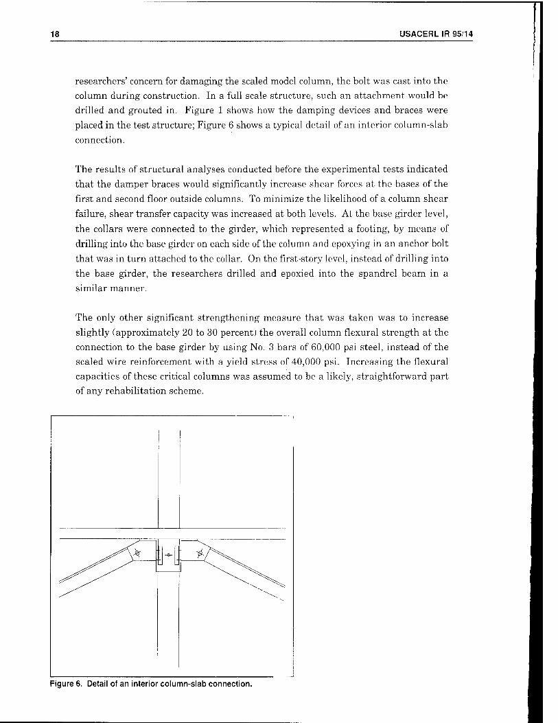
researchers' concern for damaging the scaled model column, the bolt was cast into the
column during construction. In a full scale structure, such an attachment would be
drilled and grouted in. Figure 1 shows how the damping devices and braces were
placed in the test structure; Figure 6 shows a typical detail of an interior column-slab
connection.
The results of structural analyses conducted before the experimental tests indicated
that the damper braces would significantly increase shear forces at the bases of the
first and second floor outside columns. To minimize the likelihood of a column shear
failure, shear transfer capacity was increased at both levels. At the base girder level,
the collars were connected to the girder, which represented a footing, by means of
drilling into the base girder on each side of the column and epoxying in an anchor bolt
that was in turn attached to the collar. On the first-story level, instead of drilling into
the base girder, the researchers drilled and epoxied into the spandrel beam in a
similar manner.
The only other significant strengthening measure that was taken was to increase
slightly (approximately 20 to 30 percent) the overall column flexural strength at the
connection to the base girder by using No. 3 bars of 60,000 psi steel, instead of the
scaled wire reinforcement with a yield stress of 40,000 psi. Increasing the flexural
capacities of these critical columns was assumed to be a likely, straightforward part
of any rehabilitation scheme.
Figure 6. Detail of an interior column-slab connection.

USACERL IR 95/14 19
3 Test Program
Following the completion of model construction and appropriate concrete curing time,
the model was placed on the USACERL shaking table in early 1994. Researchers
added lead ingots, constructed a separate steel emergency support structure (for use
in the event of a catastrophic collapse), and installed test instrumentation.
Approximately 75 channels of data were recorded in each test. Instrumentation
included longitudinal and lateral accelerations and displacements of the shaking table,
base girder, and each floor; damper displacements; damper brace force; damper
temperature change (in selected dampers); and reinforcement strains in key column
and slab locations.
Earthquake testing was conducted using two different sets of viscoelastic dampers
from 3M, as well as with no dampers in place. 3M engineers fabricated one set of
dampers for the desired degree of added damping. They fabricated the second set of
dampers with half the volume of damping material of the first set. Prior to the
earthquake testing, representative samples of the two sizes of dampers that had been
fabricated were tested in static and cyclic tests, to verify theoretical damper
characteristics and ensure sound fabrication. All earthquake testing was conducted
with the steel collars in place, so that damper effects could be isolated and analyzed.
Before any earthquake simulations were conducted, researchers determined the modal
(first three modes) frequencies and equivalent viscous damping of the undamaged
structure in four different states: with no dampers or braces installed, with solid steel
braces installed, with the small dampers installed in braces, and with the large
dampers installed in braces. Two methods of determining the dynamic characteristics
were used. First, a simple "pullback" test was used, in which a weight and pulley
system was used to pull the structure laterally through an attachment at the top floor
level; the weight was suddenly released. After the release of the weight, structural
motions were recorded, from which modal responses and damping were analyzed. This
method relies on the structure's displacing in a manner that is dominated by its first
mode. Second, the shaking table was used to input white noise into the model. By
examining acceleration transfer functions between floors of the model, it was possible
to determine the first three modes of response. After the white noise test, the table
would be used to excite the structure with a sine wave input at its already-determined
first mode response frequency. Researchers would then shut the table off and measure

20 USACERL IR 95/14
the decay of the induced structural motion, from which equivalent viscous damping
could be determined, using logarithmic decrement calculations.
After some trials with the pullback tests, researchers abandoned them. The shaking
table tests were more precise and better-controlled. In addition, when dampers were
installed, the damping ratio was so high that the structure would not oscillate during
the pullback tests. It is also important to note that measuring the dynamic
characteristics became far more difficult during the shaking table tests. The high
degree of damping in the structure greatly broadened the transfer function band-
widths; peak response frequencies were quite difficult to identify.
For the earthquake tests with dampers installed in the model, which were conducted
before any earthquake tests without dampers were conducted, two characteristic
earthquake records were used. The first was the El Centro site record from the 18
May 1940, Imperial Valley, CA, earthquake. The second was the Taft site record from
the 21 July 1952, Kern County, CA, earthquake. The two earthquake records differ
significantly, in terms of peak amplitudes and frequency contents. Figures 7 and 8
show the two records with their time scales compressed to 1A/3 of full scale. (This time
scale was used for all earthquake simulations.) To equate the energy contents of the
two records for the earthquake simulations, the researchers used the ratio of the
spectrum intensities (Housner, 1959) of the two time-scaled records. This process
resulted in a need to multiply the Taft motion amplitudes by a factor of 2.1 to
incorporate the same energy content as the El Centro record.
Researchers conducted a series of low level earthquake simulations with the small
dampers in place. The simulations were run with base acceleration amplitudes of 1,
10, and 25 percent of the El Centro acceleration record; and at 2.1, 21, and 52.5
percent of the Taft acceleration record. Then the structure was tested for the same
earthquake records with large dampers installed. (One "mixed damper" test was also
run with large dampers on the first floor and small dampers on the upper two floors.)
After each earthquake simulation, the dynamic characteristics were determined using
the previously described white noise and sine decay tests, and the model was checked
visually for cracking or other deterioration. The measured dynamic characteristics
indicated how the structure was deteriorating under testing; as it softened due to
cracking of the concrete, the fundamental frequency decreased.
At the conclusion of the low-level tests, little, if any, damage had occurred in the
model. Higher level earthquake simulations were then conducted using the large
dampers. The larger dampers were the ones of original design configuration; their
anticipated stiffness and damping characteristics were tuned to the structure.

USACERL IR 95/14 21
c o
aj o <
10 15 20 Time (sec)
25 30
„j
Figure 7. Time-scaled record from the El Centra earthquake.
"^PffS^^^^
Compressed Time Scale
15 Time (see)
20 25 30
Figure 8. Time-scaled record from the Taft earthquake.

22 USACERL IR 95/14
The higher level earthquake simulations were run at acceleration amplitudes of 10,
25, 50, 75, 100, 125, 150, 200, and 250 percent of the El Centro acceleration record; and
at acceleration amplitudes of 21, 52.5, 105, 157.5, 210, 262.5, 315, and 420 percent of
the Taft acceleration record. Because the higher level El Centro simulations included
ground displacements exceeding the nominal ± 2-3/8-in. horizontal motion capacity of
the shaking table, the 200-percent record was run with a 0.2 Hz high pass filter, while
the 250-percent record was run with a 0.5 Hz high pass filter. This filtering of the
earthquake record removed the lower frequency, larger displacements in the table
motion.
After completing these earthquake simulations, the testing with dampers was
terminated. The tests had reached both the displacement limits of the shaking table
and the as-designed shear displacement limits of the dampers.
Following the completion of the tests with dampers installed, researchers removed the
dampers from the braces in the structure. Subsequent tests were then run without
dampers; the collars that were used to attach the dampers to the columns were left in
place. Earthquake simulations were then run on the undamped, unbraced structure.
The simulations included the same 25, 50, 75, 100, 125, 150, and 200-percent El
Centro records that were used in the damper tests. Tests were concluded after the
200-percent El Centro simulation, when structural failure occurred. No Taft
earthquake simulations of the undamped and unbraced structure were included in the
test program.

USACERL IR 95/14 23
4 Preliminary Observations and Future Work
While researchers have not yet performed detailed analysis of the experimental data,
a few basic observations can be made.
When the testing began, a spurious oscillatory motion occurred in one of the six
horizontal actuators that drive the shaking table, inducing torsion into the model
briefly. Minor cracking of the floor slabs and spandrel beams occurred during the
malfunction. At the time of the malfunction, no data acquisition channels were
activated. However, a thorough check of all components of the structure revealed that
no serious damage had occurred.
Initial white noise tests of the structure without braces or dampers showed a
fundamental frequency of approximately 1.8 Hz. Based on logarithmic decrement
measurements of the acceleration response decay after table shutoff, the baseline
structure had an equivalent viscous damping factor of approximately 0.07 of critical
damping. With the large dampers in place, the first mode frequency ranged between
3.05 and 3.56 Hz, for an average of about 3.3 Hz. The equivalent viscous damping
based on the logarithmic decrement approached 20 percent of critical damping.
Preliminary indications are that the model with dampers sustained only minimal
damage through the 150-percent El Centro earthquake simulation (peak ground
acceleration (PGA) ~ 0.55 g). The white noise tests following this earthquake test
showed a fundamental frequency that was virtually unchanged from the initial white
noise tests. Visual checks of the model showed only minor additional hairline
cracking.
During the 150-percent El Centro earthquake test, the largest interstory drift was
measured as 0.45 in. (1.1 percent), and it occurred in the second story. The total drift
was 1.17 in. (1.0 percent). The maximum base shear experienced during the test was
34.6 kips; the total model weight, neglecting the base girder, was approximately 54.7
kips. Figures 9 and 10 show third floor displacement and base shear response
histories, respectively. Tables 1 through 4 show representative tables of data from the
test.

24 US ACER L IR 95/14
~1
- TOO
~ I (MI
£ -.».(III
'. I.(HI
"fcj- o.oo S -i.oi)
i. -2.00
-n -.1.00 00
150';;, I-.I (Viiim
ty.
Ai\%V'^\l\l\jv^"
Nil l\llll|K'IS
III I 5 .'0
Time C-lVl 30
'I.I
'- 3
E 2
_\ I
S- i) 5 -i .Ü -2
I -1 *-l
l50%GICcnlio
f[li/l~.\,|^J'if.\„n,^/vWv,J—_Y\\,
-5 II) 15 20
linn- (sec)
I Slill'l):iiii|icrä 1
25 30
7.50
5.0(1
2.50
0.00
-2.5(1
-5.00
-7.50
200% I.UCcnliu
^Y^-AN\/W^
If) 15 20
Time (sec)
No Dnm|w:rT;
25 30
Q
'1.00
3.00
2.00
1.00
0.00
-1.00
-2.00
-3.00
-I.OI)
\^M\AM^h^-J^. -,„
200';; 1:1 C cnlro
.. & iri3:ill |K:rs 1
15 20 Tinic (sec)
25 30
Figure 9. Third floor displacement response histories.

USACERL IR 95/14 25
.''5 n
.'on ä. |S|»
22 llt.d
* S(l ■u (I.I) w -5.0 Ü -II).II m -I.VI)
-20.1) -25.0
50.1) '1(1.0
^ M).{)
2 20.0 u 10.0 2 o.o £ -10.0 K -20.0
cS -30.0 -'10.0 -50.0
I5<)';M;KVI>IIU
^ff-JWtj) |l''W^A'VVv- '(!■ f ^ ■>" If "^
10 15 Time (sec)
20
No D;mi|icis
25 30
I5l)%lil Ccnlro
I III •"''fIIII \M1'^IH^^^W^'^^v^-wvv-^r-/-
rSiiin* uliijicis
II) 15 20 'I hue (sec)
25 30
2(K)*l:ICcii!iii
^Ä^Wv^VvVv^
No D:im]>crs
10 15 20 Time (sec)
25 30
500 40.0
D- 30.0 20.0 10.0 0.0
-10.0
n CQ
-20.0 -30.0 -'10.0 -50.0
2U()% El Cenlio
VW-^-'^/Ww-^ -
10 15 20 Time (sec)
I Sliir Damnos 1
25 .10
Figure 10. Base shear response histories.

26 USACERL IR 95/14
It is important to note that corresponding El Centro and Taft earthquake tests were
run sequentially, so, prior to the 150-percent El Centro test, the model had sustained
the El Centro tests through the 100-percent level and the Taft tests through the 210-
percent level. Maximum results of the Taft tests performed with the stiff dampers in
place can be found in Tables 5 through 8.
The preliminary data review indicates that the model with dampers began to sustain
discernable damage in the 200-percent El Centro earthquake test (PGA = 0.86 g). The
white noise tests following this earthquake test showed a fundamental mode frequency
of approximately 2.88 Hz, showing some reduction in stiffness. Visual checks of the
model showed additional hairline cracking had occurred. Most of this cracking was
confined to flexural cracking in the floor slabs and minor torsional cracking of the
spandrel beams at the interfaces with the columns. During the 200-percent El Centro
earthquake test, the largest interstory drift was measured as 0.88 in. (2.2 percent),
again occurring in the second story. The total drift was 2.04 in. (1.7 percent). The
maximum base shear experienced during the test was 44.2 kips. Again, Figures 9 and
10 show third floor displacement and base shear response histories, respectively.
Tables 1 through 4 show representative tables of data from the test.
Following the conclusion of the earthquake tests of the structure with dampers, the
dampers were removed from the model, although the collars were left intact. For the
earthquake tests without dampers, only the El Centro record was used. An initial
white noise test showed a first mode frequency of approximately 1.56 Hz, versus the
original 1.8 Hz. The model had softened and its measured damping had increased,
indicating damage to the structure had accrued during the preceding earthquake simulation tests.
Table 1. Maximum absolute acceleration (g) with and without stiff dampers-El Centro.
Earthquake Test Base Girder 1st Story 2nd Story 3rd Story
50% El Centro (w/dampers) 0.228 0.224 0.261 0.306
50% El Centro (no dampers) 0.212 0.213 0.229 0.178
100% El Centro (w/dampers) 0.408 0.397 0.475 0.598
100% El Centro (no dampers) 0.407 0.424 0.493 0.402
150% El Centro (w/dampers) 0.553 0.567 0.690 0.866
150% El Centro (no dampers) 0.563 0.640 0.602 0.472
200% El Centro (w/dampers) 0.858 0.779 0.959 1.247
200% El Centro (no dampers) 0.983 0.862 0.798 0.675

USACERL IR 95/14 27
Table 2. Maximum relative displacement (in.) with and without stiff
Earthquake Test 1st Story 2nd Story 3rd Story
50% El Centra (w/dampers) 0.124 0.255 0.346
50% El Centra (no dampers) 0.226 0.564 0.816
100% El Centra (w/dampers) 0.252 0.555 0.761
100% El Centra (no dampers) 0.943 1.591 2.033
150% El Centra (w/dampers) 0.412 0.847 1.134
150% El Centra (no dampers) 0.687 1.838 2.566
200% El Centra (w/dampers) 0.640 1.472 1.970
200% El Centra (no dampers) 0.862 3.897 6.814
Table 3. Maximum story shear (kips) with and without stiff dampers-El Centro.
Earthquake Test 1st Story 2nd Story 3rd Story
50% El Centro (w/dampers) 13.225 9.717 5.293
50% El Centro (no dampers) 5.180 4.263 3.092
100% El Centro (w/dampers) 23.707 18.553 10.360
100% El Centro (no dampers) 11.033 9.356 6.968
150% El Centro (w/dampers) 34.636 26.774 15.007
150% El Centro (no dampers) 16.987 14.414 9.811
200% El Centro (w/dampers) 44.219 37.108 21.592
200% El Centro (no dampers) 20.709 17.566 11.694
Table 4. Maximum inter-story displacement (in.) with and without stiff
Earthquake Test 1st Story 2nd Story 3rd Story
50% El Centro (w/dampers) 0.124 0.139 0.096
50% El Centro (no dampers) 0.226 0.353 0.257
100% El Centro (w/dampers) 0.252 0.308 0.219
100% El Centro (no dampers) 0.943 0.710 0.541
150% El Centro (w/dampers) 0.412 0.453 0.306
150% El Centro (no dampers) 0.687 1.209 0.949
200% El Centro (w/dampers) 0.639 0.883 0.522
I 200% El Centro (no dampers) 0.864 3.076 2.967

28 USACERLIR 95/14
Table 5. Maximum absolute acceleration (g) with stiff dampers-Taft.
Earthquake Test Base Girder 1st Story 2nd Story 3rd Story
21%Taft(w/dampers) 0.046 0.046 0.036 0.051
52.5% Taft (w/dampers) 0.099 0.096 0.066 0.128
100% Taft (w/dampers) 0.175 0.166 0.203 0.233
157.5% Taft (w/dampers) 0.309 0.253 0.305 0.357
210% Taft (w/dampers) 0.414 0.348 0.425 0.489
262.5% Taft (w/dampers) 0.522 0.436 0.524 0.643
315% Taft (w/dampers) 0.628 0.530 0.562 0.722
420% Taft (w/dampers) 0.888 0.695 0.770 1.072
Table 6. Maximum story shear kips) with stiff dampers-Taft.
Earthquake Test 1st Story 2nd Story 3rd Story
21% Taft (w/dampers) 2.199 1.494 0.886
52.5% Taft (w/dampers) 4.869 3.388 2.217
100% Taft (w/dampers) 9.544 6.465 2.871
157.5% Taft (w/dampers) 15.237 11.671 6.186
210% Taft (w/dampers) 19.693 16.368 8.463
262.5% Taft (w/dampers) 24.764 20.698 11.135
315% Taft (w/dampers) 28.583 22.451 12.509
420% Taft (w/dampers) 38.715 31.795 18.568
Table 7. Maximum relative displacement (in.) with stiff dampers-Taft.
Earthquake Test 1st Story 2nd Story 3rd Story
21% Taft (w/dampers) 0.025 0.051 0.076
52.5% Taft (w/dampers) 0.057 0.116 0.164
100% Taft (w/dampers) 0.120 0.241 0.320
157.5% Taft (w/dampers) 0.199 0.397 0.525
210% Taft (w/dampers) 0.268 0.575 0.761
262.5% Taft (w/dampers) 0.359 0.757 1.002
315% Taft (w/dampers) 0.425 0.891 1.172
420% Taft (w/dampers) 0.662 1.414 1.844
USACERLIR95/14 29
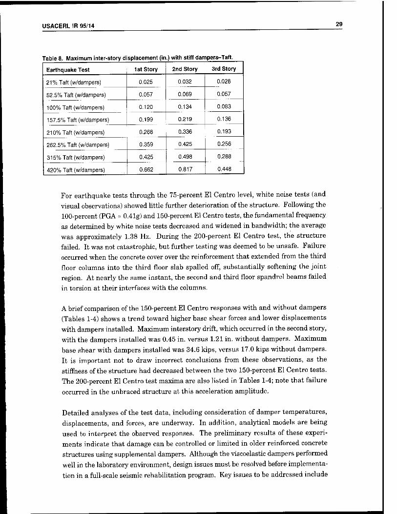
Table 8. Maximum inter-story displacement (in .) with stiff dampers-Taft.
Earthquake Test 1st Story 2nd Story 3rd Story
21%Taft(w/dampers) 0.025 0.032 0.028
52.5% Taft (w/dampers) 0.057 0.069 0.057
100% Taft (w/dampers) 0.120 0.134 0.083
157.5% Taft (w/dampers) 0.199 0.219 0.136
210% Taft (w/dampers) 0.268 0.336 0.193
262.5% Taft (w/dampers) 0.359 0.425 0.256
315% Taft (w/dampers) 0.425 0.498 0.288
420% Taft (w/dampers) 0.662 0.817 0.448
For earthquake tests through the 75-percent El Centro level, white noise tests (and
visual observations) showed little further deterioration of the structure. Following the
100-percent (PGA = 0.41g) and 150-percent El Centro tests, the fundamental frequency
as determined by white noise tests decreased and widened in bandwidth; the average
was approximately 1.38 Hz. During the 200-percent El Centro test, the structure
failed. It was not catastrophic, but further testing was deemed to be unsafe. Failure
occurred when the concrete cover over the reinforcement that extended from the third
floor columns into the third floor slab spalled off, substantially softening the joint
region. At nearly the same instant, the second and third floor spandrel beams failed
in torsion at their interfaces with the columns.
A brief comparison of the 150-percent El Centro responses with and without dampers
(Tables 1-4) shows a trend toward higher base shear forces and lower displacements
with dampers installed. Maximum interstory drift, which occurred in the second story,
with the dampers installed was 0.45 in. versus 1.21 in. without dampers. Maximum
base shear with dampers installed was 34.6 kips, versus 17.0 kips without dampers.
It is important not to draw incorrect conclusions from these observations, as the
stiffness of the structure had decreased between the two 150-percent El Centro tests.
The 200-percent El Centro test maxima are also listed in Tables 1-4; note that failure
occurred in the unbraced structure at this acceleration amplitude.
Detailed analyses of the test data, including consideration of damper temperatures,
displacements, and forces, are underway. In addition, analytical models are being
used to interpret the observed responses. The preliminary results of these experi-
ments indicate that damage can be controlled or limited in older reinforced concrete
structures using supplemental dampers. Although the viscoelastic dampers performed
well in the laboratory environment, design issues must be resolved before implementa-
tion in a full-scale seismic rehabilitation program. Key issues to be addressed include

30 USACERL IR 95/14
damper sizing and placement, ambient temperature control, damper proof testing, and
appropriate structural detailing. The technology looks promising, and tests of other
damping devices are proposed.

USACERL IR 95/14 31
USACERL DISTRIBUTION
Chief of Engineers ATTN AHN ATTN ATTN
AHN AHN
AHN
CEHEC-IM CEHEC-IM CECC-R
CECW-ED CEMP-ET CERD-L CERD-M
(2) (2)
CECPW 22310-3862 AHN: CECPW-EB-S
US Army Engr Divisions AHN: Library (12) North Pacific Division 97208-2870
ATTN: CENPD-PE-TE
US Army Engr District ATTN: Library (9)
Alaska 99506 Charleston 29402 Los Angeles 90012
Louisville 40201 Memphis 38103 Sacremento 95814 San Francisco 94105 Seattle 98124 St. Louis 63101
CEWES 39180 ATTN: Library
TyndallAFB 32403 AHN: HQAFCESA Program Ofc
Naval Facilities Engr Command AHN: OOCE 20374-5063 ATTN: Pacific Division ATTN: Naval Facilities Engr Service Center 93043-4328
University of Illinois at Urbana-Champaign 61801
ATTN: Engineering Library ATTN: Civil Engineering Department
National Institute of Standards and Technology 20899 ATTN: Earthquake and Engineering Group
Department of Veteran Affairs 20420
ATTN: 087C
Department of Energy 20585 ATTN: Office of Risk Assessment and Technology
General Services Administration 20405 ATTN: Office of Design and Construction (PQSB)
Federal Emergency Management Agency 20472
ATTN: Mitigation Directorate
Department of the Interior 80225 ATTN: Bureau of Reclamation, D-3130
Nuclear Regulatory Commission 20555 ATTN: Mailstop NL/S-217A
US Postal Service 20260-6434 ATTN: 475 L'Enfant Plaza, SW
Department of State 22219 ATTN: Office of Foreign Buildings
Tennessee Valley Authority 37902 ATTN: WT 9C-K
Defense Tech Info Center 22304 ATTN: DTIC-FAB(2)
59 6/95
Langley AFB, VA 23665 AHN: HQAMC/CEE
Scott AFB, IL 62225 ATTN: HQAMC/CEE
Wright-Patterson AFB, OH 45433
ATTN: HQAFMC/CEE
Brooks AFB, TX 76901 ATTN: AFOMS-Health Facilities Division
Fort Sam Houston, TX 78234-6000 ATTN: US Army Medical Command-MCFA
National Science Foundation 22230 Earthquake Hazards Mitigation Directorate
National Center for Earthquake Engineering Research 14260-2200
ATTN: Science and Engineering Library
Earthquake Engineering Research Center 94804-4698
ATTN: University of California at Berkeley
. his publication was reproduced on recycled paper.