seismic performance of rc framed buildings with & … · sap2000. the analysis is performed...
TRANSCRIPT

Seismic Performance of RC Framed Buildings
With & Without Infill Walls
1C. Rajesh
M.Tech-Structural Engineering,
Student at C.M.R College of
Engineering&
Technology,Hyderabad, Telangana,
India
2Dr. Ramancharla Pradeep Kumar
Professor & Director of Earthquake
Engineering Research Centre,
IIIT Hyderabad, India
3Prof. Suresh Kandru
Dept. of Civil EngineeringC. M. R
College of Engineering&
Technology,
Hyderabad, Telangana, India
Abstract--In building construction, RC framed structures are
frequently used due to ease of construction and rapid progress of
work, and generally these frames are filled by masonry infill panels
(or) concrete blocks in many of the countries situated in seismic
regions. Infill panels significantly enhance both stiffness and strength
of frame, it behaves like compression strut between column and beam
and compression forces are transferred from one node to another.
Performance of building in earthquakes (like Bhuj Earthquake)
clearly illustrates that the presence of infill walls has significant
structural implications.
This study gives the overview of performance of RC frame
buildings with and with-out infill walls. Here analyses and designs the
masonry infill walls using equivalent diagonal strut concept in-order to
assess their involvement in seismic resistance of regular reinforced
concrete buildings. Modeled the two different buildings with and
without infill walls and designed it and analysis done for gravity and
seismic loads using software (SAP2000). Comparing the results from
the computerized model analyses for with and without infill structures
as bare-frame and single strut models respectively. We check the
results for total weight of building, time period, base shear, and modal
participation mass ratio and comparison of results.
Keywords: Bare-frame, Infill Walls, Equivalent
Diagonal Strut
I. INTRODUCTION
Reinforced concrete (RC) frame buildings with
masonry infill walls have been widely constructed for
commercial, industrial and multi-family residential uses in
seismic-prone regions worldwide. Masonry infill typically
consists of brick masonry or concrete block walls,
constructed between columns and beams of a RC frame.
These panels are generally not considered in the design
process and treated as non-structural components. In
country like India, Brick masonry infill panels have been
widely used as interior and exterior partition walls for
aesthetic reasons and functional needs. Though the brick
masonry infill is considered to be a non-structural element,
but it has its own strength and stiffness. Hence if the effect
of brick masonry is considered in analysis and design,
considerable increase in strength and stiffness of overall
structure may be observed. Present code, IS 1893(Part-I):
2000 of practice does not include provision of taking into
consideration the effect of infill. It can be understood that if
the effect of infill is taken into account in the analysis and
design of frame, the resulting structure may be significantly
different. Significant experimental and analytical research is
reported in various literatures, which attempts to explain the
behavior of infilled frames. Moreover, infill, if present in all
storeys gives a significant contribution to the energy
dissipation capacity, decreasing significantly the maximum
displacements. Therefore the contribution of masonry is of
great importance, even though strongly depending on the
characteristics of the ground motion, especially for frames
which has been designed without considering the seismic
forces. When sudden change in stiffness takes place along
the building height, the story at which this drastic change of
stiffness occurs is called a soft story. According to IS
1893(Part-I): 2000, a soft story is the one in which the
lateral stiffness is less than 50% of the storey above or
below.
Another important issue is related to the numerical
simulation of infilled frames. The different techniques for
idealizing this structural model can be divided into two local
or micro-models and simplified macro models. The first
group involves the models, in which the structure is divided
into numerous elements to take into account of the local
effect in detail, whereas the second group includes
simplified models based on a physical understanding of the
behavior of the infill panel. In this study the strength and
stiffness of the brick masonry infill is considered and the
brick masonry infill is modeled using diagonal strut. The
diagonal strut has been modeled using software package
SAP2000. The analysis is performed using “Linear static
analysis” for understanding the improvement in stiffness
parameters.
Previous experimental studies also carried out on the
behavior of RC frames with in-fills and the modeling,
analysis of the RC frame with and without in-fills. Stafford-
Smith B [1] used an elastic theory to propose the effective
width of the equivalent strut and concluded that this width
should be a function of the stiffness of the in-fill with
respect to that of bounding frame. By analogy to a beam on
elastic foundation, he defined the dimensionless relative
parameters to determine the degree of frame in-fill
interaction and thereby, the effective width of the strut. Also
defined the formulation of empirical equations for the
calculation of infill wall parameter as strut model like
contact length of strut, effective width of the strut. Holmes
[2] was the first in replacing the infill by an equivalent pin-
jointed diagonal strut. He proposed the modeling of infill
wall as the diagonal strut and finding the effective width and
contact length of the diagonal strut. Das and C.V.R. Murty
[3] carried out non-linear pushover analysis on five RC
frame buildings with brick masonry in-fills. In-fills are
International Journal of Engineering Research & Technology (IJERT)
IJERT
IJERT
ISSN: 2278-0181
www.ijert.orgIJERTV3IS100280
(This work is licensed under a Creative Commons Attribution 4.0 International License.)
Vol. 3 Issue 10, October- 2014
281

found to increase the strength and stiffness of the structure,
and reduce the drift capacity and structural damage. In-fills
reduce the overall structure ductility, but increase the overall
strength. Building designed by the equivalent braced frame
method showed better overall performance. Amato et al.
[4]discussed the mechanical behavior of single storey-single
bay in-filled frames performed detailed numerical
investigation on in-filled meshes has proved that in the
presence of vertical loads it is possible that a strong
correlation between the dimension of the equivalent
diagonal strut model and a single parameter, which depends
on the characteristics of the system. V.K.R.Kodur et al.
[5]considered a three storey RC frame building models for
the analysis. These RC frames were analyzed for three cases
i) Bare frame ii) Infilled frame iii) Infilled frame with
openings. Based on the analysis results they found that Base
shear of infilled frame is more than infilled frame with
openings and bare frame. Time period of infilled frame is
less as compare to infilled frame with openings and bare
frame. The natural frequency of infilled frame is more as
compare to infilled frame with openings and bare frame.
Haroon Rasheed Tamboli [6]considered the bare frame and
infill model structures and performs the seismic analysis to
see the variation in both the structures. His paper says that
in presence of infill wall it affects the seismic behavior of
frame structure to large extent and the infill will increase the
strength and stiffness of structure. A.Mohebkhah et al. [7]
performed kinds of numerical modeling strategies to
stimulate the in-plane non-linear static behavior of infilled
frames with openings with micro and macro modeling.
Alsoanalyzed the model of infill frame as three-strut model
and performed pushover analysis to check the capability of
structures during non-linear analysis in which three-strut
model shows more strength and stiffness during the strong
ground motion and perform well when stiffness of infill wall
is considered. Neelima Patnala VS and Pradeep Kumar
Ramancharla [8]considered three sets of 2D ordinary
moment resisting frames with and without unreinforced
masonry infill walls (with and without openings) are
considered. Applied Element Method is used to model the
frames and nonlinear static pushover analysis is carried out
to obtain the capacity curves. It is observed that the strength
of the frame with infill is 10 times more than the ordinary
bare frame, ductility of the frame increases with the addition
of the infill walls. increase in number of storeys, the
strength of the bare frame increases, obviously, whereas the
strength of the frame with infill decreases it can be said that
the difference in behavior of bare frame should not only be
verified on a single storey but to be checked with different
number of stories.
Methodology of the Work
The methodology worked out to know the performance
of the buildings with and without infill walls during the
analysis. Considering two buildings of and modeled as bare-
frame and with infill walls which infill walls are modeled as
equivalent diagonal strut model in the frame. Perform the
linear static analysis for all the model buildings using
SAP2000 software for both gravity and seismic load
analysis and comparative study is taken out from the
analysis. Comparison is taken drawn out on all the aspects
of the performance of the buildings individually.
II. MODELING & ANALYSIS OF BARE-FRAME
BUILDINGS
Considered two buildings of G+5 & G+9 storeys
having same floor height and similar properties of the
structures. Both the buildings are modeled as bare-frame
i.e., buildings without considering infill walls between the
vertical and horizontal elements of the building. These are
analyzed for gravity loads and seismic loads in the software
as per IS 1893(Part-1):2002 condition of analysis.
A. Preliminary Data
To analyze the gravity and seismic load performance of
the building we considered two different building of
different heights as G+5 and G+9 storeys RC framed
buildings of same storey levels. The general parameters
required for the modeling of the two buildings has the same
parameter are as follows:
Type of frame :Special RC moment
resisting frame fixed at the base
Seismic zone :V
Number of storeys :G+5 & G+9
Floor height :3.5 m
Plinth height :1.5 m
Depth of Slab :150 mm
Spacing between frames :5m along both
directions
Live load on floor level :4 kN/m2
Live load on roof level :1.5 kN/m2
Floor finish :1.0 kN/m2
Terrace water proofing :1.5 kN/m2
Materials :M 20 concrete, Fe 415 steel and
Brick infill
Thickness of infill wall :250mm (Exterior walls)
Thickness of infill wall :150 mm (Interior walls)
Density of concrete :25 kN/m3
Density of infill :20 kN/m3
Type of soil :Medium
Response spectra :As per IS 1893(Part-
1):2002
Damping of structure :5 %
**Live load on floor level and roof level are taken from
IS-875 (Part-) considered RC framed buildings as
commercial usage.
B. Member and Material Properties
Dimensions of the beams and columns are determined
on the basis of trial and error process in analysis of
SAP2000 by considering nominal sizes for beams and
columns and safe sizes are as show in the table below.
International Journal of Engineering Research & Technology (IJERT)
IJERT
IJERT
ISSN: 2278-0181
www.ijert.orgIJERTV3IS100280
(This work is licensed under a Creative Commons Attribution 4.0 International License.)
Vol. 3 Issue 10, October- 2014
282

Table 1: Properties of Bare – Frame, Strut Model Buildings
Type of
Analysis Model
Gravity Load
Building
Seismic Load
Building
BEAM
(m)
COL.
(m)
BEAM
(m)
COL.
(m)
G+5
storey
Building
Bare-
frame
0.40 x
0.40
0.50
x
0.50
0.50x0
.50
0.60 x
0.60
Single-
strut
0.40 x
0.40
0.55
x
0.55
0.45 x
0.45
0.60 x
0.60
G+9
storey
Building
Bare-
frame
0.50 x
0.50
0.60
x
0.60
0.55 x
0.55
0.70 x
0.70
Single-
strut
0.50 x
0.50
0.60
x
0.60
0.55 x
0.55
0.65 x
0.65
Material properties of the building are like M20 grade
of concrete, FE415 steel and 13800 N/mm2 of modulus of
elasticity of brick masonry in the buildings.
C. Load Calculations
In this dead and live loads due to slab is transferred to
beams using yield line theory as per IS CODE- SP-24-
(1983) bending moments in the beams may be determined
with sufficient accuracy by assuming that the loading is
equivalent to a uniform load per unit length of the beam is
as follows:
On the short span UDL = 𝑊𝑙𝑥
3
On the long span UDL = 𝑊𝑙𝑥
6 3 −
𝑙𝑥
𝑙𝑦
2
Where,
lx = Shorter span,
ly= Longer span
W = Load per unit length
Figure 1: Load Carried By Supported Beams
The distribution of loads are calculated and found as shown
in the table.
Table 2: Slab loads on beam using Yield line theory
Type of
load Position
DL of
slab
LL of
slab
DL of
Wall
Units (kN) (kN) (kN)
Load on
roof
beams
Exterior
beams 10.416 2.5 6.0
Interior
beams 20.832 5.0 0
Loads on
Floor
beams
Exterior
beams 7.916 6.66 15.5
Interior
beams 15.83 13.33 9.3
Loads on
Plinth
beams
Exterior
beams 0 0 15.5
Interior
beams 0 0 9.3
After modeling the buildings the plan, elevation and
3D-views are show in the figures below. Using the load
combinations for gravity and seismic loads as per IS
1893(Part-1):2002, clause 6.3.1.2 analyzed the G+5 & G+9
storey bare-frame models using the software and drawn out
the results like total weight, time period, base shear and
modal participation mass ratio of the two buildings. Also for
finding the results of base shear and time period manual
process is also done using Equivalent Static Method. The
results can be seen in the tables.
Figure 2: Plan of G+5 & G+9 storey building of all models
International Journal of Engineering Research & Technology (IJERT)
IJERT
IJERT
ISSN: 2278-0181
www.ijert.orgIJERTV3IS100280
(This work is licensed under a Creative Commons Attribution 4.0 International License.)
Vol. 3 Issue 10, October- 2014
283
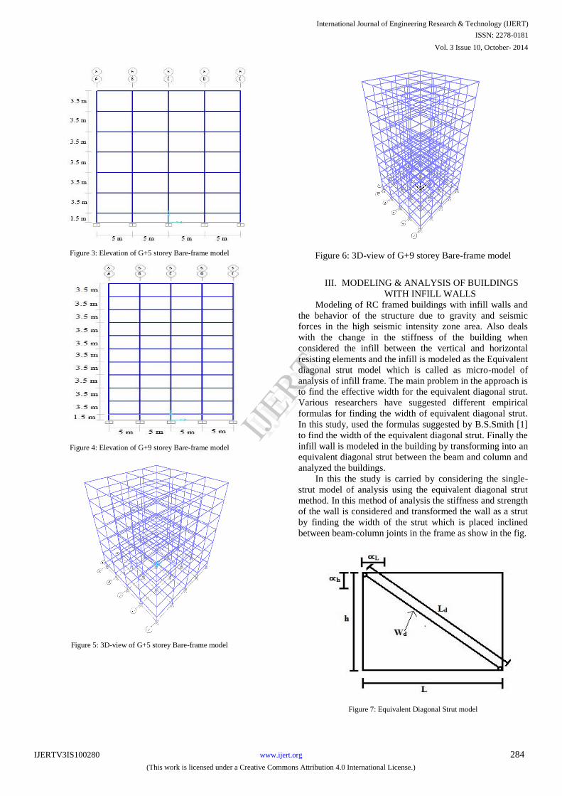
Figure 3: Elevation of G+5 storey Bare-frame model
Figure 4: Elevation of G+9 storey Bare-frame model
Figure 5: 3D-view of G+5 storey Bare-frame model
Figure 6: 3D-view of G+9 storey Bare-frame model
III. MODELING & ANALYSIS OF BUILDINGS
WITH INFILL WALLS
Modeling of RC framed buildings with infill walls and
the behavior of the structure due to gravity and seismic
forces in the high seismic intensity zone area. Also deals
with the change in the stiffness of the building when
considered the infill between the vertical and horizontal
resisting elements and the infill is modeled as the Equivalent
diagonal strut model which is called as micro-model of
analysis of infill frame. The main problem in the approach is
to find the effective width for the equivalent diagonal strut.
Various researchers have suggested different empirical
formulas for finding the width of equivalent diagonal strut.
In this study, used the formulas suggested by B.S.Smith [1]
to find the width of the equivalent diagonal strut. Finally the
infill wall is modeled in the building by transforming into an
equivalent diagonal strut between the beam and column and
analyzed the buildings.
In this the study is carried by considering the single-
strut model of analysis using the equivalent diagonal strut
method. In this method of analysis the stiffness and strength
of the wall is considered and transformed the wall as a strut
by finding the width of the strut which is placed inclined
between beam-column joints in the frame as show in the fig.
Figure 7: Equivalent Diagonal Strut model
International Journal of Engineering Research & Technology (IJERT)
IJERT
IJERT
ISSN: 2278-0181
www.ijert.orgIJERTV3IS100280
(This work is licensed under a Creative Commons Attribution 4.0 International License.)
Vol. 3 Issue 10, October- 2014
284

In modeling the equivalent diagonal strut
major part is to find the effective width of the
strut in which it depend on length of contact
between wall and column and between wall
and beam. Stafford smith developed the
formulations for αh and αL on the basis of
beam on an elastic foundation. Hendry
proposed the equation to find the equivalent
diagonal strut width. The following equations
are proposed to determine αh and αL, which
depend on the relative stiffness of the frame
and infill walls, and on the geometry of panel.
∝ℎ=𝜋
2
4 𝐸𝑓𝐼𝑐ℎ
𝐸𝑚 t sin2θ
4
∝𝐿=𝜋
2
4 𝐸𝑓𝐼𝑏ℎ
𝐸𝑚 t sin2θ
4
Where,
Em and Ef = Elastic modulus of the masonry wall
and frame material (i.e., concrete), respectively.
L, h, t = Length, height and thickness of the
infill wall, respectively.
Ic, Ib = Moment of inertial of column and the
beam of structure, respectively.
𝜃 = tan−1 ℎ
𝐿 = angle of inclination of diagonal
strut.
The equation to determine the equivalent or
effective strut width (wd), length (Ld) and area of strut
( Ad), where the strut is assumed to be
subjected to uniform compressive stress.
wd =1
2 ∝ℎ
2 +∝𝐿2
𝐿𝑑 = ℎ2 + 𝐿2
𝐴𝑑 = 𝑡 wd
By using these formulas the effective width (wd),
length (Ld) and area (Ad) of the diagonal strut is
determined.
Consider the same parameters of bare frame modeled
buildings of G+5 & G+9 storey building and its
loading. Here bare frame model is changed into single-
strut model by considering the stiffness of the masonry
infill wall which acts as a rigid element. The effective
width, length and area of the strut, are calculated for
both the buildings separately.
Table 3 Parameters of G+5 storey Diagonal Strut Models
Parameters Data Units
Grade of concrete 20 MPa
Modulus of elasticity of concrete Ef 22360.68 MPa
Modulus of elasticity of brick
masonry Em 13800 MPa
Size of beam (Depth x Width) 0.50 x 0.50 m
Size of column 0.60 x 0.60 m
Moment of inertia of beam Ib 5.2 x 10⁻³ m4
Moment of inertia of column Ic 10.8 x 10⁻³ m4
Thickness of External Infill wall te 0.25 m
Thickness of internal infill wall ti 0.15 m
Length of masonry 4.4 m
Height of masonry h
Floor level 3.0 m
Plinth level 1.0 m
Angle of inclination
of strut 𝜃 =
tan−1 ℎ𝑚
𝐿𝑚
Floor level 34.28° Degrees
Plinth level 12.80° Degrees
The width of the single strut building is shown
in table below.
Table 4: Calculation of Width of Diagonal of Single – struts
Level Strut
type ∝h (m)
∝L (m)
Wd
(m)
Ld
(m)
Ad
(m2)
Floor
Ext.
wall 1.53 1.4 1.04 5.33 0.26
Int.
wall 1.74 1.59 1.18 5.33 0.18
Plinth
Ext.
wall 1.41 1.7 1.10 4.51 0.28
Int. wall
1.6 1.93 1.25 4.51 0.19
From the above table Wd the value of width of the strut
placed diagonally between the beam and column joints.
Using the width of the strut and length of the strut we
modeled the single-strut model building with the basic
parameters and loading on beams and columns are same as
the bare-frame G+5 & G+9 storey building. So after
modeling the building with external strut and internal strut
we can see the model of buildings as shown in fig. below.
International Journal of Engineering Research & Technology (IJERT)
IJERT
IJERT
ISSN: 2278-0181
www.ijert.orgIJERTV3IS100280
(This work is licensed under a Creative Commons Attribution 4.0 International License.)
Vol. 3 Issue 10, October- 2014
285
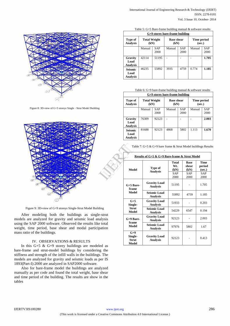
Figure 8: 3D-view of G+5 storeys Single - Strut Model Building
Figure 9: 3D-view of G+9 storeys Single-Strut Model Building
After modeling both the buildings as single-strut
models are analyzed for gravity and seismic load analysis
using the SAP 2000 software. Observed the results like total
weight, time period, base shear and modal participation
mass ratio of the buildings.
IV. OBSERVATIONS & RESULTS
In this G+5 & G+9 storey buildings are modeled as
bare-frame and strut-model buildings by considering the
stiffness and strength of the infill walls in the buildings. The
models are analyzed for gravity and seismic loads as per IS
1893(Part-I):2000 are analyzed in SAP2000 software.
Also for bare-frame model the buildings are analyzed
manually as per code and found the total weight, base shear
and time period of the building. The results are show in the
tables
Table 5: G+5 Bare-frame building manual & software results
G+9 storey bare-frame building
Type of
Analysis Total Weight
(kN)
Base shear
(kN)
Time period
(sec.)
Manual SAP
2000
Manual SAP
2000
Manual SAP
2000
Gravity
Load
Analysis
42114 51195 - - - 1.705
Seismic
Load
Analysis
46235 55892 3935 4759 0.774 1.185
Table 6: G+9 bare-frame building manual & software results
G+9 storey bare-frame building
Type of
Analysis
Total Weight
(kN)
Base shear
(kN)
Time period
(sec.)
Manual SAP
2000
Manual SAP
2000
Manual SAP
2000
Gravity
Load
Analysis
76309 92123 - - - 2.003
Seismic
Load
Analysis
81688 92123 4868 5802 1.113 1.670
Table 7: G+5 & G+9 bare
-
frame & Strut Model buildings Results
Results of G+5 & G+9 Bare-frame & Strut Model
Model
Type of
Analysis
Total
Wt.
(kN)
Base
shear
(kN)
Time
period
(sec.)
SAP
2000
SAP
2000
SAP
2000
G+5 Bare-
frame
Model
Gravity Load
Analysis
51195
-
1.705
Seismic Load
Analysis
55892
4759
1.185
G+5
Single-
Strut
Model
Gravity Load
Analysis
51933
-
0.203
Seismic Load
Analysis
54229
6547
0.194
G+9 Bare-
frame
Model
Gravity Load
Analysis
92123
-
2.003
Seismic Load
Analysis
97976
5802
1.67
G+9
Single-
Strut
Model
Gravity Load
Analysis
92123
-
0.413
International Journal of Engineering Research & Technology (IJERT)
IJERT
IJERT
ISSN: 2278-0181
www.ijert.orgIJERTV3IS100280
(This work is licensed under a Creative Commons Attribution 4.0 International License.)
Vol. 3 Issue 10, October- 2014
286

VI. COMPARISON OF RESULTS
The comparison of results for bare-frame and strut
model buildings are show in the figures, and discussed the
comparison of results are based in the analysis of buildings.
Figure 10: Comparison of Time Period of G+5 storey Buildings
Figure 11: Comparison of Base Shear of G+5 storey Buildings
Figure 12: Comparison of Time Period of G+9 storey Buildings
Figure 13: Comparison of Base Shear of G+9 storey Buildings
Figure 14: Comparison of Modal Participation of Mass Ratio for Gravity Analysis of G+5 storey Models in X-direction
1.705
0.203
1.185
0.194
0
0.5
1
1.5
2
Bare frame Single strut
Tim
e P
eri
od
(Se
c.)
G+5 Storey Models
Comparison of Gravity & Seismic Analysis
Results for Time Period of G+5 Storey Models
Gravity Analysis - Time period
Seismic Analysis - Time period
4759
6547
0
1000
2000
3000
4000
5000
6000
7000
Bare frame
Single strut
Bas
e S
he
ar (
kN)
G+5 Storey Models
Comparison Base shear of G+5
Storey Models
Base shear
2.003
0.413
1.67
0.394
0
1
2
3
Bare frame Single strutTim
e P
eri
od
(Se
c.)
G+9 Storey Models
Comparison of Gravity & Seismic
Anlaysis Results for Time Period of
G+9 storey Models
Gravity Analysis - Time period
Seismic Anlaysis - Time period
5802
8643
0
2000
4000
6000
8000
10000
Bare frame Single strut
Bas
e S
he
ar (
kN)
G+9 Storey Models
Comparison of Base shear of G+9
Storey Models
Base shear
0.717
0.089 0.074
0.3080.244
0.132
0
0.2
0.4
0.6
0.8
Mode 1 Mode 2 Mode3
Mo
dal
Mas
s R
atio
Modes
Comparison of Modal
Participation Mass Ratio for
Gravity analysis of G+5 storey
models in X-directionBare
Single Strut
International Journal of Engineering Research & Technology (IJERT)
IJERT
IJERT
ISSN: 2278-0181
www.ijert.orgIJERTV3IS100280
(This work is licensed under a Creative Commons Attribution 4.0 International License.)
Vol. 3 Issue 10, October- 2014
287

Figure 15: Comparison of Modal Participation of Mass Ratio for Gravity
Analysis of G+5 storey Models in Y-direction
Figure
16: Comparison of Modal Participation of Mass Ratio for
Gravity
Analysis of G+9 storey Models in X-direction
Figure 17: Comparison of Modal Participation of Mass Ratio for Gravity
Analysis of G+9 storey Models in Y-direction
Figure 18: Comparison of Modal Participation of Mass Ratio for Seismic
Analysis of G+5 storey Models in X-direction
Figure 19: Comparison of Modal Participation of Mass Ratio for Seismic
Analysis of G+5 storey Models in Y-direction
Figure 20: Comparison of Modal Participation of Mass Ratio for Seismic Analysis of G+9 storey Models in X-direction
0.717
0.089 0.074
0.308 0.2440.132
0
0.2
0.4
0.6
0.8
Mode 1 Mode 2 Mode 3
Mo
dal
Mas
s R
atio
Modes
Comparison of Modal
Participation Mass Ratio for
Gravity analysis of G+5 storey
models in Y-direction Bare-Frame
Single Strut
0.791
0.089 0.021
0.274 0.306
0.112
0
0.5
1
Mode 1 Mode 2 Mode3
Mo
dal
Mas
s R
ario
Modes
Comparison of Modal
Participation Mass Ratio for
Gravity Analysis of G+9 storey
modals in X-direction Bare
Single Strut
0.791
0.089 0.021
0.274 0.306
0.112
0
0.2
0.4
0.6
0.8
1
Mode 1 Mode 2 Mode3
Mo
dal
Mas
s R
atio
Modes
Comparison of Modal
Participation Mass Ratio for
Gravity Analysis of G+9 storey
modals in Y-direction Bare
0.788
0.061 0.035
0.3130.25
0.133
0
0.2
0.4
0.6
0.8
1
Mode 1 Mode 2 Mode3
Mo
dal
Mas
s R
atio
Modes
Comparison of Modal Participation
Mass Ratio for Seismic Analysis of
G+5 storey modals in X-direction
Bare
0.788
0.061 0.035
0.3130.250
0.133
0
0.2
0.4
0.6
0.8
1
Mode 1 Mode 2 Mode3
Mo
dal
Mas
s R
atio
Modes
Comparison of Modal Participation
Mass Ratio for Seismic Analysis of
G+5 storey modals in Y-direction Bare
Single Strut
0.786
0.0970.018
0.277 0.308
0.113
0
0.2
0.4
0.6
0.8
1
Mode 1 Mode 2 Mode3
Mo
dal
Mas
s R
atio
Modes
Comparison of Modal Participation
Mass Ratio for Seismic Analysis of
G+9 storey modals in X-direction Bare
Single Strut
International Journal of Engineering Research & Technology (IJERT)
IJERT
IJERT
ISSN: 2278-0181
www.ijert.orgIJERTV3IS100280
(This work is licensed under a Creative Commons Attribution 4.0 International License.)
Vol. 3 Issue 10, October- 2014
288

Figure 21: Comparison of Modal Participation of Mass Ratio for Seismic Analysis of G+9 storey Models in Y-direction
VII. CONCLUSION
From the observation of the results it states that
decrease in the time period will leads to increase in the base
shear of the building and also total weight of the building is
less in strut model as compared to bare-frame model
buildings. Strut model buildings show the less time period
and total weight of the building and higher in the base shear
of the building. As if we know time period is inversely
proportional to stiffness, here it is seen that strut model
buildings has less time period than bare-frame buildings
which can say that strut model buildings are more stiffer and
safer during the earthquakes than the bare-frame models.
From the previous earthquakes like Bhuj in 2001 many of
the buildings are collapsed due to the improper analysis and
design of buildings which are analyzed without considering
the stiffness of the walls which leads to the sudden collapse
of the buildings. From this analysis it concludes that strut
model buildings gives better and best performance than
bare-frame model buildings in the high seismic prone areas.
REFERENCES
1. a. Stafford Smith B, Lateral stiffness of infilled frames,
Journal of Structural division, ASCE,88 (ST6), 1962, pp. 183-
199.
b. Stafford Smith B. Behaviour of Square Infilled Frames.
Proceedings of the American Society of Civil Engineers,
Journal of Structural Division, 92, no STI, 381-403, 1966.
c. Stafford Smith B, Carter C. A method of analysis for infill
frames. Proc. Inst. Civil Engineering, 1969.
2. Holmes M. Steel frames with brickwork and concrete
infilling. Proceedings of the Institution of Civil Engineers 19,
1961.
3. A. DAS D AND MURTY C V R, Brick Masonry Infills in
Seismic Design of RC Frame Buildings: Part 2- Behaviour,
The Indian Concrete Journal, 2004.
4. A. AMATO G, CAVALERI L, FOSSETTI M, AND PAPIA
M, Infilled Frames: Influence of Vertical Load on The
Equivalent Diagonal Strut Model, The 14th World
Conference on Earthquake Engineering, Beijing, China, 2008.
5. V.K.R.Kodur, M.A.Erki and J.H.P.Quenneville “Seismic
analysis of infilled frames” Journal of Structural Engineering
Vol.25, No.2, July 1998 PP 95 -102.
6. Haroon Raheed Tamboli and Umesh N.Karadi, Seismic
Analysis of RC Frame Structures With and Without Masonary
Walls, Indian Journal of Natural Sciences, Vol.3/Issue14,
Oct.2012.
7. A.Mohebkhah, A.A.Tanimi, and H.A.Moghadam, A Modified
Three-Strut (MTS) Model for Masonry-InfilledSteel Frames
with Openings, Journal of Seismology and Earthquake
Engineering, Vol.9, No.1,2 , Spring and Summer 2007.
8. Patnala V S Neelima, Ramancharla Pradeep Kumar, Seismic
Behaviour of RC Frame with URM Infill: A Case Study,
International Journal of Education and Applied Research
(IJEAR), Vol.4, Issue Spl-2, Jan-June 2014.
9. Text book: “Earthquake Resistant Design of Structures”, by
Pankaj Agarwal and Manish Shrikhande, PHI Learning
Private Limited, 2013.
10. Text book: “Earthquake Resistant Design of Structures”, by
S.K.Duggal.
11. IS 456, “Plain and Reinforced Concrete-Code of Practice”,
Bureau of Indian Standards, New Delhi, 1993.
12. IS 1893, “Criteria for Earthquake Resistant Design of
Structures-Part-1”: General Provisions and Buildings (Fifth
Revision), Bureau of Indian Standards, New Delhi, 2002.
13. SP-16, Design Aids for Reinforced Concrete to IS: 456-1978,
Bureau of Indian Standards, New Delhi, 1980.
14. SP 24 (1983): Explanatory Handbook on Indian Standard
Code of Practice for Plain and Reinforced Concrete (IS
456:1978, [CED 2: Cement and Concrete].
15. IS 1786 (2008): High strength deformed steel bars and wires
for concrete reinforcement- [CED 54: Concrete
Reinforcement].
16. IS 875-2 (1987): Code of Practice for Design Loads (Other
Than Earthquake) For Buildings And Structures, Part 2:
Imposed Loads [CED 37: Structural Safety].
0.786
0.0970.018
0.277 0.308
0.113
0
0.1
0.2
0.3
0.4
0.5
0.6
0.7
0.8
0.9
Mode 1 Mode 2 Mode3
Mo
dal
Mas
s R
atio
Modes
Comparison of Modal Participation
Mass Ratio for Seismic Analysis of
G+9 storey modals in Y-directionBare
Single Strut
International Journal of Engineering Research & Technology (IJERT)
IJERT
IJERT
ISSN: 2278-0181
www.ijert.orgIJERTV3IS100280
(This work is licensed under a Creative Commons Attribution 4.0 International License.)
Vol. 3 Issue 10, October- 2014
289
