seismic performance based-design of large earth and ...cmgi.cl/publicaciones-web/verdugo/seismic...
TRANSCRIPT

Performance-Based Design in Earthquake GeotechnicalEngineering – Kokusho, Tsukamoto & Yoshimine (eds)
© 2009 Taylor & Francis Group, London, ISBN 978-0-415-55614-9
Seismic performance based-design of large earth and tailing dams
R. VerdugoUniversity of Chile, Chile
ABSTRACT: The actual capability of predicting the seismic performance of earth structures is limited and itis important to recognize that the real application of PBSD in professional practice is still years away. However,it is important to admit that PBSD is attractive and efforts have to be done to make it closer to practitioners. Inthe seismic design of tailings dams there are two main factors that control the liquefaction resistance of tailingssands: density and fines content. Accordingly, test results showing the effect of these two factors are presented.In the case of large earth dams, the use of coarse materials is common because of their good mechanical behavior.However, the evaluation of their properties is difficult due to the lack of equipment to test large particles. Analternative procedure to evaluate mechanical properties of coarse soils is presented. Additionally, the long termdeformations of three large dams are analyzed and an empirical expression to estimate these deformations isproposed.
1 PERFORMANCE BASED SEISMIC DESIGN
In a broad sense performance-based seismic design(PBSD) can be understood as a design criteria whichgoal is the achievement of specified performance tar-gets when the structure is subjected to a defined seis-mic hazard. The specified performance target couldbe a level of displacements, level of stresses, maxi-mum acceleration, mobilized strength, or a limit state,among others. In this respect, the limit state design canbe seen as a particular case of the PBSD, where the per-formance target is the accomplishment of a resistingforce.
The PBSD is being strongly promoted by structuralengineers, probably encouraged by the heavy financiallosses resulting after recent earthquakes. This comesfrom the fact that the main investments in buildingconstruction are the non-structural components andcontents (Astrella & Whittaker, 2004). For example,in the case of office buildings, hotels and hospitalstructures, the investment in structural framing is onlyaround 18, 13 and 8%, respectively; of the total cost(Miranda & Taghavi, 2003). This clearly indicates thatthe fundamental objective of building code provisionsto guaranty structure integrity, in terms of no collapseagainst strong ground motion, is definitely insufficientto be considered a successful seismic behavior to thesociety. Accordingly, efforts are now being conductedto reduce the financial losses associated with thenon-structural components and contents throughout adesign that considers specific performance structuraltargets, such as maximum displacements, maximumaccelerations, or inter-story drift, especially in thoseparts where the main investments are located. Inthis scenario, it seems naturally that building owners
and insurers, among others, should be involved inmaking informed decisions regarding the expectedperformance of the structures.
It is important to recognize that the formal useof performance-based design is definitely less wide-spread in geotechnical engineering than in structuralengineering. Nevertheless, since the 60s the earth-quake geotechnical community is applying methodsof analysis for predicting permanent displacementsin earth structures, which is basically a performancecriterion as opposed to the classical concept of limitequilibrium (Newmark, 1965; Seed 1966, Makdisi &Seed, 1977). In addition, the design of foundationsplaced on granular soils is normally controlled by set-tlements rather than bearing capacity, which is alsoa performance criterion. In this sense, although it isnot formally stated, the performance-based design isreasonably familiar for geotechnical engineers.
Since the middle 90s, geotechnical engineers fromdifferent countries have been promoting the devel-opment and application of PBSD, following to someextend the tendency that is observed in structure seis-mic design. Although some efforts have been orientedto standardize and improve the use of PBSD, as itis now conceived, it is flawed in crucial elements.Our present capability of predicting the mechanicalseismic performance of earth structures inherentlyinvolves an important level of uncertainty. Startingwith the prediction of the seismic event, continuingwith the ability of ground characterization (such asgeometry, heterogeneities, properties) and ending upwith the real skills to model the dynamic soil responsewhen it goes well beyond the linear behavior. Con-sidering these fundamental uncertainties, it is com-monly suggested that PBSD should be conducted on a
41

probabilistic basis, indicating the probability ofexceeding a certain desired performance and the con-fidence of this probability. Unfortunately, the prob-abilistic approach is not accessible for most ofpractitioners and it does not really improve the finaloutcome which is the performance prediction.
Likely the most important issues behind the PBSDare the following:
– The intention of involving stakeholders (owners,insurers and regulators) in the decisions concern-ing the choose of target performances for a earthstructure during and after seismic events, sharingin this way the decision-making process.
– The premise that seismic performance levels canbe predicted analytically, so the cost associatedwith each level of performance can be rationallyevaluated.
In spite of the benefit of involving stakeholders inthe decision-making process of choosing a specific setof performance targets, it is important to be aware ofthe potential problems and consequences associatedwith this idea. To combine appropriately both, com-plex technical solutions and investment decision basedon risk analysis, is also risky. This necessarily intro-duces another source of uncertainty which could beeven more important that the technical uncertainties.This statement is written just when the financial crisisis striking the whole world, and it is strongly influencedby this fact.
On the other hand, the actual capability of pre-dicting the seismic response of earth structures is amore fundamental issue. From a scientific point ofview, there is a reasonable knowledge of soil and rockmechanical behavior that has been incorporated intonumerical models that are basically able to repro-duce a variety of laboratory test results. However, inengineering practice, the real situation is less promis-ing, especially when the earth structures have singulargeometries that need, for example, three dimensionalanalysis, or when several different geotechnical mate-rials are involved, being necessary a deep geotechnicalcharacterization of each one.
In the case of dam engineering, additionally, practi-tioners have to face the geotechnical characterizationof rockfill materials constituted by large size particles.Normally there is a lack of available testing appara-tuses for these coarse materials, therefore geotechnicalproperties have to be estimated to properly desing aearth dam of this type.
In addition, there are several factors that are wellrecognized that affect the stress-strain relationship, butthey are not included in the current models used inpractice. Among these factors, it is possible to indicatethat the most relevant are the following:
– Stress rotations that take place during seismicloading.
– Variation of the intermediate principal stress, σ2.– Seismic pore water pressure generation.– Redistribution of pore water pressure.– Densification due to particle rearrangement.
In this context, the actual capability of predictingthe seismic performance is quite limited. Conse-quently, it is important to recognize that the realapplication of the PBSD in professional practice isyears away, but it is also important to admit that thisdesign criterion is attractive and more efforts have tobe done in order to improve it.
In this paper key geotechnical properties of coppertailings materials are presented, which are necessaryto consider if performance based seismic design iscarried out in tailings dam projects.
For the case of earth dams constructed with coarsematerials, a test procedure using parallel grain sizecurves is proposed to estimate the mechanical prop-erties of the coarse fills. Additionally, the variationof the deformation modulus with time obtained fromthe analysis of measured settlements of three Chileandams is presented. For the application of the perfor-mance based seismic design of earth dams with coarsefills these results are considered relevant.
2 TAILINGS DEPOSITS
2.1 General framework
The waste products resulting from mining operationsare called tailings. Typically in copper, gold and zincmines, the extracted ore is crushed to the size of finesand to clay from where the minerals are recovered.In the case of copper mines it is important to mentionthat, as an order of magnitude, around one percent inweight corresponds to the valuable minerals that areretrieved from the milled ore. Therefore, the miningoperations have to manage large quantities of tailingswhich are around 99 times the weight of the copper,gold or zinc production. In addition, it is necessary tomention that due to the mining processes associated tothe removal of the minerals, the resulting tailings arefully saturated.
In countries with a substantial mining industry,such as Australia, Canada, Chile, Chine, Peru, Poland,South Africa, and USA, among others, the design andconstruction of enormous tailing disposals is a crucialnecessity that has been continuously imposing newgeotechnical challenges. The mining industry gener-ates everyday millions of cubic meters of waste thathas to be disposed safely and inexpensively. In Chile,for instance, there are in operation tailings dams witha height of 150 meters and reservoirs with more thanone thousand million tones of slimes, and there areprojects under construction that will end up with tail-ings dams of 220 meter in high (Valenzuela et al.,1995). This trend indicates that conventional tailings
42

dams with large dimensions in terms of height andextension are accepted solutions for disposing miningwaste products, and the assessment of their mechani-cal stability is one of the main concerns. Additionally,in all those regions with a high seismic activity, the sta-bility and liquefaction resistance requirements are themain issues to be analyzed and satisfied. Furthermore,because all tailings disposals will exist well after themining operation is ended, the seismic stability has tobe ensured for a large period of time after closure ofthe mine.
In spite of these requirements, there are several casehistories associated to the total failure of tailings damsdue to the occurrence of liquefaction. In general, satu-rated deposits of loose cohesionless soils have shownto be susceptible to liquefaction during the occurrenceof earthquakes. This phenomenon has been observedin tailing dams, hydraulic fills, as well as in natu-ral slopes of sandy soils. It is important to bear inmind that a failure of a tailings dam has catastrophicresults from economical and environmental points ofview, and also can be associated with human casual-ties. Consequently, a failure has to be avoided by allmeans, but at the same time it is necessary to keep inmind that over design it is just a waste of resources.
For an appropriate design of conventional tailingsdams that ensures stability at a minimum cost of con-struction, operation and abandon, the conditions ofthe storage site as geomorphology, geology and seis-mic activity of the area have to be considered. On theother hand, the geotechnical properties of the involvedtailings play a predominant role in the selection of themost convenient design. In this paper the liquefactionstrength of tailings materials is discussed at the lightof new experimental data considering a wide range offines content and densities.
2.2 Tailings disposals
Depending on how the tailings are processed, trans-ported, discharged and stored, the resulting tailingsdisposals can be divided in two different systems:thickened tailings (or paste) disposals and conven-tional tailings dams. There are also others procedures,for example, filtered tailings, but they are less useddue to their high cost.
In the case of thickened tailings disposal system,the main goal is to create a self-supporting tailingsmass, so confining dikes can be eliminated or at leastminimised. To accomplish this, the water contentof the initial tailings slurry is reduced as much aspossible prior to discharge by mean of high-densitythickeners, resulting in a tailings deposit of a gently-sloping conical shape, with typical angles between2 to 6 percent. The concept of thickened tailings wasintroduced by Robinsky in the late 60’s and actuallyused since the beginning of the 90’s (Robinsky 2000;Salvas et al., 1989).
The conventional as well as the thickened tailingsdisposal systems have to be designed and analysed inorder to guarantee the appropriate level of stability.However, the pass experience has shown that con-ventional tailings disposals are susceptible to undergoseismic failure due to the occurrence of liquefaction.In the case of the thickened tailings disposals thereis no sufficient information about their actual seismicbehaviour due to its recent widespread application andthe lack of important earthquakes in any of the existingthickened tailings facilities. Nevertheless, the follow-ing three factors can be used to argue that this typeof disposal is intrinsically more stable against seis-mic disturbances than the conventional one. First, anincrement in the density of the deposited tailings atthe surface tends to occur due to its natural desicca-tion and the associated shrinkage of the tailings mass.Second, a quite limited saturated zone can be devel-oped at the bottom of the disposed tailings and third,the driving shear stresses are low due to the reducedslopes reached by the surface of the disposal. In spiteof this reasoning, there is no much information aboutthe static and cyclic strength of thickened tailings andin this context new experimental evidence is presentedbelow.
The oldest procedure for tailings disposal corre-sponds to the conventional tailings dams with theformation of a basin through the construction of a con-fining perimeter with one or several dams according tothe topography of the site. The dikes or dams are usu-ally made with the sand fraction of the tailings because,in general, it is the solution that provides the lowestcost. The sandy tailings are obtained by cycloning thenatural tailings, resulting a material that classifies assandy soil with fines contents usually in the range of10 to 30%. The saturated finer tailings (slimes) aredischarged and stored into the basin that is the dis-posal site. According to the construction procedure,it is possible to identify three different structures oftailings dams, so-called, upstream, downstream andcenter-line method of construction, which are sketchedin Fig. 1.
It can be observed that the upstream method ofconstruction requires the minimum volume of coarsetailings for dikes construction, but the geotechnicalproperties of the slimes are involved in the over-all stability of the dikes. On the other hand, thedams constructed following the downstream method
a)b)
c)
Figure 1. a) Upstream, b) downstream and c) center-linemethods of construction.
43

produce dikes with the largest need of coarse tailings,but at the same time there are no fines tailings involvedin the mechanical resistance of the resulting dambody. As can be expected, the tailings dams con-structed with the upstream procedure have shown tobe more vulnerable against both static and seismicfailures, while the downstream dams have presentedthe safer behaviour. The tailings dams constructed bythe center-line method have exhibited an intermedi-ate behaviour in terms of stability. Consequently, inseismic regions the upstream dams, although attractivefrom an economical point of view, are avoided in favorof the downstream and center-line tailings dams. Theseismic stability of these dams is basically controlledby the liquefaction resistance of the sandy tailings thatconstitute the dikes, which is mainly governed by thefines content and density of these sandy tailings.
Some singularities that make the conventional tail-ings dams different from others soil structures are thefollowing:
– Tailings dams do not retain water, instead theycontain saturated slimes, so from stability consid-erations, the most permeable the dam the better.Therefore, to ensure the drainage through andbelow the tailings dam body, it is common to builda drainage system at the bottom of the basin, inthe natural ground, that passes through the base ofthe tailings dam. This drainage decreases the waterlevel in the dam to a quite low position, what it is animportant factor to reduce the zone with a potentialoccurrence of liquefaction.
– From economical considerations, only low effortsin compaction are accepted and therefore, the tail-ings dams tend to be in a loose to medium state ofdensity.
– The period of construction of the embankmentsfollows the mining operation, so the period of con-struction can be quite large, being possible to readjust the original design.
– Tailings dams remain as a soil structure well afterthe mining operation is ended, which imply thatstability must be ensured well beyond the period ofthe mining activity, to the so-called abandon periodof the tailings dam.
These singularities have to be considered in thetailings dam design. For example, since the sand frac-tion of the tailings are placed with a high amountof water, a significant segregation takes place anda notable stratification is created, which has to beconsidered when the geotechnical properties are eval-uated. However, in new projects, no information asso-ciated with the actual resulting fabric in the field isavailable and therefore, only reasonable estimationsof properties can be done. This situation is overcamefrom the fact that the construction of tailings damstakes time according to the mine operation, whichallows to carry out site investigations and laboratory
tests to evaluate material properties and optimize thedesign under the light of actual data.
2.3 Seismic failures of conventional tailings dams
The engineering practice have registered catastrophicfailures of tailings dams triggered by the dynamicforces of earthquakes, causing severe losses to theprivate property, important destruction of agriculturallands and in many cases loss of human lives. Most ofthe seismic failures of tailings dams are attributed toincrease in pore water pressure and to the occurrenceof liquefaction (Dobry et al., 1967; Ishihara 1984;Finn, 1980; Finn 1996). In Fig. 2 is shown one of theoldest flow failure that has been reported in a tailingsdam that took place at El Teniente copper mine inChile, following the earthquake of October 1, 1928(Agüero, 1929). The Barahona dam of 65 m in highcollapsed 3 minutes after the main shock, releasing4 millions tons of material that flowed along the valley,killing 54 persons. The cross section of the remainingtailings after the failure is sketched in Fig. 2, wherethe existence of several almost horizontal terraces areobserved. This configuration is attributed to the lowpost liquefaction strength developed by weak layers ofthe typical strongly horizontal stratified structure ofthe tailings disposed in the basin.
Later on, during the earthquake of March 28, 1965,El Cobre tailings dam located in Chile failed catas-trophically and more than 2 millions tons of materialflowed around 12 km in a few seconds, killing morethan 200 people and destroying El Cobre town. At thetime of the failure, the dam was about 33 m high and ithad a downstream slope as steep as 35◦ to 40◦, respectto the horizontal (Dobry et al., 1967). A cross sectionof the tailings dam before and after the failure is shownin Fig. 3, where it is possible to observe the final pro-file of the tailings consisting also of several terraceswith 1◦ slope towards the valley (Dobry et al., 1967).
Another well documented seismic failure of a tail-ings dam took place after the earthquake of January 14,1978, at the dikes No. 1 and 2 of Mochikoshi gold minein Japan. The dike No. 1 collapsed around l0 secondsafter the main shock, releasing 60 thousands cubicmeters of slimes. The dike No. 2 failed 24 hours afterthe main earthquake, at the time when there was notany ground shaking and a total volume of 3 thousand
Figure 2. Failure of Barahona tailings dam, (Agüero, 1929).
44

Figure 3. Failure of El Cobre tailings dam, (Dobry el al.,1967).
cubic meters of material flowed into the valley to adistance of about 240 m. The cross sections of thesetwo dikes showing the situation before and after thefailure are presented in Fig. 4 (Ishihara 1984).
Site investigation indicated that the remaining tail-ings in the pond adopted an average slope of 8◦ towardsthe valley. Part of the failure can be appreciated inFig. 5.
Furthermore, during the Chilean earthquake ofMarch 3, 1985, with a Magnitude 7.8, two tailingsdams failed by liquefaction. Cerro Negro dam of 30 min height failed and about 130 thousand tons of tail-ing material flowed into the valley for a distance ofabout 8 Km, (Castro et al., 1989). Due to this earth-quake another failure occurred in Veta de Agua No. 1dam, which at the time of the shaking had a maximumheight of 15 m. According to a witness, the failure tookplace in the central part of the dam few seconds afterthe shaking had finished. The fines tailings stored inthe pond moved along the El Sauce creek for about5 km (Castro et al., 1989).
These failures, added to many others seismic fail-ures that have occurred around the world, emphasisethe importance of carrying out studies concerning theseismic response of tailings dams, with special focuson the liquefaction phenomena. However, it is alsoimportant to understand that these catastrophic failureshave brought in many countries an over reaction fromthe community that has resulted in strong and rigidlegal regulations, unnecessarily increasing the costsof tailings disposal. This situation may become moreand more complicated as the tailings dams need to belarger and the construction costs grow exponentially.Therefore, studies supporting the actual liquefactionstrength of tailings materials are of a paramount impor-tance for the rational design of tailings disposals.
2.4 Cyclic mobility and flow failure
The term liquefaction was coined by Hazen (1920)to describe the failure of the hydraulic fill sand ofCalaveras Dam on March 24th, 1918. In this failure,the up-stream toe of the under construction Calaverasdam, located near San Francisco in California, sud-denly flowed moving approximately 700,000 m3 ofmaterial for around 90 m. Apparently at the time of
a)
b)
Figure 4. Failure of Mochikoshi tailings dams. (a) Dike N◦
1 and (b) Dike Na 2, (Ishihara, 1984).
Figure 5. View of part of the Mochikoshi tailings damfailure (courtesy of Prof. K. Ishihara).
the failure none special disturbance was noticed, indi-cating that this phenomenon can occur in the absenceof earthquakes.
Since that failure, the term liquefaction has beenused in a broad sense for describing two different phe-nomena that may occur in saturated cohesionless soils,which have in common a significant pore pressurebuild-up and large deformations of the ground. Never-theless, to understand the actual soil behaviour it is of agreat importance to distinguish between the so-calledflow failure, where a sudden lost of strength takesplace, and the term cyclic mobility that is essentiallyassociated to a progressive strain softening without anylost of strength.
The term cyclic mobility was proposed byCasagrande (1975) to conceptualise the continuousdevelopment of strains that is observed during undrai-ned cyclic loading, when the occurrence of a signif-icant pore water pressure has been reached. Typicalexperimental results on loose and dense sands show-ing this phenomenon are presented in Fig. 6, whereit is important to observe that the soil mass does notundergo any loss in strength, but important deforma-tions are progressively developed indicating a cleardegradation of stiffness.
The rate of this degradation increases after eachcycle when the material is loose and it decreases whenthe material is dense (Ishihara 1985).
45

a)
b)
Figure 6. Typical experimental results for sands undera cyclic loading condition, (a) dense and (b) loose sand(Ishihara, 1985).
On the other hand, Casagrande (1975) proposedthe term true liquefaction or flow failure for the phe-nomenon where a sudden loss in strength to a residualvalue takes place in a loose cohesionless soil (Castro,1969). When the existing driving forces, or permanentforces, are larger than the mobilised residual strength,the failure is triggered and the soil mass deformsand flows resembling a viscous fluid. After failure has
occurred, the soil mass involved in the collapse tendsto reach very gentle slopes. Typically, flat angles of1◦ to 8◦ have been observed. This failure can be trig-gered not only by earthquakes, but also by disturbancesthat are fast enough to induce an undrained responseof the initially loose soil mass.
True liquefaction or flow failure is the phenomenonthat has been observed in the catastrophic failures oftailings dams, causing adverse scenarios with a signif-icant amount of soil mass flowing hundred of meters ina few minutes. Consequently, seismic analysis of tail-ing dams must include the evaluation of the eventualoccurrence of flow failure. The condition of flow fail-ure generates a large level of deformation where thesteady state or ultimate state of the soil is reached, sothe use of this concept in the evaluation of a potentialflow failure is suitable.
The ultimate response of the specimen has beenreferred to as the steady state of deformation (Poulos,1981). Experimental results of undrained triaxial testsperformed on samples at different effective confiningpressure and at the same void ratio after consolidationare shown in Fig. 7 (Verdugo, 1992; Ishihara, 1993;Verdugo et al., 1996). It can be seen that regardless theinitial level of confining pressures, the same ultimatestate or steady state strength is achieved.
Additionally, the effect of the stress history isshown in Fig. 8 in terms of stress strain curves onloose and dense specimens loaded monotonically andcyclically.
Figure 7. Steady state strength (Ishihara, 1993).
46

Figure 8a. Effect of stress history on loose sand (Verdugo,1992).
As it is observed, the ultimate condition or steadystate strength achieved at large deformations is inde-pendent of the previous cyclic loading indicating thatthe stress history does not affect the strength developedat large deformation (Verdugo, 1992). These experi-mental results suggest that the steady state strength ismainly a function of the void ratio. Therefore, the anal-ysis of a flow failure basically needs to establish thelevel of static shear stresses and the undrained strength,which would be only dependent on the void ratio of thesoil mass. The seismic action has to be seen as a triggerof the undrained strength.
To guaranty the stability of a tailing dam, the analy-sis of liquefaction has to be done in terms of both cyclicmobility and flow failure, and therefore an experimen-tal program of tests covering these two phenomena hasbeen performed. During the operation of a conven-tional tailing disposal there are mainly two parametersthat can be modified (intentionally or incidentally),and which are directly associated with the static aswell seismic strength of the dikes; density and finescontent. Accordingly, the effect of these parameters inthe tailings strength has been investigated.
2.5 Maximum and minimum void ratios
In the evaluation of the degree of compaction, or den-sification, of tailing sands it is important to take into
Figure 8b. Effect of stress history on dense sand (Verdugo,1992).
account the fines content, because the maximum andminimum densities are influenced by the fine particles.Besides, the procedure to determine the maximumdensity is also dependent on the fines content of thesand, being recommended the use of vibration whenthe fines content is less than 12 to 15%, whereas forhigher fines contents the use of Proctor compactiontest is used. To investigate the effect of fines on themaximum and minimum densities a comprehensiveseries of tests was carried out by Verdugo & Viertel(2004) on copper tailings sands retrieved from themain dike of a Chilean tailings dam. The originalsample was separated in two batches: clean sand freeof fines and tailings with 100% of particles passingmesh # 200 (0.074 mm). The grain size curves areshown in Fig. 9 and the particle shapes can be appre-ciated in the photos presented in Fig. 10.
The angularity in all the particles is readily appar-ent, especially in the case the finer particles. Thefine-grained tailings are from the dike and they classifyas non-plastic soil.
Using these two batches of tailings homogeneousmixtures of tailings with 2, 5, 10, 28, 40, 50, 60 and100% of fines contents were prepared. The originaltailings sand existing in the embankment with 18% offines was also included as another homogeneous mix-ture. In all these mixtures the maximum and minimumdensities were evaluated and in some of them Modi-fied Proctor tests were also carried out. Placing the soil
47

0
10
20
30
40
50
60
70
80
90
100
1
Particle diameter (mm)
Per
centa
ge
finer
a)
0
10
20
30
40
50
60
70
80
90
100
Particle diameter (mm)
Per
centa
ge
finer
Fines from the pond
Fines from the dike
b)
0.001 0.01 0.1
0.001 0.01 0.1
10
Figure 9. Grain size distribution curves. a) Sand fraction,b) fine-grained tailings.
0.0 74
(mm) 0.0 54
(mm)
Figure 10. Particle shape of sand fraction and fines fromthe dike.
in a container using a paper funnel of conical shape theminimum densities were determined (Verdugo et al.1996). The results of these tests are shown in Fig. 11and summarized in Table No. 1.
It is interesting to observe that up to fines contentsin the range of 60 to 70%, the maximum dry densitiesobtained by vibration are slightly higher than the val-ues obtained by the Modified Proctor. Therefore, in thecase of non-plastic fines the concept of relative densityholds valid well above 15% of fines content, confirm-ing previous results reported by Verdugo (1997).
A study related to the characteristics of maximumand minimum void ratios of natural sands reportedby Cubrinovski et al. (2002) indicates the existenceof a good correlation between these two indices.
0
0,2
0,4
0,6
0,8
1
1,2
1,4
1,6
1,8
0
Fines Content (%)
Void
Rat
io, e
Maximum Void ratio
Minimum Void Ratio
Modified Proctor
100908070605040302010
Figure 11. Maximum and minimum void ratios as functionof fines content.
The maximum and minimum void ratios obtained inthe present investigation are plotted in Fig. 12 togetherwith the proposed correlations established by Cubri-novski et al., (2002). It can be seen that tailings sandysoils develop lower minimum void ratios or highermaximum void ratio than natural sands. Accordingto the presented data, it is possible to point out that,tailings sands containing non-plastic fines achieve par-ticular values of maximum and minimum void ratiosthat differ from the values reported by natural sandysoils. It is important to remark that these non-plasticfines are constituted mainly by particles with sizes inthe range associated with silty soils. However, theyhave been created artificially by crushing fresh rocks,and therefore, in terms of behaviour they are closer toa fine sand than to a silty soil.
2.6 Cyclic resistance ratio
The experimental evidence indicates that mechanicalproperties of silty sands are largely controlled by theamount of fines and by the plasticity of these fines(Verdugo & Viertel 2004; Polito & Martin, 2001; Niet al., 2004). For cooper tailings, Troncoso & Verdugo(1985) studied the effect of fines content on the cyclicstrength of tailings sands testing reconstituted sam-ples compacted at the same initial void ratio. Testresults associated with the number of cycles requiredto 100% of pore water pressure build-up are shownin Fig. 13, evidencing the degradation of cyclic resis-tance exhibited by the tailing sands with the presenceof low plastic tailing fines. It is important to mentionthat these results have been obtained for samples com-pacted at the same initial void ratio, which means thateach series of soil batch has different relative density,or degree of compaction.
Ishihara et al. (1980) reported the results of a seriesof cyclic triaxial tests conducted on different tailingssands at different void ratios. The test results are sum-marized in Fig. 14, where it is possible to observe that
48

Table 1. Maximum and minimum dry densities.
Fines γmin (t/m3) γmax (t/m3) γmax (t/m3) ωopt (%)Content (%) (Cone paper) (vibration) (M. Proctor) (M. Proctor)
2 1.298 1.6595 1.284 1.689
10 1.283 1.74418 1.216 1.773 1.767 14.028 1.203 1.83940 1.191 1.88250 1.174 1.887 1.868 11.760 1.171 1.877
100 1.023 1.724 1.802 14.0
0.5
1
1.5
2
2.5
0.3
Minimun void ratio
Max
imu
n v
oid
rat
io
FC > 30%
15 < FC ≤ 30 %
5 < FC ≤ 15 %
FC = 0 - 5 %
(60)
(40)
(50) (18)
(10)(2)
(5)
( ) = Fines Content of
tailings mixtures
1.3 1.51.10.90.70.5
(28)
Figure 12. Maximum and minimum void ratios of tailingsand natural sands.
Figure 13. Effect of fines on the cyclic strength(Troncoso & Verdugo, 1985).
the cyclic strength decreases consistently with increasein the void ratio, confirming the effect of density.
Test results obtained in ‘‘undisturbed’’ samples oftailings with different particle sizes were compiled byGarga et al., (1984). The cyclic stress ratio to cause5% double amplitude strain in ten cycles is shownin Fig. 15. For sand-sized materials, these data havebeen normalized to 50% relative density, but for thefine-grained materials no adjustment has been made.
Figure 14. Variation of cyclic strength with void ratio(Ishihara et al., 1980).
Figure 15. Variation of cyclic stress ratio with grain size inTailings (Garga, 1984).
According to these data, the normalized cyclic strengthof the sand-sized materials falls within a relativelynarrow range, and it increases for the clayey tailings.
Using the same tailings described in section 2.5,a comprehensive series of cyclic triaxial tests on com-pacted samples was carried out by Verdugo & Viertel(2004), some which results are presented in Figs. 16,in terms of cyclic stress ratio and number of cyclesassociated with 100% of pore water pressure build-upfor the tailings mixture of 18% fines content.
49

The general trend observed in each of these curvesfollows what has been reported in the literature forother sandy soils. For practical purposes, the cyclicstrength associated with 20 cycles of loading, R20, canbe considered an appropriate value for representingthe cyclic strength of each curve. Accordingly, R20 isplotted in Fig. 17 for each fines content and relativedensity.
It is observed that in the range of fines contentthat has been studied, the cyclic strength consistentlydecreases as the fines content increases, independentlyof the degree of densification.
Furthermore, for fines contents of 2 and 10%, thecyclic strength as a function of relative density fol-lows a similar trend. There is a sharp increase in thecyclic strength from approximately a relative den-sity of 50%. While for fines contents of 28%, thecyclic strength increases monotonically with the rel-ative density. On the other hand, the mixture of 18%of fines shows an intermediate behavior with a ratherpronounced increase in strength approximately froma relative density of 80%. The existence of a thresh-old value of relative density above which the cyclicstrength increases drastically has been reported byTatsuoka et al. (1982) for Toyoura sand samples testedon cyclic torsional simple shear tests. Considering the
0
0,1
0,2
0,3
0,4
0,5
0,6
Dr = 91%
Dr = 80%
Dr = 63%
Dr = 46%
Dr = 29%
Dr = 9%
Number of Cycles
Cycl
ic S
tres
s
Fines Content = 18%
1 100010010
Figure 16. Cyclic strength for different relative densities.Mixture of 18% of fines content.
0
0,1
0,2
0,3
0,4
0,5
0,6
0,7
0,8
0
Relative Density (%)
Cy
clic
str
eng
th
in 2
0 c
ycl
es,
R20
Fines Content
2%
10%
18%
28%
100908070605040302010
Figure 17. Cyclic strength as a function of relative densityfor different fines content.
cyclic strength associated with a 15% of shear strainin double amplitude achieved in 20 cycles, Tatsuokaet al. (1982) reported for Toyoura sand a thresholdvalue of relative density around 83%. This value isquite close to the threshold relative density exhibitedby the tailing mixture of 18% of fines content. It is alsointeresting to indicate that the tailings mixtures withless fine-grained material present a cyclic strengthhigher than Toyoura sand in the complete range ofrelative density. These results are suggesting that cop-per tailings materials with low amount of non-plasticfines develop a high cyclic strength, probably associ-ated with the considerable angularity and hardness ofthe particles.
Although it has been shown that relative densityis a suitable parameter when non-plastic fines areinvolved, the previous results are presented again, butusing just the sample void ratios, which is a straight-forward representation of the effect of density on theseexperimental results as shown Fig. 18.
It can be seen that similar conclusions can drawn,confirming that in the wide range of non-plastic finescontent that has been used, the cyclic strength consis-tently increases as the void ratio decreases, and as thefines content increases the cyclic strength decreases.
These results suggest that the mixtures containingnon-plastic fines are always affected by the pres-ence of these fines, regardless of how small is theamount of fines. A possible explanation is relatedto the actual location of the fines in a rather homo-geneous mixture. It is possible to hypothesize thatpart of the fines will cover the larger sand particlesand therefore, some of the contacts between sandgrains would be contaminated with fines, which wouldaffect to some extend the resulting overall mechan-ical response. Obviously, a very small amount offines would affect only few contacts and the result-ing effect would be small. On the other hand, whenthe amount of fines is large enough, so that thevoids are completely filled with fines, the contacts
0
0,1
0,2
0,3
0,4
0,5
0,6
0,7
0,8
1,4
Void Ratio
Cy
clic
str
eng
th
in 2
0 c
ycl
es, R
20
F.C. = 2%
10%
18%
28%
0,2 0,4 0,6 0,8 1,21
Figure 18. Cyclic strength as a function of void ratio fordifferent fines contents.
50
between particles will take place mainly through-out the fines matrix, and the overall behavior wouldbe controlled by the fine fraction. Hence, it is pos-sible to indicate that the concept of sand skeletonusually used to model the effect of fines is inap-propriate because always a part of the existing fineswill contaminate some of the contacts between largerparticles, which will definitely alter the mechanicalresponse.
These experimental results resume the effects ofdensity and fines content on the cyclic strength oftailing sands, which has a tremendous practical appli-cation on the design and operation of a conventionaltailing dam. First, the seismic analysis permits toestablish the cyclic strength that ensure the requiredstability, then using the above-presented results allthe possible combinations of fines content and rel-ative density that satisfy the needed cyclic strengthcan be obtained. Therefore, during the tailing damconstruction it is possible to have a flexible designplaying with the requested density according to thefines content produced by the cycloning process.
2.7 Undrained steady state strength
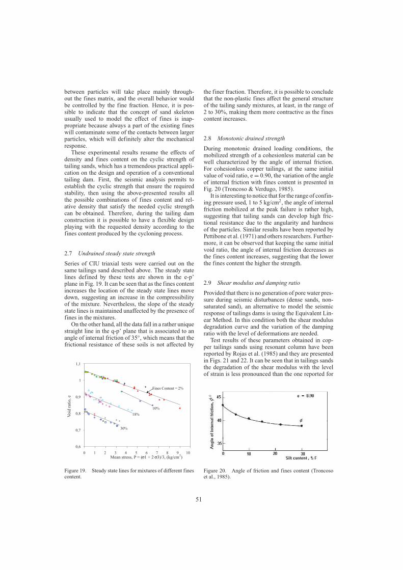
Series of CIU triaxial tests were carried out on thesame tailings sand described above. The steady statelines defined by these tests are shown in the e-p’plane in Fig. 19. It can be seen that as the fines contentincreases the location of the steady state lines movedown, suggesting an increase in the compressibilityof the mixture. Nevertheless, the slope of the steadystate lines is maintained unaffected by the presence offines in the mixtures.
On the other hand, all the data fall in a rather uniquestraight line in the q-p’ plane that is associated to anangle of internal friction of 35◦, which means that thefrictional resistance of these soils is not affected by
0,6
0,7
0,8
0,9
1
1,1
0 1 2 3 4 5 6 7 8 9 10
Vo
id r
atio
, e
Mean stress, P = ( 1 + 2 3)/3, (kg/cm2)
Fines Content = 2%
10%
18%
30%
Figure 19. Steady state lines for mixtures of different finescontent.
the finer fraction. Therefore, it is possible to concludethat the non-plastic fines affect the general structureof the tailing sandy mixtures, at least, in the range of2 to 30%, making them more contractive as the finescontent increases.
2.8 Monotonic drained strength
During monotonic drained loading conditions, themobilized strength of a cohesionless material can bewell characterized by the angle of internal friction.For cohesionless copper tailings, at the same initialvalue of void ratio, e= 0.90, the variation of the angleof internal friction with fines content is presented inFig. 20 (Troncoso & Verdugo, 1985).
It is interesting to notice that for the range of confin-ing pressure used, 1 to 5 kg/cm2, the angle of internalfriction mobilized at the peak failure is rather high,suggesting that tailing sands can develop high fric-tional resistance due to the angularity and hardnessof the particles. Similar results have been reported byPettibone et al. (1971) and others researchers. Further-more, it can be observed that keeping the same initialvoid ratio, the angle of internal friction decreases asthe fines content increases, suggesting that the lowerthe fines content the higher the strength.
2.9 Shear modulus and damping ratio
Provided that there is no generation of pore water pres-sure during seismic disturbances (dense sands, non-saturated sand), an alternative to model the seismicresponse of tailings dams is using the Equivalent Lin-ear Method. In this condition both the shear modulusdegradation curve and the variation of the dampingratio with the level of deformations are needed.
Test results of these parameters obtained in cop-per tailings sands using resonant column have beenreported by Rojas et al. (1985) and they are presentedin Figs. 21 and 22. It can be seen that in tailings sandsthe degradation of the shear modulus with the levelof strain is less pronounced than the one reported for
Figure 20. Angle of friction and fines content (Troncosoet al., 1985).
51

Figure 21. Degradation of shear modulus (Rojas et al.,1985).
Figure 22. Damping ratio (Rojas et al., 1985).
natural sandy soils and the damping ratio achieves lessvalues than natural sandy soils.
On the other hand, the effect of fines content on thedegradation of the shear modulus has been reported byTroncoso & Verdugo (1985) and shown in Fig. 23. It isnoticeable that, for any level of strain, shear modulusdecreases as the fines content increases. Therefore,higher stiffness can be expected in cycloned tailingssands as the fines content decreases.
2.10 Effect of initial fabric
During the genesis of any soil deposit, the sedimen-tation and placement of soil particles is affected bythe gravity force, which generates a preferential parti-cle orientation that makes anisotropic soil structures.Casagrande et al. (1944) named this initial anisotropycaused by the geological process of deposition Inher-ent Anisotropy. Depending upon the environmentalconditions existing during the sedimentation process,the inherent anisotropy may affect significantly thesoil response. This situation is particularly impor-tant in hydraulic fills as the case of tailing dams,where there is not only a preferential orientationof particles, but also a segregation that results ina heterogeneous structure. Hence it is strongly rec-ommended the evaluation of geotechnical propertiesusing samples with the actual structure generated inthe field.
Nevertheless, in saturated tailing sands, the fieldoperation to retrieve ‘‘undisturbed’’ samples for beingtested in the laboratory is complicated and expensive.Furthermore, at the beginning of the projects, whenthe tailing dams are not yet constructed, ‘‘undisturbed’’samples are not available. Consequently, the alterna-tive of testing reconstituted specimens compacted atthe same density expected in the field it is alwaysattractive, but it can not be ignored that the initial fab-ric or structure may have an important effect on thesoil parameters, and therefore efforts has to be done inorder to reproduce the expected actual soil structure.
Figure 23. Shear modulus and fines content, (Troncoso &Verdugo, 1985).
52

Regarding the undrained steady state strengthdeveloped at large strains, there is experimental evi-dence showing that this parameter is independentof the initial inherent anisotropy or initial particlearrangements. However, it has been also shown thatthe steady state strength of non-homogeneous sam-ples is strongly dependent on the initial configurationof particles, which suggests that even pretty largedeformations are not able to erase the initial hetero-geneity (Verdugo, 1992; Verdugo et al., 1995). Hence,it is proposed to divide the initial arrangement of soilparticle in two groups as indicated in Fig. 24.
Firstly, it is possible to identify those homogeneousinitial arrangements of soil particles that can be com-pletely broken down at large deformation, and there-fore can mobilize a unique steady state line. In thesecond group are those particle configurations of het-erogeneous distribution of grains that can not be fullyerased by large deformations, independently of howlarge the strains are. Tailing sand deposits are in thissecond group.
Triaxial tests data obtained from both reconstitutedand ‘‘undisturbed’’ samples of tailing sands have beenreported by Castro et al. (1989), and shown in Fig. 25.It is readily apparent that there is a significant differ-ence between the undrained strength of ‘‘undisturbed’’and reconstituted samples.
These experimental results confirm that an initialheterogeneous structure is not erased at large defor-mation and it develops a different undrained steady
Figure 24. Proposed division of initial arrangement of soilparticle.
Figure 25. Undrained steady state strength from reconsti-tuted and ‘‘undisturbed’’ samples (Castro et al.,1989).
Figure 26. Aging effect on the cyclic strength of tailingsands (Troncoso et al., 1988).
state strength respect to the one reached by the homo-geneous soil mass. Then, for the geotechnical charac-terization of tailing deposits the use of ‘‘undisturbed’’samples is strongly recommended.
2.11 Liquefaction and aging
It has been generally recognized that the liquefactionresistance (cyclic mobility) tends to increase with theage of the deposit, what can be associated to the devel-opment of light cementation or some welding at pointsof grain contact. To study the effect of the time of depo-sition in the cyclic strength of tailing sands, series ofcyclic triaxial tests have been performed on ‘‘undis-turbed’’ samples retrieved from an old tailing dam atdifferent depth, which basically means different age ofthe samples. In addition, tests on fresh samples recon-stituted in the laboratory were carried out (Troncosoet al., 1988). The test results are summarized in Fig. 26,indicating that the cyclic stress ratio required to pro-duce a state of softening with 5% double amplitudestrain tends to increase by a factor of 3.5, 2.4 and 2
53

for the samples of 30, 5 and 1 years of sustaineddeposition, respectively.
Therefore, it is strongly recommended to estimatethe effect of aging for stability analysis during theabandon period. This type of study can be done whenthe tailings dam has been in operation for severalyears, so it is possible to retrieve samples at differentdepths, which are associated to different years of depo-sition. Testing this batch of ‘‘undisturbed’’ samples,it is possible to establish the variation of the cyclicstrength with the age of deposition, which allows anestimation of the improvement of the cyclic resistancewith time.
3 LARGE EARTH DAMS
3.1 Rockfill and gravel-fill dams
Because of the intrinsic exceptional geotechnical prop-erties of coarse materials, they are normally used inthe construction of large earth dams. These materi-als are used in Concrete Face Rockfill Dam (CFRD)and Concrete Face Gravel-fill Dam (CFGD). Thesetypes of dams have increased in number throughoutthe world mainly because of the following two reasons:modern CFRD is a high quality dam type from all tech-nical standpoints and the CFRD is often the lowest-costdam type when the material is readily available at site(Sherard & Cooke,1987).
However, coarse materials as rockfill, cobbles andgravel always present difficulties in the evaluation oftheir properties, commonly due to the lack of suf-ficiently large equipment to test large size particles.Hence in rockfill and gravel-fill dam projects, theavailable information related to mechanical proper-ties of the coarse material of the fill is quite limited.Additionally, an important aspect to bear in mind isassociated with the post construction deformations,which might affect the concrete face.
Therefore, evaluation of mechanical properties andlong term deformations are two important issues thathave to be faced on the design of a rockfill and gravel-fill dams. These topics are addressed in the followingsections.
3.2 Evaluation of mechanical propertiesof coarse soils
Different methods to evaluate mechanical propertiesof coarse soils have been proposed, which involvetesting of ‘‘equivalent’’ soil samples, free of over-sized particles. The matrix model method, the parallelgradation method and the scalping and replacementmethod are the most commonly used methods. In thematrix model, the original coarse soil is divided intwo parts: oversized particles and matrix material.The definition of oversize is arbitrary, and it is related
to the maximum particle size that can be tested in theavailable equipment. It is assumed in this method thatthe oversized particles are in a ‘‘floating’’ state, mean-ing that these particles have little or no contact betweenthem. The matrix material to be tested is compacted toa density that has to be estimated, correspondingto the actual density of the soil matrix in the field(Siddiqi et al., 1987; 1991; Fragaszy et al., 1990; 1992).Therefore, the use if this procedure is limited by thevalidity of the assumption that the oversized particlesare ‘‘floating’’ and the accuracy of the procedure toestimate the actual density of the soil matrix in thefield.
In the scalping-replacement method, all those par-ticles that are considered oversized with respect to theavailable testing equipment are scalped and replacedwith an equal weight of a smaller particle range(Donaghe & Torrey, 1979). This procedure changesdrastically the original soil gradation and, althoughsome experimental data have shown promising results,there is no real evidence to support the equivalencebetween the original soil and the artificially createdbatch of soil scalped and replaced.
In the parallel gradation method, the oversized par-ticles are scalped and a new batch of soil is preparedusing the original material, which has a grain size dis-tribution curve parallel (in the common semi log scale)to that of the original sample (Lowe, 1964; Marachiet al., 1972; Verdugo et al., 2003; Varadajan et al.,2003). The main advantage of this procedure is thatthe soil gradation is maintained. However, depend-ing upon the particular characteristics of each soil, themineralogy and hardness of grains, particle shape, andparticle roughness, may be different and function ofthe particle size (Al-Hussaini, 1983; Cho et al., 2005;Lee et al., 1967; Santamarina et al., 2003 & 2004).In granular soils where these factors are similar forall particle sizes, the parallel gradation method can beseen as an attractive alternative.
Verdugo & De La Hoz (2006) reported test resultsof gravelly soils using the parallel gradation method.The grain size distribution curves and the maximumand minimum densities of one of the material testedare presented in Fig. 27. It is interesting to observethat the maximum and minimum densities are rathersimilar, regardless of the mean grain size, D50. All testswere performed on samples compacted to an initialrelative density of 70% and in a range of confiningpressure between 20 and 600 kPa.
The stress-strain curves and the volumetric strainsof these batches are presented in Fig. 28.
It can be observed that both peak strength and stiff-ness are similar for the different batches.
The stress-strain curves present an initial linearportion that can be represented by the deformationmodulus, E50 (stiffness associated with a stress levelequal to half of the peak strength), which results arepresented in Fig. 29. It is observed that the parallel
54

gradations are able to capture the essential mechanicalresponse of the soils, showing the same expressionfor E50:
E50 = 175(σ3)0.79 (MPa) (1)
0
10
20
30
40
50
60
70
80
90
100
0.01 0.10 1.00 10.00 100.00
Grain size [mm]
Per
cen
t fi
ner
by
wei
gh
t
D50 = 0.71 mm
1.85 mm
3.93 mm
M-2
1.2
1.4
1.6
1.8
2.0
2.2
2.4
0.01 0.10 1.00 10.00 100.00
Mean grain size, D50 [mm]
Dry
Den
sity
[g
r/cm
3] M-2
Maximum densit y
Minimum density
Figure 27. Grain size distribution curves and maximum andminimum densities of samples M-2.
0.0
0.2
0.4
0.6
0.8
1.0
1.2
1.4
1.6
0 2 4 6 8 10 12 14 16 18 20
Axial strain , εa [%]
Dev
iato
ric
stre
ss,
∆σ [
MP
a]
σ0' = 50 kPa
σ0' = 100 kPa
σ0' = 300 kPa
M-2
-1.0
0.0
1.0
2.0
3.0
4.0
5.0
6.0
0 2 4 6 8 10 12 14 16 18 20Axial strain , εa [%]
Volu
met
ric
stra
in, [%
]
D50 = 3.93 mm
D50 = 1.85 mm
D50 = 0.71 mm
M-2
σ0' = 50 kPa
σ0' = 100 kPa
σ0' = 300
Figure 28. Stress-strain curves and volumetric strainsobtained in samples M-2.
E = 175 σ30.79
E = 239 σ30.46
1
10
100
1000
0.11.00.0
Confining pressure, σ3 [MPa]
Mo
du
lus
of
def
orm
atio
n,
E50 [
MP
a]
M-2
M-1
Figure 29. Deformation Modulus, E50 for samples M-2.
3.3 Post-construction deformations
A study of the behavior of the Chilean largest earthdams conducted for the Ministry of Public Workpermitted the analysis of the variation of the staticdeformation modulus of rockfill and gravel-fill dams.In this study, long term post-construction settlementsmonitored on three Chilean earth dams were used toestimate the time variation of the deformation mod-ulus these coarse materials. Basic information of theanalyzed dams is indicated in Table 2.
The static dam response was modeled using aperfect elasto-plastic stress-strain relationship, imple-mented in the computer code FLAC. The evaluationof the deformation modulus was performed by a tryand error process until the calculated and observeddam settlements matched.
The main body of Cogoti dam was finished in 1938and the vertical deformations have been monitoredsince that time. The dam was finally completed in1940.
This dam was constructed with blasted rock with-out compaction. In its first 15 meters, rockfill witha maximum size of 1.5 meters were just dumped inthe dam site by gravity. In the following raises, rock-fill with a maximum size of 1.3 meters was placedby mechanical means and it was slightly compactedby the construction procedure associated to the traffic
Table 2. Monitored chilean dams.
Dam Cogoti Conchi Santa Juana
Completion year 1940 1975 1995Foundation type Rock Rock Rock fluvialDam type CFRD CFRD CFGDHeight (m) 82.7 66.0 113.4Crest length (m) 160 200 390Upstream 1.45:1 1.5:1 1.5:1Slope (H:V)Downstream 1.5:1 1.5:1 1.6:1Slope (H:V)
55
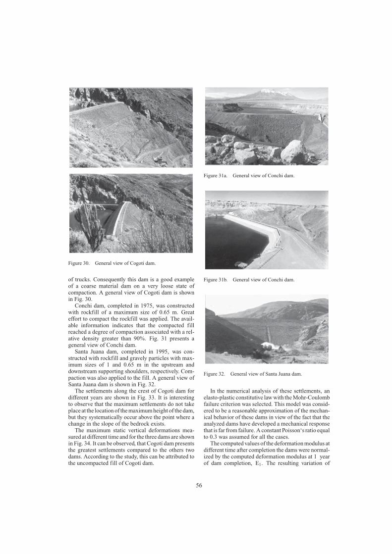
Figure 30. General view of Cogoti dam.
of trucks. Consequently this dam is a good exampleof a coarse material dam on a very loose state ofcompaction. A general view of Cogoti dam is shownin Fig. 30.
Conchi dam, completed in 1975, was constructedwith rockfill of a maximum size of 0.65 m. Greateffort to compact the rockfill was applied. The avail-able information indicates that the compacted fillreached a degree of compaction associated with a rel-ative density greater than 90%. Fig. 31 presents ageneral view of Conchi dam.
Santa Juana dam, completed in 1995, was con-structed with rockfill and gravely particles with max-imum sizes of 1 and 0.65 m in the upstream anddownstream supporting shoulders, respectively. Com-paction was also applied to the fill. A general view ofSanta Juana dam is shown in Fig. 32.
The settlements along the crest of Cogoti dam fordifferent years are shown in Fig. 33. It is interestingto observe that the maximum settlements do not takeplace at the location of the maximum height of the dam,but they systematically occur above the point where achange in the slope of the bedrock exists.
The maximum static vertical deformations mea-sured at different time and for the three dams are shownin Fig. 34. It can be observed, that Cogotí dam presentsthe greatest settlements compared to the others twodams. According to the study, this can be attributed tothe uncompacted fill of Cogotí dam.
Figure 31a. General view of Conchi dam.
Figure 31b. General view of Conchi dam.
Figure 32. General view of Santa Juana dam.
In the numerical analysis of these settlements, anelasto-plastic constitutive law with the Mohr-Coulombfailure criterion was selected. This model was consid-ered to be a reasonable approximation of the mechan-ical behavior of these dams in view of the fact that theanalyzed dams have developed a mechanical responsethat is far from failure. A constant Poisson‘s ratio equalto 0.3 was assumed for all the cases.
The computed values of the deformation modulus atdifferent time after completion the dams were normal-ized by the computed deformation modulus at 1 yearof dam completion, E1. The resulting variation of
56

RockfillRock
1997
1943
Shape of settlement
Figure 33. Vertical settlements along the crest of CogotiDam.
0
10
20
30
40
50
60
70
0 10 20 30 40 50 60 70
Time (years after end of construction)
Set
tlem
ent
(cm
)
Cogoti
Conchi
Santa Juana
Figure 34. Development of the static maximum verticaldeformation.
0.01
0.1
1
10
010111.0 0Time (years)
Cogotí Conchi Santa Juana
E/E
1
35.0
1
1
−
=
T
TEE
Figure 35. Normalized deformation modulus as a functionof time.
the normalized deformation modulus (E/E1) with thenumber of years after completion is shown in Fig. 35.These results indicated that the time effect on the staticdeformation modulus can be expressed as follows:
E = E1(t/t1)−0.35 (2)
Where, t represents time in years after completion andt1 is 1 year after the end of construction. This defor-mation modulus is associated to the total accumulatedsettlements. Therefore, the use of this expression isrelated to the long term settlement evaluation.
4 SUMMARY
The performance-based seismic design is stronglyencouraged by structural engineers that have observedheavy financial losses in recent earthquakes. Struc-tures designed according to current codes performedwell in terms of life safety, but financial losses havebeen surprisingly high. This comes from the factthat the main investments in building constructionare made in the non-structure components and con-tents. Therefore, it is evident that the fundamentalissue of building code provisions to guaranty struc-tures integrity, in terms of no collapse against strongground motion, is definitely insufficient to be con-sidered a successful seismic behavior to the society.In this context the performance-based seismic designwould help to reduce the financial losses associatedwith the non-structure components and contents.
Formally, the use of PBSD is less common ingeotechnical engineering. However, the earthquakegeotechnical community is quite familiar in predictingpermanent displacements of earth structures, whichbasically mean a criterion of performance as opposedto the classical concept of limit equilibrium.
One important issue of PBSD is associated with theintention of involving stakeholders (owners, insurersand regulators) in the decisions concerning the chooseof target performances of an earth structure during andafter seismic events, sharing in this way the decision-making process. In spite of the benefits, it is importantto take into account that the results of combining bothcomplex technical solutions and investment decisionare at least risky.
The second important issue of PBSD is related tothe premise that seismic performance levels can bepredicted analytically, permitting that the cost associ-ated with each level can be rationally evaluated. Froma scientific point of view, there is a reasonable knowl-edge of soil and rock mechanics behavior that hasbeen incorporated into numerical models. However, inengineering practice the real situation is less promis-ing, especially when three dimensional analysis isneeded. Additionally, in the case of dam engineering,practitioners have to face the geotechnical character-ization of rockfill materials, but, normally there is alack of available testing apparatuses for these coarsesoils, which means that in the design, geotechnicalproperties have to be estimated.
In this context, the actual capability of predictingthe seismic performance is quite limited. Conse-quently, it is important to recognize that the realapplication of the PBSD in professional practice isyears away, but it is also important to admit that thisdesign criterion is attractive and efforts have to bedone in order to make it closer to practitioners.
In the PBSD of tailings dams, the liquefactionresistance of the tailings sands play an importantrole, and this resistance is affected by density and
57

the fines content. Therefore, theses effects have to beunderstood. On the hand, the PBSD of concrete facerockfill dams needs the mechanical properties ofthe coarse fill used in these dams. However, suf-ficiently large machines to test these materials arenot usually available, so alternative procedures toobtain the required properties are needed. As can beexpected, material properties are an important issue inthe application of the PBSD and their evaluation andunderstanding is strongly needed.
In the design of tailings dams there are two impor-tant issues that control the liquefaction strength ofthe tailings; density and fines contents. Accordingly,results of a comprehensive study carried out on differ-ent mixtures of sand and fines compacted at differentdensities have been presented.
The maximum density obtained by the ModifiedProctor test is only slightly lower than the maximumdensity achieved by vibration, even for a 50% of fines.Hence, it is possible to indicate that the concept ofrelative density holds valid for this tailings sand evenwith 50% fines or more.
The experimental results show that the cyclicstrength decreases as the fines content increases. Mix-tures with 2 and 10% of fines content present a sharpincrease in cyclic strength from a relative densityaround 50%, while mixtures with 18 and 28% offines content present only a gradual increase of cyclicstrength with relative density.
A rather unique steady state line in the q-p′ planewas obtained for all the mixtures, indicating a constantresidual angle of internal friction of 35◦, regardless thefines content.
Fines content affect the position of the steady statelines in the e-p’ plane. The higher the fines content thelower the position of the steady state line. However,the fines do not affect the slope of the steady statelines.
The amount of non-plastic fines used in this studyaffect the soil structure making it more contractive,and therefore, more sensitive to liquefaction.
From the seismic analysis, the required cyclicstrength can be established and from the presentedresults, the possible combinations of fines contentand relative density that satisfy the required cyclicstrength can be obtained. Therefore, during the tail-ing dam construction it is possible to have a flexibledesign playing with the requested density according tothe fines content produced by the cycloning process.
In the case of large earth dam, these days themost common adopted design corresponds to Con-crete Face Rockfill Dam and Concrete Face Gravel-fill Dam. These types of dams have increased innumber throughout the world mainly because of thegood behavior from all technical standpoints and alsodue to the lower cost. Coarse materials as rockfill,cobbles and gravel always present difficulties in theevaluation of their properties, commonly due to the
lack of available equipment to test large particles.An alternative procedure to evaluate the mechanicalproperties is the parallel gradation method. The over-sized particles are scalped and a new batch of soil isprepared using the original material, which has a grainsize distribution curve parallel (in the common semilog scale) to that of the original sample. The mainadvantage of this procedure is that the soil gradationis maintained.
Experimental results indicate that the parallel gra-dation method provides a quite reasonable procedureto evaluate the geomechanical response of coarse gran-ular materials.
Another issue of Concrete Face Rockfill and Gravel-fill dams is associated with the long term deformationwhich might affect the concrete face. Using a simpleelasto-plastic stress-strain relationship, the measure-ments of three Chilean dams were reproduced and thedeformation modulus computed. The relationship thatreproduced the calculated values of the deformationmodulus can be expressed in the form: E = E1 (t/t1)
b,where E1 (deformation modulus associated to thesettlement of the dam at 1 year after construction)depends upon the dam material, and the parameter bhas shown to be a constant value for rockfill dams;b = −0.35.
ACKNOWLEDGMENTS
The author wants to acknowledge the very useful com-ments done by Dr. Claudia Medina and Dr. JavierUbilla. Also, thanks are due to Dirección de ObrasHidráulicas of the Chilean Ministry of Public Workand IDIEM (Institute for research and testing of mate-rials) of the Faculty of Engineering, University ofChile.
REFERENCES
Al-Hussaini, M. 1983: Effect of particle size and strain condi-tions on the strength of crushed basalt. Canadian Geotech-nical Journal, 20(4): 706–717.
Agüero, G. 1929. Formation of Tailings Deposits in ElTeniente Mine. Anales del Inst. de Ingenieros de Chile.pp. 164–187.
Astrella, M. and Whittaker, A. 2004. Changing the paradigmfor performance based design. Proc. Intern. Workshop onPerformance-Based Seismic Design Concept and Imple-mentation. Slovenia.
Casagrande, A. 1975. Liquefaction and Cyclic Deformationof Sands—A Critical Review. V Panamerican Confer-ence on Soil Mech. & Foundation Eng. Buenos Aires,Argentina.
Casagrande, A. and Carrillo, N. 1944. Shear Failure ofAnisotropic Materials. Proc. Boston Soc. of Civil Eng.Vol. 31, pp. 74–87.
Castro, G. 1969. Liquefaction of Sands. Doctoral Thesis,Harvard University, Cambridge, Mass. USA.
58

Castro, G. and Troncoso, J. 1989. Effects of ChileanEarthquake on three tailing dams. Int. Sem. on DynamicBehavior of Clays, Sands & Gravel. Kitakyushu, Japan.
Conlin, B. 1987. A Review of the Performance of MineTailings Impoundments Under Earthquake Loading Con-ditions. Proceedings Vancouver Geotechnical SocietySeminar on Earthquake. Geot. Canada.
Cubrinovski, M. and Ishihara, K. 2002. Maximum and min-imum void ratio characteristics of sands. Soils and Foun-dations, Vol. 42, No. 6, pp. 65–78.
Cho, G., Dodds, J. and Santamarina, J. (2005): ‘‘ParticleShape effects on parking density, stiffness and strength:Natural and Crushed sands,’’ Internal report. GeorgiaInstitute of Technology.
Dobry, R. and Alvarez, L. 1967. Seismic Failures of ChileanTailings Dams. Journal of Soil Mechanics and FoundationDivision, ASCE, Vol. 93, SM6, pp. 237–260.
Donaghe, R. and Torrey, V. 1979. Scalping and replace-ment effects on strength parameters of earth-rock mix-tures. Proc. Conf. on Design Parameters in GeotechnicalEngineering, London, Vol. 2, pp. 29–34.
Finn, W. 1980. Seismic Response of Tailings Dams. Pro-ceeding Seminar on Design and Construction of TailingsDams. Colorado School of Mines. USA.
Finn, W. 1996. Seismic Design and Evaluation of TailingsDams: State of the Art. Int. Symposium on Seismic andEnvironmental Aspects of Dam Design: Earth, Concreteand Tailing Dams. Chile.
Fragaszy, R., Su, W. and Siddiqi, F. 1990 Effects of oversizeparticles on the density of clean granular soils. Geotech-nical Testing Journal, 13(2): 106–114.
Fragaszy, R., Su, W., Siddiqi, F. and Ho, C. (1992): ‘‘Model-ing strength sandy gravel,’’ Journal of Geotechnical Engi-neering, 118(6): 920–935.
Garga, V. and McKay, L. 1984. Cyclic Triaxial Strengthof Mine Tailings. Journal of Geotechnical Engineering,ASCE, Vol. 110, No. 8, pp. 1091–1105.
Hazen, A. 1920. Hydraulic-Fill Dams. ASCE Transactions,Vol. 83, pp. 1713–1745.
Ishihara, K. 1984. Post-Earthquake Failure of a Tailings DamDue to Liquefaction of the Pond Deposit. Int. Conferenceon Case Histories in Geotechnical Engineering. St. Louis.USA.
Ishihara, K. 1985. Stability of Natural Deposits During Earth-quakes. XI International Conference on Soil Mechanicsand Foundation Engineering. Vol. 2, pp. 321–376.
Ishihara, K. 1993. Liquefaction and Flow Failure Dur-ing Earthquakes. 33rd Rankine Lecture. Geotechnique,Vol. 43, No. 3, pp. 351–415.
Ishihara, K., Troncoso, J. and Kawase, Y. 1980. CyclicStrength Characteristics of Tailings Materials. Soils andFoundations, Vol. 20, No. 4, pp. 128–142.
Lee, K. and Seed, H. 1967. Drained strength characteristicsof sands. Journal of the Soil Mechanics and FoundationsDivision, 93(6): 117–141.
Lowe, J. 1964. Shear Strength of coarse embankment dammaterial. Procedings, 8th Congress on Large Dams,pp. 745–761.
Makdisi, F. and Seed, H.B. 1977. A simplified procedure forestimating earthquake-induced deformations in dams andembankments, EERC Report No. 77/19.
Marachi, D., Chan, C. and Seed, H. 1972. Evaluation of prop-erties of rockfill materials. Journal of the Soil Mechanicsand Foundations Division, 98(1): 95–114.
Miranda, E. and Taghavi, S. 2003. Response assessment ofnonstructural building elements. PEER Report 2002/03,Pacific Earthquake Engineering Research Center, Uni-versity of California, Berkeley, USA.
Newmark, N.M. 1965. Effects of earthquakes on dams andembankments, Geotechnique, Vol. 5, No. 2.
Ni, Q., Tan, T,. Dasari, T. and Hight, D. 2004. Contribu-tion of fines to the compressive strength of mixed soils.Géotechnique 54, No. 9.
Pettibone, H. and Kealy, C. 1971. Engineering Properties ofMine Tailings. Journal of Soil Mechanics and Founda-tions Division, ASCE, Vol. 97, SM9, pp. 1207–1225.
Polito, C. and Martin, J. 2001. Effects of nonplastic fines onthe liquefaction resistance of sands. Journal of Geotechni-cal and Geoenvironmental Engineering. Vol. 127, No. 5.
Poulos, S. 1981. The Steady State of Deformation. J. of Geot.Eng. Division, ASCE, Vol. 107, No. GT5, pp. 553–562.
Poulos, S., Castro, G. and France, J. 1985. Liquefaction Eval-uation Procedure. J. of Geot. Eng., ASCE. Vol. 111, No. 6.
Poulos, S., Robinsky, E. and Keller, T. 1985. LiquefactionResistance of Thickened Tailings. J. of Geotechnical Engi-neering, ASCE. Vol. 111, No. 12, pp. 1380–1394.
Robinsky, E. 2000: Sustainable Development in Disposalof Tailings. Proceedings Tailings and Mine Waste ’00,Colorado State University. USA.
Rojas-González, L., Ben-Khalal, H. and Lewis, K. 1985.Dynamic Properties and Behavior of Copper Tailings. XIInt. Conf. on Soil Mechanics and Foundation Eng. Vol. 3,pp. 1289–1292.
Salvas, R. 1989. Beneficial Characteristics of Sloped TailingsDeposits. International Symposium on Tailings and Efflu-ent Management, Metallurgical Society of the CanadianInstitute of Mines and Metallurgy. Vol. 14. Pergamon Press.
Santamarina, J. and Cho, G. 2004. Soil Behaviour: The roleof particle shape. Proceedings Skempton Conference.London. http://www.ce.gatech.edu/∼carlos/laboratory/tool/Particleshape/Particleshape.htm
Santamarina, J. and Díaz-Rodríguez, J. 2003. Friction inSoils: Micro and Macroscale Observations. Pan-AmericanConference, Boston, 2003.
Seed, H.B. 1966. A method for earthquake-resistant designof earth dams, Journal of the Soil Mechanics and Foun-dations Division, ASCE, Vol. 92, No. SM1.
Sherard, J. and Cooke, B. 1987. Concrete-face rockfill dam:I. Assessment. Journal of Geotechnical Engineering,Vol. 113, No. 10.
Siddiqi, F. and Fragaszy, R. 1991. Strength evaluation ofcoarse grain dam material. IX Pan-American Conference,Viña del Mar, Chile, pp. 1293–1302.
Siddiqi, F., Seed, R., Chan, C., Seed, H. and Pyke, R. 1987.Strength evaluation of coarse-grained soils. EarthquakeEngineering Research Center, University of California,Berkeley, California. Report N◦ UCB/EERC-87/22.
Tatsuoka, F., Muramatsu, M. and Sasaki, T. 1982. Cyclicundrained stress-strain behaviour of dense sands by tor-sional simple shear test. Soils and Foundations, Vol. 22.No. 2, pp. 55–70.
Troncoso, J. and Verdugo, R. 1985. Silt Content and DynamicBehavior of Tailings Sands. XI Int. Conf. on Soil Mechan-ics and Foundation Engineering. Vol. 3. pp. 1311–1314.
Troncoso, J., Ishihara, K. and Verdugo, R. 1988. AgingEffects on Cyclic Shear Strength of Tailings Materials.IX World Conference on Earthquake Engineering, Vol. 3,pp. 121–126. Tokyo, Japan.
59

Valenzuela, L., and Barrera, S. 1995. Large Tailings Dams:Current Practice in Chile. X Panamerican Conf. on SoilMech. and Found. Eng. Mexico. Vol. 3, pp. 1556–1569.
Varadajan, A., Sharma, K., Venkatachalam, K. and Gupta, K.2003. Testing and Modeling two rockfill materials. Jour-nal of Geotechnical and Geoenvironmental Engineering,129(3): 206–218.
Verdugo, R. 1992. Characterization of Sandy Soil BehaviorUnder Large Deformations. Doctoral Thesis, Universityof Tokyo.
Verdugo, R. 1997. Tailings Compaction. IV Chilean Congresson Geotechnical Engineering. Vol. 1, pp. 29–41.
Verdugo, R. and Ishihara, K. 1996. The Steady State of SandySoils. Soils and Foundations. Vol. 36, No. 2, pp. 81–91.
Verdugo, R. and Bard, E. 1996. Maximum and MinimumDensities in Cohesionless Soils. X Panamerican Con-ference on Soil Mechanics and Foundation Engineering,Guadalajara, Mexico. Vol. 1, pp. 582–592.
Verdugo, R., Castillo, P. and Briceño, L. 1995. Initial SoilStructure and Steady State. I International Conf. on Earth-quake Geotechnical Eng. Japan. Vol. 1, pp. 209–214.
Verdugo, R., Gesche, R. and De La Hoz, K. 2003. Metodología
de evaluación de parámetros de resistencia al corte de sue-los granulares gruesos. 12th Pan American Conference onSoil Mechanics & Geotechnical Engineering, Cambridge,MA, pp. 691–696.
Verdugo, R. and De La Hoz, K. 2006. Strength and stiff-ness of coarse granular soils. Soil Stress-Strain Behav-ior: Measurement, Modeling and Analysis. GeotechnicalSymposium in Rome, March 16–17, 2006. Springer.
Verdugo, R. and Viertel, P. 2004. Effect of density and finescontent on the cyclic strength of copper tailings. V Con-greso Chileno de Geotecnia.
60