seismic analysis of multi-storied building with shear walls using
TRANSCRIPT

International Journal of Science and Research (IJSR) ISSN (Online): 2319-7064
Index Copernicus Value (2013): 6.14 | Impact Factor (2014): 5.611
Volume 4 Issue 11, November 2015 www.ijsr.net
Licensed Under Creative Commons Attribution CC BY
Seismic Analysis of Multi-Storied Building with Shear Walls Using ETABS-2013
N. Janardhana Reddy1, D. Gose Peera2, T. Anil Kumar Reddy3
1, 2, 3Bheema institute of Technology, Alur Road, Adoni 518301, Kurnoll dist
Abstract: Shear walls are structural members used to elongate the strength of R.C.C. structures. These shear walls will be construct in
each level of the structure, to form an effective box structure. Equal length shear walls are placed symmetrically on opposite sides of
outer walls of the building. Shear walls are added to the building interior to provide more strength and stiffness to the building when
the exterior walls cannot provide sufficient strength and stiffness. It is necessary to provide these shear walls when the tolerable span-
width ratio for the floor or roof diaphragm is exceeded. The present work deals with a study on the improvement location of shear walls
in symmetrical high rise building. Position of shear walls in symmetrical buildings has due considerations. In symmetrical buildings,
the center of gravity and center of rigidity coincide, so that the shear walls are placed symmetrically over the outer edges or inner edges
(like box shape). So, it is very necessary to find the efficient and ideal location of shear walls in symmetrical buildings to minimize the
torsion effect. In this work a high rise building with different places of shear walls is considered for analysis. The multi storey building
with 14 storeys is analyzed for its displacement, strength and stability using ETABS-2013 software. For the analysis of the building for
seismic loading with two different Zones (Zone-II & Zone-V) is considered with a soil I & soil III types. The analysis of the building is
done by using equivalent static method and dynamic method. The results from the analysis obtained from both the methods are
presented in tabular form and the results are compared using graphical form Keywords: ETABS-2013, SHEAR WALL, IS 456-2000, IS1893-2002 1. Introduction Adequate stiffness is to be ensured in high rise buildings for resistance to lateral loads induced by wind or seismic events. Reinforced concrete shear walls are designed for buildings located in seismic areas, because of their high bearing capacity, high ductility and rigidity. In high rise buildings, beam and column dimensions work out large and reinforcement at the beam-column joins are quite heavy, so that, there is a lot of clogging at these joints and it is difficult to place and vibrate concrete at these places which does not contribute to the safety of buildings. These practical difficulties call for introduction of shear walls in High rise buildings. 1.1 Structural forms Lateral loads can develop high stresses, produce sway movement or cause vibration. Therefore, it is very important to have sufficient strength for the structure against vertical loads. Earthquake and wind forces are the only major lateral forces that affect the buildings. The function of lateral load resisting systems or structure form is to absorb the energy induced by these lateral forces by moving or deforming without collapse. The determination of structural form of a tall building or high rise building would perfectly involve only the arrangement of the major structural elements to resist most efficiently the various combinations of lateral loads and gravity loads. The internal planning 1. The material and the method of construction 2. The nature and magnitude of the horizontal loading 3. The external architectural treatment 4. The height and proportions of the building and 5. The planned location and routing of the service systems
The taller and more the slender a structure, the more important the structural factors become and the more necessary it is to choose an appropriate structural form or the lateral loading system for the building. In high rise buildings which are designed for a similar purpose and of the same height and material, the efficiency of the structures can be compared by their weight per unit floor area. 1.2 Factors affecting earthquake design of structure 1) Natural frequency of the building 2) Damping factor of the structure 3) Type of foundation of the structure 4) Importance of the building 5) Ductility of the structure Quite a few methods are available for the earthquake analysis of buildings; two of them are presented here: a. Equivalent Static Lateral Force Method (pseudo static method). b. Dynamic analysis.
(1) Response spectrum method. (2) Time history method.
2. Required Indian Standard Codes IS 456:2000 As per clause 32, design for wall describes, design of horizontal shear in clause 32.4 given details of how shear wall have to be constructed. IS 1893-2002 Criteria of Earth Quake resistant Buildings Part (3) page23, clause4.2 gives the estimation of earth quake loads. IS 13920:1993 it gives the ductile detailing of shear wall as per clause9, where 9.1 gives general requirements,9.2 shear
Paper ID: NOV151322 1030

International Journal of Science and Research (IJSR) ISSN (Online): 2319-7064
Index Copernicus Value (2013): 6.14 | Impact Factor (2014): 5.611
Volume 4 Issue 11, November 2015 www.ijsr.net
Licensed Under Creative Commons Attribution CC BY
strength 9.3 give flexural strength 9.6 give openings in shear walls. Ductile detailing, as per the code IS: 13920:1993 is considered very important as the ductile detailing gives the amount of reinforcement required and the alignment of bars. 3. Shear Wall A shear wall is a wall that is used to resist the shear, produced due to lateral forces. Many codes made the shear wall design for high rise buildings a mandatory. Shear walls are provided when the centre of gravity of building area and loads acted on structure differs by more than 30%. To bring the centre of gravity and centre of rigidity in range of 30%, concrete walls are provided i.e. lateral forces may not increase much. These shear walls start at foundation level and extend throughout the building height. The thickness of the shear wall may vary from 150mm to 400mm. Shear walls are oriented in vertical direction like wide beams which carry earthquake loads downwards to the foundation and they are usually provided along both width and length of the buildings. Shear walls in structures located at high seismic regions require special detailing. The construction of shear walls is simple, because reinforcement detailing of walls is relatively straight forward and easy to implement at the site. Shear walls are effective both in construction cost and effectiveness in minimizing earthquake damage to the structural and non structural elements also. 3.1Shapes or Geometry of Shear Walls Shear walls are rectangle in cross section, i.e. one dimension is much larger than the other. While rectangular cross-section is frequent, L- and U-shaped sections are also used. Thin-walled hollow RC shafts around the elevator core of the structure also act as shear walls, and should be taken advantage of to resist earthquake forces. The Shear Wall sections are classified as six types. (a) Box Section (b) L – Section (c) U - Section (d) W – Section (e) H - Section (f) T – Section
Figure 5.1: Different shapes or geometries of shear walls
3.2 Classification according to behaviour Shear walls can also be classified according to their behaviour also, they are as follows: a) Shear-shear walls in which strength and deflection are
controlled by shear. These types of shear walls are usually constructed in low rise buildings.
b) Ordinary moment shear walls in which deflection and strength are controlled by means of flexure. These are generally used in high rise buildings to resist high winds and cyclones.
c) Ductile moment shear walls are special walls meant for seismic regions and which have good energy dissipation characteristics under reversed cyclic loads.
3.3 Components of Shear Walls Reinforced concrete and reinforced masonry shear walls are seldom-simple walls which resist the lateral forces. Whenever a wall has doors, windows, or other openings, the wall must be considered as an assemblage of relatively flexible components like column segments and wall piers and relatively stiff elements like wall segments. a) Column segments: A column segment is a vertical
member whose height exceeds three times its thickness and whose width is less than two and one-half times its thickness. Its load is usually mainly axial. Although it may contribute little to the lateral force resistance of the shear wall is rigidity must be considered. When a column is built integral with a wall, the portion of the column that project from the face the wall is called a pilaster. Column segments shall be designed according to ACI 318 for concrete.
b) Wall piers: A wall pier is a segment of a wall whose horizontal length is between two and one-half and six times its thickness whose clear height is at least two times its horizontal length.
c) Wall segments: Wall segments are components of shear wall that are longer than wall piers. They are the primary resisting components in the shear wall.
Important features in planning and design of shear walls: For all high rise buildings, the problem of providing adequate stiffness and preventing large displacements, are as important as providing adequate strength. Thus shear wall system has two distinct advantages over a frame system. 4. Lateral Forces The design of multi-storey structures is governed by lateral load resistance requirements in addition with gravity loads. The magnitude of the lateral force on a structure is not only dependent on the acceleration of the ground but also it
Paper ID: NOV151322 1031

International Journal of Science and Research (IJSR) ISSN (Online): 2319-7064
Index Copernicus Value (2013): 6.14 | Impact Factor (2014): 5.611
Volume 4 Issue 11, November 2015 www.ijsr.net
Licensed Under Creative Commons Attribution CC BY
depends on the type of the structure. The term lateral loads describes the effect of seismic and wind forces, even though in the recent past it included any horizontal applied forces, this terminology seeks to differentiate lateral loads from the downward acting gravity loads, even though in reality the seismic and wind forces can act in both vertical and horizontal directions. Modern building codes require that wind be applied perpendicular to roof surfaces nearly upward for shallow roofs and that a percentage of earthquake loading be applied vertically. 5. Methodology 5.1 Design Aspect Earthquakes can occur on both land and sea, at any place on the surface of the earth where there is a major fault. When earthquake occurs on land it affects the man made structure surrounding its origin leading to human lose. When a major earthquake occurs underneath the ocean or sea, it not only affects the structures near it, but also produces large tidal waves known as Tsunami, thus affecting the places far away from its origin. All the structures are designed for the combined effects of gravity loads and seismic loads to verify that sufficient vertical and lateral strength and stiffness are achieved to satisfy the structural concert and acceptable deformation levels prescribed in the governing building code. Because of the innate factor of safety used in the design specifications, most structures tend to be adequately protected against vertical shaking. Vertical acceleration should also be considered in structures with large spans, those in which stability for design, or for overall stability analysis of structures. 1. Serviceability limit state: The structure undergoes little or no structural damage in this case. Important buildings such as hospitals, atomic power stations, places of assembly etc, which affects a community, should be designed for elastic behavior under expected earthquake forces. These types of structures should be serviceable even after the occurrence of earthquake or cyclones. 2. Damage controlled limit state: In this case, if an earthquake or cyclone occurs, there can be some damage to the structure but it can be repaired even after the occurrence of the disaster. Most of the permanent buildings should come under this category, so, the structure should be designed for limited ductility response only. 3. Survival limit state: In this case, the structure is allowed to be damaged in the event of earthquake or cyclone disasters. But, the supports should stand and support the permanent loads coming on to it so that there should be no caving in of the structure and no loss of life. Limited ductile response is cheaper and full ductile response is cheapest. The full ductile detailing is achieved by the theory of plastic hinge formation and also by careful ductile detailing. The current design practice is to construct the structures for the first two limit states as the other is under development stage.
5.2 Design approach in IS 1893 (2002) The title of IS 1893-2002 is “Criteria for earthquake resist design of structures” and part 1 of this code deals with General Provisions and buildings [1]. According to this code we consider the following magnitudes of earthquakes: a) Design basic earthquake (DBE): It is the earthquake which
occurs reasonably at least once during the designed life of the structure.
b) Maximum considered earthquake (MCE): This is the most severe earthquake that can occur in that region as considered by the code. It is divided by factor 2 to get design basic earthquake.
The value of Z, the seismic zone factor given in the code relates the realistic values of effective peak ground acceleration considering MCE and the service life of the structure. The following principles are the basis for the design approach recommended by IS 1893-2002. 1) The structure should have the strength to withstand minor
earthquakes less than DBE without any damage. 2) The structure should able to resist earthquakes equal to
DBE without significant damage though some non structural damage may occur
3) The structure should able to withstand an earthquake equal to MCE without collapse so that there is no loss of life
As, the actual forces will be much larger than the design forces specified by the code, the ductility arising from the inelastic material behavior and detailing along with the reserve strength are relied upon to account for the difference in the actual and the design lateral loads. Conceptual representation of earthquake resistant design philosophy is depicted in the following figure;
Figure 7.1: Schematic diagram depicting earthquake
resistant design philosophy for different levels shaking
5.3 Equivalent Static Method The equivalent static method of finding lateral forces is also known as the static method or the seismic coefficient method. This method is the simplest one and it requires less computational attempt and is based on formulae given in the code of practice. In all the methods of analyzing a multi storey buildings recommended in the code, the structure is treated as discrete system having concentrated masses at floor levels which comprise the weight of columns and walls in any storey should be equally distributed to the floors above
Paper ID: NOV151322 1032

International Journal of Science and Research (IJSR) ISSN (Online): 2319-7064
Index Copernicus Value (2013): 6.14 | Impact Factor (2014): 5.611
Volume 4 Issue 11, November 2015 www.ijsr.net
Licensed Under Creative Commons Attribution CC BY
and below the storey. In addition, the suitable amount of imposed load at this floor is also lumped with it. It is also assumed that the structure flexible and will deflect with respect to the position of foundation; the lumped mass system reduces to the solution of a system of second order differential equations. These equations are formed by distribution of mass and stiffness in a structure, together with its damping characteristics of the ground motion. 5.4 Design Seismic Base Shear The design seismic base shear or total design lateral force (VB) along any principal direction shall be determined by the following expression:
VB = Ah X W Where, Ah = Design horizontal acceleration spectrum value using the fundamental natural period „T‟ in the considered direction of vibration W = seismic weight of the building
The Ah shall be determined by the following expression: Provided that for any building with T less than 0.1s, the value of Ah shall not be taken less than Z/2 whatever be the value of I/R. Where, Z = Zone factor is determined from the following table
Seismic Zone II III IV V Seismic intensity Low Moderate Severe Very severe
Z 0.10 0.16 0.24 0.36 Zone factor given in the above table is for the Maximum Considered Earthquake (MCE) and service life of structure in a zone. The factor 2 in the denominator of Z is used so as to reduce the Maximum Considered Earthquake (MCE) zone factor to the factor for Design Basis Earthquake (DBE). I = I represents the importance factor and it depends upon the functional use of the structures. It is characterized by hazardous consequences of its failure, post earthquake functional needs, historical value or economic importance. 1.5 is considered for the important structures like hospitals, schools, monumental buildings etc. and the rest of the buildings it is taken as 1. R = It is Response reduction factor which depends on the perceived seismic damage performance of the structure, characterized by ductile or brittle deformations of the structure. This ration should not be greater than one. The values for R are given in Table 7 of IS: 1893. The value for R varies between 3 and 5 with respect to ductile reinforcement detailing. Sa/g = Average response acceleration coefficient as per clause 6.4.5 of IS 1893:2002 as given by below figure and it is based on the damping and the natural periods of the structures.
Note: The value of Ah will not be taken less than ½ where ever the value of l/R. 5.5 Time Period The approximate fundamental natural period of vibration Ta in seconds, of a moment resisting frame building without brick infill panels may be estimated by the following empirical formula
For RC frame building
For steel frame building The approximate fundamental natural period of vibration in seconds of all other, buildings including moment resisting frame buildings with brick infill panels may be estimated by the following expression.
Where, H = Height of building in meters (This excludes the basement storey, where basement walls are connected with the ground floor deck or fitted between the columns. But, it includes the basement storey, when they are not connected). D = Base dimensions of the building at the plinth level, in m, along the considered direction of the lateral force. 5.6 Seismic Weight The seismic weight of a structure is the sum of seismic weight of all the floors in the structure. The seismic weight of every floor is the sum of its full dead load and appropriate amount of imposed load, the latter being that element of the imposed loads that may sensibly be expected to be attached to the structure at the time of earthquake movement. It includes the weight of permanent and movable partitions, permanent equipment, a part of the live load, etc. While computing the seismic weight of walls and columns in any storey shall be equally distributed to the floors above and below the storey. 5.7 Distribution of Design Force The computed base shear is now distributed along the height of the building. The shear force, at any level depends on the mass at that level and tends to deform the shape of the structure. Earth quake forces deflect the structure into number of shapes known as the natural mode shapes and the
Paper ID: NOV151322 1033

International Journal of Science and Research (IJSR) ISSN (Online): 2319-7064
Index Copernicus Value (2013): 6.14 | Impact Factor (2014): 5.611
Volume 4 Issue 11, November 2015 www.ijsr.net
Licensed Under Creative Commons Attribution CC BY
number of natural mode shapes depends up on the degree of freedom of the system. Generally a structure has continuous system with infinite degree of freedom. The magnitude of the lateral force at a particular floor depends on the mass of the node, the distribution of stiffness over the height of the structure and the nodal displacement in the given mode. The design base shear (VB) computed by using the above expression shall be distributed along the height of the building as per the following expression:
Where,
= Design lateral force at floor i.
= Seismic weight of floor i.
= Height of floor i measured from base, and n = Number of stores in the building i.e., the number of levels at which the masses are located. The distribution suggested in the code gives parabolic distribution of seismic forces such that seismic shears are higher near top storey for the same base shear. The assumptions involved in the static procedure reflected in the expression are a) fundamental mode of the building makes the most significant contribution to base shear, and b) The total building mass is considered as against the modal mass that would be used in a dynamic procedure. The mass and stiffness are evenly distributed in the building. 5.8 Dynamic Analysis Dynamic analysis shall be carried out to obtain the design seismic force, and its distribution in different levels along the height of the building, and in the various lateral loads resisting element, for the following buildings: Regular buildings: Those greater than 40m in height in zones IV and V, those greater than 90m in height in zone II and III. Irregular buildings: All framed buildings higher than 12m in zones IV and V, and those greater than 40m in height in zones II and III. The analysis of model by dynamic analysis of buildings with unusual configuration should be such that it sufficiently models the types of irregularities present in the building configuration. Buildings with plan irregularities, as defined in Table 4 of IS code: 1893-2002 cannot be modeled for dynamic analysis. Dynamic analysis may be performed either by the TIME HISTORY METHOD or by the RESPONSE SPECTRUM METHOD, 5.9 Time History Method The usage of this method shall be on an appropriate ground motion and shall be performed using accepted principles of
dynamics. In this method, the mathematical model of the building is subjected to accelerations from earthquake records that represent the expected earthquake at the base of the structure. 6. Numerical Modeling and Analysis 6.1 Geometrical Properties
1) Height of typical storey = 3 m 2) Height of ground storey = 3.2 m 3) Length of the building = 35 m 4) Width of the building = 35 m 5) Span in X- direction = 5 m 6) Span in Y-direction = 5 m 7) Height of the building = 43.7 m 8) Number of stores = 14 9) Brick wall thickness = 230 mm 10) Slab Thickness = 120 mm 11) Grade of the concrete = M30 12) Grade of the steel = Fe415 13) Thickness of shear wall = 230 mm 14) Column sizes = 0.7 m X 0.45 m1th story 0.6m X 0.45 m,
2nd to 9th storey 0.45m X 0.3 m 10th to 14th storey XV. Beam sizes = 0.3 m X 0.45 m 1th to 9th storey 0.3 m X 0.3 m 10th to 14th storey 6.2 Loads 1. Live load Live load from 1st floor to 14th floor = 2 kN/m2 Live load on 14th floor = 1.5 kN/m2
2. Dead load Dead load is taken as prescribed by the IS: 875 -1987 (Part-I) [3] Code of Practice Design Loads (other than earthquake) for Buildings and structure. Unit weight of R.C.C. = 25 kN/m3 Unit weight of brick masonry = 19 kN/m3 Floor finish = 1.5 kN/m2 Water proofing =2 kN/m² on terrace roof Wall load = 13.8 kN/m on all floors Expect terrace Roof =6.9 kN/m on terrace roof 3. Seismic Loading In the present work the building is located in Hyderabad which comes under –zone-II and Jammu Kashmir comes under Zone V, using the IS 1893 (Part-I) – 2002(1) the following are the various values for the building considered. a. Zone factor (Z): It is a factor to obtain the design spectrum depending on (lie perceived maximum seismic risk characterized by Maximum considered Earthquake (MCE) in the zone in which the structure is located. The basic zone factors included in this standard are reasonable estimate of effective peak ground acceleration. Zone factor = 0.10 (Zone-II) (from IS 1893 (Part-I)-2002, Table.- 2). Zone factor = 0.36 (Zone-V) (from IS 1893 (Part-I)-2002,
Paper ID: NOV151322 1034
International Journal of Science and Research (IJSR) ISSN (Online): 2319-7064
Index Copernicus Value (2013): 6.14 | Impact Factor (2014): 5.611
Volume 4 Issue 11, November 2015 www.ijsr.net
Licensed Under Creative Commons Attribution CC BY
Table.- 2). b. Response reduction factor I: It is the factor by which the actual base-shear force that would be generated if the structure were to remain elastic during its response to the Design Basis Earthquake (DBE) shaking, shall by reduced to obtain the design lateral force. Response reduction factor = 5.0 (from IS 1893 (Part-1)-2002, Table-7. I c. Importance factor (I): It is a factor used to obtain the design seismic force depending on the functional use of the structure, characterized by hazardous consequences of post-earthquake functional need, historical value, or economic importance. Importance factor (1) = 1 (from IS 1893-2002 (Part-I), Table-6 d. Soil Type Soil site factor (1 for hard soil, 2 for medium soil, and 3 for soft soil) depending on type of soil average response acceleration coefficient Sa/g is calculated corresponding to 5% damping Refer Clause 6.4.5 of IS 1893-2002. In the present work three type of soil are used. Soil type considered is medium soil, factor 2. e. Damping The effect of internal friction, imperfect elasticity of material, slipping, sliding etc in reducing the amplitude of vibration and is expressed as a percentage critical damping. Damping – 5% 6.3 Material Properties Modulus of Elasticity The modulus of elasticity is primarily influenced by the elastic properties of the aggregate and to a lesser extent by the condition of curing and age of the concrete, the mix proportions and the type of cement. The modulus of elasticity is normally related to the compressive strength of concrete. The modulus of elasticity of reinforced concrete members can be assumed as E=5000√fck Eq, (17) [3] from IS 456:2000 Where, E = modulus of elasticity in kN /m2 fck = Characteristic cube compressive strength of concrete in N/mm2 The modulus of elasticity of reinforced concrete members for M30 grade concrete is E= 27386.127 KN /m2. Poisson’s Ratio: Poisson‟s ratio is the ratio between lateral strains to the longitudinal strain. It is generally denoted by the letters for normal concrete the value of Poisson‟s ratio lies in the range of 0.15 to 0.20 when actually determined from strain measurement. For the present work Poisson‟s ratio is assumed as 0.2 for reinforced concrete.
6.4 Load Combinations The following Load Combinations have been considered for the design
The following Load Combinations have been considered for the design
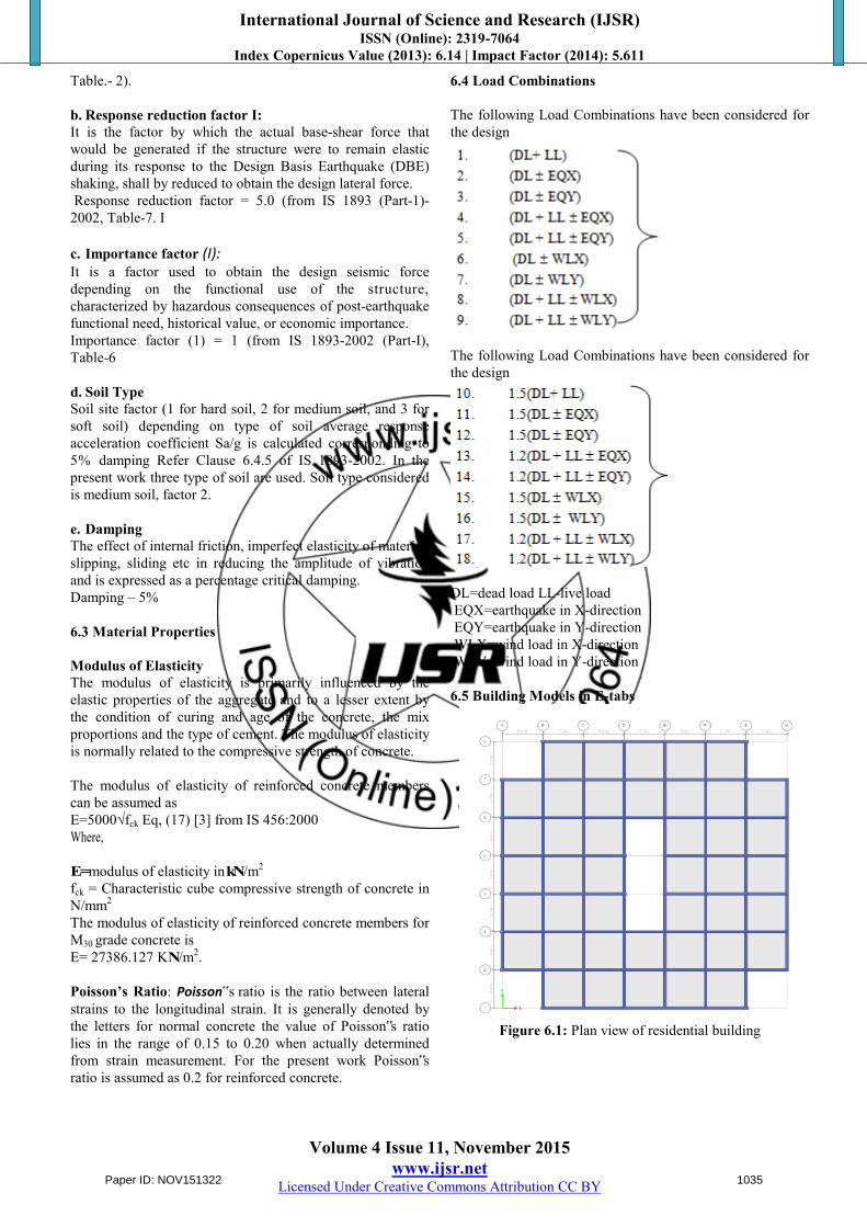
DL=dead load LL-live load EQX=earthquake in X-direction EQY=earthquake in Y-direction WLX=wind load in X-direction WLY=wind load in Y-direction 6.5 Building Models in E-tabs
Figure 6.1: Plan view of residential building
Paper ID: NOV151322 1035

International Journal of Science and Research (IJSR) ISSN (Online): 2319-7064
Index Copernicus Value (2013): 6.14 | Impact Factor (2014): 5.611
Volume 4 Issue 11, November 2015 www.ijsr.net
Licensed Under Creative Commons Attribution CC BY
Figure 6.2: Plan view of high rise building with
SHEARWALL
Figure 6.3: 3D view of high rise building without
SHEARWALL
Figure 6.4: 3D view of high rise building with
SHEARWALL 7. Results & Discussions 7.1 Study on Displacement Sw-shear wall
Table 7.1: Comparison values of max displacement for
Zones in soil-I in static analysis
zones soil-I
without sw with sw zone2 19.085mm 7.49mm zone5 41.17mm 16.124mm
Graph 7.1: Displacements vs zones in soil-I in static analysis
Table 7.2: Comparison values of max displacement for
Zones in soil-III in static analysis
zones soil-III without sw with sw
zone2 31.84mm 10.78mm zone5 68.7435mm 23.22mm
Paper ID: NOV151322 1036
International Journal of Science and Research (IJSR) ISSN (Online): 2319-7064
Index Copernicus Value (2013): 6.14 | Impact Factor (2014): 5.611
Volume 4 Issue 11, November 2015 www.ijsr.net
Licensed Under Creative Commons Attribution CC BY
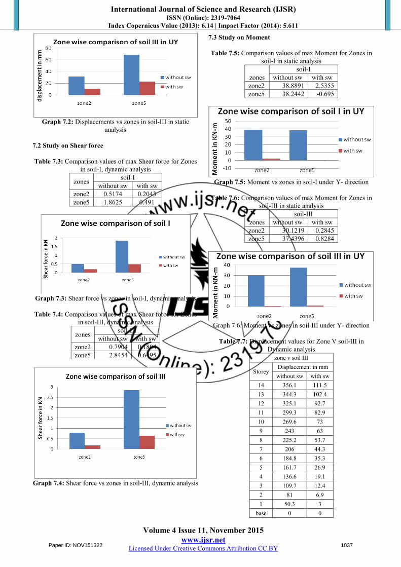
Graph 7.2: Displacements vs zones in soil-III in static
analysis
7.2 Study on Shear force
Table 7.3: Comparison values of max Shear force for Zones in soil-I, dynamic analysis
zones soil-I without sw with sw
zone2 0.5174 0.2043 zone5 1.8625 0.491
Graph 7.3: Shear force vs zones in soil-I, dynamic analysis
Table 7.4: Comparison values of max Shear force for Zones
in soil-III, dynamic analysis
zones soil-III without sw with sw
zone2 0.7904 0.1804 zone5 2.8454 0.6495
Graph 7.4: Shear force vs zones in soil-III, dynamic analysis
7.3 Study on Moment
Table 7.5: Comparison values of max Moment for Zones in soil-I in static analysis
zones soil-I
without sw with sw zone2 38.8891 2.5355 zone5 38.2442 -0.695
Graph 7.5: Moment vs zones in soil-I under Y- direction
Table 7.6: Comparison values of max Moment for Zones in
soil-III in static analysis
zones soil-III
without sw with sw zone2 30.1219 0.2845 zone5 37.4396 0.8284
Graph 7.6: Moment vs zones in soil-III under Y- direction
Table 7.7: Displacement values for Zone V soil-III in
Dynamic analysis zone v soil III
Storey Displacement in mm without sw with sw
14 356.1 111.5 13 344.3 102.4 12 325.1 92.7 11 299.3 82.9 10 269.6 73 9 243 63 8 225.2 53.7 7 206 44.3 6 184.8 35.3 5 161.7 26.9 4 136.6 19.1 3 109.7 12.4 2 81 6.9 1 50.3 3
base 0 0
Paper ID: NOV151322 1037
International Journal of Science and Research (IJSR) ISSN (Online): 2319-7064
Index Copernicus Value (2013): 6.14 | Impact Factor (2014): 5.611
Volume 4 Issue 11, November 2015 www.ijsr.net
Licensed Under Creative Commons Attribution CC BY
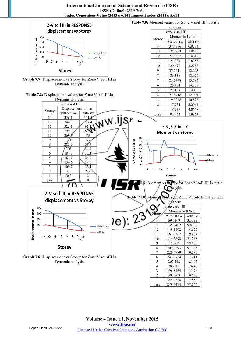
Graph 7.7: Displacement vs Storey for Zone V soil-III in
Dynamic analysis
Table 7.8: Displacement values for Zone V soil-III in Dynamic analysis
zone v soil III
Storey Displacement in mm without sw with sw
14 356.1 111.5 13 344.3 102.4 12 325.1 92.7 11 299.3 82.9 10 269.6 73 9 243 63 8 225.2 53.7 7 206 44.3 6 184.8 35.3 5 161.7 26.9 4 136.6 19.1 3 109.7 12.4 2 81 6.9 1 50.3 3
base 0 0
Graph 7.8: Displacement vs Storey for Zone V soil-III in
Dynamic analysis
Table 7.9: Moment values for Zone V soil-III in static analysis
Graph 7.9: Moment vs Storey for Zone V soil-III in static
analysis
Table 7.10: Moment values for Zone V soil-III in Dynamic analysis
zone v soil III
Storey Moment in KN-m without sw with sw
14 69.5269 3.3399 13 135.3402 9.8739 12 149.1162 14.627 11 162.7367 19.404 10 315.3898 22.268 9 190.02 79.083 8 205.0293 91.105 7 220.4989 102.85 6 242.7754 113.11 5 265.242 121.03 4 286.201 124.48 3 296.8164 121.76 2 308.803 107.78 1 344.2328 119.50
base 279.4494 77.066
zone v soil III
Storey Moment in KN-m
without sw with sw 14 37.4396 0.8284 13 18.7273 1.8486 12 21.7692 2.4619 11 21.083 2.8755 10 20.696 3.2783 9 37.7411 12.223 8 26.136 12.956 7 25.5448 13.793 6 25.464 14.239 5 23.108 14.18 4 21.6418 12.991 3 19.9088 10.828 2 17.934 5.2061 1 18.237 4.0658
base 0.2942 1.9363
Paper ID: NOV151322 1038
International Journal of Science and Research (IJSR) ISSN (Online): 2319-7064
Index Copernicus Value (2013): 6.14 | Impact Factor (2014): 5.611
Volume 4 Issue 11, November 2015 www.ijsr.net
Licensed Under Creative Commons Attribution CC BY
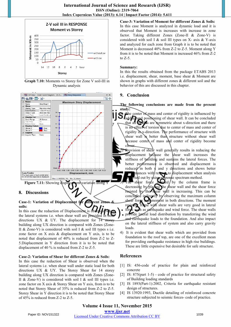
Graph 7.10: Moments vs Storey for Zone V soil-III in
Dynamic analysis
Figure 7.11: Showing displacement variation along Y
8. Discussions Case-1: Variation of Displacement for different zones & soils: In this case the reduction of Displacement is observed when the lateral systems i.e. when shear wall are provided in both directions UX & UY. The displacement for 14 storey building along UX direction is compared with Zones (Zone-II & Zone-V) is considered with soil I & soil III types s i.e. zone factor on X axis & displacement on Y axis, is to be noted that displacement of 40% is reduced from Z-2 to Z-5.Displacement in Y direction from it is to be noted that displacement of 40 % is reduced from Z-2 to Z-5. Case-2: Variation of Shear for different Zones & Soils: In this case the reduction of Shear is observed when the lateral systems i.e. when shear wall under static load for both directions UX & UY. The Storey Shear for 14 storey building along UX direction is compared with Zones (Zone-II & Zone-V) is considered with soil I & soil III types i.e. zone factor on X axis & Storey Shear on Y axis, from is to be noted that Storey Shear of 35% is reduced from Z-2 to Z-5. Storey Shear in Y direction it is to be noted that Storey Shear of 45% is reduced from Z-2 to Z-5.
Case-3: Variation of Moment for different Zones & Soils: In this case Moment is analyzed in dynamic load and it is observed that Moment is increases with increase in zone factor. Taking different Zones (Zone-II & Zone-V) is considered with soil I & soil III types on X- axis & Y-axis and analyzed for each zone from Graph it is to be noted that Moment is decreased 40% from Z-2 to Z-5. Moment along Y from it is to be noted that Moment is increased 46% from Z-2 to Z-5. Summary: In this the results obtained from the package ETABS 2013 i.e. displacement, shear, moment, base shear & Moment are shown in graphs with different zones & different soil and the behavior of this are discussed in this chapter. 9. Conclusion The following conclusions are made from the present study: 1) The center of mass and center of rigidity is influenced by
adding and positioning of shear wall. It can be concluded that all models are symmetric about x-direction and there is no effect of torsion due to center of mass and center of rigidity in x-direction. The performance of structure with shear wall is better than structure without shear wall because center of mass and center of rigidity become closer.
2) Provision of shear wall generally results in reducing the displacement because the shear wall increases the stiffness of building and sustains the lateral forces. The better performance is observed and displacement is reduced in both x and y directions and shows better performances with respect to displacement when analysis is carried out by using response spectrum method.
3) The shear force resisted by the column frame is decreasing by placing the shear wall and the shear force resisted by the shear wall is increasing. This can be concluded indirectly by observing the maximum column shear force and moment in both directions. The moment resisting frame with shear walls are very good in lateral force such as earthquake and wind force. The shear walls provide lateral load distribution by transferring the wind and earthquake loads to the foundation. And also impact on the lateral stiffness of system and also carry gravity loads.
4) It is evident that shear walls which are provided from foundation to the roof top, are one of the excellent mean for providing earthquake resistance in high rise buildings. These are little expensive but desirable for safe structure.
References [1] IS: 456-code of practice for plain and reinforced
concrete [2] IS: 875(part 1-5) - code of practice for structural safety
of Building loading standards [3] IS 1893(Part-1):2002, Criteria for earthquake resistant
design of structures. [4] IS 13920:1993, Ductile detailing of reinforced concrete
structure subjected to seismic forces- code of practice.
Paper ID: NOV151322 1039

International Journal of Science and Research (IJSR) ISSN (Online): 2319-7064
Index Copernicus Value (2013): 6.14 | Impact Factor (2014): 5.611
Volume 4 Issue 11, November 2015 www.ijsr.net
Licensed Under Creative Commons Attribution CC BY
[5] SP: 16-design aids for reinforced concrete [6] Earthquake resistant design by pankaj agarwal. [7] Rosinblueth and Holtz “Analysis of shear walls in tall
buildings” (1960) [8] Clough.R, King I.P and Wilson E.I-“Structural analysis
of multi storied buildings” (1964)
Author Profile
N. Janardhana Reddy received the B. Tech Degree in Civil Engineering from Jawaharlal Nehru Institute of Technology (Ananatapur) in 2009 to 2013 . pursuing M. Tech specialization computer aided structural engineering in Bheema Institute of
Technology Adoni 516501 in Kurnool dist.
Table 3: Histopathological Findings Age Histopathological Findings
Fatty changes Cirrhosis Congestion Hepatitis Malignancy Others Normal M F T M F T M F T M F T M F T M F T M F T
0-30 13 8 21 2 0 2 0 0 0 1 2 3 0 1 1 7 8 15 39 16 55 31-40 16 3 19 4 0 4 4 3 7 9 0 9 0 0 0 7 0 7 1 3 4 41-50 21 5 26 5 0 5 29 2 31 1 0 1 0 0 0 4 3 7 0 0 0 51-60 22 7 29 2 0 2 4 1 5 9 1 10 0 0 0 11 0 11 2 0 2 61-70 12 2 14 6 0 6 15 3 18 8 2 10 1 0 1 4 1 5 0 0 0 71-80 2 1 3 0 0 0 4 0 4 7 0 7 0 0 0 1 0 1 0 0 0 81-90 1 1 2 0 0 0 1 0 1 0 0 0 0 0 0 0 0 0 0 0 0
91-100 0 1 1 0 0 0 0 0 0 0 0 0 0 0 0 0 0 0 0 0 0 Total 87 28 115 19 0 19 57 9 66 35 5 40 1 1 2 34 12 46 42 19 61
32.95% 5.44% 18.91% 11.46% 0.57% 13.18% 17.48%
Paper ID: NOV151322 1040