seismic analysis and design of industrial pressure …
TRANSCRIPT

COMPDYN 2011 III ECCOMAS Thematic Conference on
Computational Methods in Structural Dynamics and Earthquake Engineering M. Papadrakakis, M. Fragiadakis, V. Plevris (eds.)
Corfu, Greece, 25–28 May 2011
SEISMIC ANALYSIS AND DESIGN OF INDUSTRIAL PRESSURE VESSELS
Kalliopi Diamanti1, Ioannis Doukas2, and Spyros A. Karamanos3
1Metallurgical Industrial Research and Technology Development Centre MIRTEC (EBETAM A.E.) Volos, Greece
2 TechniPetroL Hellas S.A. Athens, Greece
3 Department of Mechanical Engineering, University of Thessaly, Volos, Greece
Keywords: Pressure Vessel, Seismic Design, Pushover Analysis, Incremental Dynamic Analysis, Sloshing.
Abstract. The present paper focuses on the seismic analysis and design of horizontal-cylindrical and vertical-cylindrical pressure vessels. First, a comparison of the seismic provi-sions in ASME B&PV code and in EN 13445-3 is conducted for two specific case studies, which constitute typical vessels used in pertochemical facilities. In addition, a numerical in-vestigation is conducted, aimed at proposing a reliable value of the behavior factor for those structures. Those issues are examined numerically, simulating the above pressure vessels with nonlinear finite element models. Finally, a methodology for determining seismic forces due to liquid sloshing horizontal-cylndrical vessels is outlined. The results of the present study can be used towards a safer and more reliable design of industrial pressure vessels under seismic action.

Kalliopi Diamanti, Ioannis Doukas and Spyros A. Karamanos
2
1 INTRODUCTION Seismic action constitutes a serious threat for the structural integrity of industrial facilities,
such as chemical plants, refineries or power stations. In case of failure of an industrial com-ponent, there are severe consequences for the envinronment, the population, as well as in the economy. In particular, safeguading the integrity of pressure equipment is of crucial impor-tance for the safety of an industrial facility. The general analysis and design of pressure ves-sels has been traditionally performed through the application of the European Standard EN 13445-3 [1] or the US code ASME B&PV Code, Section VIII (Div.1 and Div.2) [2], [3]. In those specifications, it is stated that seismic action should be taken into account for structural design, specifying an increase of stress allowables. However, no specific provisions are stated for the seismic analysis of those vessels, especially on how to compute the seismic forces and the corresponding stresses at critical locations.
In the present paper, the seismic design and analysis is conducted for two specific case stu-dies, namely a horizontal-cylindrical and a vertical-cylindrical pressure vessel, which consti-tute typical vessels used in pertochemical facilities. Following a comparison of the seismic provisions in ASME B&PV code and in EN 13445-3, a numerical investigation is conducted, aimed at proposing a reliable value of the behavior factor for those structures. Those issues are examined numerically, simulating the above pressure vessels with nonlinear finite element models. Finally, a methodology for determining seismic forces due to liquid sloshing for hori-zontal-cylndrical vessels is outlined.
2 PRESSURE VESSEL DESIGN USING AMERICAN AND EUROPEAN CODES A comparison of currently used European and American standards for pressure vessels
design is being carried out first. The comparison is aimed at: • outlining the current methodology for pressure vessel design with regard to seismic load-
ing. • summarizing the provisions of European and American standards for pressure vessel de-
sign in terms of earthquake loading. • pin-pointing important design issues (e.g. missing links, inconsistencies) that require fur-
ther investigation.
2.1 General Both the European and the American standard for pressure vessels design, namely
EN13445-3 [1], and ASME VIII Div. 1 [2] and Div. 2 [3] respectively, provide only general statements seismic loading design. The same applies for the British and the German national standards, PD5500 [4] and AD Merkblätter [5]. These main points relevant to seismic design included in EN13445-3 [1], and ASME VIII Div. 1 [2] and Div. 2 [3] can be summarized as follows: 1. Earthquake loading shall be considered where required. 2. Earthquake loads may be treated as equivalent static loads. 3. Earthquake and wind loading need not be considered to act simultaneously. 4. The standards refer to regional codes for determining the seismic load actions. 5. Higher values for the allowable stress can be used for exceptional load cases such as an
earthquake. It should be emphasized that those standards are both based on the allowable stress design
framework. With respect to the above item No.5, it should be noted that ASME VIII Div. 1 allows for a general 20% increase, while in ASME VIII Div. 2 the compressive stress allowa-ble is increased. However, in general, higher values for the allowable stresses are used in

Kalliopi Diamanti, Ioannis Doukas and Spyros A. Karamanos
3
Div.2. In the European standard an increase in the nominal safety factor for exceptional load cases is allowed but shall not be less than that for the testing load cases, which is 50%. PD5500 states that all allowable tensile stresses and stress intensities (membrane or bending, primary or secondary) may be increased by a factor of 1.2. Limitations on compressive stresses (buckling, attachments, supports and nozzles, and longitudinal compressive general membrane stress) are not hereby relaxed. In AD Merkblätter there exist relevant provisions for higher safety factor when designing for exceptional load cases.
Furthermore, it is important to notice that EN 1998-4 [6], despite its extensive provisions for liquid storage tanks, does not contain any provisions that could be applicable to pressure vessels. The only provisions that might be helpful are the ones in Annex A, section A.7 for determining forces due to liquid sloshing of the container if applicable for the container under consideration, however those provisions are quite incomplete and need significant enhance-ment to be used for design purposes. In practice EN1998-1 [7] is used for calculating the equivalent static loads similar to the procedure followed for buildings.
Finally, American standard ASCE 7 [8] includes pressure vessels in Chapter 15 for non-building structures. In that Chapter, guidance is given for the selection of seismic factors for calculating the base shear, element design forces. Various types of vessels are addressed, such as elevated vessels on leg or skirt supports, horizontal saddle-supported welded steel vessels and vessels supported on structural towers similar to buildings.
2.2 Description of Case Studies Two case studies are considered in the present paper; (a) a vertical-cylindrical slender
pressure vessel on skirt and (b) a horizontal-cylindrical pressure vessel on saddles. Both pres-sure vessels are typical vessels for petrochemical facilities.
The vertical-cylindrical pressure vessel is shown in Figure 1 (a). The vessel has an internal diameter of 3.1 m and a total height of 29.2 m. The thickness of the pressure vessel varies from 30 mm at the bottom head and 1st shell course to 28 mm for the rest shell courses and 22 mm for the top head. The skirt has a thickness of 40 mm and a height of 3 m. A corrosion al-lowance of 3 mm is permitted. The design pressure is 15.7 bar and the operating pressure is 7.3 bar.
The horizontal-cylindrical pressure vessel is shown in Figure 1 (b). The vessel characteris-tic dimensions are an internal diameter of 1.700 m and thickness of 12 mm (corrosion allow-ance 6 mm). The height of centerline of the vessel is 1.265 m, the length of the cylindrical part is 6.05 m and the distance between supports 3.63 m. The design and operating pressures are 8.1 and 6.2 bar respectively.
Figure 1 Sketch of (a) vertical pressure vessel on skirt support and (b) horizontal pressure vessel on saddle sup-
ports (drawings made by software PV Elite 2010).
(a) (b)

Kalliopi Diamanti, Ioannis Doukas and Spyros A. Karamanos
4
2.3 Pressure Vessel Design for Seismic Loads The design and analysis has been carried out using commercial design software, PV Elite
[9]. Initially, in the basic design of the vessel, the thickness of the pressure vessel is deter-mined by the maximum circumferential stress due to internal pressure. For a fair comparison between ASME Section VIII and EN13445 the selection of material, namely P265GH, was based on having similar yield strength.
The seismic input for all the seismic analysis is taken from the provisions of EN 1998-1, paragraph 3.2.2. The basic assumptions are the peak ground acceleration (equal to 0.24g), im-portance factor equal to 1, damping ratio equal to 5%, and soil type equal to D. Considering type 1 elastic response spectrum and taking the q factor equal to (a) 2 for skirt supported and (b) 3 for horizontal saddle supported welded steel vessel (Table 15.4-2 of ASCE-7-05, page 163), the design response spectrum is shown in the figure below. It is noted that this ASCE-7 standard is the only available source for obtaining a value of q.
0 1 2 3 40.00.10.20.30.40.50.60.70.80.9
S d
Period of Vibration T (sec)
q=1 q=2 q=3
Figure 2 Design response spectrum (type1, soil D) according to EN 1998-1 (5% damping, S = 1.35, peak
ground acceleration 0.24g), for different values of behavior factor q equal to 1 (elastic design), 2 and 3.
2.3.1. Vertical Pressure Vessel on Skirt Support
Determination of seismic forces The fundamental period of vibration of vertical pressure vessels on skirts can be calculated
using analytical expressions found in [10] for increased level of complexity (with respect to the various courses along the vessel height). The values computed by analytical expressions compare fairly well the numerical solutions calculated by finite element analysis for the ver-tical pressure vessel. However, it is noted that the fundamental period of the vessel is equal to 0.53 sec, which implies a rather stiff structure, corresponding to the highest part of the design spectrum. Small variations on the value of the fundamental period do not influence the value of the seismic force.
Effects of liquid sloshing Because of the small diameter of the vessel compared to the height of the vessel as well as
because of the presence of equipment inside the vessel, the effects of liquid sloshing can be neglected for this pressure vessel geometry.
Kalliopi Diamanti, Ioannis Doukas and Spyros A. Karamanos
5
Analysis of seismic forces The general approach for treating seismic loads can be found in many text books [10], [11].
The total base shear V (the total horizontal seismic shear force at the base of the tower) is cal-culated by multiplying the seismic factor with the total weight of the vessel. An inverse trian-gular distribution of the seismic loading is assumed across the height of the vessel. A (rather small) portion Ft of the total horizontal seismic force V is applied at the top of the tower, be-cause of the vessel cap. The remainder of the base shear is distributed throughout the length of the tower. The overturning moment is the algebraic sum of the moments of all forces. In the case of a non-uniform pressure vessel varying in diameter, thickness or weight with elevation, the vessel is divided in uniform thickness and diameter sections and the seismic forces are calculated as being proportional to the weight of each section.
The total corroded operating weight of the full vessel is 3130 kN. Considering the spectral value of the seismic factor equal to 0.405 for a fundamental period of vibration of 0.53 sec, for both horizontal directions, the combined seismic factor is : ( ) 423.03.0 22 =+= dydxd SSS . Therefore the total base shear force acting V is 1.3 MN. In addition, a horizontal force acting at the top of the vessel Ft is 70.7 kN to account for the vibrating mass of the top spherical cap. The seismic forces are considered for the corroded pressure vessel, which is considered the worst case scenario. The corresponding overturning bending moment is 26.1 MNm.
Calculation of seismic stresses/stress resultants and stress verification ASME VIII Division 1 only gives general guidelines for the design of vessel supports in
Annex G (nonmandatory) and some example calculations in Annex L. Specifically, § G-5 lists the load cases that should be considered for a vertical vessels supported by skirts.
ASME VIII Division 2 recommends two approaches for support design, the first in Part 4 “Design by Rule Requirements” where in §4.15.4 the loads to be considered are listed de-pending on the position of attachment of the vessel to the skirt. However Part 4 does not pro-vide rules to cover all loading and geometry details. A designer can also select the approach of Part 5 “Design by Analysis Requirements” which refers to numerical analysis.
EN 13445 gives a more detailed description of the loads considered and the stresses devel-oped for vertical pressure vessels on skirt supports in §16.12. As an alternative, “Design by Analysis” Annexes B and C may also be considered. The analysis in EN 13445 (§16.12) deals with the skirt itself and with the critical points where the pressure vessel and skirt join; for three types of skirt geometry. The method described in Annex B deals with various design checks like ― Gross Plastic Deformation Design Check (GPD-DC), Progressive Plastic De-formation Design Check (PD-DC) , Instability Design Check (I-DC) , Fatigue Design Check (F-DC) , Static Equilibrium Design Check (SE-DC). The method described in Annex C, re-ferred to as "stress analysis", involves the interpretation of stresses calculated on an elastic basis at any point in a part of a vessel, and then verification of their admissibility by means of appropriate assessment criteria.
2.3.2. Horizontal Pressure Vessel on Saddle Supports Determination of seismic forces
The calculation of the natural frequency/period based on analytical expressions found in [10], [12] do not compare well with the predictions from finite elements analysis. It should be noted that the value of the natural period is usually rather small and – most likely – falls with-in the first (linearly increasing) part of the design spectrum. This means that small variations in the calculation of the natural period will result in significant differences in the value of the
Kalliopi Diamanti, Ioannis Doukas and Spyros A. Karamanos
6
seismic coefficient. Because of the uncertainty in calculating the fundamental frequency of the horizontal pressure vessel on saddles supports, in this exercise we consider the maximum acceleration at the plateau of the response spectrum equal to 0.27. Therefore, the seismic force in the longitudinal and the transverse direction of the cylindrical vessel is equal to 48,9 kN for the corroded vessel.
An important note is necessary at this point. The seismic analysis is performed for the cor-roded state of the vessel. This is the most critical state, however because of the probabilistic nature of earthquake, it is also very conservative that the earthquake would occur at the vessel in the fully corroded state. It is a matter that requires further investigation.
Effects of liquid sloshing It is important to note that the above calculations are based on the “worst-case scenario” of
a full container. If one wishes to consider non-full container, then the accurate determination of seismic forces should account for possible sloshing effects due to liquid free surface. Those effects may be neglected if internal piping or other equipment exist within the vessel, and prevent the development of sloshing motion, as sloshing depressing devices. Otherwise, sloshing effects should be computed.
Sloshing effects can be computed through a methodology similar to the one for vertical cy-lindrical liquid containers, which consist on determination of sloshing (convective) frequen-cies and sloshing (convective) masses. Nevertheless, it should be noted that the calculation of sloshing frequencies and masses in horizontal-cylindrical containers is not trivial, due to the lack of closed form analytical solution of the corresponding hydrodynamic problem. A nu-merical solution of this problem leading to the calculation of sloshing frequencies and masses is offered in [13], [14] and will be outlined in a subsequent section of the paper.
Analysis of seismic forces The two codes (ASME VIII and EN 13445) do not contain any provisions for the analysis
of seismic forces and the calculation of stress resultants in the supports and the seismic stresses in the shell at the vicinity of the supports. The analysis can be conducted in a rather simple way, considering that one saddle is fixed and the other saddle is a sliding support [15], [16]. The seismic action has an overturning effect on the pressure vessel both in longitudinal and transverse direction. This effect, is described by two equivalent static forces which represent the inertia forces due to the seismic action and act at the centerline of the horizontal pressure vessel in the longitudinal and transverse directions.
Calculation of seismic stresses/stress resultants and stress verification The design of horizontal pressure vessels supported on twin saddles used in BS5500 and
ASME Division 2 has been originally developed by Zick [15]. This analysis calculates the developed stresses at critical points based on the reaction force at the saddle. Zick’s metho-dology was originally proposed for vertical loading of the pressure vessel, but it is straightforward to adjust this methodology to include horizontal (seismic) loading as well. Zick’s analysis is adopted in ASME VIII Div 2. On the other hand, EN13445 adopts a ap-proach, which is based on stress resultants.

Kalliopi Diamanti, Ioannis Doukas and Spyros A. Karamanos
7
2.4 Discussion The analysis and design of the vertical pressure vessel supported on a skirt and horizontal
pressure vessel supported on saddles indicated the following issues: • Both specifications EN 13445 and ASME VIII do not contain specific provisions for the
seismic analysis of pressure vessels and the determination of seismic forces. • Both specifications EN 13445 and ASME VIII indicate an increase of stress allowables for
seismic loading. In EN13445 the safety factor can be increased up to the one used for the testing load cases for both tension and compression. In ASME VIII Div.1 a 20% increase is allowed in tension, while in ASME Div.2 no such increase is specified apart from the compression allowable used in Zick’s analysis.
• The main conclusion from the above design and analysis of the two pressure vessels is a lack of guidance for choosing an appropriate value of the behavior factor q . The only source for choosing a value for the behavior factor for pressure vessels is Table 15-4.2 of ASCE 7-05, but these values are not justified. More research work is necessary towards de-termining appropriate values of the behavior factor q . Such an attempt will be presented in the next section of the present study.
• The calculation of the natural period of the vessel depends on the flexibility of the supports, and may affect significantly the seismic force. This causes some uncertainty in calculating the natural period especially in the horizontal vessel on saddles supports. Therefore, it would be helpful to specify one method to calculate the natural period to be used for design.
• The design procedure in ASME VIII is based on local stresses calculated from Zick’s anal-ysis. On the other hand, the design procedure in EN 13445 is based on stress resultants.
3 NUMERICAL MODELING For analyzing the seismic behavior of the two pressure vessels, discussed above, pushover
analysis and incremental dynamic analysis are employed, using a detailed finite element simu-lation with ABAQUS /Standard 6.10 program.
3.1 Nonlinear Pushover Analysis A simple and efficient procedure for evaluating the performance of structural systems in
strong earthquakes, used extensively for buildings, is the nonlinear static (pushover) analysis [17]. This analysis has been employed to analyze both case studies with an attempt to identify the modes of failure and study the progressive collapse after exceeding the yield limit.
Both vessels have been modeled with general-purpose finite element program ABAQUS /Standard 6.10. The nonlinear modeling accounts for geometric nonlinearities (large dis-placements and strains), as well as for inelastic material behavior through a von Mises plastic-ity material model with isotropic hardening, based on the nominal values of P265GH steel. The finite element models of both pressure vessels are given in Figure 3, where general-purpose shell elements S4R were used. An inverted triangular load distribution is applied to the vertical pressure vessel, which is fixed at its base, to represent the seismic inertia forces. For the horizontal pressure vessel a uniform load distribution either in the longitudinal x-direction or the transverse z-direction is applied and a sliding and a fixed support have been used in this model.

Kalliopi Diamanti, Ioannis Doukas and Spyros A. Karamanos
8
Figure 3 Finite element models for the pushover analysis of the (a) vertical pressure vessel with triangular load distribution and (b) horizontal pressure vessel with uniform load distribution in the longitudinal x-direction and
(c) transverse z-direction.
The base shear taken from the reaction force at the support, in the direction of the applied loading, is plotted against the displacement at a point on the top of the vessel. A force dis-placement diagram is produced (pushover curve) showing the capacity of the pressure vessel to withstand a load representative of the seismic action.
For the vertical pressure vessel on skirt the load-displacement pushover curve is given in Figure 4. The seismic load calculated from the response spectra for the equivalent static anal-ysis is equal to 1.3 MN, as stated in the previous section, considering a behavior factor q equal to 2 to account for seismic energy dissipation. The pushover analysis shows that the re-sponse of the structure is almost linear up to approximately 2.8 MN and reaches a maximum capacity at 3.8 MN. The corresponding mode of failure is buckling at the first shell course immediately above the skirt, as shown in Figure 5. The effect of internal pressure is insignifi-cant up to the point of maximum capacity of the vessel but is beneficial for post-buckling be-havior.
The horizontal pressure vessel is also analyzed using a pushover analysis. The applied load has been calculated from the response spectra approximately equal to 50 kN employing a val-ue of q factor equal to 3. The pushover curves in Figure 6 show a deviation from linearity at approximately 300 kN for the pushover analysis in the longitudinal x-direction and 800 kN in the transverse z-direction. The mode of failure in both directions is buckling at the support plates and the stiffeners, as shown in Figure 7.
The pushover analysis for both pressure vessels shows that for the level of seismic loads used for the design of those vessels (see previous section), the behavior is elastic; in fact, the level of seismic design loads is well below the ultimate capacity level indicated by the pu-shover curves. For horizontal-cylindrical vessels, the pushover analysis shows a “ductile” be-havior, with the vessel capable of sustaining significant deformation in the inelastic range. However, for the case of the vertical-cylindrical vessel, the maximum capacity is reached very
(a)
(b)
(c)

Kalliopi Diamanti, Ioannis Doukas and Spyros A. Karamanos
9
quickly after the first-yield point, whereas the vessel resistance is significantly reduced beyond the maximum loading stage; this indicates that the vessel may not be capable of ab-sorbing significant amount of inelastic energy.
0.0 0.5 1.0 1.5 2.00.0
0.5
1.0
1.5
2.0
2.5
3.0
3.5
4.0
Displacement (m)
Base
she
ar (M
N)
no internal pressure operating pressure design pressure
Figure 4 Results of pushover analysis for the vertical pressure vessel on skirt support.
Figure 5 Von Mises stress distribution at maximum capacity (approximately 300mm displacement)
0.00 0.05 0.10 0.15 0.20 0.25 0.30 0.350.0
0.2
0.4
0.6
0.8
1.0
Base
she
ar F
x (M
N)
Displacement in the longitudinal x-direction (m)
horizontal P.V. with imperfection
(a)0.0 0.2 0.4 0.6 0.8 1.0
0.0
0.5
1.0
1.5
2.0
2.5
3.0
3.5
(b)
Base
she
ar F
z (M
N)
Displacement in the transverse z-direction (m)
Figure 6 Results of pushover analysis for the horizontal pressure vessel on saddle supports in the (a) longitudinal
x-direction and (b) transverse z-direction.

Kalliopi Diamanti, Ioannis Doukas and Spyros A. Karamanos
10
(a) (b) Figure 7 Von Mises stress distribution for the horizontal pressure vessel in the (a) longitudinal x-direction (ap-
prox. 10 mm displacement) and (b) transverse z-direction (approx. 50 mm displacement).
3.2 Incremental Dynamic Analysis Time history analysis is generally a more complex and computationally expensive method
of performing dynamic analysis, but is considered as most realistic for predicting the structur-al response of a structural system subjected to earthquake loading. In the present study, the vertical-cylindrical vessel is analyzed under incremental dynamic analysis.
The seismic input has been defined in terms of seven artificial accelerograms, correspond-ing to the design spectrum of EN 1998-1 for 5% damping and peak ground acceleration 0.25g. The nonlinear dynamic analysis was performed considering von Mises plasticity with kine-matic hardening to describe inelastic material behavior, and a damping factor of 5%. The sev-en different artificial accelerograms have been considered at an increasing earthquake level, through a dimensionless “level parameter” λ , and the response of the vessel at critical loca-tions was monitored. An example of input acceleration, and the corresponding top displace-ment and base shear are given in Figure 8.
0 2 4 6 8 10 12 14 16 18 20 22
-2
0
2
0.0
0.1
0.2
-1
0
1
acce
lera
tion
(m/s
2 )
Time (sec)
top
disp
lace
men
t(m
)
base
she
ar(M
N)
Figure 8 Imposed acceleration, predicted top vessel drift displacement and base shear in the direction of the
imposed acceleration for one earthquake and level equal to 1.
Based on the previous pushover analysis, presented in the previous section, three regions of the vessel have been identified as critical, namely (a) the skirt, (b) the 1st shell course and (c) the 2nd shell course. The response of the vessel is plotted in terms of the increasing levels

Kalliopi Diamanti, Ioannis Doukas and Spyros A. Karamanos
11
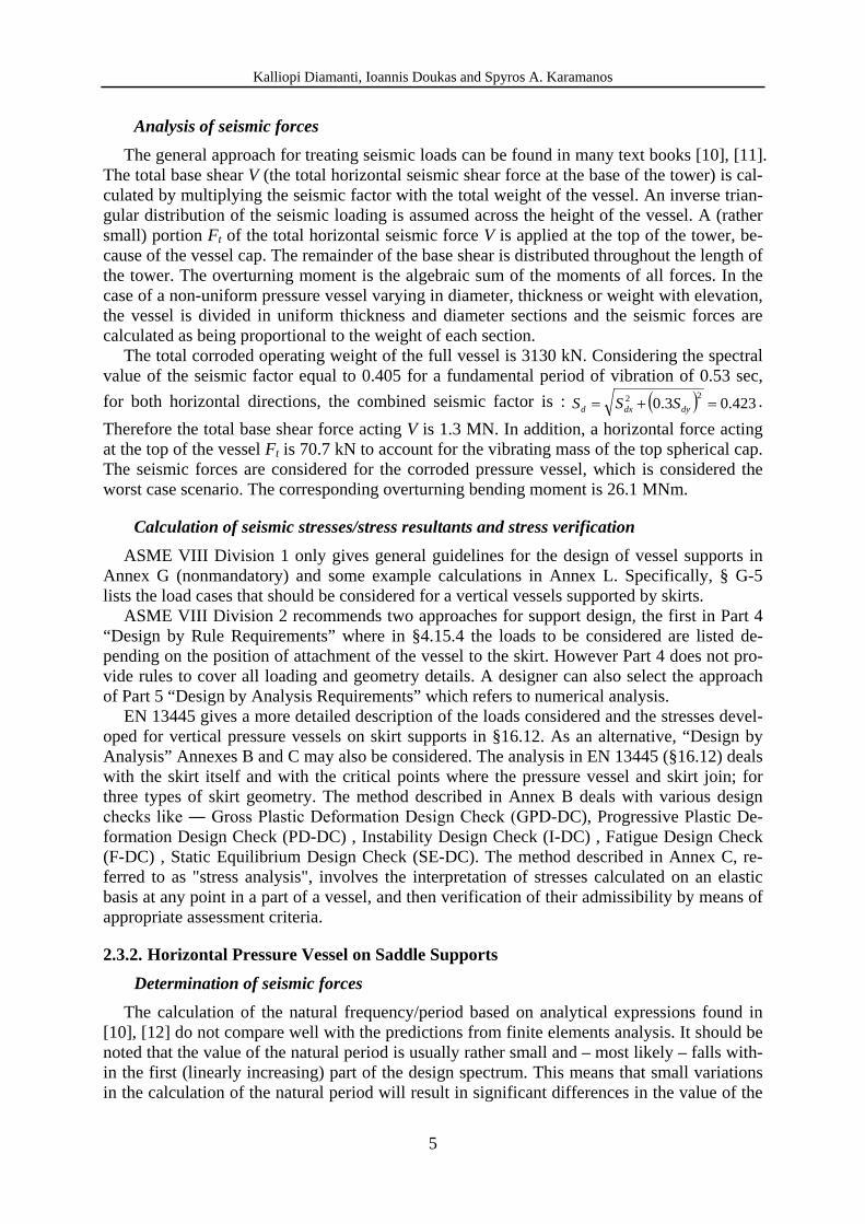
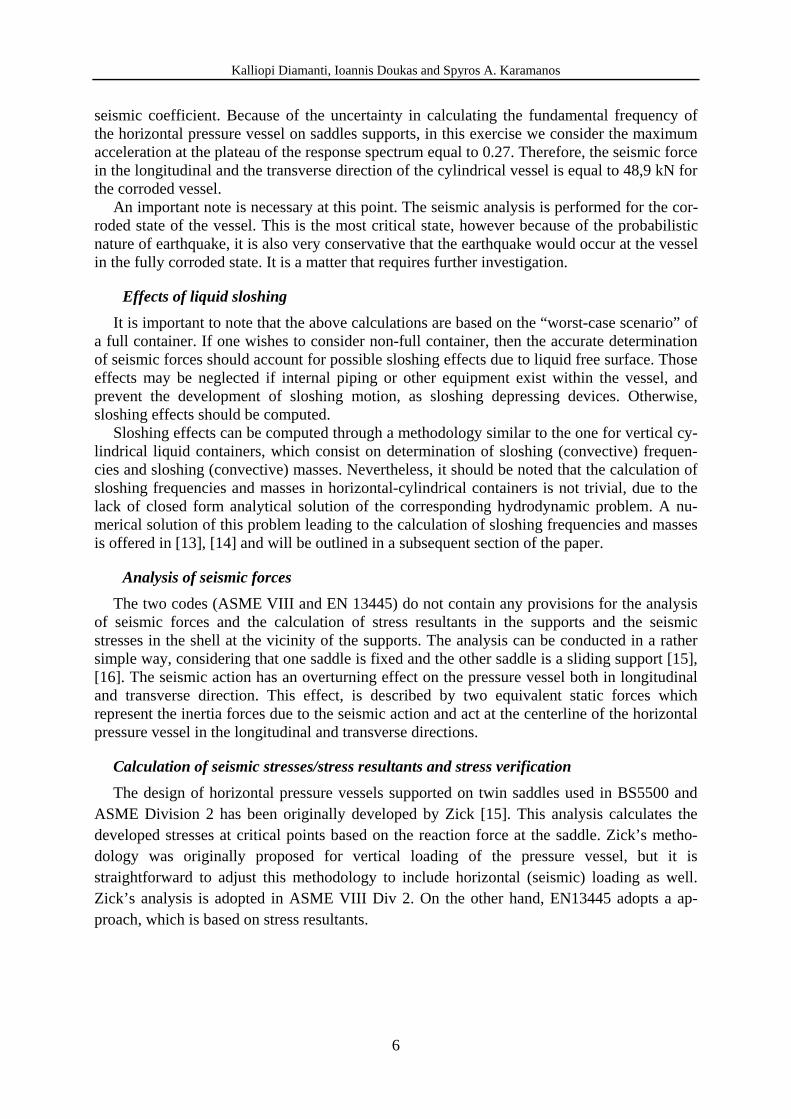
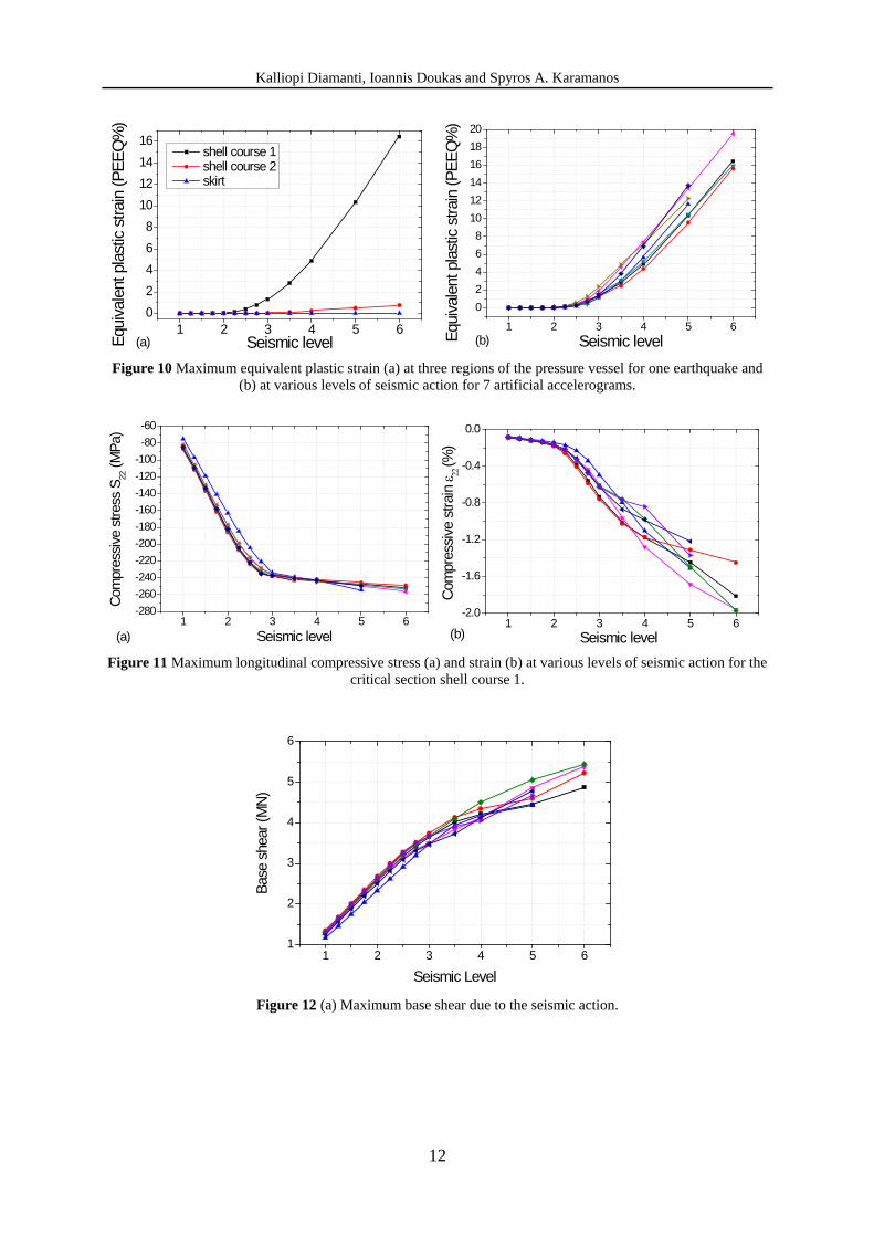
of seismic input is presented in the diagrams of Figure 9, Figure 10 and Figure 11 for the maximum von Mises stress, the maximum equivalent plastic strain and the maximum com-pressive stress and strain in the longitudinal direction, respectively. Finally, the reaction force (base shear) in terms of increasing level of seismic input is shown in Figure 12.
In order to estimate the q factor, two seismic input levels have to be identified in each of the response curves; (a) the level where transition from linear to non-liner behavior occurs (λe) and (b) the level at which a specific failure criterion is satisfied (λu). In this study, two differ-ent failure criteria, both in terms of strain, are specified as follows: Failure criterion 1 (Rupture of vessel wall): The equivalent plastic strain reaches a value equal to 0.4%. Failure criterion 2 (Buckling of vessel wall):
[18] The compressive strain in the longitudinal direc-
tion reaches a critical value defined by the following formula : 2
,22 30000025.05.0
+−=
EtpD
Dt
criticalε (1)
Furthermore, the previous pushover analyses have indicated that the critical location of the vessel is at the 1st (bottom) shell course, immediately above the skirt. At this location, the cor-roded thickness of the pressure vessel is 27 mm, and considering the vessel diameter (3100 mm) and its internal pressure 0.73 MPa, the critical value of compressive strain is equal to 0.24%. Using the above failure criteria, the estimated value of the q factor is given below in Table 1; the values are somewhat lower than the value of 2 suggested by ASCE 7.
Failure criteria 1 Failure criteria 2
λe 1.5 1.5 λu 2.5 2.25 q 1.7 1.5 Table 1 Estimated q factor using incremental dynamic analysis.
1 2 3 4 5 6
120
160
200
240
280
320
Von
Mise
s st
ress
(MPa
)
Seismic level
shell course 1 shell course 2 skirt
(a) 1 2 3 4 5 6
160
200
240
280
320
Von
Mise
s st
ress
(MPa
)
Seismic level(b) Figure 9 Maximum von Mises stress (a) at three regions of the pressure vessel for one earthquake and (b) at var-
ious levels of seismic action for 7 artificial accelerograms.
Kalliopi Diamanti, Ioannis Doukas and Spyros A. Karamanos
12
1 2 3 4 5 602468
10121416
Eq
uiva
lent
pla
stic
stra
in (P
EEQ
%)
Seismic level
shell course 1 shell course 2 skirt
(a) 1 2 3 4 5 6
02468
101214161820
Equi
vale
nt p
last
ic st
rain
(PEE
Q%
)
Seismic level(b) Figure 10 Maximum equivalent plastic strain (a) at three regions of the pressure vessel for one earthquake and
(b) at various levels of seismic action for 7 artificial accelerograms.
1 2 3 4 5 6-280-260-240-220-200-180-160-140-120-100-80-60
Com
pres
sive
stre
ss S
22 (M
Pa)
Seismic level(a)1 2 3 4 5 6
-2.0
-1.6
-1.2
-0.8
-0.4
0.0
(b) Seismic level
Com
pres
sive
stra
in ε 22
(%)
Figure 11 Maximum longitudinal compressive stress (a) and strain (b) at various levels of seismic action for the
critical section shell course 1.
1 2 3 4 5 61
2
3
4
5
6
Base
she
ar (M
N)
Seismic Level Figure 12 (a) Maximum base shear due to the seismic action.
Kalliopi Diamanti, Ioannis Doukas and Spyros A. Karamanos
13
4 HYDRODYNAMIC EFFECTS Pressure vessels contain liquefied gas, which may interact with the steel container in the
course of a strong seismic event and may cause hydrodynamic forces on the vessel wall, which should be taken into account in vessel seismic design.
For full containers, the entire liquid mass follows the motion of the container, and should be added to the container’s mass. On the other hand, if one wishes to consider the container not full, then the accurate determination of seismic forces should account for possible slosh-ing effects due to liquid free surface. Those effects may be neglected if internal piping or oth-er equipment exist within the vessel, which prevent the development of sloshing motion, acting as sloshing depressing devices. Otherwise, sloshing effects should be computed.
Detailed methodologies have been proposed to account for sloshing effects in vertical cy-lindrical liquid storage containers, which consist on determination of sloshing (convective) frequencies and sloshing (convective) masses. Those methodologies have been adopted by current design standards for liquid storage tanks (e.g. EN 1998-4 and API 650). Those provi-sions can be applied to vertical pressure vessels (stacks); however, the stacks are very tall, with very high value of aspect ratio H R , so that sloshing effects are negligible. Consequent-ly, for tall vertical cylindrical vessels, one may neglect sloshing effects and consider the entire liquid mass to vibrate with the flexible container.
On the other hand, in non-full containers of horizontal-cylindrical shape, hydrodynamic effects can be computed through a methodology similar to the one for vertical cylindrical con-tainers. Nevertheless, in liquid containers of horizontal-cylindrical shape, the calculation of sloshing frequencies and masses is not trivial, due to the lack of closed form analytical solu-tion of the corresponding hydrodynamic problem. A numerical solution of this problem lead-ing to the calculation of sloshing frequencies and masses is offered in [13], [14] and is summarized in the following.
Transverse direction The sloshing frequencies (in dimensionless form 2
nC R gω ) and the sloshing and impulsive masses nCM , IM respectively (normalized by the liquid mass nC LΜ Μ and I LΜ Μ ) of a hori-zontal-cylindrical container ( 1, 2,3,...n = ) are shown in Figure 13. It is noticed that only one sloshing mode is necessary for the seismic analysis, and that higher modes can be neglected. The total seismic force can be computed as follows
1 ( ) C C I gF S T A= +Μ Μ (2) where the impulsive mass contains the mass of the steel, and the impulsive motion is consi-dered as rigid so that the impulsive mass is multiplied by the peak ground acceleration gA .
Furthermore, ( )CS T is the spectral value corresponding to the sloshing period CT , which is equal to
1
2C
C
T πω
= (3)

Kalliopi Diamanti, Ioannis Doukas and Spyros A. Karamanos
14
-1.0 -0.6 -0.2 0.2 0.6 1.0liquid height parameter (e)
0
4
8
12
16no
rmal
ized
slosh
ing
frequ
encie
s
23 3 R gλ ω=
two-dimensionalcircular cylinder
22 2 R gλ ω=
21 1 R gλ ω=
-1.0 -0.6 -0.2 0.2 0.6 1.0liquid height parameter (e)
0.0
0.2
0.4
0.6
0.8
1.0
liqui
d m
ass
ratio
s
two-dimensionalcircular cylinder
kC
L
ΣMM
1C
L
MM
2C
L
MM
I
L
MM
Figure 13 Sloshing frequencies and masses for horizontal cylindrical container under transverse excitation.
Longitudinal direction The analysis presented in [13], [14] has shown that the dynamic behavior of a horizontal-
cylindrical container with longitudinal excitation can be approximated with an “equivalent rectangular container”. This equivalent rectangular container has the same free surface dimen-sions ( 2R L× ) and the same volume as the cylindrical container. This leads to the following expression for the height of the rectangular container:
( ) ( )( )( )
-1sin 1 21 12 2
eqH H RH R
R H R H Rπ − +
= − + −
(4)
The seismic force can be computed by equation (2), where only the first mode is consi-dered. Expressions for the sloshing frequencies and masses in the horizontal cylindrical ves-sels in the longitudinal direction are stated below in a normalized form, based on the corresponding expressions for rectangular containers (e.g. see [19]):
( ) ( )2 2 12 1tanhp eqR p Hp R
g L Lω ππ − −
=
p=1,2,3,… (5)
( )( ) 2 3
8 tanh 2 1
(2 1)eqpc
L eq
p H L
H L p
π
π
− =−
MM
, p=1,2,3,… (6)
5 CONCLUSIONS In this paper, the seismic analysis and design of two typical cylindrical steel pressure ves-
sels used in pertochemical facilities is presented (a) a vertical vessel on skirt and (b) a hori-zontal vessel on saddle supports. First, the provisions of EN 13445-3 and ASME B&PV code, section VIII, for these structures are summarised and important design issues, missing links and inconsistencies are discussed. It is the authors‘ opinion that more detailed information regarding the estimation of the behavior factor for these structures should be included in the design codes, as well as more detailed guidelines for the determination of the seismic forces. An attempt to estimate the behavior factor for these structures is presented using advanced numerical tools, for pushover analysis and incremental dynamic analysis. The pushover ana-

Kalliopi Diamanti, Ioannis Doukas and Spyros A. Karamanos
15
lysis indicated that the capacity of the presure vessels is quite higher than the required strength in seismic loading. On the other hand, using incremental dynamic analysis for the vertical-cylindrical pressure vessel, the value of behavior factor calculated is somewhat below the corresponding value suggested by American standard ASCE 7.
6 ACKNOWLEDGEMENTS This work was carried out with a financial grant from the Research Fund for Coal and Steel
of the European Commission, within INDUSE project: “STRUCTURAL SAFETY OF INDUSTRIAL STEEL TANKS, PRESSURE VESSELS AND PIPING SYSTEMS UNDER SEISMIC LOADING”, Grant No. RFSR-CT-2009-00022.
REFERENCES [1] EN 13445:2002 Unfired Pressure Vessels, European Committee for Standardization. [2] ASME Boiler & Pressure Vessel Code, Section VIII Rules for Construction of Pressure
Vessels, Division 1, The American Society of Mechanical Engineers, New York, 2007. [3] ASME Boiler & Pressure Vessel Code, Section VIII Rules for Construction of Pressure
Vessels, Division 2 - Alternative Rules, The American Society of Mechanical Engineers, New York, 2007.
[4] PD5500:2006 Specification for Unfired Fusion Welded Pressure Vessels, BSI British Standards, 2006.
[5] AD Merkblätter, Technical Rules for Pressure Vessels, Published by Verband der Tech-nischen Überwachungs-Vereine e.V., Essen, AD2000.
[6] Eurocode 8 – Design of Structures for Earthquake Resistance – Part 4: Silos, Tanks and Pipelines, EN1998-4.
[7] Eurocode 8 – Design of Structures for Earthquake Resistance – Part 1: General Rules, seismic actions and rules for buildings, EN1998-1.
[8] ASCE7-05, Minimum Design Loads for Buildings and Other Structures, Published by the American Society of Civil Engineers, 2006.
[9] 2010 PV Elite User Guide, COADE, Engineering Physics Software, Texas. [10] Guidelines for Seismic Evaluation and Design of Petrochemical Facilities, Published by
the American Society of Civil Engineers, 1997. [11] D. R. Moss, Pressure Vessel Design Manual, Elsevier, 3rd Edition, printed in U.S.A.,
2004. [12] W. C. Young, R. G. Budynas, Roark’s Formulas for Stress and Strain, 7th Edition, Mc
Graw Hill, 2002. [13] S. A. Karamanos, L. A. Patkas, and M. A. Platyrrachos, Sloshing Effects on the Seismic
Design of Horizontal-Cylindrical and Spherical Industrial Vessels., Journal of Pressure Vessel Technology, ASME, Vol. 128, No. 3, pp. 328-340, August 2006.
[14] S. A. Karamanos, D. Papaprokopiou, and M. A. Platyrrachos, Finite Element Analysis of Externally-Induced Sloshing in Horizontal-Cylindrical and Axisymmetric Industrial Vessels., Journal of Pressure Vessel Technology, ASME, Vol. 131, No. 5, Article Number: 051301, October 2009.

Kalliopi Diamanti, Ioannis Doukas and Spyros A. Karamanos
16
[15] L. P. Zick, Stresses in Large Horizontal Cylindrical Pressure Vessels on Two Saddle Supports, The Welding Journal Research Supplement, 1951.
[16] Pressure Vessel Design – Concepts and Principles, Edited by J. Spence and A.S. Tooth, E & FN Spon, 1994.
[17] ATC-40, Seismic Analysis and Retrofit of Concrete Buildings, Volume 1, Applied Technology Council, California, 1996.
[18] A. M. Gresnigt, Plastic Design of Buried Steel Pipelines in Settlement Areas, Heron, 31 (4), Delft, The Netherlands, 1986.
[19] R. A. Ibrahim, Liquid Sloshing Dynamics: Theory and Applications, Cambridge Uni-versity Press, 2005.