seepage failure, evaluation and remediation of penn forest dam · seepage failure, evaluation and...
TRANSCRIPT

SEEPAGE FAILURE,EVALUATION AND REMEDIATION
OFPENN FOREST DAM
by W. B. Bingham, P.E.lR. E. Holderbaum, P,E.*W. S. Sherman, P,E,3
ABSTRACT
Penn Forest Dam is a large earthfill embankment dam that impounds one of the City ofBethlehem’s two major water supply reservoirs. The dam is 145 feet high and 1,930 feet long andwas constructed between 1956 and 1958. On May 18, 1960, during the first filling of the reservoir,with the water level about 4.5 feet below spillway crest, a large sinkhole developed on the upstreamembankment slope, The reservoir was immediately lowered and repairs initiated, consisting ofbackfilling the sinkhole with earth and rockfill and grouting of the embankment and underlying rockfoundation. During the period 1969 to 1994, the reservoir was operated under the scrutiny of acontinuous and extensive instrumentation and monitoring program. In July 1994, with the reservoirlevel at spillway crest, piezometric levels recorded by instruments in the foundation rock in thevicinity of the former sinkhole area declined rapidly, indicating a potential dam failure. Emergencyresponse procedures were initiated and an extensive investigation was begun to evaluate thecondition of the dam and develop alternative remediation measures. Studies have concluded thatthe recommended alternative is the construction of an RCC replacement dam at an estimatedproject cost of $63.3 million.
PROJECT DESCRIPTION
Penn Forest Dam is a zoned earth and rockfillembankment dam with a central imperviouscore and a low concrete core wall founded onrock. The dam is approximately 1930 feetlong and 145 feet high. A concrete chutespillway is located in the right abutment and aconcrete intake tower is located on the leftabutment. Construction of the dam wascompleted in 1959, on Wild Creek, a tributaryto the Lehigh River, in northeasternPennsylvania. The dam is a large high-hazardstructure, Pennsylvania DEP Class A-1. PennForest is situated just upstream of Wild CreekDam, the other Bethlehem supply.
fL 1015SPILLWAY w
-------- ___
Typical Dam SectionPenn Forest Dam
1
2
3
Vice President, GANNETT FLEMING, INC.Senior Project Manager, GANNETT FLEMING, INC.Director of Public Works, City of Bethlehem,
149

HISTORICAL PERSPECTIVE
Penn Forest Dam was filled for the first time in 1959 and 1960. On May 18, 1960, with thereservoir at Elevation 995.5 (4.5 feet below the spillway crest), a sinkhole developed on theupstream slope of the embankment. Approximately one month prior to the development ofthe sinkhole, seepage had been observed exiting from a road cut in the downstream area andfrom weep holes in the spillway stilling basin. The leakage from the road cut was turbid andreported to be approximately 350 gpm. The sinkhole, which was reported to be on the orderof 15 feet in diameter and 15 feet in depth, was filled with approximately 100 cubic yards ofloosely placed silt and shale fragments. The fill placement had no measurable effect on theleakage, and the reservoir was subsequently lowered to Elevation 973.6, which is 26,4 feetbelow the spillway crest. Seepage reduced to approximately 90 gpm at that pool level.
Repairs to Penn Forest Dam were accomplished under the direction of D ‘AppoloniaAssociates between August and October 1960. The repairs consisted of grouting theembankment and the underlying rock foundation. During drilling, voids up to 18 inches indiameter were detected in the embankment. The embankment was grouted with surface-hydrated bentonite lumps and cellophane strips, and the rock was grouted with cement groutmixed in a ratio of 1:1 by volume, Upon completion of the grouting program, seepage fromthe road cut area was reported to be approximately 20 gpm with the reservoir atElevation 985.5,
Additional professional opinions were sought onthe condition of Penn Forest Dam and reportswere submitted in 1961 by B. K. Hough, and in1963 by Justin and Courtney and by GannettFleming, There was general concurrence thatthe failure mechanism was piping of theembankment materials into the fractured rockfoundation. The Hough and Justin and Courtneyreports pointed out numerous concerns about thedesign, the construction, and the repairs, andboth reports recommended that additionalprecautionary measures be undertaken. GannettFleming recommended that a controlled fillingprogram be used to further evaluate theconditions in Penn Forest Dam, with the results tobe used as a basis for determining the need foradditional repairs,
A controlled filling program was implemented in1964 after installation of an extensiveembankment and foundation instrumentationprogram. Water first reached the spillway crestlevel on October 3, 1969. Throughout the 5-yearfilling period there were indications of changes in
150

seepage conditions, but none which prevented completion of the filling or which were deemedto be of such magnitude as to require additional repairs,
Through the period of 1969 to 1995, a period of 26 years, monitoring of embankment andfoundation instrumentation has continued. Summary reports assessing the condition of PennForest Dam were prepared in 1975 and 1983. In both reports, ongoing changes in piezometriclevels were reported along with high but stable seepage flow rates. Throughout the 26-yearperiod, the scope of the monitoring program was scaled back. In recent history, themonitoring program includes reading approximately 184 instruments on a biweekly basis,including 5 seepage weirs and 2 seepage flumes, but only plotting the data for a group of49 instruments, weirs and flumes, that were considered to be key indicator instruments.
Through that same period, other activities that occurred in connection with Penn Forest Daminclude the following: Phase I Inspection under the National Dam Inspection Program in 1978;constructing an inverted filter over a concentrated seepage discharge point at the toe of thedam in 1982; performing a stability analysis for the downstream slope of the embankment in1986; constructing a toe drain system in the right abutment area and blanket drains onseepage areas on the downstream slope of the dam; and annual inspections of the dam andappurtenant features,
In July 1994, while the pool level was beingmaintained at spillway crest, piezometric levels in 1,010
instruments located in the foundation rock in the Pod ElevauwI
sinkhole area began to decline. The decline was “w —
masked for a period of time because a drawdown ~ ~. ——— ------ ..>\—
of the reservoir started at approximately the same \ ------... -Pm.157
time. The pool level dropped to about Elevation ~ =- = =. ~ . ...995 and was at that level for several months. S ‘>..<? J’ ‘--------------
Records show that piezometric levels in the # ’70— — ‘“ .\\
foundation rock continued to gradually decline H-=%-.““+. ‘ -+.-.
during that period. By November 1994, plotted--.....,=----
-. ,-.%piezometric records showed a sufficient decline in ’07 Ap. ~,, ,“. ‘JIJ. r.; ‘L ‘~cT--‘;;
7 instruments to warrant implementing19!44
precautionary measures, Overall, piezometricTIME
levels in the foundation rock in the vicinity of the original sinkhole declined approximately 10to 20 feet in the interval from July through November. The changes in the piezometric levelswere interpreted as a possible early warning sign of recurrence of piping, Subsequently, it wasbeen determined that a total of approximately 15 instruments in the general vicinity of thesinkhole area were affected to varying degrees. The additional 8 instruments that wereidentified as being affected include those for which data plots were not initially available andthose for which the declines are detectable but substantially smaller in magnitude.
151

In response to the observed conditions and the overall history of Penn Forest Dam, the Cityof Bethlehem implemented a series of emergency response measures recommended byGannett Fleming. The emergency response measures, summarized below, remained in effectuntil January 1995, at which time the pool level had been drawn down to approximatelyElevation 975. Following the emergency measures, the reservoir was further drawn down andheld at Elevation 950 during subsequent investigations,
● Penn Forest drawdown at 2 feet/day until pool level reaches Elevation 985
● Maximum achievable drawdown of Penn Forest if turbid flows, whirlpools, or major newseepage develops
● Wild Creek drawdown at achievable rates until 4 feet below spillway crest
● 24-hour visual surveillance of Penn Forest Dam
● Daily piezometer readings of 16 instruments in vicinity of original sinkhole area
● Daily weir readings
● Daily plotting of piezometer and weir data
● Bi-weekly readings of other piezometers
● Stockpiling of emergency supplies (geotextile and fill material) at damsite
● Setting and weekly monitoring of Elevation survey points on Embankment
● Notification of Corps of Engineers of conditions at the dam
● Notification of County Emergency Management personnel of conditions at the dam
● Implementation of other applicable provisions of the Emergency Action Plan
● Initiation of preliminary analysis of data and possible implications
● Designation of official spokesperson
The engineering investigations of the foundation and embankment have been performed byGannett Fleming, Inc., and reviewed by a Board of Consultants (BOC) comprised ofrecognized dam engineering experts, independently engaged by the City of Bethlehem,
Conclusions reached during the engineering investigations were documented in a reportprepared for the Board of Consultants, titled: “Study Findings and Conclusions - Penn ForestDam”. An abbreviated summaty of these conclusions is as follows:
F The original sinkhole failure at Penn Forest Dam was caused by a combination of designand construction defects that led to massive seepage and erosion of material from withinthe embankment.
152

E The repairs that were petiormed at Penn Forest Dam in 1960 were low cost, high riskrepairs that are not considered reasonable in terms of current engineering practice.
➤ The defects that caused the initial failure are still present and represent high long-term riskto Penn Forest Dam.
➤ Instrument data shows that conditions at Penn Forest Dam have changed both inmagnitude and location over the life of the dam. Deficient zones within the foundation andembankment are not limited to the original sinkhole area. The observed trends inperformance are interpreted as clear indications of seriously deteriorating conditions withinthe dam and foundation and warning signs of a developing dam failure.
F Satisfactory long-term performance of Penn Forest Dam cannot be expected without majorrepairs to the dam. The most fundamental requirement is that seepage through theembankment and foundation must be essentially eliminated. Repairs cannot be limited tothe sinkhole area, but must address the entire structure.
A total of nine options were considered for repairing, replacing, or removing the dam fromservice, These options are listed as follows:
> Grouting of the embankment and foundation of the dam using a variety of techniques.
F Partial removal and reconstruction of the dam.
➤ Installation of an impervious blanket and cutoff at the upstream toe of the dam,
➤ Installation of a concrete diaphragm wall through the center of the dam and extending intothe rock foundation,
➤ Removal of the existing dam and replacement with a new structure,
F Installation of a liner on the upstream embankment slope and a cutoff in rock at theupstream toe of the embankment.
F Removal of the existing dam and development of a new source of supply.
F Partial removal of the existing dam (lowered permanent pool) and development of a newsource of supply.
F Removal of the existing dam and raising of the pool level at Wild Creek Dam.
Based on an evaluation of the conditions at Penn Forest Dam, several of those options, orparts thereof, were not considered practical. The three options that merited final considerationwere:
153
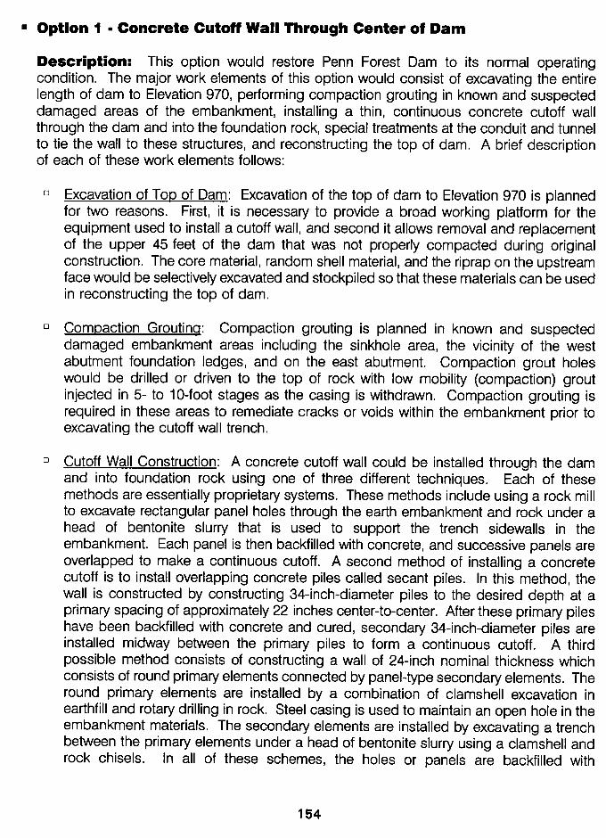
H Option 1 ■ Concrete Cutoff Waii Through Center of Dam
Description: This option would restore Penn Forest Dam to its normal operatingcondition, The major work elements of this option would consist of excavating the entirelength of dam to Elevation 970, performing compaction grouting in known and suspecteddamaged areas of the embankment, installing a thin, continuous concrete cutoff wallthrough the dam and into the foundation rock, special treatments at the conduit and tunnelto tie the wall to these structures, and reconstructing the top of dam, A brief descriptionof each of these work elements follows:
“ Excavation of TOD of Dam: Excavation of the top of dam to Elevation 970 is plannedfor two reasons. First, it is necessary to provide a broad working platform for theequipment used to install a cutoff wall, and second it allows removal and replacementof the upper 45 feet of the dam that was not properly compacted during originalconstruction, The core material, random shell material, and the riprap on the upstreamface would be selectively excavated and stockpiled so that these materials can be usedin reconstructing the top of dam,
❑ Compaction Groutinq: Compaction grouting is planned in known and suspecteddamaged embankment areas including the sinkhole area, the vicinity of the westabutment foundation ledges, and on the east abutment, Compaction grout holeswould be drilled or driven to the top of rock with low mobility (compaction) groutinjected in 5- to 10-foot stages as the casing is withdrawn, Compaction grouting isrequired in these areas to remediate cracks or voids within the embankment prior toexcavating the cutoff wall trench,
❑ Cutoff Wall Construction: A concrete cutoff wall could be installed through the damand into foundation rock using one of three different techniques. Each of thesemethods are essentially proprietary systems. These methods include using a rock millto excavate rectangular panel holes through the earth embankment and rock under ahead of bentonite slurry that is used to support the trench sidewalls in theembankment. Each panel is then backfilled with concrete, and successive panels areoverlapped to make a continuous cutoff. A second method of installing a concretecutoff is to install overlapping concrete piles called secant piles. In this method, thewall is constructed by constructing 34-inch-diameter piles to the desired depth at aprimary spacing of approximately 22 inches center-to-center. After these primary pileshave been backfilled with concrete and cured, secondary 34-inch-diameter piles areinstalled midway between the primary piles to form a continuous cutoff. A thirdpossible method consists of constructing a wall of 24-inch nominal thickness whichconsists of round primary elements connected by panel-type secondary elements. Theround primary elements are installed by a combination of clamshell excavation inearthfill and rotary drilling in rock. Steel casing is used to maintain an open hole in theembankment materials, The secondary elements are installed by excavating a trenchbetween the primary elements under a head of bentonite slurry using a clamshell androck chisels. In all of these schemes, the holes or panels are backfilled with
154

conventional or plastic concrete by the tremie method to displace the slurry and forma continuous concrete element. All three methods have the potential to providecomparable performance at similar schedules and costs.
❑ Reconstruction of TOD of Dam: After construction of the cutoff wall is complete thetop of dam would be reconstructed using the previously excavated material to thefullest extent possible. The replacement section would be a zoned embankmentcontaining a filter and drain. The top of dam will be raised to Elevation 1018.0 in thisoption to contain the PMF.
Preliminary details for this option are shown on Figure E.
Advantages and Disadvantages: The major advantages of this option are: (1) thisoption restores Penn Forest Dam to its normal operating level and provides additionalfreeboard to contain the PMF, (2) a partial, although minimal, pool may be maintained inPenn Forest Dam so long as difficulty with large slurry losses and hydrofracturing of theembankment are not experienced during excavation for the cutoff wall, and (3) a cofferdamwould not be required to implement this option.
Two major disadvantages of this option are: (1) case history documents indicate thatcutoff walls constructed through embankment dams have resulted in large slurry lossesand additional damage to the embankments due to hydrofracturing. Large change ordersand construction delays are common due to the need for additional grouting to addressthe slurry losses and/or hydrofracturing; and (2) the cutoff constructed under this optionis not accessible for post-construction inspection, Repairs, however, could be made bygrouting if defects could be located. Further, drainage downstream of the cutoff wall, tocollect seepage through the wall, cannot be provided. Cutoff wall defects would beconcealed and might be difficult to locate and repair,
■ Option 2- Embankment Liner and Foundation Cutoff
Description: This option consists of restoring Penn Forest Dam to its normal operatingcondition by installing a liner system on the upstream slope of the dam and a cutoff intothe foundation rock at the upstream toe of the dam. The liner system and cutoff would beinterconnected at a drainage gallery at the upstream toe of the dam. Other major elementsof this option include excavation and backfill of the sinkhole area, compaction grouting inknown and suspected damaged areas of the embankment, special treatment at the tunnelto tie this structure to the cutoff, and installation of a cofferdam and associated diversionworks. Option 2 is shown on Figure F, A brief description of each of the major workelements follows:
❑ Liner Svstem: Four liner materials were considered for installation on the upstreamslope: steel, concrete, hydraulic asphalt, and synthetic materials. Steel is the highestcost liner option and, for that reason, was quickly eliminated from consideration. Abrief description of the other three materials is as follows:
155

Cross Section of Option 1
1020
990
960
810
7s0
Concrete Cutoff Wall Through Dam
i TOP OF DAM EL. 1015>-,-. . – 020TEMPORAFWWORKING PLATFORM
– 990
2.5- 960
——___4_— T—— ——p’— _______ !
smos~ MUOSTONE MUOSTONEEXISnNG GROUT CURTNN+ S#NDSTONE - 810
DSTONE
MUOSTONE ~ Muo=oNE- 700
75~4;5 _~ _:w-300 -2s0 -200 -l!XI -lIXI .50 0
I+50 +4W +150 +2Lm +250 +300 +350 +400 +:2?
Figure E
Cross Section of Option 2
Liner with Grout Curtain
Figure F156

● Hvdraulic AsRhalt: Although hydraulic asphalt has been used for lining dams andreservoirs for about 60 years, recent use of asphalt on dams in the United States hasbeen limited, The technology of hydraulic asphalt for dam construction, however, iswell developed but has been utilized more frequently in California and overseas. Thematerials are suitable for use with potable water supplies, The equipment andmaterials required for this type of construction are not unusually specialized,however, procedures for paving on a relatively steep slope are not commonlypracticed by local contractors. Suitable construction equipment and an experiencedlabor force for installing an asphalt liner on a dam slope may be limited in theEastern United States. Hydraulic asphalt has sufficient impermeability to essentiallyeliminate seepage through the embankment. Asphalt also exhibits some flexibility,allowing it to tolerate minor movements of the embankment that commonly occurduring normal filling cycles,
➤ Concrete: Concrete is the most common material used for lining the upstream slopeof embankment dams. Although it has been used on numerous dams in the UnitedStates in the past, its use at the current time is limited. However, the technology iswell developed and installation of concrete linings does not require unusuallyspecialized equipment or labor force. The main disadvantage of concrete is itsbrittleness. The permeability of concrete is sufficiently low to essentially eliminateseepage through the embankment although some minor, but acceptable, leakagewould occur through minor cracks and defects in the waterstopped joints.
b Svnthetic Liner: Use of synthetic liners on embankment dams has been relativelylimited. However, synthetic liners have been used extensively on concrete dams andlandfills in the past 10 years, thereby advancing the technology of this class ofmaterials, The impermeability and flexibility of this type of material is excellent,provided it is installed correctly. However, the material is fairly fragile and could besubject to damage during installation, In contrast to asphalt and concrete, asynthetic liner must be covered with protective layers of earth and rock materialsand, therefore, would not be accessible for routine inspection or repair.
Of the three materials, the synthetic liner and hydraulic asphalt are believed to have thelowest cost, Concrete is estimated to have the highest cost, Regardless of the typeof material selected for the liner system, a drainage system should be installed betweenthe liner and embankment to collect any seepage through the liner and from surfaceinfiltration and groundwater entering behind the liner from the abutments andembankment. Seepage from the drainage system would be routed to a drainagegallery constructed in the foundation rock at the upstream toe of the dam, Thedrainage gallery would also be used to collect seepage in the foundation rockintercepted in drilled drain holes located downstream from the foundation cutoff.
❑ Foundation Cutoff: Several methods are available for constructing the cutoff in the rockfoundation at the upstream toe of the dam, Two options have been investigated for
157

Penn Forest Dam: a conventional grout curtain and a concrete cutoff wall. The cutoffwall could be constructed with any of the methods described in Option 1.
“ Compaction Grouting: Compaction grouting similar to that described for Option 1would also be used for this option. The purpose of the grouting would be tostrengthen weak areas in the embankment so that sufficient support is provided for theliner system.
Advantages and Disadvantages: The major advantages are: (1) this option restoresPenn Forest Dam to its normal operating level, (2) the design incorporates drainsdownstream of the liner and cutoff systems to safely collect and monitor seepagebypassing these systems, and (3) both the liner and cutoff systems are accessible forinspection and repair, if needed. The primary disadvantage of this option is the reservoirwould be completely lowered during construction. A cofferdam located upstream of thework area, however, would permit stream flows into the reservoir to be released throughthe 48-inch conduit into Wild Creek with minimal contamination. A second disadvantageis that the liner system relies on the existing embankment for its support, Theinvestigations conducted to date have revealed the presence of voids and soft materialswithin the dam. All of these deficiencies may not be detected and repaired by theproposed compaction grouting. As a result, remedial repairs of the liner and/or cutoff maybe required in the future to assure successful performance of the dam.
■ Option 3- Roller=Compacted Concrete Replacement Dam
Description: This option consists of constructing a roller-compacted concrete (RCC)gravity dam approximately 460 feet upstream of the centerline of the existing earthembankment dam. The alignment of the RCC gravity dam is such that it can make full useof the existing spillway and outlet works, This option is shown on Figure G. The majorcomponents of this option are as follows:
❑ RCC Gravitv Dam: The RCC gravity dam will be buttressed on the downstream faceby earth material from the existing embankment. The earthfill buttress allows the basewidth of the gravity section to be slightly reduced in comparison to the base width fora concrete gravity dam. This reduction in section reduces the quantities required forfoundation excavation and preparation and for roller-compacted concrete.
The gravity dam would be founded on firm rock. A conventional grout curtainpenetrating through the foundation rock will serve to reduce potential for underseepage.A synthetic liner embedded in precast panels on the upstream face of the structurewould serve to prevent seepage through the structure. Drains would be provided forboth the foundation and the dam to control and monitor seepage and uplift pressuresacting on the base of the dam, Drains would also be effective in controlling porepressures between RCC lift layers,
158

Typical Section for Option
RCC Replacement Dam
3
Figure G
Figure H159

The drains would be connected to adrainage gallery located near the base of thestructure. Any seepage collected in the drainage gallery could be discharged to theexisting concrete diversion conduit. The drainage gallery also provides access to thefoundation of the dam should any remedial foundation grouting become necessaryduring the life of the dam.
❑ Existina Alm.rtenances: The RCC gravity dam is positioned upstream of the existingembankment in order to replace the embankment while still making use of the existingappurtenances. The existing spillway and outlet works would remain in service for thisoption, The existing spillway approach walls would be raised 3 feet to increase thespillway capacity to the PMF, The existing 12-foot-diameter concrete diversion conduitwould be modified to maintain its service as a low-level outlet for the reservoir, Onlyminor repairs are planned for the existing intake tower,
❑ Stream Diversion Durina Construction: Since the new gravity dam is located upstreamand in the reservoir area of the existing embankment dam, complete drawdown of theexisting reservoir would be necessary during construction of this option, Facilities fordiversion of streamflows for an extended period of time would also be required. Thesefacilities would be similar to those previously described for Option 2.
Advantages and Disadvantages: The major advantages are: (1) this option restoresPenn Forest Dam to its normal operating level; (2) the proposed RCC gravity section relieson the existing embankment for only minimal support such that a minor failure of theembankment section, even though highly unlikely, would not have a significant impact onthe overall performance of the dam and (3) this option has the most certainty for a longservice life with minimal maintenance, The primary disadvantage of this option is that thereservoir would be completely lowered during construction. A cofferdam located upstreamof the work area, as previously described for Option 2, would permit streamflows into thereservoir to be released through the 48-inch conduit into Wild Creek with minimalcontamination,
SELECTION OF REMEDIAL OPTION
The estimated total project costs for the three options are:
■ Option 1 -$77,4 million
■ Option 2 -$58.5 million■ Option 3 -$64.8 million
Option 1 has several drawbacks related to constructibility and performance. Excavation of thewall without damaging the embankment while penetrating hard sandstone layers in thefoundation are of particular concern. Option 2 relies on the existing embankment for all of itssupport which is suspect. While Option 3 is more costly than Option 2, it does not rely on theexisting embankment for satisfactory performance. Cost is only one of several importantconsiderations in selecting an alternative. The certainty with which a repair of the dam can beachieved is also important. When considering the overall advantages and disadvantages,
160

costs, risks, and project life, the City of Bethlehem determined it was in their best long-terminterest to elect Option 3 and construct a new RCC replacement dam.
The City of Bethlehem has implemented Option 3 and authorized the design and constructionof a new RCC replacement dam. It is expected that the new dam will be completed in 1998at an estimated construction cost of $45.4 million. The dam will be 160 feet high and1960 feet long and will contain approximately 380,000 cubic yards of roller-compactedconcrete. Penn Forest Dam will be the third largest (by volume) RCC dam in the United Statesand the largest east of the Mississippi.
The Authors would Iike to express their appreciation to the Bethlehem Authority (Owner of theproject), and the City of Bethlehem (Operator of the Water System) for their support andcooperation throughout the project, and the following individuals at Gannett Fleming, Inc., whocontributed directly to the preparation of this paper through preparation of exhibits, and wordprocessing:
Carol A. Burleson . . . . . . . . Word Processing
Michael G. Liddick . . . . . . Exhibit Preparation
Paul G. Schweiger . . . . . . . . . . . . . Data Plots
161