see attached - panama canal...
TRANSCRIPT

PANAMA CANAL AUTHORITY
1. REQUEST FOR PROPOSAL No.:
RFP-76161
5. ISSUED BY.
PANAMA CANAL AUTHORITY Employer's Representative Locks Project Management Division Building 740, Corozal Panama, Republic of Panama
6. NAME AND ADDRESS OF CONTRACTOR (INCLUDE PHYSICAL & POSTAL ADDRESS)
Grupo Unidos por el Canal, SA Building 22B, Brujas Road Cocoli, Republic of Panama
9. VARIATION:
VARIATION
2. CONTRACT No. :
CMC-22 1427
PAGE 1 OF 6 3. 0ATE: January 25, 2012
4. VARIATION No.: 27
7. CONTRACTOR'S TELEPHONE NUMBER:
507-3 16-9900
8. CONTRACTOR'S FACSIMILE NUMBER:
(8] The con tract referred to in item No. 2 is hereby varied as set forth in item 10, entitled ~DESCRIPTION OF VARIATIOW.
[8] YES. D NO. The contractor sha ll send a copy, duly signed, of this Variation to the Employer's Repre sentative/Contracting Officer.
9 A. THIS VARIATION IS EXECUTED ON THE BASIS OF: (Specily Iile legal au/ilorily).
THE VARIATION DESCRIBED IN ITEM 10 IS HEREBY INCORPORATED AND MADE A PART OF THE CONTRACT.
9 B. THE CONTRACT REFERRED TO IN ITEM NO. 2, IS VARIED TO INCORPORATE ADMINISTRATIVE CHANGES (such as Ihe paying office, account numbers, etc.) .
9 C. THIS BILATERAL AGREEMENT IS SIGNED AND INCORPORATED INTO THE CONTRACT REFERRED TO IN ITEM X NO. 2 OF THIS FORM, ON THE BASIS OF: (Specify tile legal authority) Volume III , Conditions of Contract , Sub-
Clause 1.16 [Entire Agreement]. 4th Paragraph
9 D. OTHER. (Specify mallller ami the legal aulhorily) .
9 E. ACCOUNT NUMBER (II required):
10. DESCRIPTION OF THE VARIATION (L ist III accordance Will, Ille Older of file Contracl. If add/llonal space IS reqlllred, use blank slleels).
See attached
Except for the variatlon(s) herein speci fi ed, all other terms and conditions of the Contract remain unchanged.
11 . NAME AND TITLE OF THE PERSON AUTHORIZED 12. NAME AND TITLE OF THE EMPLOYER'S TO SIGN (Type or prilll) REPRESENTATIVEICONTRACTING OFFICER(Type or prilll)
Bernardo Gonzalez Jorge de la Guardia, Employer's Representative
14. DATE: 16. DATE:
(Employers epresell alIVe on mg Officer's siglla/ure)

Variation No. 27 January 25, 201 2 Design and Construction of the Third Set of Locks
Variation No. 27 is issued to incorporate the following changes:
2 of 6
1. Volume II, Part 2, Section 01 81 36.13 [O&M Bldgs. & Facil. ·Space Programming]· Delete Paragraph 1.03 G.1 and replace it with the following:
"1. At each lock complex, locate the maintenance building [MB] on the I·Side as follows:
a. Pacific lock complex on the upper·levellock wall. b. Atlantic lock complex on the lower· levellock wall." (RFV·103)
2. Volume II, Part 2, Section 26 50 00 [Lighting Systems]· Delete Paragraph 1.04 C.2 and replace it with the following:
a. The Contractor shall design and specify an illumination system to provide illumination to the dark pockets that are produced all along both sides of a large wide ship hull (starboard and pod) and the walls of the chamber and down to the water level. The illumination shall permit the ship pilot to have a clear visual reference to correctly assess the position of his ship hull in relation to the walls of the locks and the water level. The lighted reference area may be discrete or continuous, along the chamber wall. For the plllpose of the required calculations the Contractor shall use the Design Vessel descdbecl in Subparagraph 1.02 A. of Section 01 10 00 (General Project Requirements), with zero reflectance from the ship sides.
b. The water shall be illuminated at a minimum of 5 discrete locations along each chamber wall. The maximum distance between discrete illumination points shall be 100111. An acceptable location is at each stair shaft. At each shaft, niches shall be provided for the installation of two fixtures, one on each side of the ladder. Minimum illumination level shall be 30 lux at low water level in front of the stair's shaft to a distance of 3 meter from the chamber wall to the center of the chamber.
c. The top fenders shall be illuminated by providing a continuous niche along the chamber wall for locating the light fixtures. The maximum distance between fixtures shall be 15 meters, equally spaced Wiring shall not be installed exposed inside the continuous niche. The span of fender illuminated to the point that the light level reaches 30 luxes, on both side of a fixture, shall not be less the 4 meter. The design shall consider ease and safe accessilJility from land for lamp replacement and lens cleaning. Lamp and ballast replacement shall not impact lane availability or cause delays. Equipment/tools required for accessing the fixtures for maintenance fJlIIposes shall be provided at each lock complex.
d, At low water level the area where the illumination level is "5" lux or less shall not exceed 2. 10 meters, measured from chamber wall towards the center of the chamber. Calculations shall ass Ime a maxim height of 13.04m between the top of wall and the low water level, and can include the contdbution from high mast

Variation No. 27 3 of 6 January 25, 2012 Design and Construction of the Third Set of Locks
poles located on the same wall where the lights are located but shall assume no light contribution from the high mast poles locateel on the opposite wall. High mast poles shall not be locateel closer than 6 meter from the edge of the chamber.
e. With no ship in the chambe/; the illumination inside the chamber, at the water level, shall have an average illumination not less than 30 lux oliginating from the high mast lighting installation.
f. The operator in the Main Control Building [CB} shall be able to remotely control the illuminated area to on-off. Matelials used to construct the chamber lighting fixture housing, shall not proeluce spal1(s if contacted or collided with by a vessel or other obstruction. Construction of this system will be by the Employer. "
(RFV-093)
3. Volume II, Part 2, Section 26 50 00 [Lighting Systems]- Delete Paragraph 1.04 C.9.b and replace it with the following:
"b. Light fixture enclosure shall be classified explosion proof, as Class 1 Division 2, Groups A, B, C, or D, as elefined in the NFPA-70. The letters indicate the gas or vapor in the hazarelous location. The light fixture type shall be suitable for outdoor installation. Lighting fixtures shall be cast aluminum housing or corrosion-free, high impact, glass-reinforced, UV-staiJi/izeel nylon. Lamp source type anel wa ttage shall be coorelinated between the Contractor anel Employer. " (RFV-093)
4. Volume II, Part 2, Section 33 11 00.13 [Water Utility Main Lines]- Delete Paragraph 1.03.J and replace it with the following:
"J. At the Atlantic Site, the permanent relocation of the 12-inch water mains that will be elisturbeel by the wor/(, including the stretches through the Crossunelers, shall be accomplished using 16-inch DIP Class 250 pipes. Tempo/my relocation of the 12-inch water main, passing through the natural Plug at the No/th Side of the Site, may be accomplished using 12-inch PVC pipe." (RFV-092)
5. Volume II, Part 2, Section 35 12 00 [Vessel Detection Systems (VDSs)] - Delete Paragraph 1.03.F.4 and replace it with the following :
"4. Shall be in accordance will) Section 40 91 00 (Plima/y Process Measurement Devices)." (RFV -107)
6. Volume II, Part 2, Section 40 91 00 [Primary Process Measurement Devices]Add Paragraph 1.03.B.16.c as follows:
7.
"c. Unless approved by the Employer 's Representative, ingress protection of VDS sensors shall be IP67 or bel/er." (RFV-107)
Volom. II, p", 2, s.~ 91 00 [P";m"y P,o,"" M"",,·,,"OO' 0"''"'1'
Variation No. 27 January 25, 2012 Design and Construction of the Third Set of Locks
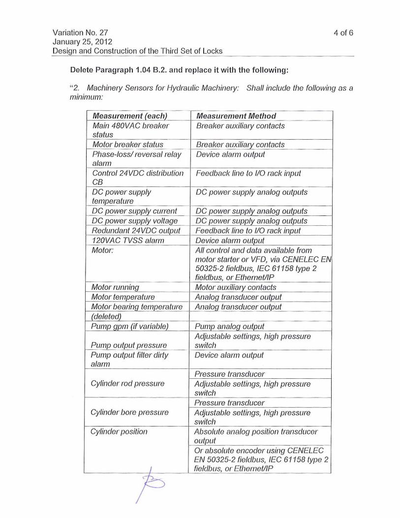
Delete Paragraph 1.04 B.2. and replace it with the following:
4 of 6
"2. MachinefY Sensors for Hydraulic MachinefY: Shall include the following as a minimum:
Measurement (each) Measurement Method Main 480VAC breaker Breaker auxiliafY contacts status Motor breaker status Breaker auxiliafY contacts Phase-iossl revefsal relay Device alarm output alarm Control 24 VDC distribution Feedback line to 110 rack input CB DC power supply DC power supply analog outputs temperature DC power supply current DC power supply analOG outputs DC power supply voltage DC power supply analog outputs Redundant 24VDC output Feedback line to 110 rack input 120VAC TVSS alarm Device alarm output Motor: All control and data available from
motor statter or VFD, via CENELEC EN 50325-2 fieldbus, IEC 61158 type 2 fieldbus, or EthemetllP
Motor runninG Motor auxiliafY contacts Motor temperature Analog transe/ucer output Motor bearing temperature Analog transducer outlJut (deleted) Pump gpm (if variable) Pump analog output
Adjustable settings, high pressure Pump output pressure switch Pump output filter difty Device alarm output alarm
Pressure transducer Cyline/er rod pressure Adjustable settings, high pressure
switch Pressure transe/ucer
Cylinder bore pressure Acljustable settings, high pressure switch
Cylinder position Absolute analog position transducer output Or absolute encoder using CENELEC EN 50325-2 fieldbus, IEC 61158 type 2
I fiele/bus, or EthemetllP
~

Variation No. 27 January 25, 201 2
5 of 6
Design and Construction of the Third Set of Locks Measurement (each) Measurement Method
Or resolver using analog transducer output Deceleration inductive proximity switch (open) Stop inductive proximity switch (~en)_
Deceleration inductive proximity switch (close) Stop inductive proximity switch (close) Shut off valve limit switches
Shut off valve position Directional valve limit switches Directional valve position (Reserved) Proportional valve (Reserved) position Reservoir oil Level Analog transducer output Reservoir oil temp Analoq transducer output Moisture I water in oil Analog transducer output or PLC Oil patiicle counter compatible protocol Local gate open alarms Discrete output Local qate closure alarms Discrete output
(RFV-089)
8 . Volume II, Part 2, Section 40 96 45 [Process Control Softwarej- Delete Paragraph 1.03 A. 6 and repl ace it with the following:
"6. PLC programming shall use the most adequate combination of IEC 611 31-3 compliant languages and shall support hyperlinks and the latest versions of extensible markup language (XML) and hypertext markup language (HTML)."
(RFI - 394)
9. Volume II, Part 2, Section 40 96 45.13 [Process Control Software for LMCSsjDelete Paragraph 1.04 D.7.a and replace it with the following:
"a. This display shall show in the case of a hydraulic machine, the animated hydraulic schematic represented by pressure lines (red) and connection to tan/( lines (blue) as well as pilot pressure (light red) and pilot tan/( lines (light blue). Pump suction lines (yellow) shall also s/JOw. Lines shall be light gray or white if excluded from pressure side or tan/( connection, by valves. One or more pressure gauges shall show the roel side and bore side pressures and the reselvoir oil level shall also be animated to reflect the propotiional level in relation to cylinder extension. In the case of variable flow pumps, the arrow in the pump symbol shall be animated to reflect real-time pump flow. In the case of proportional valves, the valve shall have a schematic symbol. All solenoid valves shall be animated 10 ' hili In ",,-11m, """" r "nk lin" ",,1/ ol" ng' In w i", 10 " 1/, ,,

Variation No. 27 6 of 6 January 25, 2012 Design and Construction of the Third Set of Locks
hydraulic circuit state. Pressure and limit switches shall also be animated, see Figure 40 96 45.13- 17." (RFV -089)
10. Volume II, Part 3, Section 01 33 00 [Submittal Procedures]- Delete Paragraph 1.04 K and replace it with the following:
''I( Copies for the Employer's Representative: Unless otherwise speci fi ed, upon the release of the Contractor's Documents for construction, the Contractor shall provide 6 half size (Size C) copies to the Employer's Representative, for Employer use during the Works."
11 . There is no time or cost impact to the Locks Contract as a consequence of this Variation.