security-related information -withhold under 10 cfr …
TRANSCRIPT

SECURITY-RELATED INFORMATION - WITHHOLD UNDER 10 CFR 2.390George T. HamrickDoke Vice PresidentEnergye Harris Nuclear Plant5413 Shearon Harris Rd
New Hill NC 27562-9300
919-362-2502
Ref: 10 CFR 50.54(f)
November 27, 2012Serial: HNP-12-119
U.S. Nuclear Regulatory CommissionAttn: Document Control Desk11555 Rockville PikeRockville, MD 20852
Subject: Shearon Harris Nuclear Power Plant, Unit No. 1 Response toRecommendation 2.3 Seismic Walkdown of the Near-Term Task ForceReview of Insights from the Fukushima Dai-ichi Accident
Reference: Request For Information Pursuant to Title 10 of the Code of FederalRegulations 50.54(f) Regarding Recommendations 2.1, 2.3, and 9.3 of theNear-Term Task Force Review of Insights from the Fukushima Dai-ichiAccident, Dated March 12, 2012
Ladies and Gentlemen:
By letter dated March 12, 2012, the Nuclear Regulatory Commission (NRC) issued aRequest for Information (Reference) requesting licensees to provide informationregarding Recommendation 2.3 (Seismic) to support the evaluation of the NRC staffrecommendations for the Near-Term Task Force (NTTF) review of the accident at theFukushima Dai-ichi nuclear facility.
By this letter, Carolina Power & Light Company (CP&L) submits the Shearon HarrisNuclear Power Plant, Unit No. 1 response regarding the performance of seismicwalkdowns to identify and address degraded, non-conforming or unanalyzed conditionsand to verify the current plant configuration with the current seismic licensing basis.
The information provided herein and the activities described in this report are consistentwith the guidance provided by the Electric Power Research Institute's (EPRI) 2012Technical Report 1025286 titled, "Seismic Walkdown Guidance for Resolution ofFukushima Near-Term Task Force Recommendation 2.3: Seismic."
Enclosure 1 to this letter provides the requested information.
Enclosure 2 to this letter contains the Shearon Harris Nuclear Power Plant, Unit No. 1management signatures documenting site management review of this document.
Attachments 6 and 7 of Enclosure 1 of this letter contain
SECURITY-RELATED INFORMATION - WITHHOLD UNDER 10 CFR 2.390
Upon removal of Attachments 6 and 7 from the Enclosure, this letter is decontrolled. ik

Serial: HNP-12-119 Page 2
CP&L requests that Attachments 6 and 7 of the Enclosure to this letter, which containsecurity-related information, be withheld from public disclosure in accordance with10 CFR 2.390.
If you have any questions regarding this submittal, please contact Mr. Dave Corlett,Supervisor- Licensing/Regulatory Programs, at (919) 362-3137.
I declare under the penalty of perjury that the foregoing is true and correct. Executed onNovember 27, 2012.
Sincerely,
Enclosure 1: Seismic Walkdown SubmittalEnclosure 2: Report Review by Site Management
cc: Mr. J. D. Austin, NRC Sr. Resident Inspector, HNPMs. A. T. Billoch Col6n, NRC Project Manager, HNPMr. V. M. McCree, NRC Regional Administrator, Region II
Attachments 6 and 7 of Enclosure 1 of this letter contain
SECURITY-RELATED INFORMATION - WITHHOLD UNDER 10 CFR 2.390
Upon removal of Attachments 6 and 7 from the Enclosure, this letter is decontrolled.

ENCLOSURE 1SEISMIC WALKDOWN SUBMITTAL
CAROLINA POWER & LIGHT COMPANY
SHEARON HARRIS NUCLEAR POWER PLANT, UNIT NO. 1DOCKET NO. 50-400
RENEWED LICENSE NO. NPF-63
SHEARON HARRIS NUCLEAR POWER PLANT, UNIT NO. 1 RESPONSE TORECOMMENDATION 2.3 SEISMIC WALKDOWN OF THE NEAR-TERM TASKFORCE REVIEW OF INSIGHTS FROM THE FUKUSHIMA DAI-ICHI ACCIDENT.

Shearon Harris Nuclear Power Plant Seismic Walkdown Report
1.0 Introduction .... ........................................................ 2
2.0 Seism ic Licensing Basis ................. ........................................................................................... 2
3.0 Personnel Qualifications .............................................................. 3
3.1 Equipment Selection Personnel ............................................ 3
3.2 Seism ic W alkdown Engineers ................................................................................................. 4
3.3 Licensing Basis Reviewers ...................................................................................................... 5
3.4 IPEEE Reviewers .......................................................................................................................... 5
3.5 Peer Reviewers ................................................................... ..................................................... 5
4.0 Selection of SSCs ............................................................................................................................. 5
4.1 SW EL 1 Development .................................................................................................. ......... 5
4.2 SW EL 2 Development ........................................................................................................... 8
5.0 Seism ic W alkdowns and Area W alk-Bys ....................................................................................... 9
5.1 Seism ic W alkdown Methodology ............................................................................................. 9
5.2 Area W alk-By Methodology ...................................................................................................... 10
5 .3 R e s u lts ........................................................................................................................................ 1 1
5.4 Maintenance Assessment ...................................................................................................... 11
5.5 Planned or Newly Installed Protection or M itigation Features ............................................... 11
5 .6 In a c c e s s ib le Ite m s ...................................................................................................................... 1 1
6.0 Licensing Basis Evaluations ............... ........................................ 12
7.0 IPEEE Vulnerabilities Resolution Report .................................................................................... 12
8.0 Peer Review Report ........................................................................................................................ 12
Attachment 1: Base List 1
Attachment 2: SWEL 1
Attachment 3: Base List 2.
Attachment 4: Rapid Drain-Down List
Attachment 5: SWEL 2
Attachment 6: Seismic Walkdown Checklists
Attachment 7: Area Walk-By Checklists
Attachment 8: Peer Review Report
Enclosure 1, Page 1

Shearon Harris Nuclear Power Plant Seismic Walkdown Report
1.0 Introduction
The Nuclear Regulatory Commission (NRC) has issued a Request for Information pursuant to Title 10 ofthe Code of Federal Regulations 50.54(f) (hereafter 50.54(f) letter) regarding "Recommendations 2.1, 2.3,and 9.3 of the Near-Term Task Force (NTTF) review of insights from the Fukushima Dai-lchi Accident"resulting from the Great Tohoku Earthquake and subsequent tsunami. This submittal report, pursuant tothe NRC's request for information, is offered to address the scope associated only with the 50.54(f) letterEnclosure 3, NTTF Recommendation 2.3 Seismic. Specifically, this report provides information for theShearon Harris Nuclear Power Plant (HNP) regarding the performance of seismic walkdowns to identifyand address degraded, non-conforming or unanalyzed conditions and to verify the current plantconfiguration is consistent with the current seismic licensing basis. The information provided herein andthe activities described in this report are consistent with the guidance provided by the Electric PowerResearch Institute's (EPRI) 2012 Technical Report 1025286 "Seismic Walkdown Guidance: ForResolution of Fukushima Near-Term Task Force Recommendation 2.3: Seismic." The NRC, in its letterdated May 31, 2012, endorsed the EPRI guidance document.
There were 114 areas walked down and 46 areas walked by. The 2.3 Seismic Walkdown inspectionsperformed were primarily non-intrusive visual inspections of primarily plant Seismic Category I systems,structures, and components (SSCs). During the inspections observed degraded, nonconforming, orunanalyzed conditions were identified and addressed through the corrective action program (CAP).Based on the EPRI guidance document, the list of SSCs for inspection were to be obtained through asystematic selection process to establish a random while broadly populated Seismic WalkdownEquipment List (SWEL). The SWEL was made up of two separate lists. SWEL 1 included SSCs fromvarious locations throughout the plant and SWEL 2 included a shorter list of Spent Fuel Pool (SFP) SSCs.
This selection process for the SSCs combined with the inspection checklist attributes assessed thedesign basis seismic capabilities of the plant. These attributes pertain to SSC anchorage, interaction andother considerations based on NRC and industry insights of the Fukushima Dai-lchi Accident.
A similar past seismic effort includes the Individual Plant Examination for External Events (IPEEE)program. Many of -the same SSCs inspected for the IPEEE were re-inspected for the current 2.3 SeismicWalkdowns. Most of the SWEL items originated from the IPEEE Safe Shutdown Equipment List (SSEL).The IPEEE program used Seismic Margins programs to assess the plants capabilities to perform properlyto a larger Review Level Earthquake (RLE) and modifications were performed if needed.
The 2.3 Seismic Walkdown inspections were performed to visually check the material condition of theSSCs and its anchorage to meet its seismic design basis. Also inspected are the surrounding equipmentand area for interactions with other SSCs, fire hazards, water spray, and housekeeping issues that mayinteract with the SSCs. Conditions found were recorded on the developed checklists and evaluated. Anycondition that was a potential adverse seismic condition (PASC) was further evaluated for its ability tomeet its seismic design basis requirements and put into the plant CAP. In addition to checking the SSCswith respect to their design basis, this report discusses the general adequacy of licensee monitoring andmaintenance procedure by reviewing walkdown observations.
2.0 Seismic Licensing Basis
The Seismic Licensing Basis found in the HNP Updated Final Safety Analysis Report (UFSAR) and otherdesign documents provides the protection and mitigation features to assure that the SSCs perform theirimportant to safety function both during and after a Safe Shutdown Earthquake (SSE). The developmentof the site characteristics, earthquake characteristics, the seismic design requirements for SSCs and thevarious codes and standards used for seismic designs at HNP are summarized below.
Site characteristics are identified in the UFSAR Section 2. All seismic category I buildings structuralfoundations are reinforced concrete mats, founded on suitable rock or concrete fill. The natural gradearound the plant is approximately 260 feet above mean sea level. The area of the plant was excavated toan approximate elevation of 234 feet for the shallowest part to 179 feet for the deepest level.
Enclosure 1, Page 2

Shearon Harris Nuclear Power Plant Seismic Walkdown Report
Seismic Design is found in Section 3.7 of the UFSAR and was based on an Operating Basis Earthquake(OBE) with a horizontal ground acceleration of 0.075g, and SSE with horizontal ground acceleration of0.15g. The vertical and horizontal ground accelerations associated with the OBE and SSE werenormalized to 0.15g for the SSE and 0.075g for the OBE. The response spectrum was developed fromthe strong motion record of the 1935 Helena, Montana earthquake.
Design of Seismic Category I structures is found in UFSAR Section 3.8. The design of safety-relatedstructures, equipment and safety related piping is found in UFSAR 3.9. Stress and deformation behaviorof safety-related structures, piping, and equipment were maintained within the allowable limits whensubjected to loads such as dead, live, pressure, and thermal, under normal operating conditionscombined with the seismic effects resulting from the response to the SSE and OBE. These allowablelimits are defined in appropriate design standards such as the ASME Boiler and Pressure Vessel CodeSection III, ASME III Division II/ACI 359 (Winter '75 Addendum), ASME III, Division 1, Subsection NE,(Winter 1971 Addendum); American National Standards Institute (ANSI) B31.1.0 for Power Piping; ACI318-1971, ACI 349-1976 Appendix C, ACI 349-1980 Appendix B, and American Institute of SteelConstruction (AISC 1970/1971). The stresses that resulted from normal loads and design basis loss-of-coolant accident loads combined with the response to the SSE were limited so that no loss of functionoccurred and the capability of making a safe and orderly plant shutdown was maintained.
Seismic Category I Instrumentation and Electrical Equipment seismic design is described in UFSARSection 3.10. The equipment must perform their safety function before, during and after a seismic event.The standard for seismic testing of equipment is Institute of Electrical and Electronics Engineers (IEEE)344-1971. For equipment purchased after March 1, 1977, IEEE 344-1975 is applicable. Class 1Eequipment and supports meet IEEE 323-1974.
3.0 Personnel Qualifications
3.1 Equipment Selection Personnel
3.1.1 Billy Alumbaugh
Billy R. Alumbaugh is a Registered Professional Engineer and has over 30 years engineeringexperience including 16 years nuclear experience with site experience working for a utility and asa consultant. Progressive experience in civil engineering ranges from individual contribution tosupervisory and project management. Supervised multiple engineers at operating nuclear facilityand was involved in several projects including: Control Room expansion, Equipmentobsolescence, Dry Fuel Storage, and Containment redesign/design pressure uprate. Trainingreceived includes Auxiliary Operator, Waste Control Operator, Systems Training, 10CFR50.59certification, and modification/change control. As a consultant, he served as the Civil/StructuralEngineering Design Lead for the new plant Design Certification and Combined Operating Licenseprojects providing a technical review of civil based licensing responses to clients or the NRC andproject management. More recently served as the Civil-Structural-Architect Discipline Managerfor the detailed design phase of the US-APWR including all aspects of the design including thesite specific and Design Control Document seismic evaluations. Billy Alumbaugh has an MS anda BS degree in Civil Engineering.
3.1.2 Primo Novero
Mr. Novero has over 46 years of engineering experience, with 40 years in structural design, fourin construction, and two in environmental. He has 34 years of nuclear structural designexperience in various structures, systems and components involving different materials, and indiverse topical matters including seismic. Primo Novero has a BS in Civil Engineering andEnvironmental Engineering, and is a Registered Professional Engineer in the field of Civil,Structural and Environmental.
Enclosure 1, Page 3

Shearon Harris Nuclear Power Plant Seismic Walkdown Report
3.1.3 Mike Weber
Mr. Weber has worked at the Harris plant since 1983 and held various positions within theOperations organization including Reactor Operator; Senior Reactor Operator, Control RoomSupervisor, Nuclear Shift Manager, and Superintendent - Operations Support. He currentlyholds an active Senior Reactor Operator license on the Harris Plant.
3.1.4 Brad Morrison
Mr. Morrison has over 30 years of experience in nuclear power and has held varioussupervisory/management positions including Instrumentation & Control, Engineering Scheduling,Maintenance Surveillance Test Group, Outage & Scheduling, Nuclear Assessment and Materials& Contract Services, Additionally, he served as the Functional Area Manager responsible foroverall fleet outage planning, performance, and execution. He has also served as Shift OutageManager during four refueling outages including steam generator replacement outages.
3.2 Seismic Walkdown Engineers
3.2.1 Jose Olmeda
Mr. Olmeda has over 30 years of experience in the Analysis and Design of nuclear relatedfacilities, components structures and systems. This includes the use of Industry Standards andcodes as: ACI-318, ACI-349, AISC-ASD/LRFD, SEI/ASCE-7, ASCE-4-98, ASCE-43-05,ANSI/AISC N690, NFPA-17, and the Life Safety Code. He has a high degree of knowledge of thetheory and applications of finite elements using structural analysis and design software such asGT-Strudl, STAAD.Pro2007 and other common design software in the structural engineering field.He is a longstanding member with the American Concrete Institute, American Institute of SteelConstruction, and a Charter Member of the Structural Engineers Institute of the American Societyof Civil Engineers. Mr. Olmeda maintains an Associated Membership in the ACI-118 Committee,Use of Computers for Concrete Applications.
3.2.2 Les Galazka
Mr. Galazka has over 30 years of leadership/project management experience, includingengineering. He has twenty-six years of nuclear experience including Structural, Mechanical,Piping and Pipe Support, Start-up, Nuclear Waste Process and Management, and SystemEngineering. He has six years of international experience on construction, equipment installationand testing, QC, engineering and management. He holds a Bachelors and a Masters inMechanical/Structural Engineering.
3.2.3 Harold Bamberger
Harold Bamberger has over 40 years of experience in both field and office functions required fordesigning, analyzing, and installing piping and pipe supports for metallic and non-metallicsystems in major power, chemical, and pharmaceutical facilities. Mr. Bamberger has worked forvarious nuclear power plants in design and review of piping, piping supports and other nuclearstructure using ASME Section III, ASME/ANSI B31.1 and B31.3, and applicable nuclear plantprocedures. Mr. Bamberger is a Registered Professional Engineer and holds an AD inMechanical Engineering Technology with additional classes in Mechanical Engineering andTechnology.
3.2.4 Nazir Sheikh
Mr. Sheikh is a Registered Professional Engineer and has over 35 years engineering experiencewith over 30 years nuclear experience. Mr. Sheikh has been associated with nuclear design innuclear piping design, concrete and steel structures using ACI 318, ACI 349, AISC, mechanical
Enclosure 1, Page 4

Shearon Harris Nuclear Power Plant Seismic Walkdown Report
electrical equipment qualification and testing in accordance with IEEE-344. Nazir Sheikh has aBS in Civil Engineering and studies toward a MS in Mechanical Engineering.
3.3 Licensing Basis Reviewers
3.3.1 Harold Bamberger
See 3.2.3 above
3.4 IPEEE Reviewers
3.4.1 Harold Bamberger
See 3.2.3 above.
3.4.2 Jose Olmeda
See 3.2.1 above.
3.5 Peer Reviewers
3.5.1 Louis Wade
Louis Wade has over 30 years experience in Quality Assurance/Quality Control (QA/QC), ProjectManagement, and QA/QC consulting. Over 15 years in management positions associated withconstruction, maintenance, modifications, including work package control, and operation of DOEand NRC regulated facilities such as nuclear power plants, vitrification facilities, radioactive wastefacilities, gaseous diffusion facilities, and TRU waste chacterization and disposal. Mr. Wade is anASQ Certified Quality Auditor 10600, Lead Auditor per ANSI N45.2.23, and Lead Auditor perASME-NQA 1.
3.5.2 David Dickinson
Mr. Dickinson has 40 years experience in the engineering profession as a civil/ structuralengineer on a variety of projects. Experience includes both office and field assignments withcontractors and engineering consulting firms on nuclear power generation, industrial andpetrochemical projects. He has extensive experience in the structural analysis, seismicequipment qualification, foundations, support of heavy equipment, rigging and cranes, heavy lifts,and modifications to existing buildings and structures for nuclear power stations.
4.0 Selection of SSCs
4.1 SWEL 1 Development
The selection of SSCs included in SWEL 1 for HNP was based on the guidance provided in EPRIGuidelines, Section 3. Plant staff participated in the SSC selection process and concurred with theSSCs selected for SWEL 1 and SWEL 2. The inspection of items on this list addresses safeshutdown and containment integrity at the plant. This selection process was conducted byexperienced personnel and plant operations staff members selecting SSCs based on the EPRIGuidance using screening selection criteria. These screens are listed as follows:
" Screen #1: Seismic Category I
" Screen #2: Equipment or systems NOT regularly inspected
* Screen #3: Supports five safety functions
o Reactor reactivity control
o Reactor coolant pressure control
Enclosure 1, Page 5

Shearon Harris Nuclear Power Plant Seismic Walkdown Report
o Reactor coolant inventory control
o" Decay Heat Removal
o Containment function
Screen #4: Sample considerations (systems, major new/replacement, equipment types,environments, IPEEE enhancements)
The list of equipment resulting from Screen #3 is Base List 1. At HNP, the Base List 1 was created assuggested by the EPRI guidance document, through the use of a previous equipment list fromimplementation of the IPEEE Seismic program. Per EPRI 1025286, the first screen narrows the list toSSCs classified as Seismic Category I items because only those have a defined seismic licensingbasis against which to evaluate the as-installed configuration. The second screen further narrows thelist by selecting only those remaining items that do not have regular inspections to confirm theirconfiguration is consistent with the licensing basis. The third screen ensures that those remainingitems are associated with at least one of the five safety functions.
Once Base List 1 was established, Screen #4 was applied to ensure the inspections encompassed abroad and varying array of equipment. Screen #4 included selection considerations compiled from theEPRI guidance document and from the 50.54(f) letter Enclosure 3. This resulted in the creation ofSWEL 1. Considerations made for the creation of SWEL 1 are detailed in the sections below.
4.1.1 Equipment types/classes
One of the sampling objectives was to select items from all equipment classes where possible.
Clas's Base ListN o'. Equipment Included I Total Selected
0 Other 13 5
1 Motor Control Centers and Wall-Mounted Contactors 15 7
2 Low Voltage Switchgear and Breaker Panels 4 2
3 Medium Voltage Metal-Clad Switchgear 2 1
4 Transformers 8 3
5 Horizontal Pumps 17 6
6 Vertical Pumps 1 1
7 Pneumatic-Operated Valves 10 4
8 Motor-Operated and Solenoid Operated Valves 82 10
9 Fans 4 0
10 Air Handlers 4 2
11 Chillers 2 1
12 Air Compressors 4 0
13 Motor Generators 0 0
Enclosure 1, Page 6

Shearon Harris Nuclear Power Plant Seismic Walkdown Report
Class Base ListNo. Equipment Included I Total Selected
14 Distribution Panels and Automatic Transfer Switches 14 7
15 Battery Racks 2 1
16 Battery Chargers and Inverters 6 3
17 Engine Generators 2 1
18 Instrument Racks 106 35
19 Temperature Sensors 0 0
20 Instrument and Control Panels 2 1
21 Tanks and Heat Exchangers 39 10
Total 337 100
There were four (4) Class 9 items,. Diesel Generator Fans and four (4) Class 12 items, DieselStarting Air Separators, listed on the SSEL. All eight of these items were found to be declassifiedas Seismic Category 1 equipment due to modifications to the diesel air starting system since theIPEEE effort. Check valves were added to the diesel air staring system causing the Class 9 and12 items to declassified as Seismic Category 1. The added check valves were included in SWEL1 and are shown in Attachment 2. Upon searching the HNP Equipment Database (EDB), therewere no SC 1 (Quality Group A) Fans or compressors that satisfied the safety function criteria setforth by EPRI, and therefore they screened out.
4.1.2 Five safety functions
The appropriate proportion of SSCs serving each of the five safety functions on Base List 1 wasmaintained in the selection of SSCs for the SWEL 1 as follows:
Safety Function Base List I SSCs Selected SSCs
Reactor reactivity control 112 59
Reactor coolant pressure control 127 73
Reactor coolant inventory control 126 68
Decay heat removal 172 91
Containment function 95 43
This table demonstrates full coverage of the five safety functions for the selected SSCs. Base List1 in Attachment 1 includes the safety function category of each SSC.
4.1.3 Locations
The items selected for inclusion on the SWEL 1 are from a variety of plant locations including theReactor Auxiliary Building, Diesel Generator Building, Containment Building and Service WaterBuilding, among others. SWEL 1 in Attachment 2 includes the building location of each SSC.
Enclosure 1, Page 7

Shearon Harris Nuclear Power Plant Seismic Walkdown Report
SSCs from a variety of environments including dry and hot, wet and cold, mild and harsh, andinside and outside buildings were included for inspection in the SWEL 1. SWEL 1 in Attachment 2includes the environment of each item.
4.1.5 Systems
During the SWEL 1 selection process, consideration was given to equipment of varying systemsincluding the Chemical Volume Control, Auxiliary Feedwater, Main Steam, and Residual HeatRemoval Systems. Table B-1 of Appendix E "Safety Function-System Matrix for PWRs" of theEPRI guidance was consulted to ensure systems to support safety functions were included.Additionally, equipment in the Service Water System that support access to the Ultimate HeatSink was included in SWEL 1. SWEL 1 in Attachment 2 includes the system of each SSC.
4.1.6 Risk
Risk was considered in the selection of the SSCs from the SSEL list for items to include in theSWEL 1. The selection team was able to readily identify items that posed a higher risk rankingdue to their knowledge and experience working at nuclear plants. Such items as emergencydiesels, station batteries, core cooling systems, emergency cooling water systems, and 1Eelectrical switchgear are identified as critical equipment that have a higher risk and associatedconsequences. These equipments were included while maintaining a balance with the otherrequirements of selecting SWEL equipment.
4.1.7 IPEEE vulnerabilities
HNP had 13 IPEEE vulnerabilities of which six were selected for inclusion on SWEL 1. Particularattention was paid to these items during the walkdowns and no discrepancies were identified. TheIPEEE vulnerabilities are indicated on SWEL 1 in Attachment 2.
4.1.8 Modified, replacement, and new equipment
Modifications to the plant including new and replacement equipment was considered whendeveloping the SWEL.
4.1.9 Accessibility
Though a limited numbers of SSC's were found to have anchorage conditions obscured bymaterial such as insulation, cables, etc. none were found to be inaccessible during the scheduledevaluation period. An entry into the containment area was made and the SWEL items withinevaluated. Cabinets with handles latches or thumb screws were opened and observed. Openingcabinets that would cause equipment inoperability or cabinets without handles, latches, orthumbscrews were omitted from the group that required opening.
4.2 SWEL 2 Development
The SWEL 2 selection process started with the list of Safety-Related components listed with the SFPsystem number. The starting list satisfied the first screen. The equipment selection engineers thenassigned an equipment class to the remaining items. This equipment class was used to satisfyscreens 2 since a variety of equipment and system types were selected. Screen 3 was satisfied byselecting items that are walkdown appropriate and in a variety of areas. Base list 2 was completedafter the equipment number was assigned and items in the In Service Inspection(ISI) program were removed. The equipment classes were used to ensure a variety of types ofequipment would be included, similar to the way it was done for SWEL 1. There was no previousinspection data, so a realistic distribution was achieved by the equipment selection personnel.
Enclosure 1, Page 8
Shearon Harris Nuclear Power Plant Seismic Walkdown Report
Rapid Drain-Down added 4 valves in filtration and purification lines below the pool. These pipingsystems are not seismic category I so they were not present on base list 2. The lines the valves areon are located at elevations such that a failure would cause a rapid drain down. The gates separatingthe pools were not added to the inspection since they are considered structures and per the EPRIguidance (Ref. 2) structures need not be considered. The pools are full during normal operation soeven if a gate failed, it would not cause a rapid drain down. The pool skimmer cannot drain the poolenough to qualify as a rapid drain down risk due to the limited length of hose attached to it. TheDrain-Down List is located in Attachment 4. These items were added to selected items from Base List2 to create SWEL 2, which is included in Attachment 5.
5.0 Seismic Walkdowns and Area Walk-Bys
The methodology used to complete the walkdowns and area walk-bys complies with the EPRI guidance.The walkdowns and area walk-bys were performed by the SWEs listed in Section 3.2. The SWEs usedengineering judgment, based on their experience and training, to identify PASCs. Walkdown results weredocumented on the Seismic Walkdown Checklists and area walk-bys on Area Walk-By Checklists. TheseChecklists are provided as Attachments 6 and 7, respectively.
5.1 Seismic Walkdown Methodology
Seismic walkdowns were performed on each item in SWEL 1 and SWEL 2. The walkdown effortincluded an investigation of the SWEL equipment for potentially adverse seismic conditions (PASC).,PASC's include adverse anchorage conditions, adverse seismic spatial interactions and any otheradverse seismic condition concerning the equipment. When deficiencies and PASC's were identifiedduring the inspection, they were documented with a description of the condition on the SeismicWalkdown Checklist (SWC). The Seismic Walkdown Engineers (SWEs) made judgments based ontheir evaluation and experience regarding the acceptability or lack thereof of the equipmentanchorage. These observations were documented on the checklist for that item.
Seismic walkdowns were performed on each SWEL 1 and 2 and were evaluated for adverseanchorage conditions, adverse seismic spatial interactions, or other adverse seismic conditions asdetailed below.
5.1.1 Adverse Anchorage Conditions
Lack of anchorage or inadequate anchorage has been the primary cause for malfunction andfailure of equipment during an earthquake. During the walkdown inspection, the anchorage wasinspected against specific design details for approximately 50% of the SWEL items that includeanchorage.
For all SWEL items with anchorage, a general visual inspection of anchorage was performed to
determine if the SSC had indications of the following:
e Bent, broken, missing, or loose hardware
* Corrosion that is more than mild surface oxidation
o Visible cracks within 10D of an anchor
o Gaps that may exist at the visible parts of the equipment foundation
o Other potential adverse concerns
Enclosure 1, Page 9

Shearon Harris Nuclear Power Plant Seismic Walkdown Report
In cases where the anchorage was inaccessible and a substitution was not possible, an alternatemethod was used to assess potential degraded, non-conforming, or unanalyzed conditions whichincluded:
" An review of previous walkdown packages to validate prior inspection attributes foradequacy
" A determination whether the local environment could cause the degradation of
anchorage or its installation, (e.g. adverse environment conditions):
o Evidence of moisture or relatively high humidity,
o Evidence of corrosion on other nearby components and
o Anchorage, and/or indication of vibration that could loosen the fasteners.
• A check whether the equipment and its anchorage have been subjected tomaintenance or modified since it was last walked down
The SWEs used engineering judgment to assess whether the anchorage is potentially vulnerableto seismic failure or malfunction. The basis for any judgment used in the assessment wasdocumented in the seismic walkdown checklists.
5.1.2 Adverse Seismic Spatial Interactions
Seismic spatial interaction is the physical interaction between the SWEL item and a nearby SSCcaused by relative motion between the two during an earthquake. The walkdown included aninspection of the adjacent and surrounding areas to each SWEL item for adverse seismicinteraction conditions could occur that would affect the capability of the item to perform itsintended safety-related functions. The three types of seismic spatial interaction effects consideredwere: proximity to an item, failure of an SSC and falling on an item, and flexibility of attachedlines impacting an item.
5.1.3 Other Adverse Seismic Conditions
in addition to adverse anchorage and spatial interaction conditions, other potentially adverseseismic conditions that could challenge the adequacy of SWEL items were also identified whenpresent, such as:
" Degraded conditions
** Loose or missing fasteners that secure internal or external components to equipment
" Large, heavy components mounted on a cabinet that are not typically included by theoriginal manufacturer
• Cabinet doors or panels that are not latched or fastened
5.2 Area Walk-By Methodology
The focus of the area walk-bys was to identify potentially adverse seismic conditions associated withother SSCs located in the vicinity of the SWEL item (either within the room or for large rooms withinapproximately 35 feet from the item). The key examination factors that were considered included:anchorage conditions, significantly degraded equipment in the area, a visual assessment ofcable/conduit raceways and HVAC ducting, housekeeping items that could cause adverse seismicinteraction, seismically induced fire and flooding/spray interactions as described below.
Enclosure 1, Page 10

Shearon Harris Nuclear Power Plant Seismic Walkdown Report
5.2.1 Seismically Induced Fire Interactions
The occurrence of a seismic event could create fire in multiple locations, simultaneously degradefire suppression capabilities, and as a result prevent mitigation of fire damage to multiple safety-related functions.
During the seismic walkdown, the engineers visually assessed any potential sources of fire (e.g.,compressed flammable gas bottles, fuel tanks, other combustible material, -etc.) located in thevicinity of the SWEL item to ensure it was adequately restrained.
5.2.2 Seismically Induced Flooding/Spray Interactions
Seismically induced flooding events can potentially cause multiple failures of safety-relatedsystems. Two examples of two potential sources of flooding are rupture of piping and vessels.Instances of concern include threaded fire protection piping, sprinkler head impact, flexibleheaders and stiff branch pipes, non-ductile mechanical couplings, seismic anchor motion andfailed supports.
As the SWEs performed the walkdowns, they visually assessed the potential sources of water(e.g. fire suppression piping, tanks, etc.) located in the vicinity of the subject SSC to ensure they.had adequate support throughout the load path and, therefore, were not likely to be a source offlooding or spray that could adversely affect the subject item of equipment. The items that wereidentified as potential conditions were documented. Any assessment and disposition of theeffects- were documented with the subject item.
5.3 Results
When conditions were identified during t he inspection that were not readily determined as acceptable,they were documented along with an evaluation of the condition using available design informationand based on the SWEs experience. SSCs may have been determined to be a non-PASC or PASCat the time of the inspection, or the condition may have been documented and further discussioncompleted before determining if it is a PASC. Non-PASC conditions found during the inspections arethose evaluated and determined to not affect the ability of the item to perform its intended safetyfunction during or after design basis ground motion as noted in the Current Licensing Basis. No SSCswere identified during the walkdowns or walk-bys as a PASC.
5.4 Maintenance Assessment
During the process of conducting the Fukushima Seismic 2.3 area walk-bys there were multipleinstances noted where area plant lighting fixtures were attached utilizing "S" hooks. These fixturesare typically installed in a manner that the "S" hooks attached to the fixture are open and couldtheoretically become disconnected in the course of a seismic event. All open "S" hooks wereevaluated for consequences of failure and determined to be acceptable. A Nuclear Condition Reporthas been initiated to conduct an extent of condition investigation and address the open the "S" hooks.During the walkdowns, relatively few and minor housekeeping problems were noted andcontamination was minimal. These indicators suggest that monitoring and maintenance processesand procedures are adequate.
5.5 Planned or Newly Installed Protection or Mitigation Features
There were no items determined to be potentially adverse seismic conditions (PASCs). Thereforethere were no planned or newly installed protection or mitigation features.
5.6 Inaccessible Items
No items were found to be inaccessible, and all SWEL items were inspected.
Enclosure 1, Page 11

Shearon Harris Nuclear Power Plant Seismic Walkdown Report
6.0 Licensing Basis Evaluations
As no PASCs were identified, the SSCs inspected would have been capable of fulfilling their intendedsafety function.
7.0 IPEEE Vulnerabilities Resolution Report
The results of,the IPEEE report are summarized in a table below. These items were closed betweenNovember of 1994 and February of 1997 with the exception of the final item in, the table below. Thisitem's disposition was confirmed; however, the specific closure date could not be ascertained. With theexception of "S" hooks as stated in Section 5.4, the configuration management program has maintainedadequate control of the required features.
'Equipment Description Action'
Diesel generator control panel Close both ends of the S-hooks on the hanging fluorescent lights inthe DG control room
Diesel generator control panel Close both ends of the S-hooks on the hanging fluorescent lights inthe DG control room
Insulation cabinets in Reactor The row of fluorescent lights needs to be relocated on the existing
Auxiliary Building unistrut three inches to the west away from the cabinets
Train A Auxiliary Relay Panel Install missing mounting screw for relay
Train B Auxiliary Relay Panel Install three missing mounting screws for relay
Motor Control Center Replace missing latch on breaker panel door
Motor Control Center Replace missing latch on breaker panel door
Motor Control Center Replace missing latch on breaker panel door
Instrument Panel Replace three missing access panel screws and replace twomissing latches for breaker panel door
Instrument Panel Replace three missing access panel screws
RHR heat exchanger temp U-bolt has slipped off top of pipe and needs to be reworkedswitch
Instrument rack Close both ends of the S-hooks on the hanging fluorescent lights inthe DG control room
Electric motor operated valve Compressed gas cylinder adjacent to valve needs to be removed orrestrained in accordance with AP-003
8.0 Peer Review Report
The Peer Review Report is included in Attachment 8.
Enclosure 1, Page 12

Shearon Harris Nuclear Power Plant Unit I Seismic Walkdown Report
Enclosure 1 Attachments
Attachment 1:
Attachment 2:
Attachment 3:
Attachment 4:
Attachment 5:
Attachment 6:
Attachment 7:
Attachment 8:
Base List 1
SWEL 1
Base List 2
Rapid Drain-Down List
SWEL 2
Seismic Walkdown Checklists
Area Walk-By Checklists
Peer Review Report

Shearon Harris Nuclear Power Plant Unit I Seismic Walkdown ReportAttachment 1: Base List I
Attachment1: Base List I
5 pages

Shearon Harris Nuclear Power Plant Unit I Seismic Walkdown ReportAttachment 1: Base List I
Generic ID from E.0SSEL Feature C C C " %So 0 W
0 0 0
1A23-SA Motor control center 1A23-SA X X X X1A-SA 6.9KV switchgear 1A-SA X X X X X1EA-14 Solenoid valve X X X X X1EA-15 Solenoid valve X X X X X1EA-29 Solenoid valve X X X X X1EA-45 Solenoid valve X X X X X1EA-61 Solenoid valve X X X X X1B-SA Diesel Generator Fan E-86 (1B-SA) X X X X X1A-SA Water chiller unit (WC-2) X X X X X
1 B-NNS Diesel starting air compressor, 1 B-NNS X X X X X1A-SA Diesel A generator control panel, 1DG-E036 X X X X X
DP1B1-SB Distribution panel for vital DC 1B1-SB X X X X X1B-SB Vital batteries in rack (1B-SB) X X X X X1B-SB Solid state battery charger (1B-SB) X X X X X1B-SB Diesel Generator 1B-SB X X X X X
LS-2464A-SA Day tank level switch HH X X X X XMCB Main control board X X X X XMCB Main control board X X X X X
SSPS-CAB-B Solid state protection cabinet B X X X X X1A-NNS Diesel starting air separator - 1A-NNS X X X X X1B-SB-9 Air handling unit 9 1B-SB X X X X
1 FS-9429A1 Chiller flow switch X X X X1TE-420 Cold leg temperature element TE-420 X X X XA1-R14 Instrument rack for safe shutdown instrumentation X X X XA1-R23 Instrument rack for safe shutdown instrumentation X X X X1A-SA Charging pump oil cooler X X X*1 B-SB Charging pump oil cooler X X X
1 B21-SB Motor control center 1B21-SB X X X X1A2-SA Low voltage switchgear 1A2-SA X X X X1 B2-SB Stepdown transformer 6.9KV to 480V X X X X1 LT-993 RWST Level transmitter 1LT-993 X X X XC1-R9 Instrument rack "D" (RPS II) - PT-456 X X X X
1FT-122 Flow transmitter FT122 X X XA21-R17 Instrument rack for safe shutdown instrumentation X X X1 LT-1 06 Level Transmitter - Boric Acid Tank X XA1-R30 Instrument rack for safe shutdown instrumentation X X
DP-1A2-SA Distribution panel for vital DC 1A2-SA X1PT-475 Steam generator pressure transmitter PT-475 X X X1PT-484 Steam generator pressure transmitter PT-484 X X X1PT-486 Steam generator pressure transmitter PT-486 X X X1 PT-495 Steam generator pressure transmitter PT-495 X X X
Attachment 1, Page 1

Shearon Harris Nuclear Power Plant Unit 1 Seismic Walkdown ReportAttachment 1: Base List 1
• • ... • •,.• S~y_4-.M• -
0 >,, 2O 0o- > ýE.2Generic 1D from Fa r- - 0, o*L- a 4SS I • :Feature 0 ~ r-, 0
a)M0 0 ") :0 0 a)
A1-R45B Instrument rack for safe shutdown instrumentation X X1 FT-9429B Chiller flow transmitter X _ X
A1-R29 Instrument rack for safe shutdown instrumentation X X1A21 -SAk Motor control center 1A21 -SA X X X
1LT-9010A Level transmitter (CST level) X1 LT-,115 Level Low press. sensor bellows to bottom of tank X
CH 111 7.5 kVA inverter Channel III X1A32-SA Motor control center 1A32-SA X
PP-1iB211-SB Stepdown transformer X2MS-P19SB-1 Relief valve oil pump B XPP-1A211-SA 208/120 distribution panel X
1 FT-2050B, AFW flow transmitter FT-2050B X _
1 FT-652 Flow transmitter FT-652 X1 FT-689 RHR heat exchanger 1 B-SB flow transmitter X
1 PS-2250A Pressure switch X1 PS-2250B Pressure switch X1PT-2150B AFW pressure transmitter PT-2150B X1 PT-2250A Pressure transmitter X1TIS-658A RHR heat exchanger 1A-SA temp.switch X1TIS-658B RHR heat exchanger 1B-SB temp. switch X1 B34-SB Motor control center 1 B34-SB X1 PT-445 Pressure transmitter PT-445 X1PT-457 Pressure transmitter PT-457 X1A31-SA Motor control center 1A31-SA X, X X X X1A36-SA Motor control center 1A36-SA X X X - X X11B23-SB Motor control center 1 B23-SB X X X X X1B31-SB Motor control center 1B31-SB X X X X X11B35-SB Motor control center 1 B35-SB X X X X X1 B36-SB Motor control center 1 B36-SB X X X X X
1B-SB 6.9KV switchgear 1B-SB X X X X X1 EA-30 Solenoid valve X X X X X1 EA-46 Solenoid valve X X X X X1 EA-60 Solenoid valve X X X X X1A-SA Diesel Generator Fan E-86 (1A-SA) X X X X X1C-SB Diesel Generator Fan E-86 (1C-SB) X X X X X1D-SB Diesel Generator Fan E-86 (1D-SB) X X X X X1B-SB Water chiller unit (WC-2) X X X X X
1A-NNS Diesel starting air compressor, 1A-NNS X X X X X1C-NNS Diesel starting air compressor, 1C-NNS X X X X X1D-NNS Diesel starting air compressor, 1 D-NNS X X X X X1A-SA Diesel A engine control panel, 1DG-E034 X X X X X
Attachment 1, Page 2

Shearon Harris Nuclear Power Plant Unit I Seismic Walkdown ReportAttachment 1: Base List I
CU CU
Generic ID from 0t O >- r" E.Feature .-4-' 0
SSEL 4 c
W 00 -6 -0) a 0
1 B-SB Diesel B engine control panel, 1 DG-E035 ýX X X X X1B-SB Diesel B generator control panel, 1DG-E037 X X X X X
DP1A1-SA Distribution panel for vital DC 1A1-SA X X X X X1A-SA Vital batteries in rack (1A-SA) X X X X X1A-SA Solid state battery charger (1A-SA) X X X X X1A-SA Diesel Generator 1A-SA X X X X X
C1-R17 Instrument rack "C" - PT-444 and PT-445 X X X x XC1-R6 Instrument rack "A" (RPS I) - PT-455 X X X X XC1-R8 Instrument rack "B" (RPS Ill) - PT-457 X X X X X
LS-2463A-SA Day tank level switch L/H X X X X XLS-2463B-SB Day tank level switch L/H X X X X XLS-2464B-SB Day tank level switch HH X X X X XPIC-CAB-14 PIC cab 14 X X X X X
SSPS-CAB-A Solid state protection cabinet A X X X X XSSPST-CAB-A Solid state protection test cabinet A X X X X XSSPST-CAB-B Solid state protection test cabinet B X X X X X
TE-6903A Temperature controller X X X X XTE-6903B Temperature controller X X X X X
1A-NNS Diesel starting air dryer 1A-NNS X X X X X11B-NNS Diesel starting air separator -1 B-NNS X X X X X1C-NNS Diesel starting air dryer 1C-NNS X X X X X1C-NNS Diesel starting air separator - 1C-NNS X X X X X1D-NNS Diesel starting air dryer 1 D-NNS X X "'X X X
1A-SA-16 Air handling unit 16 1A-SA X, X X X1A-SA-9 Air handling unit 9 1A-SA X X Xýý X1 B-SB-1 5 Air handling unit 15 1 B-SB X X X, X
1 FS-9429B1 Chiller flow switch X X X X1TE-410 Cold leg temperature element TE-410 X X X X1TE-430 Cold leg temperature element TE-430 X X X XA1-R13 Instrument rack for safe shutdown instrumentation X X X XA1-R22 Instrument rack for safe shutdown instrumentation X X X XA1-R24 Instrument rack for safe shutdown instrumentation X X X XA1-R7 Instrument rack for safe shutdown instrumentation X X X X
11B-NNS Diesel starting air dryer 1 B-NNS X X X X1D-NNS Diesel starting air separator -1 D-NNS X X X X
1 B24 Motor control center 1 B24 X X X X1A-SA 1SI-E006 Nitrogen/Air Accumulator A X X kX X
1B-NNS 1SI-E007 Nitrogen/Air Accumulator B X X X X1 FT-943 Flow transmitter 1 FT-943 X X XA1-R27 Instrument rack for safe shutdown instrumentation X X X1 FT-940 Flow transmitter 1 FT-940 X X X
Attachment 1, Page 3

Shearon Harris Nuclear Power Plant Unit I Seismic Walkdown ReportAttachment 1: Base List I
=4-CU CU .
Generic ID from 0;2o 2oo -.SSEL Feature a C C ,"
0' M "
0.5u~ 0 ~0 0 o 0 >
CL .0 U-
1A3-SA Low voltage switchgear 1A3-SA X, X X X,1 B2-SB Low voltage switchgear 1 B2-SB X X X X1 B3-SB Low voltage switchgear 1 B3-SB X X X X1A2-SA Stepdown transformer 6.9KV to 480V X X X X1A3-SA Stepdown transformer 6.9KV to 480V X X X X1 B3-SB Stepdown transformer 6.9KV to 480V X X X X1 LT-990 RWST Level transmitter 1 LT-990 X X X X1LT-991 RWST Level transmitter 1LT-991 X X X X1LT-992 RWST Level transmitter 1LT-992 X X X X
PIC-CAB-1 PIC cab 1 (power supply for 1 LT-990) Xi X X X,PIC-CAB-2 PIC cab 2 (power supply for 1LT-991) X X X XPIC-CAB-3 PIC cab 3 (power supply for 1 LT-992) X X X XA21-R15 Instrument rack for safe shutdown instrumentation X X X1 LT-161 Level Transmitter - Boric Acid Tank X X1A35-SA Motor control center 1A35-SA X X X X1FT-110 Flow transmitter X X X1 PT-474 Steam generator pressure transmitter PT-474 X X X1 PT-476 Steam generator pressure transmitter PT-476 X X X1PT-485 Steam generator pressure transmitter PT-485 X X X1 PT-494 Steam generator pressure transmitter PT-494 X X X1 PT-496 Steam generator pressure transmitter PT-496 X X XA1-R33 Instrument rack for safe shutdown instrumentation X X
A1-R45A Instrument rack for safe shutdown instrumentation X XA1-R6 Instrument rack for safe shutdown instrumentation X X
1 FT-605A Flow transmitter 1 FT-605A X X1 FT-605B Flow transmitter 1 FT-605B X X
1 FT-9429A Chiller flow transmitter X X1 PS-2150A Pressure switch . X X1PS-2150B Pressure switch X X1 PS-2170 Pressure switch X X1 PS-2270. Pressure switch X X1 PS-431 Pressure Switch X X
1 PT-2150A AFW pressure transmitter PT-2150A X X1PT-2170 AFW pressure transmitter PT 2170 X X1TE-604A Temperature Element TE-604A X X1TE-604B Temperature Element TE-604B X X1TE-606A Temperature Element TE-606A X X1TE-606B Temperature Element TE-606B X X1TI-5551A Local temperature instrument TI-5551A X X1TI-5551B Local temperature instrument TI-5551B X XA1-R28 Instrument rack for safe shutdown instrumentation X X
Attachment 1, Page 4

Shearon Harris Nuclear Power Plant Unit I Seismic Walkdown ReportAttachment 1: Base List I
.. ....00
S-- 0 - -6 206o q 5 E .2Generic ID from &F 0 L u ,~~Feature
00 0 0
PIC-CAB-10 PIC cab 10 - PS-2150B, PS-2170, PS-2250B and X XPlC-CAB-i 0~PS-2270XX
1 B32-SB Motor control center 1 B32-SB X XPIC-CAB-4 PIC cab 4 (power supply for 1 LT-992) X X
Level trans. - Low press. sensor bellows at bottom1 LT-1 12 oftank ___
PIC-CAB-18. PIC cab 18- FS-9429B1 X XPP- 1A21 1 -SA Stepdown transformer XPP-1 A31`1 -SA Stepdown transformer XPP-1B31-SB Stepdown transformer ___ X2MS-P18SA-1 Relief valve oil pump A ___ X2MS-P20SA-1 Relief valve oil pump C X
DP1A-SA-1 Distribution panel for vital DC 1A-SA • XDP-iB2-SB Distribution panel for vital DC 1 B2-SB XDP-1 BSB-S Distribution panel for vital DC 1B-SB X
PP-1A311-SA 208/120 distribution panel XPP-11B211-SB 208/120 distribution panel XPP-1B311-SB 208/120 distribution panel X
CH I 7.5 kVA inverter Channel I XCH II 7.5 kVA inverter Channel II X
CH 1111 7.5 kVA inverter Channel IIII X1 FT-2050A AFW flow transmitter FT-2050A X1 FT-2050C AFW flow transmitter FT-2050C X
1 FT-653 Flow transmitter FT-653 X1 FT-688 RHR heat exchanger 1A-SA flow transmitter X
1 LT-901OB Level transmitter (CST level) X1 PT-2250B Pressure transmitter X1 PT-2270 Pressure transmitter X
PIC-CAB-13 PIC cab 13 - FS-9429A1 X X1A34-SA MCC 1A34-SA X X X1 PT-402 Pressure transmitter PT-402 X X1 PT-403 Pressure transmitter PT-403 X X1 PT-444 Pressure transmitter PT-444 X X1 PT-455 Pressure transmitter PT-455 X X1 PT-456 Pressure transmitter PT-456 X X
PIC-CAB-9 PIC cab 9 - PS-2250A and PS-2150A X X
Attachment 1, Page 5

Attachment 2: SWEL 1
6 Pages

Shearon Harris Nuclear Power Plant Unit I Seismic Walkdown ReportAttachment 2: SWEL 1
M 0
-00OO Q> - 0 Cý 750~~ LFeature -0 o ýp L) g b Lu w 0u
0=E MC 0 0~ Q 'UniquelD N=NEW 0 0. 0 . E a.. 0 • :-TAG # 0 I-0 0
1A21-SA MOTOR CONTROL CENTER 1 X X X RAB X X X X AC1 A21 -SA
1B21-SB MOTOR CONTROL CENTER 1 X X X X RAB X X X X X AC1B21-SB
1B34-SB MOTOR CONTROL CENTER 1 X X X RAB X X X X X AC1B34-SB I___LOW VOLTAGE SWITCHGEAR1A2-SA. 1A2-SA 2 X X X X RAB X XX X AC
1B3-SB LOW VOLTAGE SWITCHGEAR 2 X X X X RAB X X X AC1B3-SB
1A-SA 6.9KV SWITCHGEAR 1A-SA 3 X X X X X RAB X X X X ACINSTRUMENT RACK FOR SAFE
1CAB-A1-R45B SHUTDOWN 8 x X RAB X X X RCSINSTRUMENTATION81
1 B2-SB STEPDOWN TRANSFORMER 4 X X X X RAB X X X X ACS 6.9KV TO 480V I___
PP-1B211-SB STEPDOWN TRANSFORMER 4 X RAB X X X X ACPP-1A211-SA STEPDOWN TRANSFORMER 4 X RAB X X X X AC
DISTRIBUTION PANEL FOR 1DP-1A2-SA VTLD1A-A4X RAB X X X ACVITAL DC iA2-SA 4
PP-1A211-SA 208/120 DISTRIBUTION PANEL 1 X RAB X X X AC4DISTRIBUTION PANEL FOR 1DP-1A-SA VIAD1-A4X RAB X X X AC X
VITAL DC 1A-SA 41
PP-1B211-SB 208/120 DISTRIBUTION PANEL X RAB X X X AC4
1lEE-Ell15 VITAL BATTERIES IN RACK (1B- 1 X X X X X RAB X X X DCSB) 5 I I I I I R I I D
SOLID STATE BATTERY 11EE-E087 CHARGER (1B-SB) 6 X X X RAB X X X DC
Attachment 2, Page 1

Shearon Harris Nuclear Power Plant Unit I Seismic Walkdown ReportAttachment 2: SWEL I
1EE-E094 7.5 KVA INVERTER CHANNELIII 1 6 X RAB X X X DC M
1 3EE-E93 7.5 KVA INVERTER CHANNELII 1 RAB DC M
-E008 CHILLER WATER PUMP P4 1B- XR X ERAx X ECW5 _ SB_ _5 X S
1AF-51 ELECTRIC-HYDRAULIC VALVE 7 X X X RAB X X, X AFW
lSW-1055 ELECTRIC MOTOR OPERATED 8, X X X X 'RAB X X X SWSVALVE
ISW-1208 ELECTRIC MOTOR OPERATED 8 X X X X RAB X X X SWS__ __ _ __ _ VALVE 8 _ X
ICH-E005 WATER CHILLER UNIT (WC-2) 1 X X X X X X RAB X X X X ECW
FT-01AF- AFW FLOW TRANSMITTER FT- 1205OBSB 2050B 8RA X X AFW
FT-O1 CX- 19429BSB CHILLER FLOW TRANSMITTER 8 x X RAB X X X ECW
LT-01CS-" LEVEL LOW PRESS. SENSOR 1BELLOWS TO BOTTOM OF XRAXX RAB X C
... 0115SW ANK8
PT-01MS- STEAM GENERATOR0475111W PRESSURE TRANSMITTER PT- 8 X X RAB X X X RCS
-,75111W 475 8
PT-01MS- STEAM GENERATOR048411W PRESSURE TRANSMITTER PT- 8 . .. XRAB X X X RCS
484 __...
1MS - STEAM GENERATOR- PRESSURE TRANSMITTER PT- 1 X X XRAB RCSX X X RC
04861VW 486 8. , ..... . ~ ~486 : ,-• ,:,: ..
SPT-O1MS-1 EAM GENERATOl 10495111W PRESSURE TRANSMITTER PT- X X X RAB X X X RCS
495__ _
INSTRUMENT RACK FOR SAFE 11CABA1-1R23 SHUTDOWN X X X _X RAB X X X RCS
INSTRUMENTATION 8,INSTRUMENT RACK FOR SAFE
1CAB-A1-R24 SHUTDOWN 8 x X X RA X x X RCS________[• -. 't? iINSTRUMENTATION 8.. X.X X RAB X X. X RCS
Attachment 2, Page 2

Shearon Harris Nuclear Power Plant Unit I Seismic Walkdown ReportAttachment 2: SWEL 1
B INSTRUMENT RACK FOR SAFE 11CAB-A-R28 SHUTDOWN X RAB X X X AFW
INSTRUMENTATION
LT-01CS-01061 LEVEL TRANSMITTER - BORIC 2 X X RAB X X X EBSACID TANK 0 f I R
1CC-CCWB COMPONENT COOLING WATER 5 X X X X X RAB X X X X CCWPUMP 1B-SB
1AF-E005 AFW STEAM-DRIVEN PUMP iX- 5 X X RAB X X X X AFWSAB _ _
1A23-SA MOTOR CONTROL CENTER 1 X X X X X DG X X X X AC1A23-SA
1EA-14 SOLENOID VALVE 8 X X X X X DG X X X X EDG1EA-15 SOLENOID VALVE 8 X X X X X DG X X X X EDG1EA-29 SOLENOID VALVE 8 X X X X X DG X X X X EDG1EA-45 SOLENOID VALVE 8 X X X X X DG X X X X EDG1EA-61 SOLENOID VALVE 8 X X X X X DG X X X X EDG1EA-30 SOLENOID VALVE 8 X X X X X DG X X X EDG1EA-46 SOLENOID VALVE 8 X X X X X DG X X X EDGlEA-60 SOLENOID VALVE 8 X X X X X DG X X X EDG
1 DG-E036 DIESEL A GENERATOR 1 X X X X X DG X X X X EDG XCONTROL PANEL, 1DG-E036 4
1SW-E041 ESW STRAINER 1A-SA 0 x X SW X X X X ESW
1A32-SA MOTOR CONTROL CENTER 1 X X SW X X X X X AC X1A32-SA
1 DG-E009 DIESEL GENERATOR 16-SB 1 X X X x X DG X X X X EDG7
LS-01 FO- DAY TANK LEVEL SWITCH HH X X X X X DG X X X DFO2462ASA 8
1EA-E013 DIESEL STARTING AIR TANK 2 x X X X X DG X x X EDG1A-SA 1
DIESEL GENERATOR 1A-SA 21DJO-E007 DISLEEAOl-A 2 X X X X X DG X X X EDGJACKET WATER COOLER 1 ___G__
LT-OlCT-09931V RWST LEVEL TRANSMITTER 1 X X X X TANK X X X CVC M1 LT-993 8
PT-01 RC-0445S PRESSURE TRANSMITTER PT- 1 X X CB X X X RCS445 8
PT-01RC- PRESSURE TRANSMITTER PT- 10457111X CB X X X X RCS
Attachment 2, Page 3

Shearon Harris Nuclear Power Plant Unit I Seismic Walkdown ReportAttachment 2: SWEL 1
PT:01RC-04551 PRESSURE TRANSMITTER PT- 1 x X CB X X X X RCS• 455 8 X_ CB X
INSTRUMENT RACK "D" (RPS II) 11 CT-E038 x -X X B X
PT-456 8 X C x -X R
FT-01CC-0689S RHR HEAT EXCHANGER 1B-SB 1 X R, X I X RHR MFLOW TRANSMITTER 8 X RAB X"X X RHR M
PT-01AF- AFW PRESSURE TRANSMITTER 1 X X RAB X X X AFW2150BSB PT-2150B 8 X RA X
PT-01AF- PRESSURE TRANSMITTER 1 X RAB X X X AFW2250ASA 8 .... .- - , '"
INSTRUMENT RACK FOR SAFE 1, RA1 CAB-Al-R1 4 SHUTDOWN 8 X x x XRAB X X AFW
INSTRUMENTATION X XINSTRUMENT RACK FOR SAFE
1CAB-Al-R29 SHUTDOWN 1 X RAB- " X X AFEINSTRUMENTATION 8,X X
INSTRUMENT RACK FOR SAFE 1 X1 CAB-Al -R30 SHUTDOWN X x RAB -X .X CCW
INSTRUMENTATION 8 XTIS-01CC- RHR HEAT EXCHANGER 1B-SB 1 X RAB X X X RHR
0658BW TEMP. SWITCH 8.1DFO-E002 FUEL OIL TRANSFER PUMP 5 X X X X X FO X X X X DFO
LT-01CE- LEVEL TRANSMITTER (CST 1 N901"0ASA LEVEL) 8 X.TANK. X ,-AFW
>'; ~INSTRUMENT RACK FOR SAFE "*' .
,1AB-A21iR17 SHUTDOWN S X X -'X ,,'TANK X X "X AFWINSTRUMENTATION 8 X
1AF-19 ELECTRIC-HYDRAULIC VALVE T7 X X Xý __RAB X :X X AFW
1AF-341 ELECTRIC-HYDRAULIC VALVE %7 X X X RAB X X X AFW
1MS-G ELECTRIC HYDRAULIC VALVE 7. X X- X X _-__RAB." X X X MS
1MS-058 RELIEF VALVE OIL PUMP B 5 X¢ MST:,-- XX X X MSBORIC ACID TRANSFER PUMP .X X .RAB X X X X CVC
1lCS-E045 5 X x RAB X Xl X- X CVC
FT-al CS- FLOW TRANSMITTER FT122 X X X ...0122SW .... FLOWTRASMITERF-65 8 RAB X X X CVC
FT015CC- FLOW TRANSMITTER FT-652 1 X XRA*X X CW_ _ _ _ _ _ _B _ _ _ _ _ _ _ _ 8 _ _ _ _ _ _ _ _
Attachment 2, Page 4
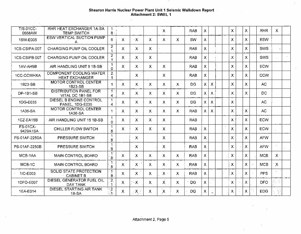
Shearon Harris Nuclear Power Plant Unit I Seismic Walkdown ReportAttachment 2: SWEL 1
TIS-01CC- RHR HEAT EXCHANGER 1A-SA 1 X RAB X X X RHR X0658AW TEMP.SWITCH 8 R
1SW-E005 ESW VERTICAL SUCTION PUMP 6 X x X X X SW X X X ESWA
1CS-CSIPA:007 CHARGING PUMP OIL COOLER 1 X X X RAB X X X SWS
1CS-CSIPB:007 CHARGING PUMP OIL COOLER 2 X X X RAB X X X SWS1
1AV-AH9B AIR HANDLING UNIT 9 1B-SB X X X X RAB X X X ECW0
1CC-CCWHXA COMPONENT COOLING WATER 2. X X RAB X X X CCWHEAT EXCHANGER 1
1B23-SB MOTORCONTROLCENTER 1 X X X X X DG X X X X AC1B23-SB
DISTRIBUTION PANEL FOR 1DP-IBI-SB VITAL DC 1B1-SB 4 X X X X X DG X X X X DCDIESEL B ENGINE CONTROL 1
1DG-E035 PANEL 1DGIE 4 X X X X X DG X X X ACPANEL, 1 DG-E035 41A36-SA MOTOR CONTROL CENTER 1 X X x X X RAB X X X X AC
1A36-SA
1CZ-EA15B AIR HANDLING UNIT 15 1B-SB X X X X RAB X X ECW0FS-01CX- 19429A1 CHILLER FLOW SWITCH 8 x X X X RAB X X X ECW9429A1SA 8
1PS-01AF-2250A PRESSURE SWITCH 8 X X RAB X X X AFW
PS-01AF-2250B PRESSURE SWITCH 1 X X RAB X X X AFWMCB-IAA MAIN CONTROL BOARD 8 X X X X X RAB X X X MCB X8
MCB-1C MAIN CONTROL BOARD 1 X X X X X RAB X X X MCB X
ilC-E003 SOLID STATE PROTECTION '1 XCABINET B 8. X x x x x RAB X X X PPS
1DFO-E007 DIESEL GENERATOR FUELOIL 2 X X X X DG X X DFODAY TANK 1 .. . ........
lEA-E014 DIESEL STARTING AIR TANK 2- -xD X EDG1EEA X 1X X X X DG X _X X EDG1 B-SA
Attachment 2, Page 5

Shearon Harris Nuclear Power Plant Unit 1 Seismic Walkdown ReportAttachment 2: SWEL I
DIESEL GENERATOR FUEL OIL 2 X X x X X DG X X X DFO:DFO-E006 DAY TANK 1X X X DG X ... F
1EA-E016, AIR RECEIVER 1D-SB x2 X X DG X .x x EDG
1EA-E015 AIR RECEIVER 1C-SB 2 x X X .. DG x• x x EDG
1 EA-50 CHECK VALVE 0 X X X x DG X X X EDG NIEA-35 CHECK VALVE 0 X X X DG. X X X EDG N:EA-19 CHECK VALVE 0, X X X X DG X X X EDG N1 EA-4 CHECK VALVE 0 X X X X DG X X x _EDG N
Attachment 2, Page 6

Shearon Harris Nuclear Power Plant Unit 1 Seismic Walkdown Report
Attachment 3: Base List 2
8 pages
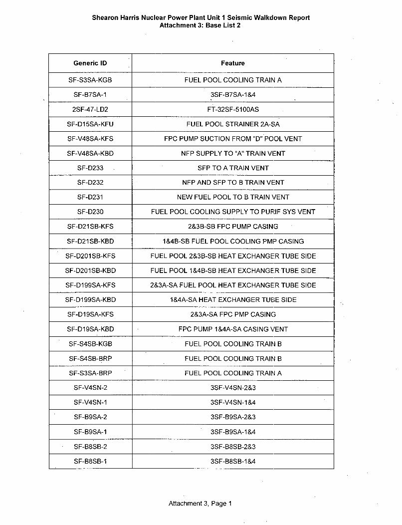
Shearon Harris Nuclear Power Plant Unit 1 Seismic Walkdown ReportAttachment 3: Base List 2
Generic ID Feature
SF-S3SA-KGB FUEL POOL COOLING TRAIN A
SF-B7SA-1 3SF-B7SA-1&4
2SF-47-LD2 FT-32SF-5100AS
SF-D15SA-KFU FUEL POOL STRAINER 2A-SA
SF-V48SA-KFS FPC PUMP SUCTION FROM "D" POOL VENT
SF-V48SA-KBD NFP SUPPLY TO "A" TRAIN VENT
SF-D233 SFP TO A TRAIN VENT
SF-D232 NFP AND SFP TO B TRAIN VENT
SF-D231 NEW FUEL POOL TO B TRAIN VENT
SF-D230 FUEL POOL COOLING SUPPLY TO PURIF SYS VENT
SF-D21SB-KFS 2&3B-SB FPC PUMP CASING
SF-D21SB-KBD 1&4B-SB FUEL POOL COOLING PMP CASING
SF-D201SB-KFS FUEL POOL 2&3B-SB HEAT EXCHANGER TUBE SIDE
SF-D201SB-KBD FUEL POOL 1&4B-SB HEAT EXCHANGER TUBE SIDE
SF-D199SA-KFS 2&3A-SA FUEL POOL HEAT EXCHANGER TUBE SIDE
SF-D199SA-KBD 1&4A-SA HEAT EXCHANGER TUBE SIDE
SF-D19SA-KFS 2&3A-SA FPC PMP CASING
SF-D19SA-KBD FPC PUMP 1 &4A-SA CASING VENT
SF-S4SB-KGB FUEL POOL COOLING TRAIN B
SF-S4SB-BRP FUEL POOL COOLING TRAIN B
SF-S3SA-BRP FUEL POOL COOLING TRAIN A
SF-V4SN-2 3SF-V4SN-2&3
SF-V4SN-1 3SF-V4SN-1 &4
SF-B9SA-2 3SF-B9SA-2&3
SF-B9SA-1 3SF-B9SA-1&4
SF-B8SB-2 3SF-B8SB-2&3
SF-B8SB-1 3SF-B8SB-1&4
Attachment 3, Page 1

Shearon Harris Nuclear Power Plant Unit I Seismic Walkdown ReportAttachment 3: Base List 2
SF-B7SA-2 3SF-B7SA-2&3
SF-B6SB-2 3SF-B6SB-2&3
SF-B6SB-1 3SF-B6SB-1&4
SF-B5SA-2. 3SF-B5SA-2&3
SF-B5SA-1 3SF-B5SA-I&4
SF-B4SB-2 3SF-B4SB-2&3
SF-B4SB-1 3SF-B4SB-i&4
SF-B30SB-2 3SF-B30SB-2&3
SF-B30SB-1 3SF-B30SB-1&4
SF-B3SA-2 3SF-B3SA-2&3
SF-B3SA-1 3SF-B3SA-1&4
SF-B29SA-2 3SF-B29SA-2&3
SF-B29SA-1 3SF-B29SA-1 &4
SF-B28SA-2 3SF-B28SA-2&3
SF-B28SA-1 3SF-B28SA-1 &4
SF-B26SA-2 3SF-B26SA-2&3
SF-B26SA-1 3SF-B26SA-1 &4
SF-B25SB-2 3SF-B25SB-2&3
SF-B25SB-1 3SF-B25SB-1 &4
SF-B24SB-2 3SF-B24SB-2&3
SF-B24SB-1 3SF-B24SB-1 &4
SF-B22SA-2 3SF-B22SA-2&3
SF-B22SA-1 3SF-B22SA-1 &4
SF-B21SB-2 3SF-B21SB-2&3
SF-B21SB-i 3SF-B21SB-1&4
SF-B20SA-2 3SF-B20SA-2&3
SF-B20SA-1 3SF-B20SA-1 &4
SF-B2SB-2 3SF-B2SB-2&3
SF-B2SB-1 3SF-B2SB-1 &4
Attachment 3, Page 2

Shearon Harris Nuclear Power Plant Unit I Seismic Walkdown ReportAttachment 3: Base List 2
SF-B1 9SA-2 3SF-B 19SA-2&3
SF-B1 9SA-1 3SF-B19SA-1&4
SF-B1 8SB-2 3SF-B18SB-2&3
SF-B18SB-1 3SF-B18SB-1&&4
SF-B 17SA-2 3SF-B17SA-2&3
SF-B1 7SA-1 3SF-B17SA-1&4
SF-B1 6SN-2 3SF-B16SN-2&3
SF-B1 6SN-1 3SF-B16SN-1&4
SF-B1 5SB-2 3SF-B15SB-2&3
SF-B15SB-1 3SF-B15SB-1&4
SF-B11SN-2 3SF-B11SN-2&3
SF-B11SN-1 3SF-B 11SN-1&4
SF-B1 0SB-2 3SF-B1OSB-2&3
SF-B130SB-1 3SF-B1OSB-1&4
SF-B1 SA-2 3SF-B 1SA-2&3
SF-B1SA-1 3SF-B1SA-1&4
1&4A33-SA-2C FUEL POOL COOLING PUMP 2&3A-SA
1&4B33-SB-4C FUEL POOL COOLING PUMP 2 & 3B-SB
1&4B33-SB-2D SPENT FUEL COOLING PUMP 1&4B-SB
1&4A33-SA-4D SPENT FUEL COOLING PUMP 1&4A-SA
FU1/2064 CONTROL FUSE MCC 1&4A33-SA-2C
1&4B33-SB-4C FUEL POOL COOLING PUMP 2&3B-SB
1&4B33-SB-39 FUEL POOL COOLING PUMP 2&3B-SB SPACE HEATER
1&4B33-SB-37 1&4B-SB PUMP MOTOR-HEATER
1&4B33-SB-2D SPENT FUEL POOL COOLING PUMP 1&4B-3B
1&4A33-SA-4D SPENT FUEL POOL COOLING PUMP 1&4A-SA
1&4A33-SA-39 2&3A-SA PUMP MOTOR HEATER
1 &4A33-SA-37 1&4A-SA PUMP MOTOR-HEATER
1&4A33-SA-2C SPENT FUEL POOL COOLING PUMP 2&3A-SA
Attachment 3, Page 3

Shearon Harris Nuclear Power Plant Unit I Seismic Walkdown ReportAttachment 3: Base List 2
FU1/2065. CONTROL FUSE MCC 1&4B33-SB-4C
1&4B-SB 1&4B-SB FUEL POOL COOLING PUMP
2&3B-SB 2&3B-SB FUEL POOL COOLING PUMP
2&3A-SA 2&3A-SA FUEL POOL COOLING PUMP
1&4A-SA 1&4A-SA FUEL POOL COOLING PUMP
2&3B-SB FUEL POOL COOLING PUMP 2&3B-SB MOTOR
2&3A-SA FUEL POOL COOLING PUMP 2&3A-SA MOTOR
1&4B-SB FUEL POOL COOLING PUMP 1&4B-SB MOTOR
1&4A-SA FUEL POOL COOLING PUMP 1&4A-SA MOTOR
FT-5100B-KGI FUEL POOL D INLET FLOW
PDS-5130B-2 FP COOLING PUMP 2&3B SUCTION STRAINER DP
PDS-5130B SF-S4SB STRAINER
PDS-5130A-2 FP COOLING PUMP 2&3A SUCTION STRAINER DP
PDS-5130A SF-S3SA STRAINER
PI-5130B-2 FP COOLING PUMP 2&3B DISCH PRESS
PI-5130B 1&4B-SB PUMP OUTLET
PI-5130A-2 FP COOLING PUMP 2&3A DISCH PRESS
PI-5130A 1&4A-SA PUMP OUTLET
TY/5110B2 SFP-1 TEMP CHANNEL B
TY/5110B1 SFP-1 TEMP CHANNEL B
TY/5110A2 SFP-1 TEMP CHANNEL A
TY/5110A1 SFP-1 TEMP CHANNEL A
TY/5100B2 NFP-1 TEMP CHANNEL B
TY/5100B1 NFP-1 TEMP CHANNEL B
TY/5100A2 NFP-1 TEMP CHANNEL A
TY/5100A1 NFP-1 TEMP CHANNEL A
TT-5110B-2 SFP C TEMP TRAIN B
TT-5110B SFP-1 TEMP TRAIN B
TT-5110A-2 SFP C TEMP TRAIN A
Attachment 3, Page 4

Shearon Harris Nuclear Power Plant Unit I Seismic Walkdown ReportAttachment 3: Base List 2
TT-5110A SFP-1 TEMP TRAIN A
TT-5100B-2 SFP D TEMP TRAIN B
TT-5100B NFP-1 TEMP TRAIN B
TT-510QA-2 SFP D TEMP TRAIN A-
TT-5100A NFP-1 TEMP TRAIN A
TD/5110A SFP-1 TEMP
TD/51 OQA NFP-1 TEMP
FT-5110B-KGI FUEL POOL C INLET FLOW
FT-5110B-KEH SFP-1 SUPPLY TRAIN B
FT-5110A-KGI FUEL POOL C INLET FLOW
FT-5110A-KEH SFP-1 SUPPLY TRAIN A
FT-510OB-KEH NFP-1 SUPPLY TRAIN B INLET FLOW UNIT 1&4
FT-5100A-KGI FUEL POOL D INLET FLOW
FT-5100A-KEH NFP-1 SUPPLY TRAIN A INLET FLOW UNIT 1&4
FI-5110B-2 FP COOLING PMP 2&3B-SB DISCHARGE FLOW INDICATOR
FI-5110B SFP COOLING PMP I&4B-SB DISCHARGE FLOW INDICATOR
FI-5110A-2 FP COOLING PUMP 2&3A-SA DISCHARGE FLOW INDICATOR
FI-5110A SFP COOLING PMP I&4A-SA DISCHARGE FLOW INDICATOR
TS-51 1 OB-2 SFP C TEMP HI
TS-5110B SPENT FUEL POOL TEMP HI
TS-51 1OA-2 SFP C TEMP HI
TS-511OA SPENT FUEL POOL TEMP HI
TS-51 00B-2 SFP D TEMP HI
TS-5100B NEW FUEL POOL TEMP HI
TS-51 OOA-2 SFP D TEMP HI
TS-5100A NEW FUEL POOL TEMP HI
TE-517OB-KGG 2&3B-SB HX OUTLET
TE-5170B-KEF I&4B-SB HX OUTLET
TE-5170A-KGG 2&3A-SA HX OUTLET
Attachment 3, Page 5

Shearon Harris Nuclear Power Plant Unit I Seismic Walkdown ReportAttachment 3: Base List 2
TE-5170A-KEF 1&4A-SA HX OUTLET
TE-5160B-KGG 2&3B-SB HX INLET
TE-5160B-KEF 1&4B-SB HX INLET
TE-5160A-KGG 2&3A-SA HX INLET
TE-5160A-KEF 1&4A-SA HX INLET
TE-5110B-KGG SPENT FUEL POOL C TEMP
TE-511OB-KEF SPENT FUEL POOL TEMP
TE-5110A-KGG SPENT FUEL POOL C TEMP
TE-51 1 OA-KEF SPENT FUEL POOL TEMP
TE-5100B-KGG SPENT FUEL POOL D TEMP
TE-5100B-KEF NEW FUEL POOL TEMP
TE-5100A-KGG SPENT FUEL POOL D TEMP
TE-5100A-KEF NEW FUEL POOL TEMP
FE-5110B-KGH SFP C 2 SUPPLY TRAIN B INLET FLOW UNIT 2&3
FE-51 10B-KEG SFP-1 SUPPLY TRAIN B INLET FLOW UNIT 1&4
FE-5110A-KGH SFP C SUPPLY TRAIN A INLET FLOW UNIT 2&3
FE-5110A-KEG SFP-1 SUPPLY TRAIN A INLET FLOW UNIT 1&4
FE-5100B-KGH SFP D SUPPLY TRAIN B INLET FLOW UNIT 2&3
FE-5100B-KEG NFP-1 SUPPLY TRAIN B INLET FLOW UNIT 1&4
FE-5100A-KGH SFP D SUPPLY TRAIN A INLET FLOW UNIT 2&3
FE-5100A-KEG NFP-1 SUPPLY TRAIN A INLET FLOW UNIT 1&4
PT-5140A 1&4A-SA PUMP OUTLET
LS-5100A1SA NEW FUEL POOL UNIT #1 HI LVL PART OF L S 5100ASA
CR4/2058 SPENT FUEL POOL D LEVEL ALARM
CR4/2056 SPENT FUEL POOL D WATER LEVEL ALARM
CR4/2054 SPENT FUEL POOL C WATER LEVEL ALARM
CR4/2052 SPENT FUEL POOL C WATER LEVEL ALARM INDICATION
CR2/904 FUEL POOL COOLING PUMP 1&4A-SA
CR2/2065 FUEL POOL COOLING PUMP 2&3B-SB STATUS
Attachment 3, Page 6
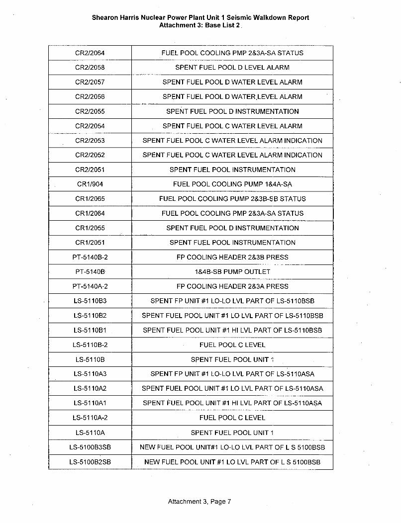
Shearon Harris Nuclear Power Plant Unit 1. Seismic Walkdown ReportAttachment 3: Base List 2
CR2/2064 FUEL POOL COOLING PMP 2&3A-SA STATUS
CR2/2058 SPENT FUEL POOL D LEVEL ALARM
CR2/2057 SPENT FUEL POOL D WATER LEVEL ALARM
CR2/2056 SPENT FUEL POOL D WATERLEVEL ALARM
CR2/2055 SPENT FUEL POOL D INSTRUMENTATION
CR2/2054 SPENT FUEL POOL C WATER LEVEL ALARM
CR2/2053 SPENT FUEL POOL C WATER LEVEL ALARM INDICATION
CR2/2052 SPENT FUEL POOL C WATER LEVEL ALARM INDICATION
CR2/2051 SPENT FUEL POOL INSTRUMENTATION
CR1/904 FUEL POOL COOLING PUMP 1&4A-SA
CR1/2065 FUEL POOL COOLING PUMP 2&3B-SB STATUS
CR1/2064 FUEL POOL COOLING PMP 2&3A-SA STATUS
CR1/2055 SPENT FUEL POOL D INSTRUMENTATION
CR1/2051 SPENT FUEL POOL INSTRUMENTATION
PT-5140B-2 FP COOLING HEADER 2&3B PRESS
PT-5140B 1&4B-SB PUMP OUTLET
PT-5140A-2 FP COOLING HEADER 2&3A PRESS
LS-51 110B3 SPENT FP UNIT #1 LO-LO LVL PART OF LS-51 1 OBSB
LS-51 110B2 SPENT FUEL POOL UNIT #1 LO LVL PART OF LS-51 1 OBSB
LS-51 101B1 SPENT FUEL POOL UNIT #1 HI LVL PART OF LS-51 1 OBSB
LS-5110B-2 FUEL POOL C LEVEL
LS-5110B SPENT FUEL POOL UNIT I
LS-51 1 0A3 SPENT FP UNIT #1 LO-LO LVL PART OF LS-51 1 OASA
LS-5110A2 SPENT FUEL POOL UNIT #1 LO LVL PART OF LS-511OASA
LS-5110A1 SPENT FUEL POOL UNIT #1 HI LVL PART OF LS-511OASA
LS-511OA-2 FUEL POOL C LEVEL
LS-51 10A SPENT FUEL POOL UNIT 1
LS-5100B3SB NEW FUEL POOL UNIT#1 LO-LO LVL PART OF L S 5100BSB
LS-5100B2SB NEW FUEL POOL UNIT #1 LO LVL PART OF L S 5100BSB
Attachment 3, Page 7
Shearon Harris Nuclear Power Plant Unit I Seismic Walkdown ReportAttachment 3: Base List 2
LS-5100B1SB NEW FUEL POOL UNIT #1 HI LVL PART OF L S 5100BSB
LS-5100B-2 FUEL POOL D LEVEL
LS-5100B NEW FUEL POOL UNIT 1
LS-5100A3SA NEW FUEL POOL UNIT#1 LO-LO LVL PART OF L S 5100ASA
LS-5100A2SA NEW FUEL POOL UNIT #1 LO LVL PART OF L S 5100ASA
LS-5100A-2 FUEL POOL D LEVEL
LS-5100A NEW FUEL POOL UNIT 1 HI LVL
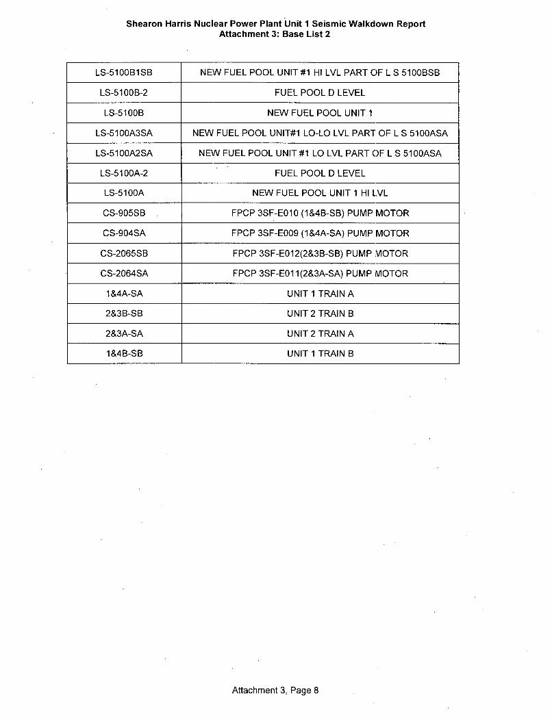
CS-905SB FPCP 3SF-EO10 (1&4B-SB) PUMP MOTOR
CS-904SA FPCP 3SF-E009 (1&4A-SA) PUMP MOTOR
CS-2065SB FPCP 3SF-EO12(2&3B-SB) PUMP MOTOR
CS-2064SA FPCP 3SF-EO1 1(2&3A-SA) PUMP MOTOR
I &4A-SA UNIT 1 TRAIN A
2&3B-SB UNIT 2 TRAIN B
2&3A-SA UNIT 2 TRAIN A
1&4B-SB UNIT 1 TRAIN B
Attachment 3, Page 8

Shearon Harris Nuclear Power Plant Unit 1 Seismic Walkdown Report
Attachment 4: Rapid Drain-Down List
1 page

Shearon Harris Nuclear Power Plant Unit I Seismic Walkdown ReportAttachment 4: Rapid Drain-Down List
Unique Equipment ID
TAG # Feature
lSF-146 UNIT 1 FUEL XFER CANAL EAST DRAIN ISOL
lSF-147 UNIT 1 FUEL XFER CANAL WEST DRAIN ISOL
2SF-146 UNIT 2 FUEL XFER CANAL EAST, DRAIN TO PURIFICATION SYSTEM
2SF-147 UNIT 2 FUEL XFER CANAL WEST, DRAIN TO PURIFICATION SYSTEM
Attachment 4, Page 1

Shearon Harris Nuclear Power Plant Unit I Seismic Walkdown Report
Attachment 5: SWEL 2
1 page

Shearon Harris Nuclear Power Plant Unit I Seismic Walkdown ReportAttachment 5: SWEL 2
Unique Equipment ID Feature Buildin, Rapid Drain Down
"SF E 00 FUEL POOL COOLING TRAIN A FHB
PT-41SF-5140AS 1&4A-SA PUMP OUTLET FIIB
2) •.010 . 1&4B-SB FUEL POOL COOLING ••FHB,PUMP
1SF-39 002 3SF-B7SA-1 &4 FHB
LS-n0 n5 ' 1 00A1 SA NEW FUEL POOL UNIT #1 HI LVL FHBLS-O1SF-510 "A1SA .... PART OF L S 5100ASA FHB
2SF-47-LD2 )FT-32SF-51IOOAS FH-B~
3SF-EO01 UNIT 1 TRAIN A FHB
FT-32SF-510OBS FUEL POOL D INLET FLOW FHB
lSF-146 UNIT 1 FUEL XFER CANAL EASTDRAIN ISOL
ISF-147 ," :' UNIT 1 FUEL XFER CANAL WESTlSF147 .. DRAIN ISOL
UNIT 2 FUEL XFER CANAL EAST,2SF-146 DRAIN TO PURIFICATION FHB X
SYSTEM
UNIT 2 FUEL XFER CANAL2SF-147 WEST, DRAIN TO PURIFICATION FHB X
SYSTEM
FU1/2065 CONTROL FUSE MCC 1&4B33- FHBSB-4C
1&4B33-SB-4C FUEL POOL COOLING PUMP FHB1&4B33-SB-4C2&3B-SBFH
Attachment 5, Page 1

Shearon Harris Nuclear Power Plant Unit I Seismic Walkdown ReportAttachment 8: Peer Review Report
Attachment 8: Peer Review Report
5 Pages

Shearon Harris Nuclear Power PlantSeismic Walkdown Peer Review Report
Peer Review activities were performed on the Seismic Walkdown Program in addition to theProgrammatic Controls / Oversight that were established for the project. A brief description ofthe Programmatic Controls / Oversight and Peer Review findings is provided below:
Programmatic Controls / Oversight
Programmatic Controls I Oversight were developed for the 2.3 Seismic Walkdowns andimplanted at Shearon Harris Nuclear Plant (HNP). A specification based on the EPRI guidancewas established to control SWEL development and walkdown requirements. A specificationwas developed since EPRI 1025286 was written as guidance, whereas, the specificationprovided more definitive criteria and control to avoid interpretation and promote consistency.The specification was inclusive of the EPRI guidance. A Quality Assurance (QA) person waspresent at the site during the inspection to assure form and specification compliance. Technicaloversight was performed by the Project Manager (PM). The PM was onsite during the SWELdevelopment and intermittently during the walkdowns and report generation phases of theproject. An in-process review of work was performed during those intervals. Inspections at thefour sites were being performed concurrently and lessons learned were relayed to theinspection teams at the other sites to determine if commonality was present within the fleet.These in-process reviews were performed through all phases of the project with the intent ofmeeting the intent of the EPRI guidance.
Peer Review
Separate from the programmatic controls implemented at the sites, Peer Review activities wereperformed on the seismic walkdown program that spanned from the development of thespecification and Seismic Walkdown Equipment List (SWEL) through the physical walkdownsand ultimately to the report preparation and review. The Peer Review team concluded that theinspection program was performed in accordance with the guidance provided in EPRI 1025286,Seismic Walkdown Guidance for Resolution of Fukushima Near-Term Task ForceRecommendation 2.3: Seismic, dated June, 2012. The Peer Review found the effort at HNP wasperformed in a competent manner and a very broad spectrum of components locatedthroughout the power block were included in the program. The results were documented intoDuke (Progress Legacy) EC 87910/URS Study 30703-061-13-05-100-003. Aspects of theprogram that were reviewed by the Peer Review justifying this statement are provided asfollows:
Attachment 8, page 1

.Inspection TeamThe Peer Review found Seismic Walkdown Engineers (SWE) performing the inspections werevery experienced with a background in design engineering including seismic design at nuclearfacilities dating back to design of the first generation nuclear power plants. SWEs had priorseismic walkdown experience at operating nuclear power plants, Department of Energyfacilities, and -other pertinent applications. Training consistent with the EPRI training wasprovided to all SWEs before any inspections were performed. The resumes of the SWEs werereviewed and it was determined that the SWEs were found to have qualifications that wereconsistent with the requirements of the regulatory guidance.
Selection of SWEL Items
The Peer Review concluded the process used to select SWEL items included -both selected anddiverse aspects. The list of equipment was obtained from the A-46 Safe Shutdown EquipmentList (SSEL) and the appropriate screening filters identified in the EPRI guidance were applied.The number of items included in the SWEL represented an appropriate number of items in eachequipment class when compared to the total number of items on the SSEL. The items thatwere individually selected typically were items that would have the most severe consequencein the event that the target item were to fail during the seismic event and resulted incomponents associated with the Emergency Diesel Generators, vital power, and heat removalsystems, etc. being well represented. Other conditions given additional consideration includedenvironmental and distribution into diverse structures, while items that are typically notincluded in programmatic inspections, (e.g. AOV, MOV, Appendix R, ASME Section Xl SubsectionIWE/IWL), were minimized. The process used to determine the SWEL items was determined tobe in accordance with the EPRI guidance and adequately represents a diverse sample of theequipment required to perform the five safety functions.
The Peer Review confirmed site Operations experience was included in the review of thecomponents to assure a representative distribution of equipment was included in the SWEL.Operations also performed preliminary walkdowns to determine if the components could besafely accessed. A selection/substitution criterion was established before the items wereassessed and if items were judged inaccessible, then the substitution criteria was used. ThePeer Review interviewed the personnel making the equipment selections and operationspersonnel to confirm an acceptable approach was used in selecting the equipment forsampling.
A sample of modifications performed at the site since the last IPEEE/A-46 inspection, previousIPEEE outliers, and upgrades were reflected in the SWEL.
The SWEL contained 100 components in SWEL-1 and an additional 14 items in SWEL-2 totaling114 selected items which was within the recommended range of 90-120 items. The SWEL wastaken from the IPEEE SSEL. The number of items inspected at the site is within the guidelinesprovided by EPRI.
Attachment 8, page 2

The process used to select the SWEL items, inclusion of Operations Personnel into the selection
of the items, IPEEE outliers and modifications were represented in the SWEL and the numberand distribution of items was in accordance with the EPRI guidance and confirmed by the PeerReview utilizing the Peer Review Checklist for the SWEL.
Pre-inspection Preparation
Peer Review was performed on the pre-inspection prepared walkdown packages whichconsisted of general configuration and structural drawings, anchorage detailing, and seismicdemand on the anchorage and it was confirmed that these packages were available in the fieldduring the inspection. The inspection packages were reviewed for thoroughness to the criteriaand samples were selected to determine appropriateness of the information. At randomintervals during the walkdown phase of the project, the SWEs were questioned to determine ifthey had been adequately prepared and specifically, they were questioned to determine if theyknew the vertical and horizontal strong motion demand in the areas that they would beworking. Additional instructions were provided during these intermediate assessments toaffect subsequent inspections. The SWEs demonstrated that they had adequately prepared forthe inspections prior to entering the field.
Conduct of Inspections
The Peer Review concluded the SWEs conducted field inspections with the walkdown packages"in-hand." The Seismic Walkdown Checklist (SWC) and Area Walk-By Checklist (AWC) werephysically used in the field and place keeping practices were employed. The SWEL items wereinspected; the forms were filled out in the field, and were reviewed by the SWEs before theyleft the area. As a result of conversations with the SWEs and Peer Review observations duringthe inspections, it was concluded that pertinent and thorough conversations occurred betweenthe SWEs in the field to generally reach a consensus on a real time basis in the field.
The inspections were performed in accordance with the EPRI guidance and within the confinesof the controlling specification.
Review of Walkdown and A rea Walk-By Checklist
The peer reviewers discussed the inspections with the SWEs prior to field implementation andsampled field reports during the inspections to determine adequacy of the inspection. TheSWEs were asked to describe the encountered field conditions and the forms were reviewed todetermine if the information was representative. The checklist was used predominately withhand written notes being used judiciously to reflect conditions. Intermediate guidanceresulting from the reviews during the inspection process was provided.
The final documents (i.e., package including checklist, photographs, drawings, notes) werecompared to the field notes with the QA representative reviewing 100% of the forms and thePeer Review reviewing over 30% of the forms. As a result of the Peer Review, there were someinstances that required the SWE to obtain and/or delineate additional information in the
Attachment 8, page 3

walkdown packages. Once incorporated, the information presented on the forms wasconsidered consistent with specification requirements and were judged representative of thefield conditions.
Decisions for Entering Potential Adverse Seisnic Conditions (PASCs) into CAP Process
The Peer Review concluded the identification of potential SSCs placed into the CAP process wasin accordance with the controlling walkdown specification. The specification decision processdelineated if items were to be initiated in CAP immediately or if they were to be evaluated inaccordance with the NTTF 2.3 Seismic program. Site documentation, (e.g. original A-46/IPEEEinspection results, existing CAP Non-Conforming Record (NCRs), calculations, evaluations, etc.),was reviewed if the SWEs could not make an immediate acceptance determination. If the itemwas originally evaluated and marked as Unknown for PASC determination on the walkdownchecklist and additional research did not yield a qualification of the existing condition, an NCRwould be initiated and the item identified as a PASC. If additional information was located andthe SWEs agreed on the status, the field notes were updated to reflect the acceptablecondition. This was represented on the final walkdown and/or walk-by checklists, and no NCRwould have been generated. The field notes were reviewed and evidence of documentingadditional information was observed. No PASCs were identified at Harris.
The Peer Review concluded that the process for evaluating identified issues in the field todetermine if they were PASCS was in accordance with the EPRI guidance. No PASCs wereidentified at Harris, therefore no Licensing Basis Reviews were performed.
Review of Licensing Basis
A Peer Review of the developed licensing basis evaluations, including the decision for enteringpotentially adverse seismic conditions into HNP's CAP, was performed and found to beacceptable.
Review of Submittal Report
The Peer Review reviewed the submittal report and it was found to be consistent with theinformation provided in the inspection reports and the supporting documentation and met theobjectives and requirements of the 50.54(f) letter.
SummarvThe Peer Review concluded the program was controlled and performed in accordance with theguidance outlined in EPRI 1025286, Seismic Walkdown Guidance for Resolution of FukushimaNear-Term Task Force Recommendation 2.3: Seismic. The number of items in the SWEL metand exceeded the minimum requirements and was distributed appropriately among the variouscriteria. The types of issues encountered were appropriate for the seismic demand for the site.Several significant modifications have been made at the site and these improvements wereincluded in the component sampling.
Attachment 8, page 4

The HNP site is a relatively later vintage nuclear site and it was the general impression of theSWEs that maintenance was being performed at the site and as a rule the site was conductingsite work in accordance with the Station's Housekeeping procedures.
In' conclusion, the Peer Review found the personnel involved in the inspections had sufficientknowledge of the site before the inspections and inspected the SWEL items in accordance with
provided guidance. The conditions encountered and the degree of severity of the conditionsindicates that HNP is conducting its maintenance and modification programs with considerationof seismic requirements.
The performed inspections and assessments were conducted in accordance with the guidanceprovided in EPRI 1025286, Seismic Walkdown Guidance for Resolution of Fukushima Near-TermTask Force Recommendation 2.3: Seismic. The results were assessed to be reasonable and
consistent and consistent with seismic demand for the region.
Attachment 8, page 5

ENCLOSURE 2REPORT REVIEW BY SITE MANAGEMENT
CAROLINA POWER & LIGHT COMPANY
SHEARON HARRIS NUCLEAR POWER PLANT, UNIT NO. IDOCKET NO. 50-400
RENEWED LICENSE NO. NPF-63
SHEARON HARRIS NUCLEAR POWER PLANT, UNIT NO.1 RESPONSE TORECOMMENDATION 2.3 SEISMIC WALKDOWN OF THE NEAR-TERM TASKFORCE REVIEW OF INSIGHTS FROM THE FUKUSHIMA DAI-ICHI ACCIDENT
1 Page

Report Review by Site Management
This submittal report is provided to the Nuclear Regulatory Commission in response toits request for information. Specifically, by letter dated March 12, 2012, the Staffrequested licensees to provide information regarding Recommendation 2.3 (Seismic) ofthe Near-Term Task Force Review of insights from the Fukushima Dai-Ichi Accident.The report provides information for the Shearon Harris Nuclear Power Plant, Unit No. 1regarding the performance of seismic walkdowns to identify and address degraded,non-conforming or unanalyzed conditions and to verify the current plant configurationwith the current seismic licensing basis. The information provided herein and theactivities described in this report are consistent with the guidance provided by theElectric Power Research Institute's (EPRI) 2012 Technical Report 1025286 titled"Seismic Walkdown Guidance For Resolution of Fukushima Near-Term Task ForceRecommendation 2.3: Seismic."
The signatures below document site management review of this document:
Signatures Date
Harris Fukushima Seismic Lead
Harris Seismic Engineer
Harris Design Engineering Supervisor
Prb- C12f-l I
Additionally, the Walkdown Report is submitted under covermanagement.
letter signed by senior site