securing theconstrained application...
TRANSCRIPT

R E S E A R C H G R O U P F O R
Distributed Systems
Master’s Thesisat the Institute for Pervasive Computing, Department of Computer Science, ETH Zurich
Securing theConstrained Application Protocol
by Stefan Jucker
Autumn 2012
ETH student ID: 06-912-414E-mail address: [email protected]
Supervisors: Dipl.-Ing. Matthias KovatschProf. Dr. Friedemann Mattern
Date of submission: 10 October 2012


Declaration of Originality
I hereby declare that this written work I have submitted is original work which I alonehave authored and which is written in my own words.With the signature I declare that I have been informed regarding normal academic citationrules and that I have read and understood the information on ’Citation etiquette:’
http://www.ethz.ch/students/exams/plagiarism_s_en.pdf
The citation conventions usual to the discipline in question here have been respected.This written work may be tested electronically for plagiarism.
Zurich, 10 October 2012
Stefan Jucker
iii


Acknowledgments
I would like to thank Matthias Kovatsch for the support and guidance during the processof writing this master’s thesis. My gratitude also goes to my interoperability test partners,particularly Daniele Trabalza with whom I have spent many exhausting hours of debugging,fixing and testing of our implementations.
Finally, I would like to thank my family and my friends, especially Ueli Ehrbar, fortheir support throughout my studies and the master’s thesis.
v


Abstract
Although the security needs for the Internet of Things are well-recognised, it is still notfully clear how existing IP-based security protocols can be applied to this new environmentwith constrained nodes and low-power, lossy networks. This thesis provides a state-of-the-art survey and a roadmap specifying the necessary steps to realise the security suite fordifferent Constrained Application Protocol (CoAP) implementations of the DistributedSystems Group. As a first step, we implemented Datagram Transport Layer Security(DTLS) for Californium (Cf), a CoAP framework written in Java for unconstrainedenvironments. This implementation provides all the specified mandatory functionality andhas been tested for interoperability with three other DTLS implementations. Analysed inan unconstrained environment, a full handshake increases the round-trip time by at least130ms compared to an unsecured CoAP request, which takes about 40ms. Based on theperformance and profiling analysis, and the gained experience during the implementationphase, we present an outlook on the future work that needs to be undertaken towards aconstrained environment.
vii


Contents
Abstract vii
Glossary xi
Objectives xiii
1 Introduction 11.1 Motivation . . . . . . . . . . . . . . . . . . . . . . . . . . . . . . . . . . 11.2 Contribution . . . . . . . . . . . . . . . . . . . . . . . . . . . . . . . . . 21.3 Outline . . . . . . . . . . . . . . . . . . . . . . . . . . . . . . . . . . . 2
2 The Constrained Application Protocol 32.1 Overview . . . . . . . . . . . . . . . . . . . . . . . . . . . . . . . . . . 32.2 CoAP Implementations . . . . . . . . . . . . . . . . . . . . . . . . . . . 4
3 Security Survey 73.1 Security Considerations . . . . . . . . . . . . . . . . . . . . . . . . . . . 73.2 Manufacturing Security . . . . . . . . . . . . . . . . . . . . . . . . . . . 103.3 Security Bootstrapping . . . . . . . . . . . . . . . . . . . . . . . . . . . 113.4 Operational Security . . . . . . . . . . . . . . . . . . . . . . . . . . . . 123.5 Roadmap . . . . . . . . . . . . . . . . . . . . . . . . . . . . . . . . . . 15
4 DTLS for Californium 234.1 Overview . . . . . . . . . . . . . . . . . . . . . . . . . . . . . . . . . . 234.2 DTLS Layer . . . . . . . . . . . . . . . . . . . . . . . . . . . . . . . . . 244.3 Handshaker . . . . . . . . . . . . . . . . . . . . . . . . . . . . . . . . . 264.4 DTLS Session . . . . . . . . . . . . . . . . . . . . . . . . . . . . . . . . 274.5 Record . . . . . . . . . . . . . . . . . . . . . . . . . . . . . . . . . . . . 274.6 DTLS Message . . . . . . . . . . . . . . . . . . . . . . . . . . . . . . . 284.7 DTLS Flight . . . . . . . . . . . . . . . . . . . . . . . . . . . . . . . . . 29
5 Implementation 315.1 DTLSLayer . . . . . . . . . . . . . . . . . . . . . . . . . . . . . . . . . 315.2 Cryptography . . . . . . . . . . . . . . . . . . . . . . . . . . . . . . . . 325.3 Ciphersuites . . . . . . . . . . . . . . . . . . . . . . . . . . . . . . . . . 355.4 Certificates . . . . . . . . . . . . . . . . . . . . . . . . . . . . . . . . . 37
ix

Contents
5.5 Error Handling . . . . . . . . . . . . . . . . . . . . . . . . . . . . . . . 385.6 Serialisation . . . . . . . . . . . . . . . . . . . . . . . . . . . . . . . . . 395.7 Fragmentation . . . . . . . . . . . . . . . . . . . . . . . . . . . . . . . . 435.8 Properties . . . . . . . . . . . . . . . . . . . . . . . . . . . . . . . . . . 445.9 Providing Reliability . . . . . . . . . . . . . . . . . . . . . . . . . . . . 46
6 Analysis 516.1 Testing . . . . . . . . . . . . . . . . . . . . . . . . . . . . . . . . . . . . 516.2 Performance . . . . . . . . . . . . . . . . . . . . . . . . . . . . . . . . . 536.3 Profiling . . . . . . . . . . . . . . . . . . . . . . . . . . . . . . . . . . . 56
7 Discussion 617.1 Threat Model . . . . . . . . . . . . . . . . . . . . . . . . . . . . . . . . 617.2 Performance Optimisation . . . . . . . . . . . . . . . . . . . . . . . . . 637.3 Known Issues . . . . . . . . . . . . . . . . . . . . . . . . . . . . . . . . 647.4 Implementation Notes . . . . . . . . . . . . . . . . . . . . . . . . . . . . 667.5 Optimising the Current DTLS Implementation . . . . . . . . . . . . . . . 687.6 Future Implementations . . . . . . . . . . . . . . . . . . . . . . . . . . . 69
8 Conclusion 71
Bibliography 73
A Handshake Protocol 77A.1 Full Handshake . . . . . . . . . . . . . . . . . . . . . . . . . . . . . . . 77A.2 Abbreviated Handshake . . . . . . . . . . . . . . . . . . . . . . . . . . . 82
B Elliptic Curve Cryptography 83B.1 ECC-Based Key Exchange Algorithms . . . . . . . . . . . . . . . . . . . 83B.2 Key Agreement Scheme . . . . . . . . . . . . . . . . . . . . . . . . . . 83B.3 Signature Scheme . . . . . . . . . . . . . . . . . . . . . . . . . . . . . . 84B.4 Advantages . . . . . . . . . . . . . . . . . . . . . . . . . . . . . . . . . 84
C Keytool and OpenSSL 85
x

Glossary
AEAD Authenticated Encryption with Associated Data
AES Advanced Encryption Standard
CA Certificate Authority
CCM Counter with CBC-MAC
Cf Californium
CoAP Constrained Application Protocol
CoRE Constrained RESTful Environments
CPU Central Processing Unit
CSR Certificate Signing Request
Cu Copper
DANE DNS-based Authentication of Named Entities
DER Distinguished Encoding Rules
DoS Denial-of-Service
DSA Digital Signature Algorithm
DTLS Datagram Transport Layer Security
ECC Elliptic Curve Cryptography
ECDH Elliptic Curve Diffie-Hellman
ECDSA Elliptic Curve Digital Signature Algorithm
Er Erbium
ESP Encapsulating Security Payload
xi

Glossary
HMAC Hash-Based Message Authentication Code
IANA Internet Assigned Numbers Authority
IETF Internet Engineering Task Force
IoT Internet of Things
IP Internet Protocol
IPsec Internet Protocol Security
JAR Java Archive
JCA Java Cryptography Architecture
JDK Java Development Kit
JVM Java Virtual Machine
MAC Message Authentication Code
MCU Microcontroller Unit
MTU Maximum Transmission Unit
PFS Perfect Forward Secrecy
PRF Pseudorandom Function
PSK Pre-Shared Key
SECG Standards for Efficient Cryptography Group
SICS Swedish Institute of Computer Science
TLS Transport Layer Security
TLV Type-Length-Value
UDP User Datagram Protocol
xii

Objectives
The student will assess the drafts in the Constrained RESTful Environments (CoRE)working group as well as available implementations of the underlying security mechanismsand discuss possible threats to the protocol and its limitations. Based on these results,a roadmap will be created listing the steps that need to be taken to realise the securitysuite for the CoAP implementations of the Distributed Systems Group: Californium(Cf), Erbium (Er), and Copper (Cu). The theoretical results will be applied to Cf byimplementing all mandatory security options of the latest CoAP Internet-Draft. In a finalstep, the student shall evaluate the realised security suite qualitatively through threatmodelling and quantitatively through performance measurements.
xiii


1 Introduction
1.1 Motivation
The Internet Engineering Task Force (IETF) is currently standardising the ConstrainedApplication Protocol (CoAP) [37] and with this the need for standardised security followsnaturally. In the Internet, the de facto standard to achieve security is Transport LayerSecurity (TLS) paired with a public-key infrastructure. However, this protocol is notsuited for constrained networks due to its need for reliable messaging and also its highdemand on the hardware. Therefore, multiple alternatives have been proposed to solve thesecurity requirements for constrained environments.
The CoAP specification suggests either the use of Datagram Transport Layer Security(DTLS) or Internet Protocol Security (IPsec) to achieve data origin authentication, integrityand replay protection, and encryption for CoAP messages [37]. Additionally, otherprotocols and modifications of the mentioned approaches exist which are undergoingreview by the IETF and Constrained RESTful Environments (CoRE) working groups. Sofar, however, no standard for end-to-end security could be established. This is especiallydifficult due to the discrepancy between the demand for high security standards and theavailable envisioned inexpensive but constrained hardware.
Before network security can be applied, the small devices, mostly without any userinterface, must be commissioned into the network. This security bootstrapping poses alsoa challenge that needs to be solved for an effective use of CoAP . The same is true forthe physical vulnerabilities of devices: They could easily be stolen or forcibly altered tocompromise security.
1

1 Introduction
1.2 Contribution
By the start of this master’s thesis, no implementation existed that fully conformed tothe DTLS specification. This thesis presents a DTLS implementation, integrated intothe CoAP framework Californium (Cf) , that conforms to all mandatory requirementsdefined in the DTLS [33] and CoAP [37] specifications. Furthermore, it gives an in-depthanalysis of the different security approaches and presents ideas for optimising securityspecifications and the current implementation to be more friendly towards constrainedenvironments.
1.3 Outline
After introducing the Constrained Application Protocol (CoAP) , the thesis provides a state-of-the-art survey in Chapter 3 about the current security measures and outlines a roadmapspecifying the necessary steps to achieve a secure CoAP implementation. Chapters 4and 5 document the implementation for CoAP over DTLS deployed in an unconstrainedenvironment. The following Chapter 6 analyses the implementation according to itssecurity and performance. The remaining chapters will present the achieved results,discuss them and draw the conclusion.
2

2 The Constrained ApplicationProtocol
2.1 Overview
The Constrained Application Protocol (CoAP) is a specialised Web transfer protocolfor use with constrained nodes (e.g., low-power sensors, switches, or valves) and con-strained (e.g., low-power, lossy) networks. The Constrained RESTful Environments(CoRE) working group aims at realising the REST architecture in a suitable form for themost constrained nodes and networks [37]. One design goal of CoAP has been to keepmessage overhead small, thus limiting the use of fragmentation and sparing constrainednetworks, like 6LoWPAN, to execute expensive fragmentation of IPv6 packets. CoAPis an application layer protocol that easily translates to HTTP for integration with theexisting Web while meeting specialised requirements such as multicast support, very lowoverhead and simplicity for constrained environments, and machine-to-machine applica-tions (e.g., [8], [23]). It makes use of two message types, requests and responses, using asimple binary fixed-size header format which is potentially followed by options in Type-Length-Value (TLV) format and a payload. The length of the payload is determined bythe datagram length and when bound to the User Datagram Protocol (UDP) (the standardcase), it must fit within a single datagram.
CoAP has the following main features [37]:
• Constrained Web protocol fulfilling machine-to-machine requirements.• UDP binding with optional reliability supporting unicast and multicast requests.• Low header overhead and parsing complexity.• Push notifications through a publish/subscribe mechanism.• Simple proxy and caching capabilities.• Security binding to Datagram Transport Layer Security (DTLS) .
One of CoAP ’s most promising applications will be the Internet of Things (IoT) : Atthe beginning of the IoT , everyday objects were interconnected through their virtualrepresentation using barcodes and later RFID. Now, the IP-based IoT becomes reality withtiny embedded devices that are directly connected to the Internet over IP [24], enabled byCoAP which completes the IP stack (in combination with 6LoWPAN [19] and RPL [43])for such constrained devices.
3

2 The Constrained Application Protocol
2.2 CoAP Implementations
Currently, there exist three implementations of CoAP developed at the Institute forPervasive Computing, ETH Zurich: Californium (Cf) , Erbium (Er) , and Copper (Cu) .
2.2.1 Californium
Cf 1 is a CoAP framework written in Java and developed for the use in unconstrainedenvironments. Cf is based on a layered architecture, extending the two-layer approachdescribed in the CoAP draft [37]. This allows an isolated implementation of differentaspects such as message retransmission, transactions, block-wise transfer and of coursesecurity as we will discuss later in detail. The architectural design of Cf is documented inthe lab report [29] of the initial implementation. Please note that due to the continuousadvancement of Cf , some described design decisions in the lab report are already outdated.
2.2.2 Erbium
Er is a low-power REST Engine for the Contiki operating system2 which allows tiny,battery-operated, low-power systems to communicate with the Internet [21]. Therefore,this implementation is specialised for constrained environments as it is designed to run onsmall amounts of memory and low-power Central Processing Units (CPUs) or Microcon-troller Units (MCUs) .
2.2.3 Copper
Cu3 is a CoAP user-agent for Firefox implemented in JavaScript. It enables users tobrowse IoT devices in the same fashion they are used to explore the Web. This is done byproviding a presentation layer that is originally missing in the CoAP protocol suite. Sinceit is embedded into Firefox as an add-on, it is designed for unconstrained environmentsas Cf . Its ability to render a number of different content types such as JSON or theCoRE Link Format makes it a useful testing tool for application as well as protocoldevelopment [24].
1https://github.com/mkovatsc/Californium2http://www.contiki-os.org/3https://github.com/mkovatsc/Copper
4

2.2 CoAP Implementations
2.2.4 Others
Lerche, Hartke and Kovatsch list in their CoAP survey additional CoAP implementations[24]:
jCoAPjCoAP4 is a Java implementation for unconstrained devices and embedded systemssuch as Java-based smartphones and mobile devices (e.g., Android). It provides aCoAP -to-HTTP and HTTP-to-CoAP proxy which performs protocol translationsbetween the two protocols.
libcoaplibcoap5 is a library for CoAP message parsing, serialisation, and transmission.It has been ported to different embedded system architectures, in particular theoperating systems Contiki and TinyOS6.
4http://code.google.com/p/jcoap/5http://libcoap.sourceforge.net/6http://www.tinyos.net/
5


3 Security Survey
3.1 Security Considerations
This section gives an overview about the security threats and vulnerabilities in the IoTand should sharpen the focus on what must be considered when trying to secure CoAP .Garcia-Morchon, et al. identify nine potential security threats, which are summarised inTable 3.1 ordered by the vulnerable layer and the lifetime phase of a thing [13].
ManufacturingInstallation,Commissioning Operation
PhysicalThing
Device Cloning Substitution Privacy ThreatExtraction of Params
ApplicationLayer
Firmware Replacement
TransportLayer
EavesdroppingMan-in-the-Middle
EavesdroppingMan-in-the-Middle
NetworkLayer
EavesdroppingMan-in-the-Middle
DoSRouting Attack
PhysicalLayer
DoS
Table 3.1: The security threat analysis. The potential attacks are grouped by the lifetimephase and the potential point of vulnerability.
Roughly, the security threats can be divided into two categories: physical (local) attacksand non-physical (remote) attacks. Physical attacks are executed by attackers whichforce their way into the physically unprotected thing and try to compromise it in differentways [5, 13].
7

3 Security Survey
Cloning of ThingsAn untrusted manufacturer can easily clone the physical characteristics, firmwareand software, or security configurations during the manufacturing process of a thing.The manufacturer could sell the cloned thing at a cheaper price in the market to gainfinancial benefits or even worse implement additional functionality which couldlater be used with malicious intent.
Malicious Substitution of ThingsDuring the installation of a thing, a genuine thing may be replaced with a low-quality variant without being detected. The main motivation may be cost savings bysignificantly reducing the installation and operational costs.
Firmware Replacement AttackAfter a certain time into the operational phase, the software or firmware of athing may be updated to introduce new functionality or new features. During thismaintenance phase, an attacker may be able to exploit such an upgrade by replacingit with malicious software. If such an attack is successful, the operational behaviourof this thing can be influenced and exploited afterwards.
Extraction of Security ParametersThings deployed in ambient environments are normally physically unprotected andcan easily be captured by an attacker. When in possession of a thing, the attackermay try to extract certain security information such as keys from this thing. Once akey is compromised (e.g., a group key), the whole network may be compromised aswell.
Denial-of-Service AttackA Denial-of-Service (DoS) attack can be launched by physically jamming thecommunication channel.
All of the described attacks depend on a physically present attacker. Therefore, thesecurity measures that need to be taken to protect things against such attacks go beyond thescope of Internet protocol security. As we focus on securing CoAP , the countermeasuresagainst these attacks will only be discussed in combination with Internet protocol security.
The non-physical (remote) attacks include the following [3, 13, 28]:
Eavesdropping AttackDuring commissioning of a thing into a network, it can be vulnerable to eaves-dropping: If security parameters or keying material are exchanged in the clear, theattacker might be able to retrieve the secret keys established between the communi-cating entities. But even a protected network can be vulnerable to eavesdropping,e.g., in the event of session key compromise which can happen after a longer periodof using the same key without renewing it.
8

3.1 Security Considerations
Man-in-the-Middle AttackA man-in-the-middle attack is possible during the commissioning phase, e.g., whenkeying material is exchanged in the clear and the security of the key agreementalgorithm depends on the assumption that no third party is able to eavesdrop onor sit in between the two communicating entities. During the operational phase,man-in-the-middle attacks are only possible when anonymous connections are used.
Routing AttackRouting attacks include amongst others a) Sinkhole attack, where the attackerdeclares himself to have a high-quality route, allowing him to do anything to allpackets passing through. b) Selective forwarding, where the attacker may drop orforward packets selectively.
Denial-of-Service AttackAn attacker can continuously send requests to be processed by specific things andtherefore exhaust their resources. This is especially dangerous in the IoT sincethings usually have tight memory and limited computation capabilities.
Privacy ThreatThe tracking of the location and the usage of a thing may pose a privacy risk toits users. An attacker could deduce behavioural patterns of the user by inferringinformation based on the gathered data.
As we have identified potential security threats, let us define what we want to achievewhen we talk about security requirements against these threats [14, 28, 41]:
ConfidentialityConfidentiality describes the prevention of disclosure of information to unauthorisedentities. We want to achieve confidentiality to prohibit privacy threat and eaves-dropping attacks. Please note that an attacker can observe communication patternsof a user even if confidentiality is provided by the connection, allowing him to inferprivate information about the user anyway. This attack is just complicated whenconfidentiality is provided, but not fully averted.
AuthenticityAuthenticity guarantees that all parties involved in the communication are who theyclaim they are.
IntegrityIntegrity is violated if a message can actively be altered during transmission withoutbeing detected. If message integrity and authenticity is guaranteed, man-in-the-middle attacks can be averted.
Non-RepudiationNon-repudiation implies that one party of a transaction cannot deny having receiveda transaction nor can the other party deny having sent a transaction.
9

3 Security Survey
AvailabilityEnsuring the survivability of services to parties when needed, even during a DoSattack.
AuthorisationAuthorisation is the function of specifying access rights to resources.
Data FreshnessThis can mean data freshness as well as key freshness. It ensures that no adversarycan replay old messages.
These security services can be implemented by a combination of cryptographic mecha-nisms such as block ciphers, hash functions, or signature algorithms and non-cryptographicmechanisms, which implement authorisation and other security policy enforcement as-pects.
So far, the listed security threats and goals can be applied to arbitrary networks. We,however, are focusing on constrained networks, therefore we need to look at the additionalconsequences that arise in constrained environments. One additional problem is the smallpacket size, which may result in fragmentation of larger packets in security protocols (e.g.,a large key exchange message). This may open new attack vectors for state exhaustionDoS attacks [13]. Further, the size and number of messages should be minimised to reducememory requirements and optimise bandwidth usage, while maintaining high securitystandards. When reducing or simplifying a security protocol in order to minimise energyconsumption, one must also expect losses in the security quality [30]. An appropriatetrade-off must be found for each individual environment. Another problem is the stillexisting gap between Internet protocols and the IoT , namely 6LoWPAN and CoAP , due toperformance reasons. These differences can easily be bridged using protocol translators atgateways, but it becomes a major obstacle once end-to-end security measures betweenIoT devices and Internet hosts are used. When a message is protected using messageauthentication codes or encryption or both, the protected parts of the message becomeimmutable. Thus, making rewriting not possible for the translators [13].
As can be seen in Table 3.1, there are roughly three different phases in the lifetimeof each individual thing, each phase exposed to different threats and having particularsecurity requirements. We will go through these three phases and describe the threats andavailable techniques to protect a thing against those.
3.2 Manufacturing Security
The life of a thing starts when it is manufactured. There are several difficulties duringthis phase: a) Normally, there is no single manufacturer that creates all nodes whichmust interact with each other. Therefore, interoperability and trust bootstrapping between
10

3.3 Security Bootstrapping
nodes of different vendors is important. b) An untrusted manufacturer can easily clonethe physical characteristics, firmware, or security configuration of a thing and sell itfor a cheaper price, or harm the original manufacturer’s reputation due to lower qualitystandards. c) A manufacturer can implement additional functionality within the clonedthing, such as a backdoor [13].
To solve these security problems, no classic cryptographic mechanism can be used.Rather, legal methods must be applied, like having contracts with the manufacturerregulating these issues. Of course, this technique does not result in tight security, butduring this phase total security cannot be achieved. One needs to hope that trust can beestablished on pain of penalties.
3.3 Security Bootstrapping
As can be seen in Table 3.1, there are several security threats during the commissioningphase. In this phase, a device is first installed and then provided with an identity, secretkeys, and a list of identities of nodes it can communicate with during normal operation.Thus, it is crucial that the commissioning phase is not compromised, e.g., an attacker couldeavesdrop on a unsecured connection and extract operational keying material. That is whywe need security bootstrapping before the network can operate normally. Bootstrapping iscomplete when settings have been securely transferred prior to normal operation in thenetwork.
Sarikaya, et al. describe a framework for initially configuring smart objects securely [35].They name two distinct phases during the bootstrapping process: the provisioning andbootstrapping phase. In the provisioning phase, the thing is provisioned with staticallyconfigured parameters like certificates (potentially, this has already been done during themanufacturing phase), which are needed in the bootstrapping phase. Using this staticallyconfigured information, the dynamically configured information is set up. Further, theydefine two distinct channels through which two nodes can communicate: the controland data channel. The control channel is used during the bootstrapping phase and thedata channel during normal network operation. When the control and data channel areidentical, the bootstrapping is done In-Band, otherwise Out-of-Band. Depending onwhether the control channel is secured or not, different bootstrap security methods canbe chosen. Typically, some high-security method should be used to generate a sharedsecret, which is then used to secure the actual bootstrapping channel using symmetricencryption. The authors propose several methods and note that the negotiated techniqueshould take advantage of the available hardware resource (such as hardware encryptionaccelerators) [36]:
11

3 Security Survey
NoneNo encryption or authentication is provided, the messages are exchanged in clear-text. It is assumed that some other layer provides security.
Asymmetric with User Authentication, Followed by SymmetricA shared secret is generated using a Diffie-Hellman style key exchange. Theauthentication will be provided by the user, by confirming cryptographic signaturesbetween two devices. With the shared secret, some symmetric encryption is used tosecure the actual bootstrapping channel.
Asymmetric with Certificate Authority, Followed by SymmetricSimilar as the previous method, but instead of required user interaction, a certificateauthority provides authenticity.
Cryptographically Generated Address Based Address Ownership VerificationThis method includes binding a public signature key to an IPv6 address which canthen be used to verify the address ownership. Messages sent from this IPv6 addresscan be protected by attaching the said public key and signing the message with thecorresponding private key. The advantage about this approach is that the protectionworks without a Certificate Authority (CA) or any security infrastructure [4].
3.4 Operational Security
The operational phase starts after the bootstrapping phase is completed. In this phase,CoAP is the main transfer protocol used for communication between things. The CoAPspecification defines two ways to provide security and authentication during the operationalphase: DTLS and IPsec. They differ both at their application as well as their resultingsecurity.
3.4.1 Internet Protocol Security
The IPsec Encapsulating Security Payload (ESP) is a protocol for securing InternetProtocol (IP) communications by encrypting and authenticating each IP packet [20].Unlike DTLS , it operates at the network layer of the Internet protocol suite and therefore itis transparent to the application layer and does not require any considerations for a CoAPimplementation. This fact has its upside as well as its downside: It provides confidentialityand data-origin authentication at the price of approximately 10 bytes per packet [37]without requiring the CoAP implementation to be altered, but it may be not appropriatefor many environments due to unavailable support in the IP stack or missing access toconfigure it.
12

3.4 Operational Security
3.4.2 DTLS
DTLS is a protocol for securing network traffic which has been specified by the IETFin RFC 6347 [33]. Unlike its role model TLS , it does not depend on reliable messagetransfer and can therefore be used with unreliable datagram transport, e.g., UDP . It isdesigned to be as close to TLS as possible, so it is defined as a series of deltas to TLS .The main changes to the protocol due to lossy message transfer (when using UDP ) are:a) Handling packet loss, b) reordering of messages, and c) message sizes. The concretehandling of these challenges are described in Chapter 5.
DTLS is a protocol composed of two layers: The lower layer is called the DTLSRecord Protocol, which provides connection security that has two basic properties: a) Theconnection is private by using symmetric encryption. b) The connection is reliable byincluding a message integrity check. These options may be used alone, together or not atall. The protocol encapsulates four higher-level protocols [10]:
DTLS Handshake ProtocolThis protocol is used to negotiate the security parameters of a session later used forprotected communication.
DTLS Change Cipher Spec ProtocolThe change cipher spec protocol exists to signal transitions in ciphering strategies. Itis used to notify the receiving party that subsequent records will be protected usingthe negotiated security parameters.
DTLS Alert ProtocolThis protocol can be used at any time during the handshake and up to the closure ofa session, signalling either fatal errors or warnings.
DTLS Application Data ProtocolApplication data messages are carried by the record layer and are fragmented,compressed, and encrypted based on the current connection state.
While DTLS has been defined in the CoAP draft to be mandatory [20], it is not fullyoptimal for resource-constrained networks as it (or more accurate TLS ) was designed fortraditional computer networks. For example, large buffers are needed to handle messageloss by retransmitting the last flight of the handshake protocol or to store all the fragmentswhen fragmentation must be applied due to smaller Maximum Transmission Unit (MTU) .Another problem is the use of X.509 certificates to achieve mutual authentication betweenthe peers: such a certificate chain can easily grow to the size of a few kilobytes whichleads to high fragmentation in networks with a small MTU resulting in a higher chance ofmessage lost and need to retransmit the whole flight. To address this issue, the concept ofraw public key certificates has been drafted in [44] and declared mandatory in the DTLSspecification: By sending only the peer’s public key and validate that public key using anout-of-band technique, a large part of the X.509 certificate chain could be cut and need
13

3 Security Survey
not to be sent over the resource-constrained network. A detailed description about thisconcept can be found in Section 5.4.
There are still great challenges to overcome, if DTLS should become a valuabletechnique for securing a constrained environment in the future: The protocol needs tobe simplified, stripped off all unnecessary features to achieve a useful trade-off betweensecurity and a light-weight implementation suitable for a constrained environment.
3.4.3 Link-Layer Security
As we have seen security protocols applied at the network and transport layer, let uslook at security at the link layer. The current IoT uses for communication primarily6LoWPAN [26] which builds on the IEEE 802.15.4 link-layer. 802.15.4 link-layer securityis the current state-of-the-art security solution for the IP-connected IoT [31]. It providesdata encryption and integrity verification, which is achieved by a single pre-shared keyused for symmetric cryptography applied to all outgoing packets while message integrity isrealised by including a Message Authentication Code (MAC) in the packets. Its advantagesare network protocol independence and hardware support for the cryptographic functionsby 802.15.4 radio chips. Unfortunately, there is one big drawback with this securityapproach: The link-layer security only provides hop-by-hop security which implies thateach node in the communication path must be trusted and host authentication is notpossible. Additionally, messages leaving the 802.15.4 network will not be protectedanymore by link-layer security mechanisms. Since end-to-end security cannot be achievedby using solely this approach, additional mechanisms are required as proposed in [31].
3.4.4 Physical Security
In the threat analysis, we identified several possible physical attacks to which things areexposed. One of the possible attacks is called node capture, where an adversary tries togain full control over some node through direct physical access. It is usually assumed thatthis attack is “easy,” as the nodes operate unattended and cannot be made tamper proofbecause they should be as cheap as possible [5]. But, Becher, Benenson, and Dornseiffound out that serious attacks require an absence of captured node for a substantial amountof time, and therefore, countermeasures are possible against such node capture attacks [5]:
• Standard precautions for protecting microcontrollers from unauthorised access mustbe taken, e.g., by protecting the bootstrap loader password.• Provide a hardware platform appropriate for the desired security level, which is
up-to-date with the newest developments in embedded systems security. Sometimes,building additional protection around a partially vulnerable microcontroller mightbe reasonable.
14

3.5 Roadmap
• By monitoring nodes for periods of long inactivity, or noticing the removal of anode from the deployment area, the network can revoke the authorisation tokens ofthe suspicious node. Or, the node itself might erase all confidential data stored on itwhen suspecting a physical attack.
3.5 Roadmap
Although DTLS has not been designed with constrained nodes or networks in mind, it isthought to be usable in such environments. But, there are several challenges when it comesto implement DTLS . Hartke & Bergmann [15] present ideas for a constrained version ofDTLS that is friendly to constrained nodes and networks.
As this part requires an advanced knowledge about the DTLS protocol, we advise thereader to study Appendix A prior to the following explanations.
3.5.1 Handshake Message Fragmentation
DTLS proposes the fragmentation of handshake messages to avoid IP fragmentation. Thismay help to send large DTLS records (such as key exchange and certificates messages)over 6LoWPAN where the physical layer MTU can be as small as 127 bytes, but atthe same time this introduces a large overhead on the number of datagrams and bytestransferred: When no fragmentation must be applied to the handshake messages, theheader data takes up only 34% compared to 55% when the UDP data size is limited to 50bytes [15]. In addition, constrained networks are still prone to packet loss, which causesthe implementation to provide buffers large enough to hold all received messages andlosing one fragment forces the retransmission of the whole flight. This is a big problemfor memory-constrained nodes and low-power networks.
To prevent message fragmentation or at least reduce the number of fragments that needto be transferred, the goal needs to be to minimize the total number of bytes that need tobe sent. Possible solutions to this problem could be: a) Use an out-of-band mechanismto exchange large, static information, such as the certificate. Omitting the exchange offull X.509 certificates or only sending the raw public key would cut down the numberof transferred bytes considerably. b) Use 6LoWPAN General Header Compression tocompress DTLS messages. c) Use some DTLS -specific Stateless Header compression(described in more detail later).
15

3 Security Survey
3.5.2 Timer Values
DTLS leaves the choice of timer values (the time that needs to expire before a flight isretransmitted) to the implementation, but it suggests an initial timer value of 1 second anddoubling the value each time a retransmit occurs. As Hartke & Bergmann show, certainkey exchange or signature algorithms can require more time on constrained devices thanthe initial timer value of 1 second, leading to spurious retransmission. To avoid this fromhappening, it is important that, for constrained nodes and low-power, lossy networks, theinitial timer value is adjusted in such a way that retransmissions only occur when a messageis really lost. Unfortunately, there exist no guidance value for constrained environments;each individual network needs to be evaluated separately to find an appropriate value.
3.5.3 Connection Initiation
One big issue for nodes with very constrained memory is the complexity of the DTLShandshake protocol: Up to 15 handshake messages distributed over 6 flights are neededto establish a secure connection. This requires the node to keep the current state of theprotocol and provide buffers for storing the received fragments and possibly retransmittingmessages. Also, DTLS introduces, compared to TLS , two additional messages to theprotocol that result in two additional flights during the handshake, which adds extracomplexity to the protocol: The HelloVerifyRequest and the second ClientHello messagecontaining the cookie to prevent DoS attacks. Hartke & Bergmann envision that theacceptance of DTLS as security protocol for embedded devices would significantlyincrease if a less complex connection initiation procedure with a smaller number ofhandshake messages was defined.
The handshake could be shortened to four flights with 11 handshake messages ex-changed without losing the DoS roundtrip if the ciphersuite permits that the serverremains stateless after the sending the ServerHello (i.e., TLS PSK WITH AES 128 CCM 8
would allow this, while TLS ECDHE ECDSA WITH AES 128 CCM 8 would not) and if theflight fits in one datagram. Figure 3.1 illustrates this idea: To allow the server to remainstateless, the client must provide the server with its own ServerHello message in the thirdflight, such that the server can establish the negotiated state and finish the handshakeafterwards. By choosing a Pre-Shared Key (PSK) key exchange algorithm, the server’sServerKeyExchange message and all messages responsible for mutual authentication canbe omitted. One could argue that the HelloVerifyRequest could be dropped entirely in thisscenario, since the server does not send any large messages in its first flight and thereforecannot be abused by an attacker for amplification. Also, the server does not retransmit thisfirst flight because it must remain stateless until receiving the client’s second flight.
16

3.5 Roadmap
Figure 3.1: A DTLS handshake that needs only four flights (compared to the six for anormal handshake) [15].
3.5.4 Connection Closure
After a handshake has finished, the entities must still store around 80 bytes for thenegotiated keys (with AES-128-CCM), sequence numbers and anti-replay window. If theconnection needs to be resumable, the 48-byte master secret and the negotiated securityparameters need to be stored as well. While this is considerably less memory needed ascompared during a handshake, it still limits the amount of connections a constrained devicecan maintain at a given time. It is recommended that both parties keep the connectionalive as long as possible, such that the expensive handshake needs to be executed as littleas possible [15]. When one party runs out of resources, it can close the connection bysending a closure Alert. As long as no closure Alert is received, both parties assumethat the connection is still alive until its application data is rejected, in which case a newconnection must be established.
17

3 Security Survey
3.5.5 Application Data Fragmentation
DTLS only supports fragmentation for handshake messages, but not for application data.If IP fragmentation wants to be avoided, the application layer protocol needs to handlethis. CoAP supports block-wise transfer for this case. Wrapping a CoAP message into aDTLS record layer to provide security generates an overhead of 13 bytes for the recordheader. Additionally, Authenticated Encryption with Associated Data (AEAD) cipherssuch as AES-128-CCM adds another 16 bytes for the explicit nonce and the authenticationtag. Thus, leading to an overall overhead of 29 bytes for each encrypted DTLS packet.With packet sizes of 80 bytes, this takes a considerable portion of the available packet sizeaway (64% left for application data) [15]. There are two possible optimisations to thisissue: a) Omit the DTLS version field where it is implicitly clear. Since the version isnegotiated in the handshake, there is no need to specify it in every record afterwards. Thiswould save us 2 bytes. b) Elide the nonce explicit field when AES-CCM is used. This8-byte field is set to the 16-bit epoch concatenated with the 48-bit seq num [25]. Thismeans that the epoch and sequence number are unnecessarily included twice in the recordheader. This would save another 8 bytes and together with stateless header compression(explained next) the number of bytes left for the application data can be incrementedsignificantly.
3.5.6 Compression
Stateless Header Compression
Hartke & Bergmann propose stateless header compression which compresses the headerof records and handshake messages. It is lossless and is done without building anycompression context state. This compression builds upon the premise that certain fieldsin the header only need a fraction of the space that is allocated in the fixed version: E.g.,the epoch field uses 2 bytes, but during a normal handshake only the values 0 and 1 areneeded which could be stored using only 1 bit. The same is true for the seq num fieldwhich uses 6 bytes while normally could be stored using only a fraction thereof.
Records are compressed by specifying the header fields using a variable number ofbytes. A prefix is added in front of the structure to indicate the length of each field orspecify the value of the field directly. If the value is specified directly, the field itself canbe omitted. The format of the prefix is as following:
0 1 2 3 4 5 6 7 8 9 a b c d e f
+-+-+-+-+-+-+-+-+-+-+-+-+-+-+-+-+
|0| T | V | E |1 1 0| S | L |
+-+-+-+-+-+-+-+-+-+-+-+-+-+-+-+-+
Note that the set bits at position 0, 8, 9 and a are used to safely distinguish the prefixfrom the uncompressed header. The fields in the prefix are defined as follows:
18

3.5 Roadmap
T: Type Field
0 - Content Type 20 (ChangeCipherSpec)1 - 8-bit type field2 - Content Type 22 (Handshake)3 - Content Type 23 (Application Data)
V: Version Field
0 - Version 254.255 (DTLS 1.0)1 - 16-bit version field2 - Version 254.253 (DTLS 1.2)3 - Reserved for future use
E: Epoch Field
0 - Epoch 01 - Epoch 12 - Epoch 23 - Epoch 34 - Epoch 45 - 8-bit epoch field6 - 16-bit epoch field7 - Implicit – same as previous record in the datagram
S: Sequence Number Field
0 - Sequence number 01 - 8-bit sequence number field2 - 16-bit sequence number field3 - 24-bit sequence number field4 - 32-bit sequence number field5 - 40-bit sequence number field6 - 48-bit sequence number field7 - Implicit – number of previous record in the datagram + 1
L: Length Field
0 - Length 01 - 8-bit length field2 - 16-bit length field3 - Implicit – last record in the datagram
As an example, let us look at the at the first handshake message which will be sentby the client and how much can be saved by using stateless header compression: Theuncompressed header will contain 13 bytes: 1 for the content type (0x16), 2 for the version(0xfeff), 2 for the epoch (0), 6 for the sequence number (0) and 2 for the length (0x0038).
19

3 Security Survey
The compressed header on the other hand would only need 3 bytes: 2 for the prefix and 1byte for the length field (56 can be represented using 1 byte only). All other fields can beexpressed in the prefix directly and are therefore omitted in the compressed header.
Uncompressed Header:
+--+--+--+--+--+--+--+--+--+--+--+--+--+
|16|fe ff|00 00|00 00 00 00 00 00|00 38|
+--+--+--+--+--+--+--+--+--+--+--+--+--+
Prefix (2 bytes):
+-+-+-+-+-+-+-+-+-+-+-+-+-+-+-+-+
|0| T | V | E |1 1 0| S | L |
+-+-+-+-+-+-+-+-+-+-+-+-+-+-+-+-+
|0|1 0|1 0|0 0 0|1 1 0|0 0 0|0 1|
+-+-+-+-+-+-+-+-+-+-+-+-+-+-+-+-+
Compressed Header:
+--+--+--+
|50 C1|38|
+--+--+--+
So, in this example we would have saved 10 bytes for the record header alone. Forthe handshake message header there exists similar compression rules which can be foundin [15].
6LoWPAN Compressed DTLS
Devices in the IoT can use the 6LoWPAN to compress the long IP layer headers. Raza,Trabalza and Voigt propose a technique similar to the presented stateless header compres-sion by noting that the 6LoWPAN header compression can also be used to compress thesecurity headers of DTLS [32]. Unlike Hartke & Bergmann, this compression does notonly try to compress the record and handshake headers but the handshake messages aswell. With this approach a significant number of bits can be saved: The record header,which is included in all messages, can be compressed by 64 bits (62% of the record header)for each message, or the size of the ClientHello can be reduced from 336 bits to 264 bits(23% compression) [32].
3.5.7 RESTful DTLS Handshake
CoAP , with its support for reliable message transmission and blockwise-transfer [7],could be used to transfer DTLS handshake messages, instead of the complex DTLShandshake protocol. With this, the need for DTLS to support retransmission, fragmentationand handling of reordering could be omitted and just the handshake logic needed to beimplemented [15]. CoAP is designed for applications following the REST architecturalstyle. So, the DTLS connection is modelled as a CoAP resource which is created whena client wants to initiate a connection and updated to modify the state and parameters
20
3.5 Roadmap
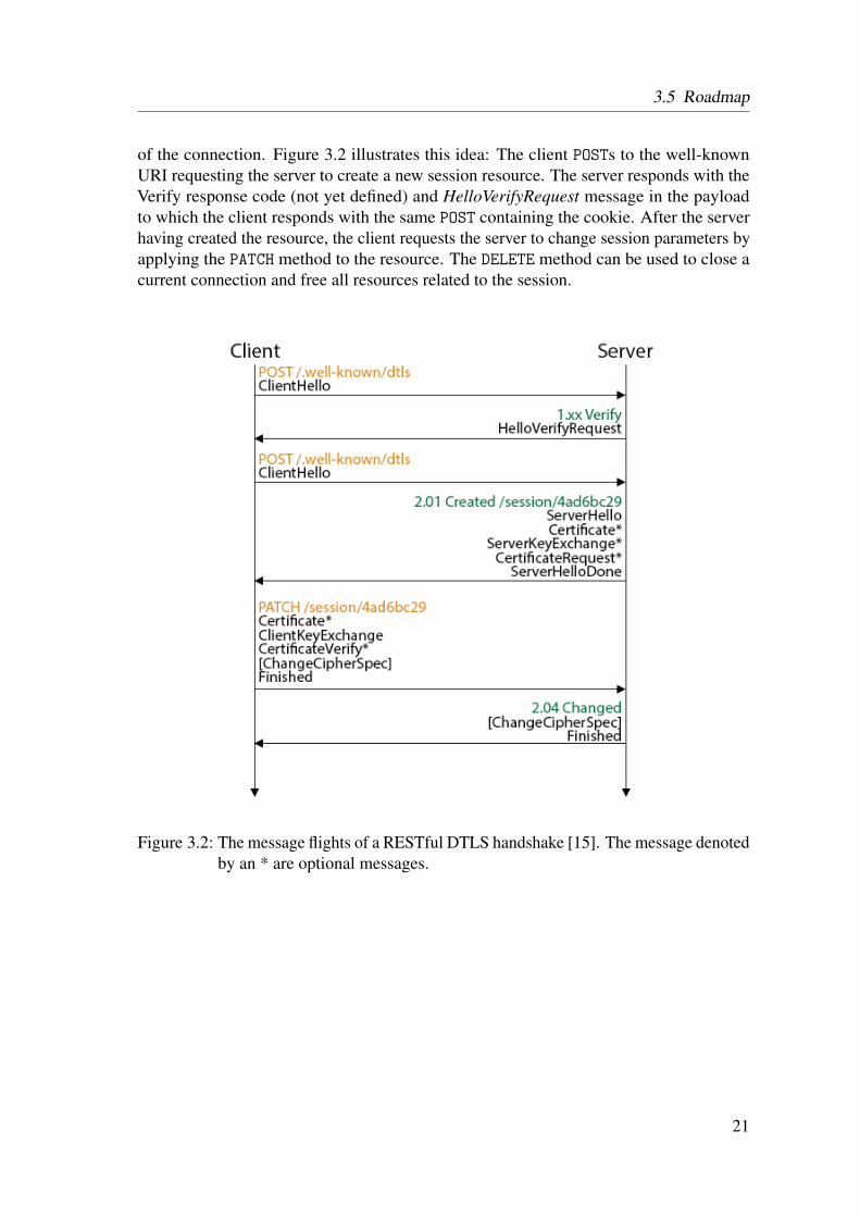
of the connection. Figure 3.2 illustrates this idea: The client POSTs to the well-knownURI requesting the server to create a new session resource. The server responds with theVerify response code (not yet defined) and HelloVerifyRequest message in the payloadto which the client responds with the same POST containing the cookie. After the serverhaving created the resource, the client requests the server to change session parameters byapplying the PATCH method to the resource. The DELETE method can be used to close acurrent connection and free all resources related to the session.
Figure 3.2: The message flights of a RESTful DTLS handshake [15]. The message denotedby an * are optional messages.
21

3 Security Survey
3.5.8 Templates
Hartke & Bergmann also proposed templates which could help make building and parsingthe bodies of Certificate, ServerKeyExchange and ClientKeyExchange simpler whenElliptic Curve Cryptography (ECC) is used. Instead of decoding and encoding theelliptic curve points according to the ASN.1 standard [11], which needs lots of memoryconsuming code, the static body parts of the message can be used to achieve this moreeasily. Unfortunately, after several tests, we had to detect that this cannot be achievedthat easily. Although the elliptic curve points have a fixed length, in the handshakemessage they must be encoded as a Distinguished Encoding Rules (DER) integer value.By definition, if the leftmost bit of an integer value is 1, an extra byte needs to be added tothe encoded value resulting in different lengths of the encoded points. So, using total staticpre-composed messages cannot work, but a more variable approach needs to be found, ifthis templates should be used in constrained environments.
We have presented several ideas on how to make the DTLS protocol more suitablefor constrained environments. Apart from the stateless header compression, changes tothe DTLS protocol specification need to be performed with greatest care. So far, noin-depth security analysis has been executed regarding these possible changes, which willbe essential before even thinking about implementing these ideas.
As we have now seen the different aspects of a secured Internet of Things (IoT) incombination with Constrained Application Protocol (CoAP) , we present the first steptowards such a secured environment: We implemented Datagram Transport Layer Security(DTLS) to secure CoAP during the operational phase.
22

4 DTLS for Californium
This chapter describes the design decisions which have been made to integrate DTLS intoCalifornium (Cf) . DTLS is a complex security protocol and requires detailed knowledgein various areas. We try to explain the most important features when they are needed, butthe reader is advised to read Appendix A previously to the following chapters, to gain anoverview about the DTLS handshake protocol and the used concepts.
4.1 Overview
As mentioned in Chapter 2, Cf uses a layered architecture to add functionality to thecommunication stack. Therefore, adding security to this stack implies just adding anotherlayer that takes care of this. The secured communication stack is shown in Figure 4.2.Compared to the unsecured communication stack in Figure 4.1, the UDPLayer has beenreplaced by the DTLSLayer. This decision implies that the DTLSLayer is responsible foradding the security feature as well as executing the job of the UDPLayer of sending themessage over the network. This decision of replacing the lowest layer instead of insertingthe DTLSLayer above the UDPLayer was mainly motivated by the newly introducesmessage formats of DTLS : The current layer interface can only handle CoAP messagesand to make message passing between the layers possible for both CoAP and DTLSmessages, would have needed a lot of changes to the layer architecture. So, as long as theDTLSLayer is the lowest layer in the communication stack, the other layers must not beable to handle DTLS messages as the DTLSLayer will only exchange CoAP messagesbetween the upper layers. Another reason for this decision is CoAP ’s binding of the coapsURI scheme and the default security port to DTLS : There exist different default ports forthe coap and coaps URI scheme and therefore, we need two different communicationstacks—or at least two different lowest layers—listening on different ports. Thus, theexpected message format on the different ports is known and the lowest layer must not beable to distinguish the formats to be able to parse the datagram correctly. So, currently,the UDPLayer is responsible for parsing CoAP messages listening on port 5683 and theDTLSLayer for DTLS messages on the standard security port, which has not yet beenstandardised [37].
23

4 DTLS for Californium
Figure 4.1: The individual layers of an un-secured CoAP communicationstack.
Figure 4.2: The individual layers of a se-cured CoAP communicationstack.
4.2 DTLS Layer
Figure 4.3 provides a schematic overview of the whole DTLS architecture. The differentconcepts used in this graphic are explained in the following chapters.
The DTLS Layer works roughly as follows:
1. When the DTLSLayer receives a CoAP message from the upper layer, it checkswhether a DTLSSession exists with the peer:
a) If an active DTLSSession is found, the DTLSLayer sends the CoAP messageas encrypted application data.
b) If a DTLSSession exists with the peer that has been closed already, the DTLS-Layer initialises a Handshaker to execute an abbreviated handshake to resumethe session.
c) If there is no such DTLSSession, a full handshake must be executed.
d) The newly initialised Handshaker, which is either of type ClientHandshakeror ResumingClientHandshaker (as listed in Figure 4.5), returns the DTLS-Flight to kick-start the handshake protocol which is sent to the peer by theDTLSLayer.
e) After a successful handshake, the CoAP message will be sent as applicationdata protected with the newly negotiated security parameters.
2. When a UDP datagram is received, the packet is parsed into one or more Recordsand each is processed in the following way:
24

4.2 DTLS Layer
Figure 4.3: Schematic overview of the DTLS layer.
a) If the Record contains application data, it is decrypted with the current readstate defined in the DTLSSession associated with this peer and the resultingCoAP message is delivered to the upper layer. If no such DTLSSession exists,the message is discarded.
b) If the content of the Record is of type handshake, the DTLSLayer forwardsthe message to the appropriate Handshaker associated with the peer. TheHandshaker processes the message according to the current handshake protocolstate and potentially returns a DTLSFlight, which is sent by the DTLSLayer tothe peer.
To summarise, the DTLSLayer is responsible for the following tasks:
• Receiving and delivering CoAP messages from the upper layer.• Sending and receiving of UDP datagrams and handling the serialisation.• Associating endpoint addresses with DTLSSessions, Handshakers and DTLSFlights.• Handling the retransmission timers and retransmitting the corresponding flight when
the timer expires.
25

4 DTLS for Californium
4.3 Handshaker
The Handshaker is responsible for the handshake logic and keeps track of the state ofthe current handshake execution between two endpoints. So, for each new handshakebetween two peers, a new Handshaker object must be generated. The Handshaker isdriven asynchronously by the handshake messages delivered to it by the DTLSLayer.The specific logic is implemented in the subclasses of the abstract class Handshaker byproviding implementations for the two abstract methods:
DTLSFlight processMessage(Record message)
This method is called by the DTLSLayer on the corresponding Handshaker objectwhen a handshake message is received that belongs to the handshake executionassociated to this handshaker. The handshaker processes the received messageaccording to its handshake message type and reacts corresponding to the currentstate of the handshake protocol. It returns the next DTLSFlight of the handshakeprotocol, if the currently processed message marks the last of the peer’s current flight.If an error occurred during the processing of the message, a HandshakeExceptionis thrown which will be caught and handled by the DTLSLayer.
DTLSFlight getStartHandshakeMessage()
This method returns a DTLSFlight containing the handshake messages needed tokick-start or resume a handshake, which will then be sent by the DTLSLayer.
Figure 4.5 depicts the four types of handshakers that implement these two methods:
ClientHandshaker
The ClientHandshaker executes a full handshake from the point of view of theclient. It will only allow to receive the following handshake messages: a) Hello-Request, b) HelloVerifyRequest, c) ServerHello, d) Certificate, e) ServerKeyEx-change, f) CertificateRequest, g) ServerHelloDone and h) Finished. All otherreceived messages will result in an aborted handshake. Its kick-start flight willcontain a ClientHello message with an empty session identifier.
ResumingClientHandshaker
The ResumingClientHandshaker executes an abbreviated handshake from thepoint of view of a client. It inherits certain client functionality by extending theClientHandshaker class but overrides the two abstract methods. It will onlyprocess these two messages: ServerHello and Finished. Its first flight will contain aClientHello message having a session identifier of a previous finished handshake.
ServerHandshaker
The server’s counterpart to the client’s full handshaker. It will only processthese handshake messages: a) ClientHello, b) Certificate, c) ClientKeyExchange,d) CertificateVerify and e) Finished. To ask the client to start a new handshake, theServerHandshaker sends a HelloRequest message.
26

4.4 DTLS Session
ResumingServerHandshaker
The server’s counterpart to the client’s abbreviated handshaker. It overrides theprocessMessage()method of the ServerHandshaker and can only process Client-Hello and Finished messages.
The abstract class Handshaker provides the general functionality and fields which willbe used by all types of handshakers when executing a handshake:
• Generation of the master secret from a given premaster secret and calculating thecorresponding read and write keys.• Handling reordering of messages by deciding whether the received message is the
next one that can be processed.• Wrapping handshake messages into record layers, handling the sequence number
and epoch, and apply fragmentation if needed.• Reassembling fragmented messages.• Loading of the private key and the according certificate which will be used in the
handshake protocol when authentication is required.• Providing buffers to queue messages and store fragmented messages.• Holding the shared keys when the PSK key exchange mode is used.
4.4 DTLS Session
The class DTLSSession represents a DTLS session between two peers. It keeps trackof the current and pending read/write states, the current epoch and sequence number forthe record that will be sent next, and the key exchange mode. Additionally, it holds thenegotiated Master Secret which can be used in abbreviated handshakes to derive freshkeys. The DTLSLayer stores all sessions that have been established during a successfulhandshake.
4.5 Record
The DTLS protocol exchanges Records, which are used to encapsulate the data that needsto be exchanged (e.g., handshake messages or application data). Depending on the currentconnection state, the Record is compressed, padded, MACed and encrypted. Each Recordhas a content type field that specifies the encapsulated protocol (i.e., handshake, alert,change cipher spec, or application data protocol), which is treated by the Record class asopaque data that needs to be dealt with by the specified higher-level protocol [10].
27

4 DTLS for Californium
4.6 DTLS Message
A DTLS message represents a generalisation of the four protocol message types whichare encapsulated in the Record layer (see Section 3.4.2). The corresponding interfaceDTLSMessage is used by the Record layer to hold the opaque protocol data. It is imple-mented by the four content types (see Figure 4.4):
Change Cipher Spec
The Change Cipher Spec protocol is used to signal transitions in ciphering states.The message is used by both client and server to notify the peer that all followingrecords will be protected under the negotiated security parameters. When receivingsuch a message, the read current state is changed to the read pending state.
Alert
Alert messages are used to notify the peer about problems or errors in the currenthandshake execution. Fatal alerts result in an immediate termination of the currentconnection while Warning alerts need to be evaluated: The recipient must judgewhether it is still safe to continue the current handshake given the specific warning.
Application Data
Application Data messages are treated by the Record Layer as transparent data. It iscompressed and encrypted based on the current encryption state. The DTLS Layerparses the decrypted application data and returns the CoAP message to the upperlayer.
Handshake
The Handshake Protocol is responsible for negotiating a session and generatingshared secrets which can then be used by the Record Layer to protect the applicationdata. To complete a full handshake (see Appendix A for the detailed protocol),several different handshake message types are needed; see Figure 4.4 for all themessage types.
The DTLSMessage defines one method which must be implemented by all four subtypes:
public byte[] toByteArray()
This method returns the raw binary representation of the message which is then usedby the Record layer protocol for potential compression and encryption.
Please note that each implementation of the DTLSMessage interface must also provide afromByteArray() method, but as this method is static, it is not defined in the interface.
28

4.7 DTLS Flight
4.7 DTLS Flight
A DTLS Flight represents a handshake protocol flight containing all handshake messagesthat need to be sent to the peer in the coming flight. See the Figure A.1 in Appendix Afor an example of a flight. One flight contains of at least one message and needs to beretransmitted until the peer’s next flight has arrived in its total. Although each flight ofmessages may consist of a number of messages, they should be viewed as monolithic forthe purpose of timeout and retransmission.
29

4 DTLS for Californium
Figure 4.4: The interface DTLSMessage andits implementations. Classes de-noted by an “A” are abstractclasses.
Figure 4.5: The abstract class Handshaker
and its subclasses.
30

5 Implementation
When we were planning the design and implementation phase, we were faced with onefundamental decision: Should we implement DTLS from scratch or should we take anexisting implementation of TLS and adapt it to the additional needs of DTLS . Suchan adaptation has been implemented by N. Modadugu and E. Rescorla. It requiredadding about 7000 lines of additional code to the OpenSSL base distribution [27], whichimplements TLS . We decided not to follow this road and instead implement DTLS fromscratch. This decision was mainly influenced by two factors: a) Changing an existingTLS framework such that the result is a light-weight DTLS implementation which canbe used in a constrained environment seems rather unlikely to be successful due to theinitial overhead. b) Although this DTLS implementation for Cf focuses on unconstrainedenvironments and may never be used in constrained environments, as porting Java code toC code is quite hard, we still hope to gain something out of this: Namely experience aboutthe design, the implementation and potential optimisations of the protocol. For readersinterested in the source code, it is publicly available on Github1.
5.1 DTLSLayer
As we have already mentioned in Chapter 4, the DTLSLayer is the lowest layer in thecommunication stack because it is responsible for sending and retrieving datagrams fromthe transport layer that resides beneath the application layer in which Cf resides. Therefore,it extends Cf ’s abstract class Layer and not like the upper layers the class UpperLayer.An UpperLayer has the additional method sendMessageOverLowerLayer(). Althoughit would be possible to add a layer below the DTLSLayer in the communication stack, wedecided that it must be the lowest layer whenever it is added to the stack. This decision hasmainly been made because DTLS introduces new message formats. As long as this can behandled at the lowest layer, it has no influence on the other layers. But if the DTLSLayershould have been interchangeable with upper layers, the interface for passing messagebetween the layers would have needed a lot of changes.
One of the main functionalities of the DTLSLayer is to distribute the received messagesto the corresponding Handshaker object and to store the DTLSSession objects. For thistask, it has two Maps that store Handshakers and DTLSSessions according to the peer’s
1https://github.com/mkovatsc/Californium/tree/security
31

5 Implementation
address. Whenever a message is received, the layer checks whether there exists an entryaccording to the peer’s address. If neither a DTLSSession nor a Handshaker exist, onlytwo handshake messages are allowed to be received:
ClientHelloThe peer wants to start a fresh handshake. Therefore, this entity will act as theserver: The DTLSLayer initialises a ServerHandshaker and DTLSSession, storesthem and forwards the message to the ServerHandshaker for processing.
HelloRequestThe peer indicates that it wants this entity to start or resume a handshake. Therefore,this entity will act as the client: The DTLSLayer initialises a ClientHandshaker
and DTLSSession, stores them and forwards the message to the ClientHandshakerfor processing.
All other messages will be discarded. If a DTLSSession exists, but no Handshaker, thehandshake must have been finished successfully and the session holds all the informationneeded to read the sent application data: The message is decrypted, the protected CoAPmessage extracted and forwarded to the upper layer. If an associated Handshaker exists,the layer forwards the received message to it for processing. Whenever a CoAP messageis passed down from an upper layer, the DTLSLayer must check whether a session existswith the endpoint. If so, the message is sent as protected application data, otherwise anew handshake is started: A ClientHandshaker is initialised and starts the handshakeby invoking the getStartHandshakeMessage(). The CoAP message is stored in theClientHandshaker and sent as application data once the handshake is finished. Ofcourse, there are more cases that must be distinguished, but those described are the mostcommon ones and should suffice to illustrate the responsibilities of the DTLSLayer.
As can be seen by these explanations, the DTLSLayer is symmetric. This means, thatwe do not need different stacks for client and server endpoints but both instances can behandled inside the same layer. This symmetry is essential because in machine-to-machineapplications endpoints may act as both client and server at the same time.
5.2 Cryptography
During the DTLS handshake and securing application data, a lot of different cryptographicalgorithms are needed, such as for: a) Digital signatures, b) encryption, c) certificates andcertificate validation, d) message digests (hashes), e) secure random number generation,and f) key generation and management.
32

5.2 Cryptography
Luckily, the Java Cryptography Architecture (JCA) provides a large set of APIs whichhelp integrating security into application code. Whenever possible, we relied our imple-mentation on this highly tested and maintained security platform, rather than trying toimplement such difficult cryptographic algorithms by ourselves. However, some featuresof DTLS depend on emerging standards that are not yet implemented.
5.2.1 Native Java Support
JCA 2 defines so called Engine Classes which provide the interface to a specific typeof a cryptographic service. We illustrate the use of such an Engine Class with theSignature class: To use a specific digital signature algorithm of JCA , the applicationsimply requests a particular type of object (here Signature) and a particular algorithm(such as SHA1withECDSA) and gets an implementation from one of the installed securityproviders. Concretely, this is done by using one of the Signature getInstance() staticfactory methods (line 1 in Listing 5.1). This static method is part of each Engine Classand is the starting point for each provided algorithm.
Before, we mentioned the concept of a Security Provider which needs explanationas well: A Security Provider implements some or all parts of Java Security. Each JavaDevelopment Kit (JDK) installation has one or more providers installed and configured bydefault. So, if no specific provider is selected, the installed providers are searched throughfor a requested service (in our case SHA1withECDSA for Signature) until one is foundthat supplies a concrete implementation thereof.
The rest of the example code in Listing 5.1 is a straightforward example on how toproduce a signature of some given data. The beauty in this approach lies within thefact that if we need another digital signature algorithm, only the first line needs to bechanged while the rest of the code remains untouched. Please note that the selectionsof the algorithm instances are not hardcoded in the implementation but depend upon thenegotiated ciphersuite.
Listing 5.1: Example Java code for the use of JCA.1 // get the required signature algorithm2 Signature signature = Signature.getInstance("SHA1withECDSA");3
4 signature.initSign(privateKey);5 signature.update(new byte[] {});6
7 // the signature of an empty byte array8 byte[] signatureEncoded = signature.sign();
2http://docs.oracle.com/javase/7/docs/technotes/guides/security/crypto/CryptoSpec.html
33

5 Implementation
5.2.2 Own Implementation
As mentioned earlier, certain required cryptographic algorithms for DTLS are not yetimplemented in JCA . Therefore we had to decide whether to use an external library (e.g.,Bouncy Castle3) or to implement the missing functionality by ourselves. For the sake offuture use of this implementation in constrained environments, we decided to implementit ourselves which should result in a more lightweight solution than including an externallibrary. The following algorithms had to be implemented:
Hash-Based Message Authentication Code (HMAC)HMAC is a mechanism for message authentication using cryptographic hash func-tions, such as MD5 or SHA-256, in combination with a secret shared key [22]. Ourimplementation makes use of the available implementations for the underlying hashfunctions and needs only to append the resulting byte streams correctly according tothe protocol. The test vectors supplied in [22] have all been passed.
Pseudorandom Function (PRF)The PRF is defined in [10] and plays a crucial role in generating the Master Secret,key material, or verify data needed in the Finished message used in the DTLShandshake. The PRF is defined as follows:
PRF(secret, label, seed) = P_<hash>(secret, label + seed), withP_hash(secret, seed) = HMAC_hash(secret, A(1) + seed) +
HMAC_hash(secret, A(2) + seed) +HMAC_hash(secret, A(3) + seed) + ...
where + indicates concatenation.
A() is defined as:A(0) = seedA(i) = HMAC_hash(secret, A(i-1))
P <hash> denotes a data expansion function that uses a single hash function toexpand a secret and seed into an arbitrary quantity output. HMAC uses this saidhash algorithm as described above. The PRF can be used in the following manner:
master_secret = PRF(pre_master_secret, "master secret",ClientHello.random + ServerHello.random)[0..47];
Counter with CBC-MAC (CCM)CCM (Counter with Cipher Block Chaining Message Authentication Code) is anauthentication encryption block cipher mode designed to provide both authenticationand confidentiality [42]. It is only defined for block ciphers with block length of128 bits, such as Advanced Encryption Standard (AES) . The ciphersuites named* WITH AES 128 CCM 8 uses AES-128 as the block cipher and uses 8 octets (64
3http://www.bouncycastle.org/
34

5.3 Ciphersuites
bits) for authentication resulting in a ciphertext that is 8 octets longer than thecorresponding plaintext. For the underlying cipher the available implementation ofJCA is used (e.g., AES ). The test vectors defined in [42] have all been passed.
It is important to note that certain native Java cryptographic functions, upon which thisimplementation relies, are not available before Java 7. Mainly, this includes all functionsusing Elliptic Curve Cryptography (ECC) .
5.3 Ciphersuites
A ciphersuite is a named combination of key exchange, authentication, encryption, andmessage authentication algorithms. It is used to negotiate the security settings underwhich the DTLS handshake will be executed. The CoAP draft declares two ciphersuitesto be mandatory: TLS PSK WITH AES 128 CCM 8, as specified in [12] and [25], andTLS ECDHE ECDSA WITH AES 128 CCM 8, as specified in [6], [10] and [25].
5.3.1 TLS PSK WITH AES 128 CCM 8
This ciphersuite uses the PSK key exchange algorithm to establish the Master Secret. Thisresults in a simplified handshake protocol (compared to the one described in AppendixA): Since both parties have pre-shared keys exchanged in the past, the need for mutualauthentication can be omitted (no ServerCertificate, CertificateRequest, ClientCertificateand CertificateVerify message needed) because trust in the other party must have beenestablished beforehand. By trust we mean basically authenticity: If the peer possessesthe pre-shared key, it must have been distributed previously in a secure way (e.g., duringthe bootstrapping phase) where the peer must have authenticated itself. An attacker mayindeed impersonate the peer, but has no way of guessing the pre-shared key correctly andfinishing the handshake successfully, rendering authentication unnecessary. Additionally,the ServerKeyExchange message can also be left out, unless there exist multiple pre-sharedkeys between the client and the server, and the server wants to help the client in selectingthe appropriate one by providing a PSK identity hint. If no such hint is provided by theserver, the client selects one key and indicates this by including a PSK identity in theClientKeyExchange message. The storing and retrieving of pre-shared keys has beensolved so far in a very simple way: A HashMap which stores keys according to PSKidentities.
protected static Map<String, byte[]> sharedKeys =new HashMap<String, byte[]>();
Currently, the server never sends a PSK identity hint and the client’s PSK identity isdetermined using the Properties file (see 5.8). This solution with hardcoded pre-shared keys in the source code might work for testing purposes but is obviously not
35

5 Implementation
suitable for larger and dynamically changing networks. A more flexible solution must befound to add pre-shared keys. This problem needs to be solved during the bootstrappingphase of the network and since this implementation focused on the use of DTLS duringthe operational phase, finding solutions has been ignored so far and will be subject offuture works.
While generating the Master Secret from a given Premaster Secret is the same for allciphersuites, the generation of the Premaster Secret is specific to the used ciphersuite.The Premaster Secret is formed as follows: If the PSK is N octets long, concatenate auint16 with the value N, N zero octets, a second uint16 with the value N, and the PSKitself [12]. To illustrate this, if the PSK is { 0x01, 0x02, 0x03 } the PremasterSecret will become:
{ 0x00, 0x03, 0x00, 0x00, 0x00, 0x00, 0x03, 0x01, 0x02, 0x03 }<--- N --> <--- N zero ---> <--- N --> <---- PSK ----->
The 2-byte identifier of the ciphersuite used in the Hello messages is 0xC0,0xA8 asspecified by the Internet Assigned Numbers Authority (IANA) [40].
5.3.2 TLS ECDHE ECDSA WITH AES 128 CCM 8
This ciphersuite uses the Elliptic Curve Diffie-Hellman (ECDH) key agreement to generatethe Premaster Secret, and Elliptic Curve Digital Signature Algorithm (ECDSA) as theauthentication mechanism. For detailed explanations about this handshake and the usedECC mechanisms, please refer to Appendix A and B. Luckily, Java provides native supportfor almost all mechanisms that are needed to use this ciphersuite:
• Generating ephemeral ECDH key pairs used for the key agreement.• Executing the key agreement protocol and generating the Premaster Secret.• Creating an ECDSA signature and validating it.
We only had to implement two things on our own:
EncodingTo run the ECDH key agreement algorithm with ephemeral keys, both the client andthe server must supply the other party with their public key which represents a pointon the negotiated elliptic curve. When the key exchange object is serialised, thispoint must be encoded according to the conversion routine of ANSI X9.62 [6] whichis not supported by Java. Since the conversion is straightforward (and thereforeposes low risk to a faulty implementation), we decided to implement it ourselvesinstead of relying on an external library.
36
5.4 Certificates
Named Curve ParametersA named curve specifies the domain parameters for one specific elliptic curve.This comes in handy when the server sends its ephemeral public key and the usedelliptic curve parameters in the ServerKeyExchange message: Instead of sendingthe complex domain parameters in its entirety, the server needs only to transmitthe named curve identifier. Although Java provides the ECParameterSpec classwhich is designed to hold the domain parameters of an elliptic curve, a lookup tablefor named curve identifiers does not exist. Therefore, we decided to create such astatic lookup table which maps identifiers to parameters:
public final static Map<Integer, ECParameterSpec>NAMED_CURVE_PARAMETERS;
The elliptic curve domain parameters have been defined by Standards for EfficientCryptography Group and can easily be used to initialise the needed ECParameter-Specs [38].
The 2-byte identifier of the ciphersuite has not yet been defined [40] by IANA , but fornow we used the next available value 0xC0,0xAC.
5.4 Certificates
To achieve authentication, the DTLS handshake protocol specifies the Certificate message.It contains a certificate chain of X.509 certificates where the first certificate in the chaincontains the peer’s public key. To make the loading as easy as possible we decided touse Java keytool which is a key and certificate management tool that manages a keystore(database) of cryptographic keys, X.509 certificate chains, and trusted certificates4.
For our purpose, there exist two keystore files: The keystore containing a private keyand a certificate chain with the first certificate having the corresponding public key, andthe truststore that contains all trusted certificates. Appendix C shows how to use thekeytool and openssl commands to generate a keystore containing a certificate chainsigned by a trusted certificate authority. Loading of the certificate chain and private keycan then be easily achieved by the use of alias given to the private key and certificatechain. The Java code in Listing 5.2 illustrates this.
As described in [44], the use of raw public keys could be a good solution for DTLSused in constrained environments: Instead of sending a large X.509 certificate chain toachieve authentication, an entity can send only its public key in the Certificate messagewhile the validation of the public key is achieved by an out-of-band method. This case canbe handled almost the same way as sending the whole certificate chain. The loading of
4http://docs.oracle.com/javase/7/docs/technotes/tools/windows/keytool.html
37

5 Implementation
Listing 5.2: Example Java code for loading the private key and certificate chain.1 KeyStore keyStore = KeyStore.getInstance("JKS");2 // path loaded from Californium.properties file3 InputStream in = new FileInputStream("path/to/keyStore");4 keyStore.load(in, "password");5
6 Certificate[] certificates = keyStore.getCertificateChain("alias");7 PrivateKey privateKey = keyStore.getKey("alias", "password");
the certificate through the keystore can be done the same way as already explained andextracting the public key can be achieved easily:byte[] rawPublicKey = certificateChain[0].getPublicKey().getEncoded();
The getEncoded() method applies the right encoding to the public key, namely usingthe ASN.1 DER according to the X.509 standard [9], and therefore the raw public key canbe added to the payload of the Certificate message without any further modifications.
Please note that the proposal for the use of raw public keys still had the status of anInternet-Draft when this thesis was written and therefore the concept has not been fullydefined. Up to draft number 4, it has not been defined whether the raw public key adoptsthe format structure of the Certificate message or whether the payload of the handshakemessage only consist of the raw public key. The authors of this Internet-Draft stated thatthis is not clear yet and needs to be specified in a later version of the draft.
5.5 Error Handling
Error handling is a crucial part of the DTLS handshake protocol, since there are severalpoints where failures must be expected during the protocol. In general, there are twopossible source of errors:
Handshake ExceptionsThese type of exceptions are thrown intentionally during the handshake. Potentialerrors can occur when: a) Authentication of the cipher failed. b) The receivedcertificate chain could not be validated. c) A signature could not be verified.d) No Pre-Shared Key was found. e) Wrong ECDH parameters used by peer.f) The verify data in the Finished message does not match. g) UnknownHelloExtension type received. h) Unsupported version negotiated. i) Nosuitable ciphersuite found. j) Unexpected handshake message received.
38

5.6 Serialisation
All these errors lead to a FATAL Alertmessage and therefore to the abortion of thecurrent handshake. In all cases, a HandshakeException must be thrown withthe error-specific AlertMessage, e.g., when the cipher could not be authenticated(Listing 5.3).
Unexpected ExceptionsExceptions suitable for this category happen unexpected and can occur at anyparticular point in the protocol. The Java Virtual Machine (JVM) throws thecorresponding exception when such an error happens. The most common exceptionis the NullPointerException which mainly occurs due to parse errors.
Listing 5.3: Example Java code illustrating how to react upon failed cipher authentication.1 String message = "The encrypted message could not be authenticated";2 AlertMessage alert = new AlertMessage(AlertLevel.FATAL,
AlertDescription.BAD_RECORD_MAC);3 throw new HandshakeException(message, alert);
All possibly thrown exceptions are caught at a single point in the DTLSLayer. Tomake the DTLSLayer stable against unexpected errors, the whole method that receivesthe datagram, parses the message and reacts according to the message, is surround with atry/catch block that catches all possible exceptions. If the caught exception is an instanceof the HandshakeException, the specified alert will be sent to the peer, otherwisethe general alert HandshakeFailure.
5.6 Serialisation
Serialisation describes the process of converting an object (e.g., Record or DTLS-Message) into its raw binary representation to be sent over the network and later to bereassembled into an identical clone of the object at the peer’s side. For this purpose, eachobject representing a DTLS message must have the following two methods:
toByteArray()This method returns the byte representation of the specific object. It implements theprotocol data structures defined in [10, 33].
fromByteArray()This is the inverse function of the above one: It reads the received byte array streamand reconstructs the given object.
39

5 Implementation
As mentioned, (D)TLS specifies data structures for each handshake message and howthe serialisation is realised. Structure types are fundamentally constructed from primitivetypes and each specification declares a new, unique type. The syntax for definition is muchlike that of C:
struct {T1 f1;T2 f2;...Tn fn;
} [[T]];
One of the important data structures is a vector which represents a stream of homoge-neous data elements. There are two types of vectors:
Fixed-lengthThe syntax for specifying a new type T’ that is a fixed-length vector of T is:T T’[n];Here, T’ occupies n bytes, where n is a multiple of the size of T. Since, the lengthis fixed by definition, the length of the vector is not included in the encoded stream,unlike for the second type of vectors.
Variable-lengthVariable-length vectors are defined by specifying a sub-range of legal lengths, inclu-sively, using the notation <floor..ceiling>. Since the length will be variable,the encoded stream of the vector must be prepended with a number consumingas many bytes as required to hold the specified maximum length of the vector.Otherwise, the decoding process would not work as it would be unclear how manyelements the following vector contains. An example should illustrate this easily:uint16 longer<0..800>;This represents a vector of 0 up to at most 400 16-bit unsigned integers (800 isthe maximum allowed length of the whole vector, not the maximum number ofelements). First, we have to determine how many bytes are needed for the lengthfield: The maximum length of the vector cannot be represented using just 1 byte(maximum length would be 255 for 1 byte), but 2 suffice (65535) to express themaximum length of the vector. This 2-byte length field is prepended to the actualvector. So, the vector [1, 2, 3, 4] would be encoded to:
0x00, 0x04, 0x01, 0x02, 0x03, 0x04<-length-> <-------vector------->
Now, let us look at a concrete example on how serialisation is realised and what mustbe considered. We will use one of the most simple handshake messages, the HelloVerify-Request: Listings 5.4, 5.5 and 5.6 show the definitions of the data structures which will beneeded for this message.
40

5.6 Serialisation
Listing 5.4: The Record Layer data structure.struct {ContentType type;ProtocolVersion version;uint16 epoch;uint48 sequence_number;uint16 length;opaque fragment[DTLSPlaintext.length];
} DTLSPlaintext;
Listing 5.5: The Handshake Protocol data structure.struct {HandshakeType msg_type;uint24 length;uint16 message_seq;uint24 fragment_offset;uint24 fragment_length;select (HandshakeType) {
case hello_request: HelloRequest;case client_hello: ClientHello;case hello_verify_request: HelloVerifyRequest;case server_hello: ServerHello;case certificate:Certificate;case server_key_exchange: ServerKeyExchange;case certificate_request: CertificateRequest;case server_hello_done: ServerHelloDone;case certificate_verify: CertificateVerify;case client_key_exchange: ClientKeyExchange;case finished: Finished;
} body;} Handshake;
Listing 5.6: The HelloVerifyRequest data structure.struct {ProtocolVersion server_version;opaque cookie<0..2ˆ8-1>;
} HelloVerifyRequest;
Figure 5.1 depicts the serialisation of the listed data structures. One can see that thetransformation is quite straight forward, as almost all field definitions are clear. The onlypotential pitfall is the field opaque cookie<0..2ˆ8-1> defined in the HelloVerify-Request data structure. Since this field is a variable-length vector, we need to add a 1-bytelength field in front of it. 1 byte suffices since the maximum specified length of 2ˆ8-1can be represented using 1 byte only.
So, in our implementation, serialisation is done by calling the toByteArray()method of the record that is responsible for the record header, which will then callthe handshake message’s toByteArray() function that will be responsible for the
41

5 Implementation
handshaker header and the underlying handshake message. De-Serialisation is donein the same way by invoking the fromByteArray() method. Please note that thetoByteArray() method is dynamically bound according to the type of the handshakemessage, while the fromByteArray() is a static method defined in the abstract classHandshakeMessage which calls the fromByteArray() method of the subclassaccording to the read msg type field.
Figure 5.1: Serialisation of the HelloVerifyRequest with the handshake and record headers.The field Content Type will have the value 22 (standing for handshakemessage) and the field Handshake Type the value 3 (indicating a Hello-VerifyRequest inside the handshake message data).
The challenge in implementing the serialisation lies in the diversity of the handshakemessages: There are eleven handshake messages defined, several of them far more complexthan the presented HelloVerifyRequest. Also, certain messages have different formatsaccording to the used key exchange algorithm. Thus, implementing all variations, gettingeverything right as specified, and testing all the message formats was one of the greatestchallenges faced during the implementation.
42

5.7 Fragmentation
5.7 Fragmentation
Fragmentation has been specified in [33] to avoid IP fragmentation: Each DTLS messagemust fit within a single transport layer datagram. Since certain handshake messages arepotentially bigger than the maximum record size (mostly X.509 Certificate messages),DTLS provides a mechanism for fragmenting a handshake message over a number ofrecords. In order to support fragmentation, DTLS modified the TLS 1.2 handshake headerby adding two new fields:
fragment offsetIndicates the number of bytes contained in the previous fragments. The first fragmentstarts with the fragment offset = 0.
fragment lengthSpecifies the length of this fragment and must not be larger than the maximumhandshake fragment size.
All fragments have the same message seq value as the original message; the same istrue for the length field in the handshake header. An unfragmented handshake messagetherefore has fragment offset = 0 and fragment length = length.
To implement fragmentation, the class FragmentedHandshakeMessage, whichextends the abstract class HandshakeMessage (see Figure 4.4), had to be created. Itserves as storage data structure that contains one part of the fragmented message whichis transparent to the object holding it. Before the handshake message is wrapped into aRecord layer, it is checked whether the handshake message is larger than the maximumrecord size. If so, the message is divided into a series of N contiguous data ranges (hold bythe FragmentedHandshakeMessage) which are then sent as N separate Recordsover the network. When a fragmented handshake is received—identified by the fact thatfragment length 6= length—it is buffered until all fragments have arrived. Sinceall fragments of the same original message have the same message seq value, they canbe stored according to this value using a Map.
protected Map<Integer, List<FragmentedHandshakeMessage>>fragmentedMessages;
Because of potential reordering of the handshake messages, each time a fragmented mes-sage has arrived, it must be checked whether all fragments have been received to reassem-ble the original message. Therefore, the list of FragmentedHandshakeMessage isordered by the fragment offset field and then iterated over to reassemble the originalbyte array. If the size of the reassembled byte array equals the size of the original message,the unfragmented HandshakeMessage object can be reconstructed by calling the cor-responding fromByteArray() method. While iterating over the fragments ordered bythe fragment offset, one needs to take care of two special cases: a) The same frag-ment could be received multiple times, or b) the fragments could have overlapping ranges.
43

5 Implementation
These two cases can be handled by remembering the next expected fragment offsetvalue, which is initially set to 0. A fragmented message can be used to reassemble thewhole message when one of these cases is true:
1. No overlapping: The offset of the fragment is equal to the next expected offset.2. Overlapping: The offset of the fragment is less than the next expected offset, but
its offset in addition with its fragment length is greater than the expected offset. Inthis case, it is important to use only the bytes that do not overlap with the alreadyreassembled part of the message.
If the message could be used, the next expected fragment offset value is set to thecurrent length of the reassembled part of the message.
5.8 Properties
The class Properties implements Cf ’s property registry which is used to manageCoAP - and Cf -specific constants in a central place. The properties are initialised in theinit() section and can be overridden by a user-defined .properties file. If the filedoes not exist upon initialisation, it will be created so that a valid configuration alwaysexists. To make the use for DTLS easy configurable, the main security parameters definingthe protocol have been added to this registry. These are the following (with the standardvalues in brackets):
USE RAW PUBLIC KEY (false)Indicates whether the client wants to receive and potentially send its Certificatemessage containing only the public key or the full X.509 certificate chain. Ifthe value is set to true, the client will send the cert type in its ClientHelloextension which will contain at first position the raw public key certificate type andat second the X.509 indicating that it is capable of processing both raw public keyand X.509 certificates, but prefers to receive raw public keys. If the server supportsraw public keys as well, its ServerHello message will contain the cert typeextension containing the RawPublicKey certificate type, otherwise the extensionmay be omitted [44].
CLIENT AUTHENTICATION (false)This parameter defines whether the server requires the client to authenticate itself.This parameter is only decisive, if a ciphersuite has been selected that requiresauthentication (e.g., TLS ECDHE ECDSA WITH AES 128 CCM 8). Thus, if thisparameter is set to true and the server has sent its Certificate message, it sends aCertificateRequest message to the client and expects in the client’s next flight anadditional Certificate and CertificateVerify message; otherwise the handshake willbe aborted.
44

5.8 Properties
KEY STORE LOCATION (path/to/keyStore.jks)This gives the location where the keystore file is found. Normally, this should bean absolute path, unless the keystore is packed within the executable Java Archive(JAR) file. The keystore file is used to load the entity’s private key and certificatechain (see 5.4 Certificates). Not providing any keystore file is acceptable, as long asa ciphersuite is chosen, where the certificate chain and private key is not needed (e.g.,TLS PSK WITH AES 128 CCM 8); otherwise it will result in a failed handshake.
TRUST STORE LOCATION (path/to/trustStore.jks)Indicates the location of the truststore file (described in 5.4 Certificates). Thetruststore file contains all the trusted CAs certificates. If this file is not providedand the entity requires peer authentication, the certificate chain cannot be validated(unless self-signed certificates are accepted).
PREFERRED CIPHER SUITE (TLS PSK WITH AES 128 CCM 8)In the ClientHello message, the client provides a list of supported ciphersuitesordered by preference. Since the current implementation only supports two cipher-suites, this parameter suffices to configure which one is preferred. In future versions,when more ciphersuites will have been implemented, this should be made moreflexible to configure the list more easily.
MAX FRAGMENT LENGTH (200)This value defines the maximum length in bytes a handshake message fragmentis allowed to have without being sliced into multiple fragments (see 5.7 Frag-mentation for details). Please note, that this value indicates an upper limit forthe fragment length field in the handshake header, not the size of the totaltransport layer datagram.
RETRANSMISSION TIMEOUT (1000)The retransmission timeout is defined in milliseconds and indicates the amount oftime which can elapse for the peer to successfully send the whole flight. After this,the current flight is retransmitted and the timer reset. The value of 1000 millisecondsis recommended in [33].
PSK IDENTITY (PSK Identity)If a PSK key exchange algorithm is used to establish the Master Secret, the clientmust include in its ClientKeyExchange message an psk identity indicatingwhich pre-shared key to use. If this value is not given, the server will not find apre-shared key which will lead to an aborted handshake.
45

5 Implementation
5.9 Providing Reliability
The TLS handshake is a lockstep cryptographic handshake: Messages must be transmittedand received in a defined order—any other order is an error. Clearly, this is incompatiblewith the unreliable datagram traffic used in DTLS , namely reordering and message losscan happen. For both these problems, DTLS provides fixes.
5.9.1 Message Loss
Figure 5.2: An example on how packet loss is handled: If the client’s message is lost, theserver will retransmit its last entire flight after the timer expires. The clientwill retransmit its entire flight as well when it receives a retransmit.
Figure 5.2 shows how message loss is handled in DTLS : It uses a simple retransmissiontimer to handle packet loss. After having sent the last message of the current flight,the server starts a retransmission timer. While the timer is running, the client receivedthe server’s whole flight (with the ServerHelloDone being the last message), therefore
46

5.9 Providing Reliability
cancelling its timer for its previous flight and preparing to send the next flight. The serverreceives both the ClientKeyExchange and ChangeCipherSpec message and expects now tosee the client’s Finished message. However, after the timer has expired and the messagehas not yet arrived, the server knows that the Finished message must be lost, because somemessages of the client’s current flight have already arrived. Therefore, it retransmits thewhole flight to signal to the client that message loss has occurred. When the client receivesthe retransmissions, it knows it must retransmit. This message loss would also be handledby the client’s timer, if for some reason the server would not retransmit in time.
Concretely, this problem is solved in our implementation with the classes Timer andTimerTask: Every time a new DTLSFlight is sent, the timer schedules a task thatwill be execute in the future (after the current timer value has expired). When the timerfires, it calls the run() method of the task that retransmits the current flight, adjusts thetimeout and schedules a new retransmission task, if the maximum number of re-tries isnot reached yet. When the last message of the peer’s current flight is received, the currenttask is cancelled, the new flight is being sent, and a new retransmission task scheduledcontaining the current flight.
The timer value is a very delicate choice: A too small value can lead to seriouscongestion problems when each instance time out early and retransmit too quickly althoughno message loss has occurred. On the other hand, a too large value can cause really longround-trip times if message loss happened. The DTLS specification suggests an initialtimer value of 1 second and to double the value at each retransmission, up to no less thanthe maximum of 60 seconds [33]. This is currently implemented in this way, but futuretests in constrained environments will show whether this value needs adjustment.
5.9.2 Reordering
In an unreliable network, messages can arrive in a different order than they were sent out.A TLS implementation would break in such an environment since the order of processingthe messages is crucial for the correctness of the protocol. Therefore, DTLS has made afew adjustments to the record and handshake header to handle reordering:
EpochThe epoch field is a counter value which is incremented on every cipher statechange; so, each time a ChangeCipherSpec message is sent. This field was intro-duced to the record header. It is used to distinguish from which encryption state themessage comes: Only messages coming from the same epoch as the current readstate can be understood correctly, as for each new epoch the write state of the senderwill change.
47

5 Implementation
Sequence NumberThe sequence number field is the current sequence number for this record.Sequence numbers are maintained separately for each epoch, with each sequencenumber initially being 0 for each epoch. Please note, that for each retransmit, thesequence number must be incremented.
Message Sequence NumberThe message seq field was introduced in the handshake header and keeps trackof the handshake message counter during a handshake: Every time a new mes-sage is generated, the message seq value is incremented by one. While thesequence number must be incremented for each retransmit, it is important tonote that the message seq value stays the same for each retransmit.
So, how do these new fields help handling reordering? The concatenation of the epochand sequence number field make up an explicit sequence number, in contrast to TLSwhere such a sequence number can be established implicitly due to the reliable transportchannel. If only reordering would happen, this explicit sequence number would sufficeto handle it. But, in combination with message loss, we need the message seq valueas well. This is solved in our implementation with the processMessageNext()method in the Handshaker class. Whenever a new message is received, this methodis called to determine what to do with the incoming message: Basically, there arethree options: a) Process it right away, b) queue it for later processing, or c) discardit. To determine this correctly, we need two values: The current epoch which is storedin the DTLSSession associated with this handshake, and the next receive seqcounter which is stored in the Handshaker. This counter is initially set to zero andkeeps track of the next message seq value which is expected to be processed. TheprocessMessageNext() method works as follows: If the epoch value of the mes-sage, compared to the current epoch, is:
lessThe message is discarded since it comes from an older epoch and therefore must bea retransmit.
greaterThe message is queued for later processing. It must have arrived earlier due tomessage reordering. It is important to note that since the message comes from afuture epoch, the current read state is not compatible with the write state the messagewas encrypted with. Therefore, the handshake message contained inside the recordcannot be understood yet.
equalThe handshake message can be understood since the read and write states of themessage are the same. We now need to examine the message seq value in thehandshake header.
48

5.9 Providing Reliability
If the message seq matches the next receive seq, the counter is incrementedand the message is processed. If it is less than next receive seq, the message mustbe discarded, but since it marks a retransmit, the whole flight must be sent again. Ifit is greater than next receive seq, the message is queued. Figure 5.3 illustratesthe handling of the sequence number, message seq, and next receive seqcounter. Please note that queuing for future messages is not defined to be mandatory in theDTLS specification [33]; the message may also be discarded. This is a space/bandwidthtrade-off which might be interesting to examine for a constrained environment.
Queued messages are stored in a Collection<Record>. Every time a new messagehas arrived that could not be processed, or a message has been processed that did nottrigger a new flight to be sent, the whole queue is scanned for the next needed message.If this message is available in the queue, it is removed and processed. Special cautionmust be taken when a fragmented handshake message is received. The next receive -seq must only be incremented when all fragments of the messages have arrived, notbeforehand.
Figure 5.3: An example on how to handle reordering and retransmits: A message is onlyprocessed when the epoch and message seq match the expected values;otherwise the message is either queued or discarded. Also note the value ofthe sequence number: It increases with each retransmit while the value ofthe message seq remains the same for each retransmit.
49


6 Analysis
6.1 Testing
The security of DTLS relies upon the security of TLS since it is designed to be as similarto TLS as possible. Therefore, mainly the security considerations of TLS need to beconsidered. Appendices D and E of [10] list possible implementation pitfalls and makerecommendations for implementations to ensure security. Those have been followed verycarefully to avoid attacks based upon false implementations of the specifications.
6.1.1 Interoperability Tests
Regarding the security considerations of TLS (Appendix F of the TLS 1.2 specification),an implementation is secure as long as the specification has been followed correctly [10].To completely verify the conformation to the specification seems to be almost impossible,because the protocol is very complex and offers lot of pitfalls. Thus, we conducted variousinteroperability tests with other implementations which resulted in an increased confidence,that the specification has been implemented correctly. Table 6.1 shows what could havebeen tested:
PSK
EC
DH
E
Mut
ualA
uthe
ntic
atio
n
Frag
men
tatio
n
Raw
Publ
icK
eys
SICS X X X
TinyDTLS X
Silicon Labs X X
Table 6.1: Summary of the interoperability tests.
51

6 Analysis
Swedish Institute of Computer ScienceAt the Swedish Institute of Computer Science (SICS) , Shahid Raza and DanieleTrabalza have been implementing DTLS in Java. Together, we conducted veryexhaustive interoperability tests which were spread over a month of testing andfixing of our implementations. Lots of implementation problems could be identifiedand clarified together resulting in successful interactions for both mandatory cipher-suites TLS PSK WITH AES 128 CCM 8 and TLS ECDHE ECDSA WITH AES -128 CCM 8. Additionally, mutual authentication with trusted certificate authoritieshas been successfully tested.
TinyDTLSTinyDTLS is one of the first open-source implementations of the DTLS protocolfor small devices [13] realised by Olaf Bergmann at TZI Uni Bremen1. Only theTLS PSK WITH AES 128 CCM 8 ciphersuite could be tested for interoperabilitywith our implementation, since tinyDTLS lacks the support for any other ciphersuiteand key exchange method.
Californium (Cf) Interop ServerAn interop server has been set up at http://vs0.inf.ethz.ch/ to give otherimplementations the possibility to test their product against ours. This is primarilydone trying to expose flaws in either our or their implementation and test how ourimplementation handles faulty data.
Silicon LabsAfter having set up the interop server, Silicon Labs2 successfully tested their DTLSimplementation, which is based on a well-tested TLS 1.2 implementation, againstour server. As their source code is not publicly available, testing our client againsttheir server implementation was not possible.
As can be seen in Table 6.1, two important features introduces by DTLS could notbe tested with other implementations: fragmentation and raw public keys. This problemarose mainly due to unfortunate timing: Several DTLS implementations are currentlyin development, but not yet finished. The next deadline for mostly all of them will bethe end of November 2012 when the next ETSI/IPSO Plugtest3 will be held and DTLSimplementations will be tested for the first time. Thus, these features will be tested afterthe end of this thesis. Yet, we are confident that the fragmentation works correctly althoughwe could not test it with other implementations. Wireshark4, a network protocol analyserthat supports DTLS message parsing, is able to reassemble the fragmented messagesproperly. So, potential implementation errors like wrong fragment offsets can be ruled out.Unfortunately, Wireshark still lacks the support for raw public keys.
1http://tinydtls.sourceforge.net/2http://www.silabs.com/3http://www.ipso-alliance.org/nov-29-30-etsiipso-coap-plugtest-sophia-antipolis-france4http://www.wireshark.org/
52

6.2 Performance
6.1.2 Fuzz Testing
The problem with interoperability tests is that the other implementations behave generallyas expected. So, the implementation seems to work correctly as long as every step isexecuted as specified by the protocol. But like this, faulty data or wrong execution stepsare not ruled out to compromise the implementation. To address this issue, we ran differentfuzz tests where the implementation is fed invalid or random data at certain steps in theprotocol. The goal of these test runs was to check that the server cannot be crashed orcompromised. All of the tests ended with the server aborting the handshake by sending anAlert message to the peer containing a fatal handshake failure message. Also, in all cases,the server was able to continue operating normally after the test was run.
6.1.3 Unit Testing
DTLS is a very complex protocol which must be tested in its entirety to ensure itscorrectness. This is mainly done by the described interoperability tests. Still, certainindividual parts of the implementation, which are crucial for the correctness, are testedin separate unit tests. We limit ourselves to the cryptographic features that have beenimplemented by us and assume that the used functionality of JCA has been implementedcorrectly. The unit tests cover the following functionalities:
• Pseudorandom Function,• Hash-Based Message Authentication Code,• Counter with CBC-MAC, and• Serialisation of numeric data types.
The existing test cases5 [22, 42] for these functionalities have all been passed.
6.2 Performance
6.2.1 Setup
Measuring the performance of the implementation and comparing it to other implementa-tions would be an interesting reference point on how well our implementation operates.There are problems to realise this goal: a) By now, only a few DTLS implementationsexist (most of them only support TLS PSK WITH AES 128 CCM 8) and no standardisedbenchmarking has been realised so far. b) Since the TLS handshake is quite compute-intensive, the benchmark results highly depend on the used hardware, which makes
5http://www.ietf.org/mail-archive/web/tls/current/msg03416.html
53

6 Analysis
comparisons with existing TLS results difficult. Thus, we decided to skip this feature-less comparison and just focus on the different security modes and how much overheadDTLS creates compared to an unsecured CoAP connection. So, one round-trip consists ofsending a CoAP POST request, establishing a secure connection first if necessary, andreceiving the response from the remote endpoint. To get comparable results and excludestatistical outliers, 50 request have been sent to the server simultaneously. This should alsohelp to analyse whether congestion takes place at the server side when a lot of requestsarrive at the same time.
Figure 6.1 shows the mean round-trip time and standard deviation in milliseconds forthe different security modes (from left to right):
NoSecDTLS is disabled, a unsecured CoAP connection is used.
PreSharedKeyDTLS is enabled, TLS PSK WITH AES 128 CCM 8 is the used ciphersuite, andno authentication takes place.
Certificate IDTLS is enabled, TLS ECDHE ECDSA WITH AES 128 CCM 8 is the used cipher-suite, no client authentication, and no fragmentation of handshake messages.
Certificate IIDTLS is enabled, TLS ECDHE ECDSA WITH AES 128 CCM 8 is the used cipher-suite, with client authentication, and no fragmentation of handshake messages.
Certificate IIIDTLS is enabled, TLS ECDHE ECDSA WITH AES 128 CCM 8 is the used cipher-suite, with client authentication, and with fragmentation of handshake messages(maximum fragment length = 100).
CoAPsDTLS is enabled, but a handshake has taken place prior to this request. So, an activesession is already available and no handshake must be executed.
One remark about the different certificate modes: Tests have been conducted for both thefull X.509 Certificate and the raw public key mode and they showed that using raw publickeys has no positive effect on the round-trip time (but of course on the total transferreddata). Since these tests were conducted in an unconstrained environment, network latencyand throughput seems not to be a decisive factor in the overall performance of the systemand therefore the use of raw public keys does not yield any performance improvement.Thus, for the sake of clear presentation, the raw public key data was dropped in Figure 6.1.
54

6.2 Performance
For the CoAPs mode, only one measurement is displayed because the round-trip timedoes not depend anymore on the used key exchange algorithm, but only on the chosenblock cipher, which is the same in all security modes.
Figure 6.1: Comparison of the mean round-trip times for different security modes. Theblack error bars depict the standard deviation, illustrating the variation of thesingle measurements.
6.2.2 Discussion
Figure 6.1 clearly shows the immense overhead created when establishing a secure con-nection: DTLS adds at least (in this setup) 140ms to the round-trip time compared toan unsecured connection. Table 6.2 shows where one part of this overhead comes from:a) While an unsecured CoAP connection only needs 2 flights to complete the request (1for the request plus 1 for the response), a secured connection needs 8 flights (6 for thehandshake plus 2 for the encrypted response and request). These additional flights take acertain time on the network resulting in a longer round-trip time. b) The DTLS handshakeadds a lot of payload which needs to be transferred and parsed. This becomes especiallylarge when using mutual authentication and fragmentation: The proportion of the headerdata increases drastically when the fragmentation size decreases and can become up to55% of the total number of bytes transferred [15].
The other part of the security overhead comes from the fact that the compute-intenseoperations of the handshake need a significant amount of time, i.e., the key agreement anddata verification. The impact of the key agreement protocol on the round-trip time can
55

6 Analysis
Total #Flights Total #Datagrams Total #Bytes Time [ms]
NoSec 2 2 122 36.72PreSharedKey 8 8 1008 174.94Certificate I 8 8 1791 219.21Certificate II 8 8 2602 235.97Certificate III 8 27 3727 271.86CoAPs 2 2 174 41.12
Table 6.2: Summary of the performance test.
be seen when comparing the times of the PreSharedKey mode with the Certificate mode:The PreSharedKey mode does not need to run the key agreement protocol since it alsohas a pre-shared key which can be used, and therefore finished significantly faster thanthe Certificate mode. As can be seen by the large standard deviation for the CertificateIII mode, fragmentation has an impact on the server’s performance causing congestion tohappen. This can be explained with the fact that fragmentation increases the number ofsent flights drastically: 27 flights, compared to the 8 flights needed, cause more processing(e.g., reassembly of fragments, sending of each datagram individually, handling reorderingor retransmissions) at both client and server side and therefore keeps them more utilisedcausing longer waiting periods for certain flights.
By comparing the NoSec with the CoAPs mode, we can estimate the overhead createdwhen protecting a CoAP message: The mean round-trip time of a protected message isonly marginally larger than an unprotected one and amounts to approximately 5ms in thissetup. With this result we can argue that adding security to a communication connectionis not costly once an active session has been established. Therefore, a session should bekept alive as long as possible to avoid another expensive handshake.
6.3 Profiling
In this section we take a closer look at our implementation CPU - and memory-wise. Thisanalysis should provide us with a baseline for future optimisations. As the profiler weused Java VisualVM6.
6http://visualvm.java.net/
56

6.3 Profiling
6.3.1 CPU
We monitored a DTLS server instance for a longer period of time during which many clientrequests have been handled. Since the server is idle most of the time (the Datagram-Socket is waiting to receive a datagram), we focus our analysis on the CPU times whenthe server is busy. For the handshake the TLS ECDHE ECDSA WITH AES 128 CCM 8ciphersuite was negotiated with mutual authentication and fragmentation to identify allpotential bottlenecks. Table 6.3 shows the hottest method when the server is executing theDTLS handshake protocol and application data is sent. We can notice that the use of ECCand authentication holds a large amount of the used CPU time. Therefore, we monitored aserver instance when the TLS PSK WITH AES 128 CCM 8 ciphersuite was negotiatedto compare them later in the discussion section. The results are listed in Table 6.4. Afew remarks must be made about these numbers: We tried to profile our implementationwith two other profilers as well, namely YourKit7 and Eclipse Test & Performance ToolsPlatform Project8. The results have been quite diverse, especially when comparing thetotal used CPU times during the same period of time. But nonetheless, in all three resultswe could observe a similar trend towards the same methods that seem to be using a lotof CPU time. These experiments have been executed on a quad-core processor with 4gigabyte of RAM.
Method Time [ms] %
ECDHServerKeyExchange.<init> 338 13.5CertificateVerify.verifySignature() 313 12.5ECDHECryptography.<init> 288 11.5EndpointAddress.toString() 224 9.0ECDHECryptography.getSecret() 207 8.3Handshaker.loadKeyStore() 118 4.7CCMBlockCipher.decrypt() 117 4.7Handshaker.loadTrustedCertificates() 106 4.2DTLSLayer.sendFlight() 65 2.6CCMBlockCipher.encrypt() 54 2.2Log.format() 52 2.1DatagramWriter.writeBytes() 45 1.8Handshaker.wrapMessage() 43 1.7DatagramReader.readBytes() 39 1.6
Table 6.3: CPU usage by methods when using ECDH as the key agreement protocol.
7http://www.yourkit.com/8http://www.eclipse.org/tptp/
57
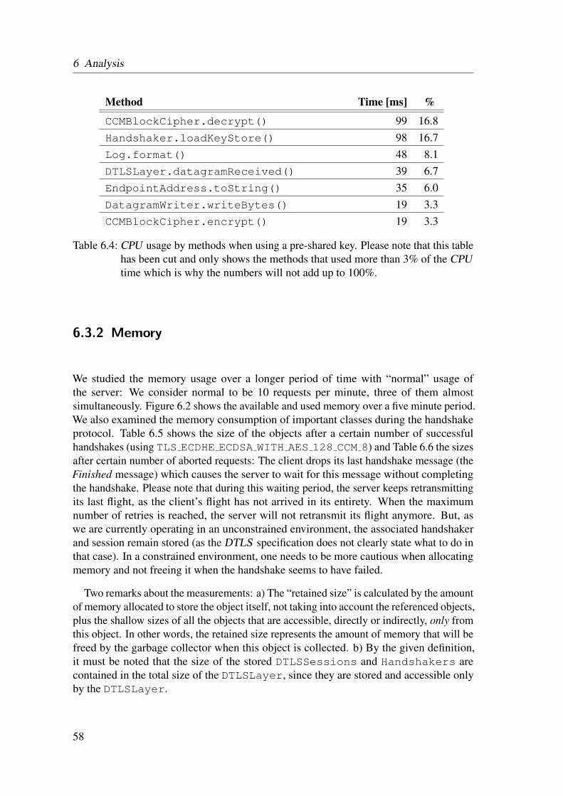
6 Analysis
Method Time [ms] %
CCMBlockCipher.decrypt() 99 16.8Handshaker.loadKeyStore() 98 16.7Log.format() 48 8.1DTLSLayer.datagramReceived() 39 6.7EndpointAddress.toString() 35 6.0DatagramWriter.writeBytes() 19 3.3CCMBlockCipher.encrypt() 19 3.3
Table 6.4: CPU usage by methods when using a pre-shared key. Please note that this tablehas been cut and only shows the methods that used more than 3% of the CPUtime which is why the numbers will not add up to 100%.
6.3.2 Memory
We studied the memory usage over a longer period of time with “normal” usage ofthe server: We consider normal to be 10 requests per minute, three of them almostsimultaneously. Figure 6.2 shows the available and used memory over a five minute period.We also examined the memory consumption of important classes during the handshakeprotocol. Table 6.5 shows the size of the objects after a certain number of successfulhandshakes (using TLS ECDHE ECDSA WITH AES 128 CCM 8) and Table 6.6 the sizesafter certain number of aborted requests: The client drops its last handshake message (theFinished message) which causes the server to wait for this message without completingthe handshake. Please note that during this waiting period, the server keeps retransmittingits last flight, as the client’s flight has not arrived in its entirety. When the maximumnumber of retries is reached, the server will not retransmit its flight anymore. But, aswe are currently operating in an unconstrained environment, the associated handshakerand session remain stored (as the DTLS specification does not clearly state what to do inthat case). In a constrained environment, one needs to be more cautious when allocatingmemory and not freeing it when the handshake seems to have failed.
Two remarks about the measurements: a) The “retained size” is calculated by the amountof memory allocated to store the object itself, not taking into account the referenced objects,plus the shallow sizes of all the objects that are accessible, directly or indirectly, only fromthis object. In other words, the retained size represents the amount of memory that will befreed by the garbage collector when this object is collected. b) By the given definition,it must be noted that the size of the stored DTLSSessions and Handshakers arecontained in the total size of the DTLSLayer, since they are stored and accessible onlyby the DTLSLayer.
58

6.3 Profiling
Figure 6.2: The memory usage over a five-minute period. The peaks mark the momentsbefore garbage collection occurs.
Initial 1 Request 2 Requests 5 Requests
DTLSSession 0 664 1328 3320Handshaker 0 0 0 0DTLSLayer 512 1304 2080 4408
Table 6.5: Retained size of objects (in bytes) after a certain number of successful requests.
6.3.3 Discussion
Let us first examine the CPU measurements: The data in Table 6.3 shows what could havebeen expected from the beginning: Using ECC for the key agreement protocol is veryresource-intensive and uses a lot of the CPU time. Additional, loading the certificate chainand private key, and parsing the peer’s certificate chain and verifying it takes up a lot ofCPU time as well. Thus, one of the conclusions we can draw from this data, regardingthe use of this protocol in constrained environments, is that we should use wheneveracceptable a PSK algorithm for key agreement, or an out-of-band public key validation,or both. The data in Table 6.4 confirms this assumption. When a pre-shared key is used tocalculate the Master Secret, the encryption is the defining factor for the CPU time, whichseems acceptable as it is the main security feature.
Another detection for future optimisation is that resources should be loaded lazily. TheloadKeyStore() method, which loads the certificate chain and the entity’s privatekey, is invoked at the initialisation of the handshaker but never used during the handshake
59

6 Analysis
Initial 1 Request 2 Requests 5 Requests
DTLSSession 0 360 720 1800Handshaker 0 6104 12208 30520DTLSLayer 512 7352 14176 34648
Table 6.6: Retained size of objects (in bytes) after a certain number of aborted requests.
protocol because the TLS PSK WITH AES 128 CCM 8 ciphersuite does not require anyauthentication. In an unconstrained environment, this is not really a consequence, butfor constrained environments this could be a crucial optimisation. Another remark aboutthe different CPU times of the encrypt() and decrypt() methods: This data couldsomehow imply that the decrypt() methods uses more CPU time or is invoked moreoften, but this is not the case. Both methods should use about the same CPU time, but sincethe server must first decrypt the client’s finished message, and only afterwards encrypts itsmessage, the first-time loading of the underlying Cipher instance must be the limitingfactor.
Now, let us go over the memory measurements. Figure 6.2 depicts a normal behaviour ofsuch applications: The used memory increases linearly until the garbage collector executesanother garbage collection round which brings the used memory back to the normal level.So, during normal execution no memory leak is apparent. This can be seen in Table6.5: After a successful client request, the memory needed by the DTLSLayer increasesroughly by the size of the DTLSSession which is stored while the connection is stillactive or resumable. The used Handshaker is deleted after finishing the handshakeand does not consume any memory. So far, no mechanism has been implemented thatremoves old sessions to free memory although they could still be used. Though, with asize of approximately 700 bytes, this does not seem to be a problem in an unconstrainedenvironment.
On the other hand, Table 6.6 shows a potential weak point of our implementation inan unconstrained environment but especially in a constrained environment: During thesemeasurements, the client did not send its last handshake message causing the server to waitfor this message indefinitely. Thus, the handshake cannot be completed and the associatedHandshaker remains stored in the DTLSLayer. So far, there is no mechanism todelete such failed Handshakers after a certain period of time, therefore the server’savailable memory could be overloaded with such an attack. For future implementations,this must be handled to prevent nodes with constrained memory from becoming vulnerableto such attacks.
60

7 Discussion
In this chapter, we will summarise the findings of the last chapters, state the current statusof our implementation, what has been achieved and what still needs to be done. Further,we will deliver insight into the problems we had during the implementation and testingphase.
7.1 Threat Model
In Chapter 3 we introduced nine potential security threats which must be considered whentrying to provide security for the IoT . Since DTLS is a security protocol that operatesat the application layer, four security threats located above this layer cannot be handledsolely by DTLS and remain a potential security risk: device cloning, substitution, privacythreat and extraction of security parameters. As mentioned, this part of physical securitythreats remain a problem that still needs reasonable countermeasures coupled with DTLS .So, what about the remaining five security threats?
Firmware ReplacementA thing secured exclusively by DTLS is not protected against firmware replace-ment attacks. If an attacker is able to exploit a firmware upgrade to influence theoperational behaviour of a thing, there is no use for encrypted communication andauthentication since the thing has been compromised at a higher level rendering thisendeavour useless.
EavesdroppingDTLS provides full protection against eavesdropping. This is true for our imple-mentation as long as the pre-shared key is not compromised and as long as theDiffie-Hellman assumption holds (which seems not to be at risk at the moment). Aneavesdropper who does not know the private Diffie-Hellman values or the pre-sharedsecret has no option to derive the Premaster Secret and therefore is unable to decryptthe protected application data.
Man-In-the-Middle AttackWhenever the server is successfully authenticated, the channel is secure againstman-in-the-middle attacks. Only completely anonymous sessions are inherentlyvulnerable to such attacks; but we do not negotiate ciphersuites that support anony-
61

7 Discussion
mous sessions. If the server is authenticated using a public key infrastructure or anout-of-band mechanism, an attacker has no possibility to forge the server’s Server-KeyExchange message which is signed with the appropriate private key. When aPSK key exchange algorithm is used that does not require the server to authenticateitself, the authentication has already taken place before the actual handshake occurs:By knowing the pre-shared key, which must have been distributed in a secure andconfidential way, both parties can be assured that there is no man-in-the-middleattack going on because an attacker would fail to forge the authentication tag in thecipher.
Denial-of-Service AttackDTLS is susceptible to a number of DoS attacks. While the introduction of statelesscookie exchange in the server’s HelloVerifyRequest message prevents DoS amplifi-cation attacks, and therefore protects constrained nodes, the server still remains avulnerable target. Although the cookie exchange protects the server from executingCPU -intensive computations, a large number of simultaneously initiated sessionscan still cause the server to become unavailable for its intended users.
Routing AttacksRouting attacks take place at the network layer where an attacker can manipulateroutes and the traffic over certain nodes. DTLS has no control over the path thepackets take in the network. So, DTLS is vulnerable to certain routing attacks likesinkhole and selective forwarding attacks, but is secure against spoofing or alteringof messages.
As we have noted before, DTLS alone will not prevent node capture attacks where anattacker captures a physically unprotected thing and tries to extract security parameters.So, what is the worst that could happen to a node secured with the current DTLS imple-mentation exposed to such an attack? Let us examine what kind sensitive data is stored ona single node:
Certificates and Private KeyThe certificate chain and corresponding private key must be stored on the node to beeasy accessible by DTLS . For Cf we used a password-protected Java keystore, butany other data structure is possible. Even if the certificates and keys are password-protected, preventing an intruder from extracting those is hard since the passworditself must be stored on the node itself. So, if the flash memory of a node can beaccessed, the password and therefore the certificates and keys can be extracted [16].The only protection against such attacks is some sort of certificate revocation list toinvalidate the certificate once it has been compromised [5].
Pre-Shared KeysThe pre-shared keys are currently stored directly in the Java code. So, if theattacker gets hold of the executable JAR file, he can easily extracts those values,compromising all connections where these keys will be or have been used. So, if an
62

7.2 Performance Optimisation
attacker is able to extract the pre-shared keys and if he has been eavesdropping pasthandshakes, he will be able to decrypt all encrypted messages afterwards; PSK doesnot provide Perfect Forward Secrecy (PFS) [12]. This is because one needs only thepre-shared key and the client’s and server’s random values (which are transmittedunsecured) to generate the Master Secret. Therefore, protecting the pre-shared keysfrom being extracted should be a high priority issue.
SessionsDuring a lifetime of a node, it will establish secured connections to various peers.Each time a handshake was successful, the node stores a session containing twosensitive values: the Master Secret and the session identifier. Having obtained thesevalues, an attacker can initiate future secured connections and impersonate this nodeusing these two values in a resuming handshake. Additionally, since the MasterSecret is compromised, all old conversations secured with it, can be decrypted. Howeasy it would be for an attacker to extract these values out of the memory of therunning program is hard to tell [5], but as it poses a potential security risk, thisshould be examined further in the future.
As we have seen, using a PSK key exchange algorithm has its advantages, especiallya simplified and faster handshake, but it is also a potential threat to security once a keyhas been compromised as it does not provide PFS . In contrast, using ephemeral keys asin ECDH key exchange guarantees PFS (as long as the Master Secret remains secured).Thus, for a more complex and time-consuming handshake, we gain this security feature.
7.2 Performance Optimisation
In Section 7.5 we gave several ideas for simple performance optimisations regardingmemory and CPU usage. And, as usual in software engineering, there would be lot ofadditional possibilities to achieve better performance. But, at the current stage of theimplementation, making this a high priority issue would be the wrong decision: Theimplementation has currently several untested features which makes it even harder torefactor the current code for optimisation reasons. Also, especially in a security system,a correct implementation should always be favoured over a fast (and maybe faulty)implementation. Currently, due to the lack of other implementations, we are too shorton experience about the stability and correctness of the implementation. Once we havegained more insight about this, optimisation can be considered. Additionally, Cf willundergo refactoring in the future which will result in necessary changes to the DTLSimplementation for integration purposes. This must also be solved prior to optimisation.
63

7 Discussion
7.3 Known Issues
In this section, we list the known issues with our current implementation. Some of themcan be seen as optional optimisations and others as required fixes as they contradictwith the specification; these have mainly been detected during the writing process whilerereading the specifications, but not during the testing phase. First, the optional changes:
• The DTLSLayer should be able to handle both secured and unsecured CoAPmessages. Currently, if the DTLSLayer receives an UDP datagram, it interprets itas a DTLS record and parses it accordingly to the DTLS message format. So, if anunsecured CoAP message is received, this will result in an error due to the differentmessage formats. This is not really a problem, since the CoAP specification definesthe coaps scheme and a separate port for secured connections. Thus, if a plainCoAP is received at this port, it is acceptable to discard it (because it should not besent to this port), but it would be a nice-to-have feature to handle this case as well.
• When a certificate chain is validated, the trusted certificates configured in thecacerts keystore file should be used as well. So far, we only load the truststorefile, which is configured in the Properties class, containing certain trustedcertificates of CAs. But the Java runtime environment contains a system-widekeystore cacerts with CA certificates which should also be utilised.
• When deployed in a real constrained network, self-signed certificates should notbe allowed anymore. For testing purposes—not everybody has a certificate signedby a commercial CA—we allow a peer to authenticate itself using a self-signedcertificate. Self-signed certificates can easily be manipulated and must not be usedfor real-life authentication.
• The cookie exchange during the handshake should be performed by the serverwithout generating any state. The stateless cookie exchange has been introduced toprevent DoS attacks. Currently, the server allocates already a new Handshakerand DTLSSession object when a ClientHello messages is received for the firsttime. But this should not be done until the client has replied with the correct cookieto protect itself from DoS attacks which try to consume as much memory of theserver as possible.
• To support as many named curves as possible when using ECDH key agreement,all recommended elliptic curves parameters should be implemented: There are25 named curves specified in [6]. Currently, only secp521r1, secp384r1,secp256r1, secp256k1, secp224r1 and secp224k1 are supported.
• Change the 2-byte identifier of the ciphersuite TLS ECDHE ECDSA WITH AES -128 CCM 8 once it is officially specified by IANA [40].
64
7.3 Known Issues
• CoAP defines two mandatory to implement ciphersuites which both are supportedin the current implementation. While the focus of other DTLS implementationsalso lies on these two ciphersuites, it would be advisable to implement others aswell. Especially, because so far only AEAD ciphers have been implemented whileblock ciphers are still missing.
Following, changes that need to be implemented to conform to the protocol specification:
• When the server sends its ephemeral ECDH public key, all types of elliptic curveparameters must be supported. Currently, only the use of named curves is imple-mented and although recommended by the specification, the two other types mustalso be supported: explicit prime and explicit char2.
• Whenever a ChangeCipherSpec message is received, it must be guaranteed that allprior handshake messages have been received. Right now, when a ChangeCipher-Spec message is received, it is processed and the current read state is updated. Butdue to message lost and reordering, it is possible that certain messages have not yetarrived and would be interpreted with the wrong read state. Of course, this can onlyhappen, when the peer’s flight does not fit into one datagram.
• The Internet-Draft [44] introduces the support for raw public keys in DTLS . Whilethe support for sending raw public keys and the handshake extension cert typeis implemented, an out-of-band public key validation mechanism, like DNS-basedAuthentication of Named Entities (DANE) [17] or pre-configured keys, is stillmissing.
• Multiple handshake messages may be placed in the same DTLS record, provided thatthere is room and that they are part of the same flight. Thus, there are two acceptableways to pack two DTLS messages into the same datagram: in the same record or inseparate records. Currently, only one way is supported: Each handshake message isput into a separate record. During the implementation phase, the specification wasmisinterpreted and this error was not detected during the testing phase either. Whatneeds to be changed is the parsing of the record layer while the sending can remainunchanged since it is not required that both ways must be supported for the sendingpart (only for the receiving).
• DTLS records contain a sequence number to provide replay protection. Sequencenumber verification can be performed using a sliding window procedure with awindows size of 32 or 64. The specification defines this feature to be recommendedbut not mandatory, nonetheless it should be implemented as soon as possible.
65

7 Discussion
7.4 Implementation Notes
In this section, we want to share a few advices and lessons we learnt during the imple-mentation and especially during the testing phase. They mainly consist of interpretationproblems of the different specifications.
• The first ClientHello (not containing the cookie), HelloVerifyRequest, and Change-CipherSpec messages are not included in the handshake messages hash used inthe verify data of the Finished message; the same is true for the handshakemessages used in the CertificateVerify message.
• The second Finished message must also contain the first Finished message in thehandshake hash to compute the verify data.
• Although the verify data can have a variable length in the Finished message,there is no length field prepended to it during the serialisation. The length is definedby the used ciphersuite and is normally 12 octets.
• The Finished MAC must be computed as if each handshake message had beenreceived in a single fragment.
• There are several hello extension types, so it is possible that not each one is supportedby an implementation. As long as a ciphersuite is negotiated that does not needthis specific extension, it is no problem to continue the handshake. But, oneneeds to make sure that the unknown extension is still included in the handshakemessages hash in the Finished message, otherwise the verify data will notmatch, resulting in an aborted handshake.
• Although DTLS modified the ClientHello message format in such a way that theextensions field was dropped, the client must be able to send extensions in itshello message; this field must have been forgotten.
• A variable-length vector in the message format definition must always be precededwith the actual length when encoded, even if the length is clear from the givencontext. For example, when receiving the ServerHello message containing thecertificate type extension, we know that the server’s supported certificate typescontains exactly one element; nevertheless we need to add a length field in front ofit, since the extension data is defined as a variable-length vector:
opaque extension_data<0..2ˆ16-1>;
• When using an AEAD cipher, we need to generate additional authentication data,which is defined as follows:
additional_data = seq_num + TLSCompressed.type +TLSCompressed.version + TLSCompressed.length;
66

7.4 Implementation Notes
The seq num is defined for DTLS as the concatenation of the 16-bit epoch and the48-bit sequence number of the record header. Additional, the explicit nonce, whichmust be prepended to the ciphertext, has the same value.
• The node that transmits the last flight of the handshake (the server in an ordinaryhandshake or the client in a resumed handshake) must respond to a retransmit ofthe peer’s last flight with a retransmit of the last flight. But it must not retransmitits last flight because of an expired timer; there is no timer set in this state of thehandshake.
• When a connection is established by resuming a session, new ClientHello.-random and ServerHello.random values are hashed with the master secretof the session which has been generated in the first full handshake.
• Whenever a digitally-signed element is encoded, the used signature and hash algo-rithm must be included as well. This is the case for the CertificateVerify message.
• The security parameter values for the ciphersuites TLS PSK WITH AES 128 -CCM 8 and TLS ECDHE ECDSA WITH AES 128 CCM 8 are:
– PRFAlgorithm: tls prf sha256– BulkCipherAlgorithm: aes– CipherType: aead– EncKeyLength: 16 octets– BlockLength: 16 octets (not relevant for AEAD ciphers)– FixedIvLength: 4 octets– RecordIvLength: 8 octets– MACAlgorithm: null– MACLength: 0 octets– MACKeyLength: 0 octets (no MAC because of the use of AEAD ciphers)– CompressionMethod: null
67

7 Discussion
7.5 Optimising the Current DTLS Implementation
Our current implementation of DTLS for Cf was not specialised for use in constrainedenvironments—and probably will never be since it is implemented in Java. Still, we wouldlike to point out a few potential implementation optimisations.
7.5.1 Memory Usage
In our implementation, we utilise several Maps and Collections to store associatedinformation (e.g., DTLSSessions) or to provide buffering (e.g., for Handshake-Messages). These data structures grow according to the number of elements until theavailable memory is used up. This can be very dangerous for constrained nodes becauseit makes them vulnerable to DoS attacks that try to exhaust the victim’s resources. Onereasonable optimisation would be to allow only a fixed number of slots for each bufferinstead of dynamically allocating more memory whenever new items must be buffered.This approach would guarantee an upper bound for used memory, but at the same time itcreates the risk of limiting availability: Requests may not be processed due to missingslots. Furthermore, an algorithm that removes old DTLSSessions could help savingmemory. But it is important to note that deleting a DTLSSession forces the parties toexecute the full handshake instead of the abbreviated handshake to establish a new secureconnection. The trade-off between low memory usage and CPU -intensive operations mustbe evaluated carefully.
7.5.2 CPU Usage
The CPU usage is mainly bound by the cryptographic operations that must be executedduring the handshake. Whenever possible, as described, the implementation utilises thebuilt-in functionality of Java. Since it is widely used and tested, performance shouldbe hard to be optimised: A handmade implementation may perform slightly better thanone of Java, but this introduces the risk of bugs due to a faulty implementation whichis not worth taking for a potential slight optimisation. One optimisation could be re-alised when negotiating the ciphersuite. The server should not choose the first supportedciphersuite proposed by the client, but the one which has the least CPU -consumingoperations while guaranteeing the required security level. So, for the current implemen-tation, the server should always chose the TLS PSK WITH AES 128 CCM 8 over theTLS ECDHE ECDSA WITH AES 128 CCM 8 ciphersuite—as long as the client proposesboth—disregarding the client’s preferences.
68

7.6 Future Implementations
7.6 Future Implementations
As we have mentioned, the current implementation is not suited for constrained environ-ments. Even if we would optimise the implementation and use a JVM designed specificallyfor resource-constrained nodes [2], the memory- and code-footprint will probably still betoo large. Therefore, the next step will be to implement DTLS in a low-level program-ming language, most likely in C. During the implementation of DTLS for Cf , we gainedexperience about the complexity of the different parts that make up the DTLS protocoland we evaluate them on their potential impact on a low-level implementation:
SerialisationAlthough quite complex in the understanding, serialisation should not be difficultand costly to be implemented. Especially, since the handling of low-level datastructures such as byte arrays is more intuitive and simpler than in Java, and thespecified message formats are already in a C-like structure.
DTLS State MachineThe DTLS state machine, which controls the handshake message flow and handlestimeouts and retransmissions (in Cf called the DTLSLayer), is one of the core piecesin DTLS . As it must provide lots of different functionality, its code-footprint willpotentially be one of the largest in the implementation.
EncryptionThe mandatory AES-CCM encryption algorithm has been implemented by us in Java.This code could be ported to C, resulting already in an acceptable code-footprint.Also, there exist several implementations for the efficient use in resource-constrainedenvironments [18, 34].
Fragmentation & RetransmissionsAs we have discussed in Section 3.5, CoAP could be used to transfer the DTLShandshake messages instead of the DTLS protocol. Like this, support for fragmen-tation and retransmission could be left out, as CoAP provides this already. In Cf ,the implementation of fragmentation is only about 200 lines of code, which willlook similar in the C code. So, this is not a strong argument in favour of usingCoAP to transfer the DTLS messages. For retransmissions this looks a little bitdifferent: Implementing retransmission in DTLS requires primarily a data structurethat holds the whole flight that needs to be retransmissioned once the timer expires.Therefore, memory-wise it would be wise to let CoAP handle this directly, insteadof implementing a very similar mechanism again for DTLS .
Let us also take a look at some estimations about the needed buffer sizes to successfullyexecute a handshake: Due to reordering, we need buffers to store handshake messages, toprocess them in the right order and to compute the handshake messages hash correctly(used in the Finished message). So, we cannot handle everything on-the-fly. In a worst-case scenario, the client needs to buffer around 1 kB of handshake messages data: This can
69

7 Discussion
happen, when mutual authentication is required and the ServerHello message is lost. Untilthe message is retransmitted, the client must store the Certificate (containing the full X.509certificate), ServerKeyExchange, and CertificateRequest messages. At the same time, theclient must also provide buffers for the messages that might need to be retransmitted,and store intermediary results that are needed at a later point in the handshake (e.g., therandom values, the digest of the handshake messages or the server’s public and ephemeralpublic key). So, roughly, 2-3 kB of data must be stored during a handshake.
This could be reduced when reordering is handled in another way: When we alwaysdiscard a received message if it is not the next one expected, we do not need any buffers tostore the handshake messages that arrived out of order. Additionally, for retransmissionswe do not need to store the whole flight, but just the important information, and re-generatethe flight each time the timer expires. So, by only storing the intermediary results andnot providing any buffers, we can largely reduce the expected amount of data to bestored during a handshake at the cost of a potential higher handshake duration (due to theincreased number of retransmissions) and higher CPU usage.
This changes again, when fragmentation must be handled. In this case, we must provideat least some buffers: Even if we still discard each message that arrives out of order, weneed to store the part of the fragmented handshake message that has already been receiveduntil all fragments have arrived because parsing the fragments on-the-fly would onlycomplicate the problem: For example, parsing the first 200 bytes of a X.509 certificatewould be of no advantage, as the parsed part (and the parts that could not yet be parsedcompletely) must be stored somewhere as well, and reassembling parts of a certificate isfar more complicated than parsing it all at once. Thus, as a certificate can be about 1 kB insize, we must at least be able to buffer this size of fragmented handshake messages.
70

8 Conclusion
The goal of this thesis was to evaluate the planned security model for the ConstrainedApplication Protocol (CoAP) . We gave an overview of the security threats that existduring the different phases of the lifetime of a thing (i.e., manufacturing, installation andcommissioning, and operational) and outlined the measurements to ensure security duringthese phases.
We presented a roadmap that outlines ideas to make Datagram Transport Layer Security(DTLS) more friendly for constrained environments. Among other ideas, Hartke &Bergmann propose a stateless header compression algorithm that can help reducing theheader size of DTLS messages considerably. This approach looks very promising asthe DTLS headers produce unnecessary overhead with its fixed-length header fields.Also, reducing the complexity of DTLS by simplifying the protocol, providing suitableciphersuites, or supporting raw public keys will be a crucial optimisation for DTLS tobecome a valuable technique for securing a constrained environment in the future.
As a first step towards a secured CoAP , we implemented DTLS for Californium (Cf) ,a CoAP framework written in Java and developed for the use in unconstrained environ-ments. The basic functionalities of the implementation have been successfully testedfor interoperability with three other DTLS implementations, while fragmentation andraw public keys remain untested due to current lack of other implementations supportingthese. A full handshake increases the average round-trip time of about 40ms by 130 up to230ms, depending on the chosen ciphersuite. Once a session has been established betweentwo nodes, the overhead to provide security is just 5ms. Based on threat modelling, thisimplementation secures a connection between two nodes during the operational phase byproviding confidentiality and message integrity, and therefore prevents eavesdropping,man-in-the-middle, and denial-of-service attacks. Protection against physical attacks, suchas node capture, and security bootstrapping remain unresolved for this approach, butpotential procedures have been described to achieve both.
Based on the gained experience during the design, implementation, and testing phase, wegave a summary about the potential pitfalls when implementing DTLS , and estimated thecode and memory complexity of future DTLS implementations in low-level programminglanguages.
71


Bibliography
[1] ANSI X9.62-2005. Public Key Cryptography for the Financial Services Industry: TheElliptic Curve Digital Signature Algorithm (ECDSA). American National StandardsInstitute, Nov. 2005.
[2] F. Aslam, C. Schindelhauer, G. Ernst, D. Spyra, J. Meyer, and M. Zalloom. Introduc-ing TakaTuka – A Java Virtual Machine for Motes. In Proceedings of the 6th ACMConference on Embedded Network Sensor Systems (SenSys 2008), New York, USA,Nov. 2008.
[3] L. Atzori, A. Iera, and G. Morabito. The Internet of Things: A survey. ComputerNetworks, 54(15):2787–2805, Aug. 2010.
[4] T. Aura. Cryptographically Generated Addresses (CGA). RFC 3972 (ProposedStandard), Mar. 2005. Updated by RFCs 4581, 4982.
[5] A. Becher, Z. Benenson, and M. Dornseif. Tampering with Motes: Real-WorldPhysical Attacks on Wireless Sensor Networks, volume 3934 of Lecture Notes inComputer Science, pages 104–118. Springer Berlin / Heidelberg, 2006.
[6] S. Blake-Wilson, N. Bolyard, V. Gupta, C. Hawk, and B. Moeller. Elliptic CurveCryptography (ECC) Cipher Suites for Transport Layer Security (TLS). RFC 4492(Informational), May 2006. Updated by RFC 5246.
[7] C. Bormann and Z. Shelby. Blockwise transfers in CoAP. draft-ietf-core-block-09,Aug. 2012.
[8] W. Colitti, K. Steenhaut, N. D. Caro, B. Buta, and V. Dobrota. REST EnabledWireless Sensor Networks for Seamless Integration with Web Applications. InProceedings of the 8th IEEE International Conference on Mobile Ad-hoc and SensorSystems (MASS 2011), Valencia, Spain, Oct. 2011.
[9] D. Cooper, S. Santesson, S. Farrell, S. Boeyen, R. Housley, and W. Polk. InternetX.509 Public Key Infrastructure Certificate and Certificate Revocation List (CRL)Profile. RFC 5280 (Proposed Standard), May 2008.
[10] T. Dierks and E. Rescorla. The Transport Layer Security (TLS) Protocol Version 1.2.RFC 5246 (Proposed Standard), Aug. 2008. Updated by RFCs 5746, 5878, 6176.
73

Bibliography
[11] O. Dubuisson and P. Fouquart. ASN.1: Communication Between HeterogeneousSystems. Morgan Kaufmann, San Francisco, CA, USA, 2001.
[12] P. Eronen and H. Tschofenig. Pre-Shared Key Ciphersuites for Transport LayerSecurity (TLS). RFC 4279 (Proposed Standard), Dec. 2005.
[13] O. Garcia-Morchon, S. Keoh, S. Kumar, R. Hummen, and R. Struik. SecurityConsiderations in the IP-based Internet of Things. draft-garcia-core-security-04, Mar.2012.
[14] D. Giusto, A. Iera, G. Morabito, L. Atzori, C. M. Medaglia, and A. Serbanati. AnOverview of Privacy and Security Issues in the Internet of Things. In The Internet ofThings, pages 389–395. Springer New York, 2010.
[15] K. Hartke and O. Bergmann. Datagram Transport Layer Security in ConstrainedEnvironments. draft-hartke-core-codtls-02, July 2012.
[16] C. Hartung, J. Balsalle, and R. Han. Node Compromise in Sensor Networks: TheNeed for Secure Systems. Technical Report CU-CS-990-05, Department of ComputerScience, University of Colorado, Boulder, Jan. 2005.
[17] P. Hoffman and J. Schlyter. The DNS-Based Authentication of Named Entities(DANE) Transport Layer Security (TLS) Protocol: TLSA. RFC 6698 (ProposedStandard), Aug. 2012.
[18] L. Huai, X. Zou, Z. Liu, and Y. Han. An Energy-Efficient AES-CCM Implementationfor IEEE802.15.4 Wireless Sensor Networks. In Proceedings of the InternationalConference on Networks Security, Wireless Communications and Trusted Computing(NSWCTC 2009), Wuhan, Hubei China, Apr. 2009.
[19] J. Hui and P. Thubert. Compression Format for IPv6 Datagrams over IEEE 802.15.4-Based Networks. RFC 6282 (Proposed Standard), Sept. 2011.
[20] S. Kent. IP Encapsulating Security Payload (ESP). RFC 4303 (Proposed Standard),Dec. 2005.
[21] M. Kovatsch, S. Duquennoy, and A. Dunkels. A Low-Power CoAP for Contiki. InProceedings of the 8th IEEE International Conference on Mobile Ad-hoc and SensorSystems (MASS 2011), Valencia, Spain, Oct. 2011.
[22] H. Krawczyk, M. Bellare, and R. Canetti. HMAC: Keyed-Hashing for MessageAuthentication. RFC 2104 (Informational), Feb. 1997. Updated by RFC 6151.
[23] K. Kuladinithi, O. Bergmann, T. Potsch, M. Becker, and C. Gorg. Implementationof CoAP and its Application in Transport Logistics. In Proceedings of the 10thInternational Conference on Information Processing in Sensor Networks (IPSN2011), Chicago, USA, Apr. 2011.
74

Bibliography
[24] C. Lerche, K. Hartke, and M. Kovatsch. Industry Adoption of the Internet of Things:A Constrained Application Protocol Survey. In Proceedings of the 7th InternationalWorkshop on Service Oriented Architectures in Converging Networked Environments(SOCNE 2012), Krakow, Poland, Sept. 2012.
[25] D. McGrew and D. Bailey. AES-CCM Cipher Suites for Transport Layer Security(TLS). RFC 6655 (Proposed Standard), July 2012.
[26] G. Montenegro, N. Kushalnagar, J. Hui, and D. Culler. Transmission of IPv6 Packetsover IEEE 802.15.4 Networks. RFC 4944 (Proposed Standard), Sept. 2007. Updatedby RFC 6282.
[27] N. Modadugu and E. Rescorla. The Design and Implementation of Datagram TLS.In Proceedings of the Network and Distributed System Security Symposium (NDSS2004), San Diego, USA, Feb. 2004.
[28] S. Park, K. Kim, W. Haddad, S. Chakrabarti, and J. Laganier. IPv6 over Low PowerWPAN Security Analysis. draft-daniel-6lowpan-security-analysis-05, Mar. 2011.
[29] D. Pauli and D. I. Obersteg. Californium. Lab Project, D-INFK, ETH Zurich, Dec.2011.
[30] N. R. Potlapally, S. Ravi, A. Raghunathan, and N. K. Jha. Analyzing the EnergyConsumption of Security Protocols. In Proceedings of the 2003 InternationalSymposium on Low Power Electronics and Design (ISLPED 2003), Seoul, Korea,Aug. 2003.
[31] S. Raza, S. Duquennoy, J. Hoglund, U. Roedig, and T. Voigt. Secure Communicationfor the Internet of Things - A Comparison of Link-Layer Security and IPsec for6LoWPAN. Security and Communication Networks, Jan. 2012.
[32] S. Raza, D. Trabalza, and T. Voigt. 6LoWPAN Compressed DTLS for CoAP. InProceedings of the 8th IEEE International Conference on Distributed Computing inSensor Systems (DCOSS 2012), Hangzhou, China, May 2012.
[33] E. Rescorla and N. Modadugu. Datagram Transport Layer Security Version 1.2. RFC6347 (Proposed Standard), Jan. 2012.
[34] A. Samiah, A. Aziz, and N. Ikram. An Efficient Software Implementation of AES-CCM for IEEE 802.11i Wireless Standard. In Proceedings of the 31st AnnualInternational Computer Software and Applications Conference (COMPSAC 2007),Beijing, China, July 2007.
[35] B. Sarikaya, Y. Ohba, R. Moskowitz, Z. Cao, and R. Cragie. Framework for SecurelySetting Up Smart Objects. draft-sarikaya-solace-setup-framework-00, Sept. 2012.
75

Bibliography
[36] B. Sarikaya, Y. Ohba, R. Moskowitz, Z. Cao, and R. Cragie. Security BootstrappingSolution for Resource-Constrained Devices. draft-sarikaya-core-sbootstrapping-05,July 2012.
[37] Z. Shelby, K. Hartke, C. Bormann, and B. Frank. Constrained Application Protocol(CoAP). draft-ietf-core-coap-12, Oct. 2012.
[38] Standards for Efficient Cryptography Group (SECG). SEC 2: Recommended EllipticCurve Domain Parameters, Sept. 2000.
[39] Standards for Efficient Cryptography Group (SECG). SEC 1: Elliptic Curve Cryp-tography, May 2009.
[40] The Internet Assigned Numbers Authority (IANA). Transport Layer Security (TLS)Parameters. Cipher Suite Registry 18 July 2012.
[41] R. H. Weber. Internet of Things – New Security and Privacy Challenges. ComputerLaw Security Review, 26(1):23–30, Jan. 2010.
[42] D. Whiting, R. Housley, and N. Ferguson. Counter with CBC-MAC (CCM). RFC3610 (Informational), Sept. 2003.
[43] T. Winter, P. Thubert, A. Brandt, J. Hui, R. Kelsey, P. Levis, K. Pister, R. Struik,J. Vasseur, and R. Alexander. RPL: IPv6 Routing Protocol for Low-Power and LossyNetworks. RFC 6550 (Proposed Standard), Mar. 2012.
[44] P. Wouters, J. Gilmore, S. Weiler, T. Kivinen, and H. Tschofenig. Out-of-BandPublic Key Validation for Transport Layer Security. draft-ietf-tls-oob-pubkey-04,July 2012.
76

A Handshake Protocol
This chapter gives a detailed view about the DTLS handshake protocol. Following, a listof concepts used during the handshake that need explanation:
Pseudorandom Function (PRF)A Pseudorandom Function takes as input a secret, a seed, and an identifying labeland produces an output of arbitrary length. It is mainly used to generate keyingmaterial.
Premaster SecretThe Premaster Secret is a shared secret between two communicating peers. Itsderivation depends upon the negotiated key exchange algorithm: It can be prede-fined and already shared between the two parties or it can be generated during thehandshake protocol (e.g., using Diffie-Hellman). It can be of arbitrary length.
Master SecretThe Master Secret is a 48-byte secret shared between the two peers in the connection.It is generated using the Premaster Secret, a 32-byte random value provided byeach peer and a PRF . This step is required because the Premaster Secret mightnot provide enough entropy to derive the keys used for encryption and messageauthentication.
Connection StatesA Connection State specifies a compression, encryption and MAC algorithm, andthe corresponding keys. There are always four connection states outstanding: Thecurrent read and write state and the pending read and write state. All records areprocessed under the current read and write states. The handshake protocol is usedto set the pending state and the ChangeCipherSpec can make either of the pendingstates current: When a peer sends a ChangeCipherSpec it will make its pendingwrite state the current, meaning that outgoing records are now processed by the newstate. Receiving such a ChangeCipherSpec makes the pending read state the currentone.
A.1 Full Handshake
Figure A.1 illustrates the most complex type of the DTLS handshake protocol containingall possible handshake messages: ECDH Key Exchange with mutual authentication. Thedotted arrows indicate the messages that can be omitted by protocol definition; if left out,
77

A Handshake Protocol
Figure A.1: Message flights for a full DTLS handshake using ECDH key agreement andmutual authentication.
78

A.1 Full Handshake
neither the client nor the server will be authenticated at the end of the handshake. Theonly difference between the DTLS and the TLS handshake protocol is the message sent atFlight 2, the HelloVerifyRequest to prevent DoS attacks.
Please note that the handshake for Pre-Shared Key ciphersuites is a simplified versionof the depicted protocol, omitting the mutual authentication (ServerCertificate, Certificate-Request, ClientCertificate and CertificateVerify) and the ServerKeyExchange is excluded aswell. The Premaster Secret is derived by the identity of the Pre-Shared Key provided in theClientKeyExchange making the ServerKeyExchange irrelevant. The following listing willprovide explanations for each handshake message sent in a full DTLS handshake with usedciphersuite TLS ECDHE ECDSA WITH AES 128 CCM 8 and mutual authentication.
ClientHello 1The ClientHello message initiates a full handshake with a server. The client providestherein the security parameters it wants to run the handshake upon (i.e., DTLSversion, preferred ciphersuites, compression methods and several extensions). Addi-tionally, it provides a 32-byte random value which will be used in a later step of theprotocol to compute the Premaster Secret. In the first version of this message, theCookie field will be empty.
HelloVerifyRequestThe HelloVerifyRequest has been added by the DTLS specification as a DoS coun-termeasure [33]. There are particular two attacks that can be prevented with thistechnique: a) An attacker can cause the server to allocate state and potentiallyperform expensive cryptographic operations by transmitting a series of handshakeinitiation requests. b) An attacker can use the server as an amplifier by impersonat-ing the victim, resulting in the server flooding the victim with possible quite largemessages (e.g., ServerCertificate).
The HelloVerifyRequest contains a stateless cookie which is sent back to the client,forcing the client to be able to receive the cookie which makes DoS attacks withforged addresses hard.
ClientHello 2This ClientHello is identical to the first one sent, except for the added cookie takenfrom the HelloVerifyRequest.
ServerHelloThe ServerHello message is used by the server to notify the client about the negoti-ated security parameters under which the handshake will be executed (i.e., DTLSversion, ciphersuite and compression method). Additionally, the server provides a32-byte random value, also used later for calculating the Premaster Secret.
ServerCertificateThis message contains the server’s certificate chain ultimately signed by a certificateauthority. The first certificate in this chain contains the server’s static ECDH -capablepublic key and is signed with the ECDSA [6]. Upon receiving this message, the
79

A Handshake Protocol
client validates the certificate chain and extracts the server’s public key which willbe used to verify the ServerKeyExchange message.
ServerKeyExchangeThe ServerKeyExchange message is used to convey the server’s ephemeral ECDHpublic key to the client and the used elliptic curve domain parameters. The messageis signed with the private key corresponding to the public key sent in the Server-Certificate message. Upon receipt, the client verifies the signature and extracts theserver’s ephemeral public key and the elliptic curve domain parameters.
For a description about the Elliptic Curve Cryptography (ECC) please refer toAppendix B.
CertificateRequestThis message is sent whenever a non-anonymous server requires the client toauthenticate itself as well. It specifies a list of certificate types that the clientmay offer, a list of hash/signature algorithms the server is able to verify and list ofacceptable CAs . Only when this message is sent by the server, mutual authenticationcan be achieved.
ServerHelloDoneThe ServerHelloDone message indicates that the server is done sending messages tosupport the key exchange. It is needed because otherwise the client cannot be sureif the server’s flight is finished, because the second to last message defined in theprotocol (CertificateRequest) is not mandatory to be sent by the server.
ClientCertificateIf required by the server (by sending the CertificateRequest message), the clientneeds to send its certificate chain to the server to convey its static public key. Theserver validates the certificate chain and extracts the client’s public key.
ClientKeyExchangeThis message is sent in all key exchange algorithms. In this mode (ECDHE ECDSA)it contains the client’s ephemeral ECDH public key which it created correspondingto the parameter it received from the server in the ServerKeyExchange message.Upon receipt, the server extracts the client’s ephemeral key. Now, after havingexchanged their public key of the ECDH key pair, the client and the server can nowrun the ECDH key agreement protocol (described in Appendix B) to obtain thePremaster secret.
CertificateVerifyThis message is only sent following a ClientCertificate that has signing capability.The meaning for this message is to prove that the client really possesses the privatekey corresponding to the public key in the ClientCertificate message. The clientcomputes the hash over all handshake messages sent or received so far and computes
80

A.1 Full Handshake
the signature of it using its private key corresponding to the public key in the Client-Certificate. The server verifies the signature using the client’s public key received inthe ClientCertificate message.
ChangeCipherSpec (Client)After having computed the Master Secret the client signals that each messagereceived after this one will be secured with the negotiated security parameters.
Finished (Client)The Finished message is the first one protected with the newly negotiated securityparameters. The client hashes all previous sent or received handshake messages(excluding the first ClientHello, HelloVerifyRequest and ChangeCipherSpec) andgenerates the verify data by applying it to the Pseudorandom Function (PRF) .The server validates the client’s verify data.
ChangeCipherSpec (Server)After having the client’s Finished message validated, the server sends its ChangeCi-pherSpec with the same semantics as the client’s. Therefore, the pending write stateis copied to the current write state.
Finished (Server)The server’s Finished message contains the verify data which is computed thesame way as before, but the hash of the handshake messages also contains the client’sFinished message. This is the server’s first message protected with the negotiatedsecurity parameters, as the message directly follows its ChangeCipherSpec message.
Once a side has sent its Finished message and received and validated the peer’sFinished message, it may begin to send and receive application data over the con-nection.
For further details please refer to the specifications of ECC [6], TLS [10] and DTLS [33].
81

A Handshake Protocol
A.2 Abbreviated Handshake
An abbreviated handshake can be executed when the client and server decide to resume aprevious session. The message flow for this scenario is illustrated in Figure A.2. It canonly be executed when the two peers have successfully finished a full handshake in thepast, thus, having stored a session containing the session identifier and the Master Secretgenerated in the full handshake.
The Client sends a ClientHello using the session identifier of the session to be resumed.The server checks its session cache for a match. If a match is found, and the server is willingto re-establish the connection under the specified session state, it will send a ServerHellowith the same session identifier value. The fresh keys are generated from the existingMaster Secret and the newly exchanged random values. After the ChangeCipherSpecmessages, the connection will be secured with the fresh keys and the security parametersnegotiated during the full handshake. If the server does not find a match in the sessioncache, it generates a new session identifier and initiates a full handshake.
Figure A.2: Message flights for an abbreviated DTLS handshake.
82

B Elliptic Curve Cryptography
Elliptic Curve Cryptography (ECC) represents an alternative approach to public-keycryptography based on the algebraic structure of elliptic curves over finite fields specifiedby the Standards for Efficient Cryptography Group (SECG) [39]. ECC involves threeschemes:• Signature schemes,• encryption and key transport schemes, and• key agreement schemes.
Since the implemented ciphersuites only make use of ECC as a key exchange algorithm,we elaborate on the signature schemes and key agreement schemes only.
B.1 ECC-Based Key Exchange Algorithms
There are several key exchange algorithms proposed in RFC 4492 to compute the DTLSPremaster Secret. The one we are interested in is called ECDHE ECDSA: ephemeralECDH with ECDSA signatures [6]. The server and client exchange their ephemeralECDH public keys which both have been generated on the same negotiated elliptic curve.The server’s parameters must be signed with ECDSA using the private key correspondingto the public key in the server’s certificate (see Appendix A). Both client and serverperform the key agreement operation and use the result as the premaster secret.
B.2 Key Agreement Scheme
The Elliptic Curve Diffie-Hellman scheme is a key agreement scheme based on ECCwhich allows two entities to establish a shared secret over an insecure channel [39]. Bothneed an elliptic curve public-private key pair over a specified elliptic curve. This sharedsecret can be used to derive the Master Secret which can then be used for a symmetric keycipher. The algorithm consists of three steps:
Scheme SetupBoth parties need to establish the elliptic curve domain parametersT = (p,a,b,G,n,h) [39]. This is done in our implementation using the ServerKey-Exchange message which contains the named curve field: One value out of apredefined set of elliptic curve domain parameters.
83

B Elliptic Curve Cryptography
Key DeploymentThe client and the server both generate an elliptic curve key pair (dc,Qc), and(ds,Qs) respectively, with the negotiated elliptic curve domain parameters T . Theynow need the exchange their private keys Qc and Qs. This is done in the handshakeprotocol using the ClientKeyExchange and the ServerKeyExchange message.
Key Agreement OperationTo derive the shared secret, the client computes (xk,yk) = dcQs and the server(xk,yk) = dsQc. The shared secret is now xk, the x-coordinate of the computed point.
B.3 Signature Scheme
ECDSA is a variation of the Digital Signature Algorithm (DSA) that uses ECC . Thedata to be signed or verified is hashed and the result is run directly through the ECDSAalgorithm with no additional hashing. SHA-1 is used as the default hash function with adigest size of 160 bits. The ECDSA algorithm is performed according to ANSI X9.62 [1].
B.4 Advantages
There is a certain reason why the CoAP draft requires one of the two mandatory cipher-suites to use ECC : Compared to the commonly used cryptosystems (e.g., RSA), ECCcan use smaller key sizes to achieve the same level of security. Table B.1 [6] showsthe significant smaller key sizes that can be used by ECC which results in savings forpower, memory (i.e., storing of the keys), bandwidth (i.e., smaller ServerKeyExchangeand ClientKeyExchange messages) and computational cost that make ECC attractive forconstrained environments [6].
Symmetric ECC DH/DSA/RSA
80 163 1024112 233 2048128 283 3072192 409 7680256 571 15360
Table B.1: Comparable key sizes (in bits) for different cryptosystems.
84

C Keytool and OpenSSL
This chapter illustrates how to generate a certificate chain signed by a trusted authorityusing the keytool and openssl commands. We will create a certificate chain asdepicted in Figure C.1: There will be a certificate with the alias end that contains theentity’s public key to which a corresponding private key exists. This certificate will besigned by an intermediate CA named inter which is signed by a trusted CA with the aliasroot that completes the chain of trust. The end and inter certificate can then be sent toother parties (which trust the root CA as well) to authenticate itself.
Figure C.1: Example for a signed certificate chain. On top the trusted root certificateauthority.
85

C Keytool and OpenSSL
Generate the Private Key of the CAWe generate private keys for both root and inter in openssl since keytool isnot capable of signing Certificate Signing Requests (CSRs) .
openssl ecparam -name secp521r1 -genkey -out root.key
openssl ecparam -name secp521r1 -genkey -out inter.key
Generate Self-Signed Root CertificateThe trusted root CA signs its certificate with its own private key (root.key).
openssl req -new -key root.key -x509 -days 365 -out root.crt
This gives us a self-signed X.509 certificate (root.crt) which is valid for 365days.
Generate CSR for Intermediate CA
openssl req -new -key inter.key -out inter.csr
This creates a CSR (inter.csr) which can now be issued to the root CA to besigned.
Sign the CSR with the Private Key of the Root CA
openssl x509 -req -in inter.csr -CA root.crt -CAkey root.key -outinter.crt -days 365 -CAcreateserial
The Intermediate CA has now a certificate which is signed by the root CA . Naturally,in a real-world setup, this CSR would be signed by a commercial CA (such asThawte or VeriSign) that is trusted already by many devices.
Generate Key Pair for End Certificate
keytool -genkeypair -alias end -keyalg EC -keystore keyStore.jks-sigalg SHA1withECDSA -validity 365
This generates an ECC key Pair which is stored in the keyStore.jks file.
Generate CSR for End CertificateWe create now a CSR which contains the public key which can then be signed bythe intermediate CA .
keytool -certreq -alias end -keystore keyStore.jks -file end.csr
86

Sign the CSR with the Private Key of the Intermediate CA
openssl x509 -req -in end.csr -CA inter.crt -CAkey inter.key -outend.crt -days 365 -CAcreateserial
We now have an end certificate (end.crt) which is signed by the intermediateCA .
Add the Root Certificate to the Trusted CertificatesSince the Root certificate is a self-signed certificate, there is no chain of trust whichcan be invoked, because every entity can sign its own certificate. Therefore, weneed to add the certificate to the trusted certificates. For this use, there exists akeystore file named cacerts, which resides in the security properties directory ofJava. It comes with several root CA certificates already installed (such as Thawte orVeriSign) and can be configured by the system administrator.
keytool -importcert -alias californium -file root.crt -keystorejava.home/lib/security/cacerts
Now, we need other parties to trust our root certificate as well, otherwise theywill not be able to validate our certificate chain because of the missing trust inthe root. Therefore, we add our root certificate to a truststore which must thenbe delivered securely to remote parties. By importing our root certificates to theirtrusted certificates, the chain of trust can be established during the handshakeprotocol.
keytool -importcert -alias root -file root.crt -keystoretrustStore.jks
Import the Certificate Chain into the KeystoreFirst, we need to import the intermediate certificate into the keystore because thechain of trust relies on this certificate such that the end certificate can be imported(and trusted) afterwards.
keytool -importcert -alias inter -file inter.crt -keystorekeyStore.jks -trustcacerts
The -trustcacerts parameter specifies that additional certificates are consid-ered for the chain of trust, namely the certificates in the file cacerts, in which weadded the root certificate.
keytool -importcert -alias end -file end.crt -keystore keyStore.jks
87

C Keytool and OpenSSL
List the Certificates
keytool -list -v -keystore keyStore.jks
This command shows us the details of the created keystore, see Listing C.1 forthe output. The keystore contains a private key and a certificate containing thecorresponding public key. Additionally, there is a certificate chain with a trustedroot certificate that signs the intermediate one which signs the end certificate.
Listing C.1: Content of the keystore file.Keystore type: JKSKeystore provider: SUN
Your keystore contains 2 entries
Alias name: interCreation date: 11.09.2012Entry type: trustedCertEntry
Owner: CN=Californium Intermediate, OU=ETHZ, O=ETHZ, L=Zurich, ST=Zurich, C=CHIssuer: CN=Californium Root, OU=ETHZ, O=ETHZ, L=Zurich, ST=Zurich, C=CHSerial number: a4a217c669b9b966Valid from: Tue Sep 11 11:58:21 CEST 2012 until: Wed Sep 11 11:58:21 CEST 2013Certificate fingerprints:
MD5: 42:24:83:50:45:EE:B2:C7:12:4F:23:35:87:21:F2:0FSHA1: FB:F2:83:61:E1:EE:63:F9:B6:D3:BD:90:66:12:37:4F:15:8E:3D:3BSHA256: 6A:9F:AE:87:D2:4C:EB:AC:D1:24:DB:96:84:DE:C0:2B:94:74:56:53:5D:72:4A
:14:FD:CC:D2:0D:2E:C5:F6:78Signature algorithm name: SHA1withECDSAVersion: 1
**************************************************************************************
Alias name: endCreation date: 11.09.2012Entry type: PrivateKeyEntryCertificate chain length: 3Certificate[1]:Owner: CN=Californium End, OU=ETHZ, O=ETHZ, L=Zurich, ST=Zurich, C=CHIssuer: CN=Californium Intermediate, OU=ETHZ, O=ETHZ, L=Zurich, ST=Zurich, C=CHSerial number: be24ae1b075debaaValid from: Tue Sep 11 11:59:42 CEST 2012 until: Wed Sep 11 11:59:42 CEST 2013Certificate fingerprints:
MD5: D5:01:26:E4:8D:2E:51:2D:16:76:64:7F:82:79:78:E0SHA1: 44:35:E7:21:43:81:E5:E2:7D:5C:B4:B2:A6:53:7B:0E:85:F8:20:83SHA256: 07:13:52:5D:D7:AC:A0:05:F5:89:53:96:8C:A0:5A:AE:8F:18:DC:76:2B:2C:C4
:09:F1:1C:EB:10:28:A7:DE:68Signature algorithm name: SHA1withECDSAVersion: 1
Certificate[2]:Owner: CN=Californium Intermediate, OU=ETHZ, O=ETHZ, L=Zurich, ST=Zurich, C=CHIssuer: CN=Californium Root, OU=ETHZ, O=ETHZ, L=Zurich, ST=Zurich, C=CHSerial number: a4a217c669b9b966Valid from: Tue Sep 11 11:58:21 CEST 2012 until: Wed Sep 11 11:58:21 CEST 2013Certificate fingerprints:
MD5: 42:24:83:50:45:EE:B2:C7:12:4F:23:35:87:21:F2:0FSHA1: FB:F2:83:61:E1:EE:63:F9:B6:D3:BD:90:66:12:37:4F:15:8E:3D:3BSHA256: 6A:9F:AE:87:D2:4C:EB:AC:D1:24:DB:96:84:DE:C0:2B:94:74:56:53:5D:72:4A
:14:FD:CC:D2:0D:2E:C5:F6:78
88

Signature algorithm name: SHA1withECDSAVersion: 1
Certificate[3]:Owner: CN=Californium Root, OU=ETHZ, O=ETHZ, L=Zurich, ST=Zurich, C=CHIssuer: CN=Californium Root, OU=ETHZ, O=ETHZ, L=Zurich, ST=Zurich, C=CHSerial number: 88cca4960325f71cValid from: Tue Sep 11 11:57:28 CEST 2012 until: Wed Sep 11 11:57:28 CEST 2013Certificate fingerprints:
MD5: ED:C9:B6:D6:B9:78:07:D3:07:ED:5E:75:B6:2A:53:C5SHA1: 7E:25:0B:35:FB:72:CA:70:AD:39:20:41:7D:71:48:23:38:74:C2:73SHA256: 21:F8:56:82:2C:74:5D:BB:19:FC:93:70:58:0B:85:FC:5C:11:73:DE:C1:D2:B9
:96:70:25:BB:60:85:AB:50:66Signature algorithm name: SHA1withECDSAVersion: 3
Extensions:
#1: ObjectId: 2.5.29.14 Criticality=falseSubjectKeyIdentifier [KeyIdentifier [0000: 1B 0A 85 DE A1 9A 30 D8 42 6B 7A 09 A4 6A 03 A7 ......0.Bkz..j..0010: FB 91 D9 94 ....]]
#2: ObjectId: 2.5.29.35 Criticality=falseAuthorityKeyIdentifier [KeyIdentifier [0000: 1B 0A 85 DE A1 9A 30 D8 42 6B 7A 09 A4 6A 03 A7 ......0.Bkz..j..0010: FB 91 D9 94 ....]]
#3: ObjectId: 2.5.29.19 Criticality=falseBasicConstraints:[CA:truePathLen:2147483647
]
**************************************************************************************
89