secure enterprise software defined networking controller · 613-002541 rev. a secure enterprise...
TRANSCRIPT
Secure Enterprise Software Defined Networking Controller
User Guide
613-002541 Rev. A
Copyright 2017 Allied Telesis, Inc.All rights reserved.
This product includes software licensed under the GNU General Public License available from:
http://www.gnu.org/licenses/gpl2.html
Omnisphere
Copyright (c) 2013-2015 Internet Initiative Japan Inc. All rights reserved.
CentOS
CentOS-7 comes with no guarantees or warranties of any sort, either written or implied.
The Distribution is released as GPLv2. Individual packages in the distribution come with their own licenses.
SQLite
All of the code and documentation in SQLite has been dedicated to the public domain by the authors. All code authors, and representatives of the companies they work for, have signed affidavits dedicating their contributions to the public domain and originals of those signed affidavits are stored in a firesafe at the main offices of Hwaci. Anyone is free to copy, modify, publish, use, compile, sell, or distribute the original SQLite code, either in source code form or as a compiled binary, for any purpose, commercial or non-commercial, and by any means.
The previous paragraph applies to the deliverable code and documentation in SQLite - those parts of the SQLite library that you actually bundle and ship with a larger application. Some scripts used as part of the build process (for example the "configure" scripts generated by autoconf) might fall under other open-source licenses. Nothing from these build scripts ever reaches the final deliverable SQLite library, however, and so the licenses associated with those scripts should not be a factor in assessing your rights to copy and use the SQLite library.
All of the deliverable code in SQLite has been written from scratch. No code has been taken from other projects or from the open internet. Every line of code can be traced back to its original author, and all of those authors have public domain dedications on file. So the SQLite code base is clean and is uncontaminated with licensed code from other projects.
Linux Kernel, rpm, python: GPLv2, GPL-compatible
GNU GENERAL PUBLIC LICENSE
Version 2, June 1991
Copyright (C) 1989, 1991 Free Software Foundation, Inc., 51 Franklin Street, Fifth Floor, Boston, MA 02110-1301 USA Everyone is permitted to copy and distribute verbatim copies of this license document, but changing it is not allowed.
MIT Copyrights
python-vittualenv
Copyright (c) 2007 Ian Bicking and contributors.
Copyright (c) 2009 Ian Bicking, The Open Planning Project
Copyright (c) 20011-2014 The virtualenv developers.
gevent
gevent is written and maintain by Denis Bilenko with help from the contributors and is licensed under the MIT license.
sqla1chemy
SQLA1chemy is a trademark of Michael Bayer. mike(&)zzzcomputing.com. All rights reserved.
bootstrap
Copyright (c) 2011-2015 Twitter, Inc.
MIT License
Permission is hereby granted, free of charge, to any person obtaining a copy of this software and associated documentation files (the "Software"), to deal in the Software without restriction, including without limitation the rights to use, copy, modify, merge, publish, distribute, sublicense, and/or sell copies of the Software, and to permit persons to whom the Software is furnished to do so, subject to the following conditions:
The above copyright notice and this permission notice shall be included in all copies or substantial portions of the Software.
THE SOFTWARE IS PROVIDED "AS IS", WITHOUT WARRANTY OF ANY KIND, EXPRESS OR IMPLIED, INCLUDING BUT NOT LIMITED TO THE WARRANTIES OF MERCHANTABILITY, FITNESS FOR A PARTICULAR PURPOSE AND NONINFRINGEMENT. IN NO EVENT SHALL THE AUTHORS OR COPYRIGHT HOLDERS BE LIABLE FOR ANY CLAIM, DAMAGES OR OTHER LIABILITY, WHETHER IN AN ACTION OF CONTRACT, TORT OR OTHERWISE,

ARISING FROM, OUT OF OR IN CONNECTION WITH THE SOFTWARE OR THE USE OR OTHER DEALINGS IN THE SOFTWARE.
BSD Copyrights
python-flask
Copyright (c) 2013 by Armin Ronacher and contributors. See AUTHORS for more details.
python-jinja2
Copyright (c) 2009 by the Jinja team. See AUTHORS for more details.
python-flask-wtf
Copyright (c) 2010 by Dan Jacob. Copyright (c) 2013 - 2015 by Hsiaoming Yang.
BSD License
Some rights reserved.
Redistribution and use in source and binary forms of the software as well as documentation, with or without modification, are permitted provided that the following conditions are met:
Redistributions of source code must retain the above copyright notice, this list of conditions and the following disclaimer.
Redistributions in binary form must reproduce the above copyright notice, this list of conditions and the following disclaimer in the documentation and/or other materials provided with the distribution.
The names of the contributors may not be used to endorse or promote products derived from this software without specific prior written permission.
THIS SOFTWARE AND DOCUMENTATION ARE PROVIDED BY THE COPYRIGHT HOLDERS AND CONTRIBUTORS “AS IS” AND ANY EXPRESS OR IMPLIED WARRANTIES, INCLUDING, BUT NOT LIMITED TO, THE IMPLIED WARRANTIES OF MERCHANTABILITY AND FITNESS FOR A PARTICULAR PURPOSE ARE DISCLAIMED. IN NO EVENT SHALL THE COPYRIGHT OWNER OR CONTRIBUTORS BE LIABLE FOR ANY DIRECT, INDIRECT, INCIDENTAL, SPECIAL, EXEMPLARY, OR CONSEQUENTIAL DAMAGES (INCLUDING, BUT NOT LIMITED TO, PROCUREMENT OF SUBSTITUTE GOODS OR SERVICES; LOSS OF USE, DATA, OR PROFITS; OR BUSINESS INTERRUPTION) HOWEVER CAUSED AND ON ANY THEORY OF LIABILITY, WHETHER IN CONTRACT, STRICT LIABILITY, OR TORT (INCLUDING NEGLIGENCE OR OTHERWISE) ARISING IN ANY WAY OUT OF THE USE OF THIS SOFTWARE AND DOCUMENTATION, EVEN IF ADVISED OF THE POSSIBILITY OF SUCH DAMAGE.
All rights reserved. No part of this publication may be reproduced without prior written permission from Allied Telesis, Inc.Allied Telesis and the Allied Telesis logo are trademarks of Allied Telesis, Incorporated. Microsoft and Internet Explorer are registered trademarks of Microsoft, Incorporated. Chrome is a trademark of Google Incorporated. Apple and Safari are registered trademarks of Apple, Incorporated. All other product names, company names, logos or other designations mentioned herein are trademarks or registered trademarks of their respective owners.Allied Telesis, Inc. reserves the right to make changes in specifications and other information contained in this document without prior written notice. The information provided herein is subject to change without notice. In no event shall Allied Telesis, Inc. be liable for any incidental, special, indirect, or consequential damages whatsoever, including but not limited to lost profits, arising out of or related to this manual or the information contained herein, even if Allied Telesis, Inc. has been advised of, known, or should have known, the possibility of such damages.

Contents
Preface ............................................................................................................................................................13Document Conventions ....................................................................................................................................14Allied Telesis Contact Information ....................................................................................................................15
Chapter 1: Overview ......................................................................................................................................17Secure Enterprise Software Defined Networking Controller.............................................................................18Topology Example............................................................................................................................................19Features ...........................................................................................................................................................21
Network Policies.........................................................................................................................................21Location Policies ........................................................................................................................................22Schedule Policies.......................................................................................................................................22Host Isolation .............................................................................................................................................22Enhanced Firewall Protection ....................................................................................................................22
What’s in the SES Controller’s Database .........................................................................................................24Switches.....................................................................................................................................................24Hosts ..........................................................................................................................................................24Network Policies.........................................................................................................................................24Location Policies ........................................................................................................................................24Schedule Policies.......................................................................................................................................25Policy Devices............................................................................................................................................25
How the SES Controller Learns About Switches, Hosts, and Policies .............................................................26Switches.....................................................................................................................................................26Hosts ..........................................................................................................................................................26Network, Location, and Schedule Policies .................................................................................................27Policy Devices............................................................................................................................................27
Web Browser Windows ....................................................................................................................................28Starting a Management Session ......................................................................................................................29Ending a Management Session........................................................................................................................31Suggestions for the First Management Session...............................................................................................32Suggestions to Building Your Database ...........................................................................................................33Unsupported AlliedWare Plus Features ...........................................................................................................35
Chapter 2: OpenFlow Switches ....................................................................................................................37Introduction to OpenFlow Switches ..................................................................................................................38
How the Controller Learns OpenFlow Switches.........................................................................................38Registered and Unregistered Switches......................................................................................................38Active and Inactive Switches......................................................................................................................38
Displaying Registered Switches .......................................................................................................................39Displaying Active Switches...............................................................................................................................42Registering Switches ........................................................................................................................................46Manually Adding Switches................................................................................................................................49Editing Switches ...............................................................................................................................................52Deleting Flows from Switches ..........................................................................................................................53Deleting Switches from the SES Controller ......................................................................................................54Displaying Basic Information About Switches ..................................................................................................55
Chapter 3: Hosts ............................................................................................................................................57Introduction to Hosts.........................................................................................................................................58
5

Contents
How the SES Controller Learns Hosts ...................................................................................................... 58Registered and Unregistered Hosts .......................................................................................................... 58Active and Inactive Hosts .......................................................................................................................... 58
Displaying Registered Hosts............................................................................................................................ 60Registering Hosts............................................................................................................................................. 63Manually Adding Hosts .................................................................................................................................... 66Editing Hosts.................................................................................................................................................... 67Isolating Hosts ................................................................................................................................................. 68Viewing or Restoring Isolated Hosts ................................................................................................................ 70Specifying the Quarantine VLAN ID................................................................................................................. 72Deleting Hosts from the SES Controller........................................................................................................... 73
Chapter 4: Network, Location, and Schedule Policies .............................................................................. 75Introduction to Network, Location, and Schedule Policies ............................................................................... 76Network Policies .............................................................................................................................................. 77
Introduction to Network Policies ................................................................................................................ 77Displaying Network Policies ...................................................................................................................... 78Adding Network Policies............................................................................................................................ 80Editing Network Policies ............................................................................................................................ 82Deleting Network Policies.......................................................................................................................... 83
Location Policies .............................................................................................................................................. 84Introduction to Location Policies................................................................................................................ 84Displaying Location Policies ...................................................................................................................... 85Adding Location Policies ........................................................................................................................... 87Editing Location Policies............................................................................................................................ 89Deleting Location Policies ......................................................................................................................... 90
Schedule Policies............................................................................................................................................. 92Introduction to Schedule Policies .............................................................................................................. 92Displaying Schedule Policies..................................................................................................................... 93Adding Schedule Policies .......................................................................................................................... 95Editing Schedules Policies ........................................................................................................................ 97Deleting Schedule Policies ........................................................................................................................ 98
Chapter 5: Policy Devices ............................................................................................................................ 99Introduction to Policy Devices........................................................................................................................ 100Displaying Policy Devices .............................................................................................................................. 110Displaying Active Hosts and Policy Devices .................................................................................................. 113Adding Policy Devices ................................................................................................................................... 119Editing Policy Devices.................................................................................................................................... 124Deleting Policy Devices ................................................................................................................................. 127
Chapter 6: Unauthorized Groups ............................................................................................................... 129Introduction to Unauthorized Groups ............................................................................................................. 130Displaying Unauthorized Groups ................................................................................................................... 133Adding Unauthorized Groups......................................................................................................................... 135Editing Unauthorized Groups......................................................................................................................... 138Deleting Unauthorized Groups....................................................................................................................... 139
Chapter 7: System Settings ....................................................................................................................... 141Changing the Password................................................................................................................................. 142Changing the IPv4 Address of the SES Controller ........................................................................................ 143Configuring Email Notifications ...................................................................................................................... 146Configuring the Web Server........................................................................................................................... 150
Changing the HTTP or HTTPS Web Mode ............................................................................................. 150Adding an SSL Certificate ....................................................................................................................... 151Restoring the Allied Telesis SSL Certificate ............................................................................................ 152
Setting the Date and Time ............................................................................................................................. 154
6

SES Controller User’s Guide
Manually Setting the Date and Time........................................................................................................154Setting the Date and Time from an NTP Server ......................................................................................155
Backing Up or Restoring System Information.................................................................................................157Backing Up System Information...............................................................................................................158Restoring System Information..................................................................................................................159Restoring Default System Information .....................................................................................................159
Backing Up or Restoring Authentication Information......................................................................................161Backing Up Authentication Information ....................................................................................................161Restoring Authentication Information .......................................................................................................162Erasing All Authentication Information .....................................................................................................163
Viewing Log Messages...................................................................................................................................164Configuring the Syslog Client...................................................................................................................164Displaying the SES Controller Log...........................................................................................................165
Managing the SES Controller Licenses and Software....................................................................................167Installing or Deleting SES Controller Licenses.........................................................................................167Displaying the SES Controller Software Version Number........................................................................168Installing New SES Controller Software...................................................................................................168
Configuring the OpenFlow SES Controller Settings .......................................................................................170Downloading the Technical Support Information File .....................................................................................173Restarting the SES Controller ........................................................................................................................174Rebooting or Shutting Down the SES Controller’s Server..............................................................................175Uploading the Trap Monitoring Rule File ........................................................................................................176Configuring the Enhanced Firewall Protection Feature ..................................................................................177
Appendix A: Configuring Your Web Browser ...........................................................................................183Enabling JavaScript on Your Web Browser....................................................................................................184Making the SES Controller a Trusted Website ...............................................................................................186
Appendix B: Glossary .................................................................................................................................189
7

Contents
8

Figures
Figure 1: Hardware Topology .......................................................................................................................... 19Figure 2: Active Device List Window ............................................................................................................... 28Figure 3: Entering the IP Address of the SES Controller in the URL Field of a Web Browser ........................ 29Figure 4: Login Window................................................................................................................................... 30Figure 5: Logout Link....................................................................................................................................... 31Figure 6: OpenFlow Switch List Window ......................................................................................................... 39Figure 7: Active OpenFlow Switch List Window .............................................................................................. 42Figure 8: Add OpenFlow Switch Window with Settings................................................................................... 46Figure 9: Add OpenFlow Switch Window ........................................................................................................ 49Figure 10: Modify OpenFlow Switch Window .................................................................................................. 52Figure 11: Active OpenFlow Switch Detail Window......................................................................................... 55Figure 12: MAC Address List Window............................................................................................................. 60Figure 13: Active Device List Window ............................................................................................................. 63Figure 14: Add MAC Address Window ............................................................................................................ 64Figure 15: MAC Address Modify Window........................................................................................................ 67Figure 16: Example Status of an Isolated Host ............................................................................................... 69Figure 17: Action List Window ......................................................................................................................... 71Figure 18: Network Policy Example................................................................................................................. 78Figure 19: Network List Window...................................................................................................................... 79Figure 20: Add Network Window ..................................................................................................................... 81Figure 21: Modify Network Window................................................................................................................. 82Figure 22: Location Policy Example ................................................................................................................ 85Figure 23: Location List Window ..................................................................................................................... 86Figure 24: Add Location Window..................................................................................................................... 87Figure 25: Select OpenFlow Switch Window................................................................................................... 88Figure 26: Completed Location Policy............................................................................................................. 88Figure 27: Modify Location Window ................................................................................................................ 89Figure 28: Schedule Example ......................................................................................................................... 93Figure 29: Schedule List Window .................................................................................................................... 93Figure 30: Add Schedule Window ................................................................................................................... 95Figure 31: Modify Schedule Window ............................................................................................................... 97Figure 32: Example Policy Device Window ................................................................................................... 100Figure 33: Example Policy Device Without Policies ...................................................................................... 101Figure 34: Example Policy Device with a Network Policy.............................................................................. 102Figure 35: Example Policy Devices for Different VLAN Assignments ........................................................... 103Figure 36: Example Policy Device with Network and Location Policies ........................................................ 104Figure 37: Example Policy Device with Network, Location, and Schedule Policies ...................................... 105Figure 38: Example Policy Device with Multiple Policy Groups and Schedules............................................ 106Figure 39: Example Policy Device with Multiple Policy Groups and Network Policies .................................. 107Figure 40: Example Policy Device with Multiple Policy Groups for Different Hosts....................................... 108Figure 41: Invalid Policy Device .................................................................................................................... 109Figure 42: Device List Window ...................................................................................................................... 110Figure 43: Active Device List Window ........................................................................................................... 113Figure 44: Add Device Window ..................................................................................................................... 119Figure 45: Edit Interface Window .................................................................................................................. 120
9

List of Figures
Figure 46: Edit Policy Window ....................................................................................................................... 122Figure 47: Modify Device Window ................................................................................................................. 124Figure 48: Example of an Unauthorized Group - 1 ........................................................................................ 131Figure 49: Example of an Unauthorized Group - 2 ........................................................................................ 132Figure 50: Unauth Group List Window........................................................................................................... 133Figure 51: Add Unauth Group Window .......................................................................................................... 135Figure 52: Edit Policy Window ....................................................................................................................... 136Figure 53: Modify Unauth Group Window...................................................................................................... 138Figure 54: Administrator Settings Window..................................................................................................... 142Figure 55: Network Settings Window............................................................................................................. 143Figure 56: Interface Settings Window ............................................................................................................ 144Figure 57: Email Notification Settings Window .............................................................................................. 147Figure 58: SSL Certificate Settings................................................................................................................ 152Figure 59: System Time Settings Window ..................................................................................................... 154Figure 60: System Section in the Maintenance Window................................................................................ 158Figure 61: Authentication Data Section in the Maintenance Window ............................................................ 162Figure 62: Logging Settings Window ............................................................................................................. 165Figure 63: SESC Log Window ....................................................................................................................... 166Figure 64: Licenses Section in the System Information Window ................................................................... 167Figure 65: Software Information Section in the System Information Window ................................................ 168Figure 66: OpenFlow Settings Window.......................................................................................................... 170Figure 67: Technical Support Information Section in the Maintenance Window............................................ 173Figure 68: System Start/Stop Section in the Maintenance Window............................................................... 174Figure 69: Trap Monitor Section in the Maintenance Window ....................................................................... 176Figure 70: Trap Monitor Settings Window...................................................................................................... 178Figure 71: Security Tab in the Internet Options Window ............................................................................... 184Figure 72: Security Settings Window ............................................................................................................. 185Figure 73: Security Tab in the Internet Options Window ............................................................................... 186Figure 74: Trusted Sites Window................................................................................................................... 187
10
Tables
Table 1. OpenFlow Switch List Window ......................................................................................................... 40Table 2. Options in the OpenFlow Switch List Window .................................................................................. 40Table 3. Active OpenFlow Switch List Window .............................................................................................. 43Table 4. Options in the Active OpenFlow Switch List Window ....................................................................... 44Table 5. Add OpenFlow Switch Window for Registering Switches ................................................................. 47Table 6. Add OpenFlow Switch Window for Manually Adding Switches ........................................................ 50Table 7. Active OpenFlow Switch List Detail Window .................................................................................... 56Table 8. MAC Address List Window ............................................................................................................... 61Table 9. Options in the MAC Address List Window ........................................................................................ 61Table 10. Add MAC Address Window ............................................................................................................ 64Table 11. Action List Window ......................................................................................................................... 71Table 12. Network List Window ...................................................................................................................... 79Table 13. Options in the Network List Window ............................................................................................... 80Table 14. Add Network Window ..................................................................................................................... 81Table 15. Location List Window ...................................................................................................................... 86Table 16. Options in the Location List Window .............................................................................................. 86Table 17. Schedule List Window .................................................................................................................... 94Table 18. Options in the Schedule List Window ............................................................................................. 94Table 19. Add Schedule Window ................................................................................................................... 95Table 20. Device List Window ...................................................................................................................... 110Table 21. Options in the Device List Window ............................................................................................... 111Table 22. Active Device List Window ........................................................................................................... 114Table 23. Options in the Active Device List Window .................................................................................... 116Table 24. Add Device Window ..................................................................................................................... 120Table 25. Edit Interface Window ................................................................................................................... 121Table 26. Edit Policy Window ....................................................................................................................... 122Table 27. Unauth Group List Window ........................................................................................................... 133Table 28. Options in the Unauth Group List Window ................................................................................... 134Table 29. Add Unauth Group Window .......................................................................................................... 135Table 30. Edit Policy Window ....................................................................................................................... 136Table 31. Administrator Settings Window ..................................................................................................... 142Table 32. Interface Settings Window ............................................................................................................ 144Table 33. Email Notification Settings Window .............................................................................................. 147Table 34. SSL Certificate Specification ........................................................................................................ 151Table 35. Archived SES Controller System Configuration ........................................................................... 157Table 36. Non-archived SES Controller Settings ......................................................................................... 157Table 37. Options in the SESC Window ....................................................................................................... 166Table 38. OpenFlow Settings Window ......................................................................................................... 171Table 39. Configuring the Trap Monitor Settings Window for the Enhanced Firewall Protection Feature .... 177Table 40. Trap Monitor Settings Window ..................................................................................................... 179Table 41. Glossary ....................................................................................................................................... 189
11

List of Tables
12

Preface
This guide contains management instructions for the Secure Enterprise Software Defined Networking (SES) controller, The application is part of the Software Defined Networking (SDN) solution from Allied Telesis. It simplifies network management by centralizing common security tasks.
The SES controller has web server windows. To manage the controller, you use a web browser application on your management workstation.
This preface includes the following sections:
“Document Conventions” on page 14
“Allied Telesis Contact Information” on page 15
13

Preface
Document Conventions
This document uses the following conventions:
NoteNotes provide additional information.
Caution
Cautions inform you that performing or omitting a specific action may result in equipment damage or loss of data.
Warning
Warnings inform you that performing or omitting a specific action may result in bodily injury.
14

SES Controller User Guide
Allied Telesis Contact Information
If you need assistance with this product, you may contact Allied Telesis technical support by going to the Support & Services section of the Allied Telesis web site at www.alliedtelesis.com/support. You can find links for the following services on this page:
24/7 Online Support - Enter our interactive support center to search for answers to your questions in our knowledge database, check support tickets, learn about Return Merchandise Authorizations (RMAs), and contact Allied Telesis technical experts.
USA and EMEA phone support - Select the phone number that best fits your location and customer type.
Hardware warranty information - Learn about Allied Telesis warranties and register your product online.
Replacement Services - Submit an RMA request via our interactive support center.
Documentation - View the most recent installation guides, user guides, software release notes, white papers and data sheets for your product.
Software Updates - Download the latest software releases for your product.
For sales or corporate contact information, go to www.alliedtelesis.com/purchase and select your region.
15

Preface
16

Chapter 1
Overview
This chapter includes the following sections:
“Secure Enterprise Software Defined Networking Controller” on page 18
“Topology Example” on page 19
“Features” on page 21
“What’s in the SES Controller’s Database” on page 24
“How the SES Controller Learns About Switches, Hosts, and Policies” on page 26
“Web Browser Windows” on page 28
“Starting a Management Session” on page 29
“Ending a Management Session” on page 31
“Suggestions for the First Management Session” on page 32
“Suggestions to Building Your Database” on page 33
“Unsupported AlliedWare Plus Features” on page 35
17
Chapter 1: Overview
Secure Enterprise Software Defined Networking Controller
The Secure Enterprise Software Defined Networking (SES) controller is a management program for Allied Telesis switches. It lets you control the virtual LAN (VLAN) assignments of hosts and define where and when hosts can access your network. You can also use it with selected firewalls to automatically implement protective measures, such as blocking or isolating switch ports, when viruses, malware. or other threats are detected.
The controller is part of the Software-defined Networking (SDN) solution from Allied Telesis. SDN is a network architecture for controlling network traffic from a central controller instead of managing switches individually. It simplifies network management by removing management tasks and decisions from individual devices, and centralizing them in the controller. This makes it possible for application solutions like the controller to implement network configuration changes from the vantage point of the entire network, rather than from individual devices. Additionally, SDN make it possible to automate network configuration changes that previously had to be handled manually.
Configuration and management instructions from the controller to the switches are carried over a network path called the control plane. As explained in this guide, you build the control plane with the OpenFlow protocol. You can activate the OpenFlow protocol on a per-port basis and so implement SDN on only those switch ports where it is needed. The OpenFlow protocol comes with selected Allied Telesis switches, but deactivated. Activating it requires a subscription license from Allied Telesis.
18

SES Controller User Guide
Topology Example
Figure 1 is an example of a network with the SES controller and OpenFlow protocol.
Figure 1. Hardware Topology
The main components are listed here:
SES controller - Server with the controller software. For a list of approved servers, refer to the Secure Enterprise Software Defined Networking Controller Installation Guide.
Control plane - Network pathway that the SES controller and switches use to forward configuration information, using the OpenFlow protocol.
Router or Layer 3 switch - Gateway to the higher level network.
Upstream links - Connections from switches to the higher level network.
OpenFlow switches - Allied Telesis switches with the OpenFlow protocol. For a list of approved switches, refer to the Secure Enterprise Software Defined Networking Controller Installation Guide.
Hosts Hosts
OpenFlowSwitch
OpenFlowSwitch
SESController Router or Layer 3 Switch
ControlPlane
Control Plane
Upstream Link
Control Plane
Upstream Link
19

Chapter 1: Overview
Hosts - Network edge devices, such as laptop computers or smart phones.
NoteThe SES controller is designed for managing edge switches. It should not be used to manage devices in the network core.
20
SES Controller User Guide
Features
The SES controller simplifies the task of controlling the virtual LAN assignments of hosts and enhances security by controlling where and when hosts can access networks. This is accomplished with policies. Policies specify the VLAN assignments of hosts, define the authorized switches hosts can use to access networks, and specify the days and times. There are three types of policies:
Network policies
Location policies
Schedule policies
You can also use the SES controller with selected firewalls to provide enhanced network security against viruses or malware attacks originating either internally or externally to your network. Firewalls that detect attacks on their WAN ports notify the controller of the internal source or destination hosts of the attacks. The controller responds by instructing switches to block ports or move hosts to isolated VLANS to mitigate the threat.
Finally, you can also use the controller to manually block or quarantine hosts who are not authorized to access your network.
Here are examples of hosts you might have on switch ports under OpenFlow management:
Personal computers
Laptop computers
Wireless tablets
Smart phones
IP surveillance cameras
Badge/security readers
Internet of Things (IoT) sensors, such as temperature or humidity sensors
Factory automation
Lighting
The features are described in the following sections.
Network Policies Network policies are used to assign hosts to virtual LANs (VLANs). VLANs are used to segment networks through management software so that nodes with related functions are grouped into separate, logical LAN segments. VLANs and their hosts are typically based on similar data needs or security requirements, such as separate VLANs for the different departments in a company. VLANs can improved network performance,
21

Chapter 1: Overview
increase security, and simplify network management.
A VLAN is identified by its ID (VID), which is a number in the range of 0 to 4096. To assign hosts to VLANs on OpenFlow switches, you add network policies with VIDs to the SES controller and then assign the policies to hosts. Once a host has a network policy, its packets are restricted to the designated VLAN in its policy.
Hosts do not have to have network policies, but they still have to belong to a VLAN. Hosts without network policies belong to the OpenFlow native VLAN, which is designated with the OPENFLOW NATIVE VLAN command in the AlliedWare Plus operating system. A switch can have only one OpenFlow native VLAN. It is set from a management session of the switch, not through the SES controller. For instructions, refer to the Secure Enterprise Software Defined Networking Controller Installation Guide.
Location Policies You can use location policies to increase network security by defining the OpenFlow switches that hosts can use to access networks. Hosts can access networks only through switches listed in their policies and are blocked from accessing networks through switches not included in their policies. For more information, refer to “Location Policies” on page 84. Hosts without location policies can use any switch to access a network.
Schedule Policies Schedule policies define the days and times that hosts can access networks. Hosts can access networks only during the days and times defined in their schedules. For more information, refer to “Schedule Policies” on page 92. Hosts without schedule policies can access networks at any day or time.
Host Isolation You can use the SES controller to manually isolate hosts from your network. The types of isolation are listed here:
Disconnect - Shuts down a host’s port on a switch to interrupt the link between switch and host.
Block - Stops a switch from forwarding a host’s traffic, but the port remains up.
Quarantine - Assigns a host a VID of an isolated network. Directions on how to specify the quarantine VLAN are given in “Specifying the Quarantine VLAN ID” on page 72.
For more information, refer to “Isolating Hosts” on page 68.
EnhancedFirewall
Protection
You can use the SES controller with selected firewalls to provide an additional level of protection to your network from malware or virus attacks. When firewalls detect threats on their WAN ports, the controller can instruct switches to take preventative measures, such as blocking ports or moving ports to a quarantine VLAN. Once configured, the
22

SES Controller User Guide
controller performs threat response automatically, without IT intervention.
If a firewall detects a threat on its WAN port, it transmits a syslog message to the SES controller. The message contains the IP address of the host that is the destination or originator of the attack, depending on whether the threat started external or internal to the network. The SES controller responds by sending instructions to the appropriate OpenFlow switch of the host, with instructions to block its port or move it to the quarantine VLAN.
Here are the general steps to implementing the enhanced firewall protection feature on the firewall, switches, and SES controller.
1. Configure the firewall to send its syslog messages to the controller. Refer to the Secure Enterprise Software Defined Networking Controller Installation Guide.
2. Install OpenFlow licenses on the switches. Refer to the Secure Enterprise Software Defined Networking Controller Installation Guide.
3. Add the OpenFlow protocol to those switch ports with hosts to be protected by the feature. Refer to the Secure Enterprise Software Defined Networking Controller Installation Guide.
4. Obtain the trap monitoring rule file from Allied Telesis and upload it to the SES controller. Refer to “Uploading the Trap Monitoring Rule File” on page 176.
5. Define the local networks to be protected by the feature and the network threats to protect against. Refer to “Configuring the Enhanced Firewall Protection Feature” on page 177.
23

Chapter 1: Overview
What’s in the SES Controller’s Database
The SES controller maintains information about the following network objects and policies.
Switches The SES controller maintains the following information about switches that have the OpenFlow protocol:
Switch ID: Unique name.
Datapath ID: Unique 16 hexadecimal number. The default is the switch’s MAC address, preceded by four zeros (0000).
Upstream port - Port number (port1.0.n) or static channel group (san) connecting a switch to the higher network level.
Note - Description (optional).
The SES controller can learn switches automatically as it communicates with them on the control plane. You can also enter them manually, which can be useful if you want to pre-configure the controller before connecting switches to your network. For more information, refer to Chapter 2, “OpenFlow Switches” on page 37.
Hosts Hosts are edge devices, such as personal computers or wireless tablets, on the ports of the switches. Just as with switches, the SES controller can learn hosts automatically from the switches over the control plane or you can enter them manually. Hosts have the following information:
MAC address
Name - Host name (optional).
Device ID - Policy device.
Note - Description (optional).
For more information, refer to Chapter 3, “Hosts” on page 57.
Network Policies These policies contain VIDs for assigning hosts to VLANs. Network policies have to be entered manually into the database and have the following values:
Network ID - Unique network policy name.
VLAN ID - VID in the range of 0 to 4096.
Note - Description (optional).
For more information, refer to “Network Policies” on page 77.
Location Policies Location policies identify switches that hosts can use to access networks. They have the following values:
24

SES Controller User Guide
Location ID - A unique location policy name.
Note - Description.
Switch ID - The datapath IDs of switches. A location policy can have more than one switch.
Switches are identified in a location policy by their unique datapath IDs. A datapath ID is a 16 hexadecimal number. The default is the switch’s MAC address, preceded by four zeros (0000).For more information, refer to “Location Policies” on page 84.
Schedule Policies Schedule policies define the days and time that hosts can access networks. They have these values:
Schedule ID - Unique schedule policy name.
Starting Date and Time - Date and time when hosts can begin accessing a network.
Ending Date and Time - Date and time when hosts can no longer access a network.
Note - Description (optional).
For more information, refer to “Schedule Policies” on page 92.
Policy Devices Policy devices assign hosts to their respective network, location, or schedule policies, Hosts are identified by their MAC addresses. For instance, to assign a host to a network with the VID 20, you add a device containing the host’s MAC address and a network policy with the VID 20. Devices, like policies, have to be manually entered into the SES controller and have the following values:
Device ID - Unique name.
Tag - Secondary name (optional).
Interfaces - Host MAC addresses.
Policies - Network, location, or schedule policies.
Devices can have multiple hosts and policies. For more information, refer to Chapter 5, “Policy Devices” on page 99.
25

Chapter 1: Overview
How the SES Controller Learns About Switches, Hosts, and Policies
The SES controller can learn some of the database information by itself, automatically, while other information you have to enter manually.
Switches The SES controller learns about the presence of OpenFlow switches on the network two ways. One way is automatically. When it receives a packet from a switch over the control plane, it checks its database to determine whether it already knows about the device. If the switch is not in the database, the controller automatically adds it.
You can also manually enter switches into the SES controller. You might do this to pre-configure switches in the database prior to connecting them to your network and activating the OpenFlow protocol. For instructions, refer to “Manually Adding Switches” on page 49.
Switches, whether learned automatically or entered manually, are retained by the SES controller even when they are powered off. The only way to remove switches from the controller is to manually delete them, as explained in “Deleting Switches from the SES Controller” on page 54.
Datapaths
The SES controller identifies switches by their unique datapath IDs. A datapath ID is a 16 hexadecimal number. The default is the switch’s MAC address, preceded by four zeros (0000). Here is an example.
0000eccd6dc46dd7
Registered and Unregistered Switches
There is an important difference in the way the SES controller initially handles switches it learns automatically and those you enter manually. Those learned automatically are initially designated as unregistered. This designation means that although the switch is in the controller’s database, it is not yet approved to forward traffic from hosts on ports under OpenFlow control. Before that can happen, you have to manually register them, which involves verifying the information about the switches. For instructions, refer to “Registering Switches” on page 46.
In contrast, switches you enter manually into the SES controller are immediately registered, and so can forward host traffic as soon as you connect them to your network.
Hosts The SES controller also has to know about the hosts on the ports of the OpenFlow switches. As with switches, the controller identifies them by their MAC addresses. It can learn their MAC addresses automatically or you can enter them manually,
26

SES Controller User Guide
Here is a brief overview of how SES controller automatically learns hosts. When a switch receives a packet from a host on a port under OpenFlow control, it checks the source MAC address to determine whether it already has flow instructions for that host. If it does not, it forwards the packet over the control plane to the controller, which checks its database to determine whether it already knows about the host. If it does not, it adds the MAC address automatically. However, as with switches, the initial status of unknown hosts is unregistered, meaning that switches block their packets until you register them and, if necessary, assign them policy devices.
Again, as with switches, you can manually add hosts to the SES controller by entering their MAC addresses and policy devices. These hosts are immediately registered, meaning switches begin to forward their traffic as soon as you connect them to the network. For instructions, refer to “Manually Adding Hosts” on page 66.
Network,Location, and
Schedule Policies
Network policies define the VLAN assignments of hosts while location and schedule policies define when and where hosts can connect to networks. The SES controller cannot learn policies by itself. You have to enter them into the program. Because hosts can share policies, you do not have to add identical policies for different hosts.
Policy Devices Policy devices are used to assign hosts to their respective network, location, or schedule policies. The hosts are identified by their MAC addresses. You add policy devices into the SES controller after adding the necessary policies. For instructions, refer to Chapter 5, “Policy Devices” on page 99:
27

Chapter 1: Overview
Web Browser Windows
The SES controller has a web browser interface, with windows for all management tasks, such as configuring network, location, and schedule policies, adding policy devices, and isolating hosts. An example of a window is shown in Figure 2. This is the Active Device List window, the first window the SES controller displays at the start of a management session.
Figure 2. Active Device List Window
The SES controller interface is compatible with the following web browsers:
Internet Explorer 11
Google Chrome
Mozilla Firefox
Your web browser must support JavaScript. For instructions on how to activate JavaScript, refer to the SES Controller Installation Guide.
28

SES Controller User Guide
Starting a Management Session
This section contains the procedure for starting a management session on the SES controller. The procedure requires knowing its IP address or host name. To start a management session, perform the following procedure:
1. Open your web browser.
2. Enter the IP address of the SES controller in the URL field of the web browser. Precede the address with HTTPS://. An example is shown in Figure 3. If the controller has a host name from a Domain Name Server (DNS), enter the name in the URL field.
Figure 3. Entering the IP Address of the SES Controller in the URL Field of a Web Browser
NoteThe SES controller supports the non-secure HTTP mode, but Allied Telesis does not recommend using it. The web browser and controller send packets in clear text, leaving them vulnerable to snooping.
NoteIf this is the initial management session or if you have not replaced the default HTTPS security certificate on the SES controller, your web browser might display a warning message stating that the site certificate is invalid. If this occurs, select an appropriate option to continue to the web site. To avoid the message in future management sessions, add your own SSL certificate to the controller or make the web site a trusted site. For instructions, refer to “Adding an SSL Certificate” on page 151 or “Making the SES Controller a Trusted Website” on page 186.
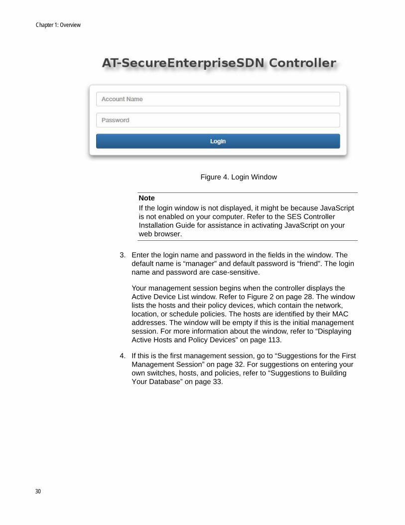
The SES controller’s login window is shown in Figure 4 on page 30.
29
Chapter 1: Overview
Figure 4. Login Window
NoteIf the login window is not displayed, it might be because JavaScript is not enabled on your computer. Refer to the SES Controller Installation Guide for assistance in activating JavaScript on your web browser.
3. Enter the login name and password in the fields in the window. The default name is “manager” and default password is “friend”. The login name and password are case-sensitive.
Your management session begins when the controller displays the Active Device List window. Refer to Figure 2 on page 28. The window lists the hosts and their policy devices, which contain the network, location, or schedule policies. The hosts are identified by their MAC addresses. The window will be empty if this is the initial management session. For more information about the window, refer to “Displaying Active Hosts and Policy Devices” on page 113.
4. If this is the first management session, go to “Suggestions for the First Management Session” on page 32. For suggestions on entering your own switches, hosts, and policies, refer to “Suggestions to Building Your Database” on page 33.
30
SES Controller User Guide
Ending a Management Session
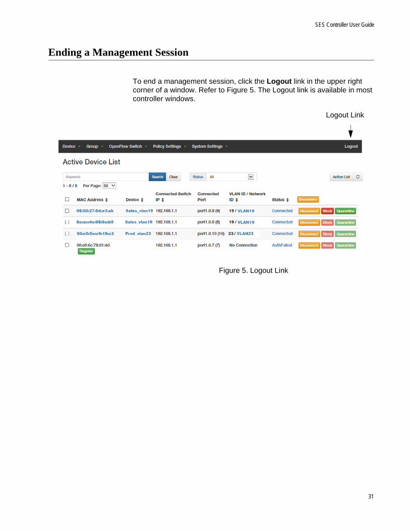
To end a management session, click the Logout link in the upper right corner of a window. Refer to Figure 5. The Logout link is available in most controller windows.
Figure 5. Logout Link
Logout Link
31

Chapter 1: Overview
Suggestions for the First Management Session
Here are suggestions on what to perform during your first management session of the SES controller:
1. Change the login password. Refer to “Changing the Password” on page 142. (You cannot change the login username.)
2. Install the AT-FL-SESC-Base-5YR base license. It provides support for up to of ten switches for five years. The SES controller must have the base license. For instructions, refer to “Managing the SES Controller Licenses and Software” on page 167.
3. If you purchased AT-FL-SESC-ADD50-5YR licenses, which add support for up to 50 switches for five years, install them with the instructions in“Managing the SES Controller Licenses and Software” on page 167. You can install any number of this license on the SES controller.
4. The SES controller’s installation program lets you configure only one network interface on the server. If the server has multiple network interfaces, perform the procedure in “Changing the IPv4 Address of the SES Controller” on page 143 to configure the other interfaces.
5. To manually set the date and time, refer to “Manually Setting the Date and Time” on page 154.
6. To set the date and time from an NTP server, refer to “Setting the Date and Time from an NTP Server” on page 155.
7. To set the VID of the quarantine VLAN for hosts that violate location or schedule policies, refer to “Configuring the OpenFlow SES Controller Settings” on page 170.
8. To install your own SSL security certificate for the HTTPS web server on the SES controller, refer to “Adding an SSL Certificate” on page 151.
9. After performing the above steps, go to “Suggestions to Building Your Database” on page 33.
NoteYou cannot use the SES controller to install OpenFlow subscription licenses on Allied Telesis switches. For that, use the AlliedWare Plus operating system, as explained in the SES Controller Installation Guide.
32

SES Controller User Guide
Suggestions to Building Your Database
Here are suggestions on how to start building your database of switches, hosts, and policies:
1. Verify that the SES controller and switches are communicating with each other over the control plane. To confirm this, perform “Displaying Active Switches” on page 42.
2. Switches learned automatically by the SES controller are initially entered as unregistered. They do not forward traffic from hosts on ports under OpenFlow control until you register them. This involves giving them descriptive names to make them easier to identify and designating the upstream ports, which connect the switches to higher network levels. For instructions, refer to “Registering Switches” on page 46.
3. Are there switches that are not yet connected to the control plane, but you want to enter manually into the SES controller? If so, perform the instructions in “Manually Adding Switches” on page 49 to add the switch to the controller.
4. For hosts requiring network, location, or schedule policies, plan the policies. Here are factors to consider:
What VLANs does your network require and what are to be the VIDs? You will need to add one network policy for each VLAN. For more information, refer to “Introduction to Network Policies” on page 77
Are there hosts you want to restrict to particular switches? If so, add location policies. For background information, refer to “Introduction to Location Policies” on page 84.
Are there hosts that should have access only during specified times or days? For them you can add schedule policies. Refer to “Introduction to Schedule Policies” on page 92.
5. Having decided on the details on step 5, add the necessary network, location, and schedule policies. For instructions, refer to Chapter 4, “Network, Location, and Schedule Policies” on page 75.
6. After adding the policies, add policy devices to assign hosts to their respective policies. For instructions, refer to Chapter 5, “Policy Devices” on page 99.
33

Chapter 1: Overview
NoteAdding a registered host to a policy device requires editing its properties, as explained in “Editing Hosts” on page 67. Use the Device ID field in the MAC Address Modify window to specify the host’s policy device.
7. Register the hosts, as explained in “Registering Hosts” on page 63.
At this point, the OpenFlow switches begin forwarding traffic from the hosts, in accordance with their network, location, or schedule policies.
34

SES Controller User Guide
Unsupported AlliedWare Plus Features
Allied Telesis does not support the following AlliedWare Plus features on switches managed with the SES controller:
VCStack
Rapid spanning tree protocol
IGMP Snooping TNC Query Solicitation on the OpenFlow native VLAN
Port mirroring on OpenFlow ports
Access control list (ACL) remark command on OpenFlow ports
The default setting for the features is enabled. They should be disabled during the installation process. For instructions, refer to the Secure Enterprise Software Defined Networking Controller Installation Guide.
35

Chapter 1: Overview
36
Chapter 2
OpenFlow Switches
This chapter includes the following sections:
“Introduction to OpenFlow Switches” on page 38
“Displaying Registered Switches” on page 39
“Displaying Active Switches” on page 42
“Registering Switches” on page 46
“Manually Adding Switches” on page 49
“Editing Switches” on page 52
“Deleting Flows from Switches” on page 53
“Deleting Switches from the SES Controller” on page 54
“Displaying Basic Information About Switches” on page 55
37

Chapter 2: OpenFlow Switches
Introduction to OpenFlow Switches
Switches have to have the OpenFlow protocol to be managed by the SES controller. They use it to forward host MAC addresses to the controller over the control plane and receive back network, location, and schedule policies, as well as other commands, to apply to their host ports.
How theController
Learns OpenFlowSwitches
The controller has two ways to learn about OpenFlow switches in the network. One way is automatically. When the OpenFlow protocol is active and configured, switches automatically establish communications with the controller over the control plane. If they are successful, the controller automatically registers their details.
You can also enter switches manually into the controller. You might do this to pre-configure them in the controller before connecting them to your network and activating the OpenFlow protocol. That way, the switches immediately begin to operate with their pre-defined configurations as soon as you connect them to your network.
Registered andUnregistered
Switches
Switches the controller learns automatically are initially entered as unregistered. Unregistered switches do not forward network traffic from hosts connected to ports under OpenFlow control. This is a security feature to prevent someone from adding an unauthorized OpenFlow switch to a network. Unregistered switches have to be registered before they can forward traffic. This is accomplished in the Active Device List window, as explained in “Registering Switches” on page 46.
Registering switches is not required for switches you enter manually into the SES controller. They can forward traffic as soon as you activate the OpenFlow protocol and connect them to the network.
Active andInactive Switches
OpenFlow switches, whether registered or not, can be either active or inactive. Active switches are actively communicating with the controller over the control plane and are forwarding traffic from hosts. Inactive switches are not communicating with the controller, possibly because they are powered off.
38
SES Controller User’s Guide
Displaying Registered Switches
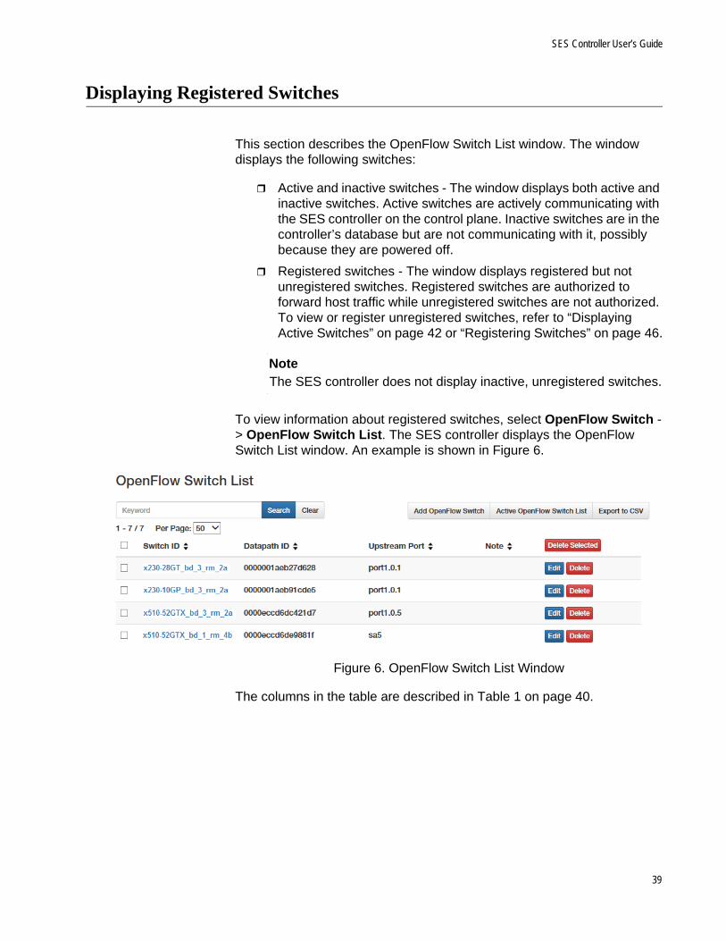
This section describes the OpenFlow Switch List window. The window displays the following switches:
Active and inactive switches - The window displays both active and inactive switches. Active switches are actively communicating with the SES controller on the control plane. Inactive switches are in the controller’s database but are not communicating with it, possibly because they are powered off.
Registered switches - The window displays registered but not unregistered switches. Registered switches are authorized to forward host traffic while unregistered switches are not authorized. To view or register unregistered switches, refer to “Displaying Active Switches” on page 42 or “Registering Switches” on page 46.
NoteThe SES controller does not display inactive, unregistered switches.
To view information about registered switches, select OpenFlow Switch -> OpenFlow Switch List. The SES controller displays the OpenFlow Switch List window. An example is shown in Figure 6.
Figure 6. OpenFlow Switch List Window
The columns in the table are described in Table 1 on page 40.
39
Chapter 2: OpenFlow Switches
The window options are described in Table 2.
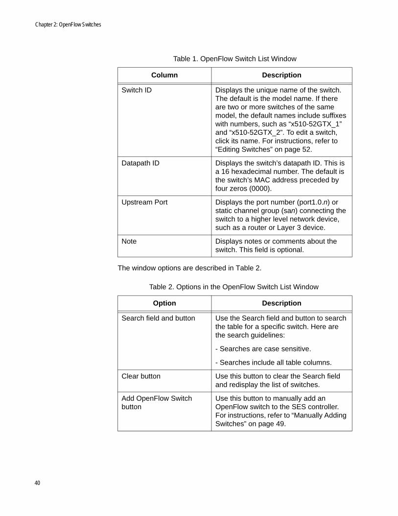
Table 1. OpenFlow Switch List Window
Column Description
Switch ID Displays the unique name of the switch. The default is the model name. If there are two or more switches of the same model, the default names include suffixes with numbers, such as “x510-52GTX_1” and “x510-52GTX_2”. To edit a switch, click its name. For instructions, refer to “Editing Switches” on page 52.
Datapath ID Displays the switch’s datapath ID. This is a 16 hexadecimal number. The default is the switch’s MAC address preceded by four zeros (0000).
Upstream Port Displays the port number (port1.0.n) or static channel group (san) connecting the switch to a higher level network device, such as a router or Layer 3 device.
Note Displays notes or comments about the switch. This field is optional.
Table 2. Options in the OpenFlow Switch List Window
Option Description
Search field and button Use the Search field and button to search the table for a specific switch. Here are the search guidelines:
- Searches are case sensitive.
- Searches include all table columns.
Clear button Use this button to clear the Search field and redisplay the list of switches.
Add OpenFlow Switch button
Use this button to manually add an OpenFlow switch to the SES controller. For instructions, refer to “Manually Adding Switches” on page 49.
40

SES Controller User’s Guide
Export to CVS button Use this button to export the table in the window as a CVS file to your computer. After clicking the button, follow the prompts.
Delete Selected button Use this button to delete multiple switches from the SES controller simultaneously. For instructions, refer to “Deleting Switches from the SES Controller” on page 54.
Edit button Use this button to edit switches. For instructions, refer to “Editing Switches” on page 52.
Delete button Use this button to delete switches from the SES controller, one at a time. For instructions, refer to “Deleting Switches from the SES Controller” on page 54.
Table 2. Options in the OpenFlow Switch List Window (Continued)
Option Description
41
Chapter 2: OpenFlow Switches
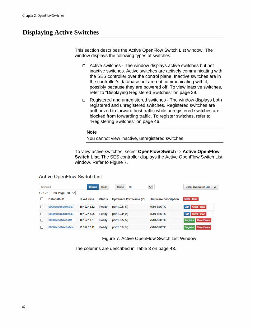
Displaying Active Switches
This section describes the Active OpenFlow Switch List window. The window displays the following types of switches:
Active switches - The window displays active switches but not inactive switches. Active switches are actively communicating with the SES controller over the control plane. Inactive switches are in the controller’s database but are not communicating with it, possibly because they are powered off. To view inactive switches, refer to “Displaying Registered Switches” on page 39.
Registered and unregistered switches - The window displays both registered and unregistered switches. Registered switches are authorized to forward host traffic while unregistered switches are blocked from forwarding traffic. To register switches, refer to “Registering Switches” on page 46.
NoteYou cannot view inactive, unregistered switches.
To view active switches, select OpenFlow Switch -> Active OpenFlow Switch List. The SES controller displays the Active OpenFlow Switch List window. Refer to Figure 7.
Figure 7. Active OpenFlow Switch List Window
The columns are described in Table 3 on page 43.
42
SES Controller User’s Guide
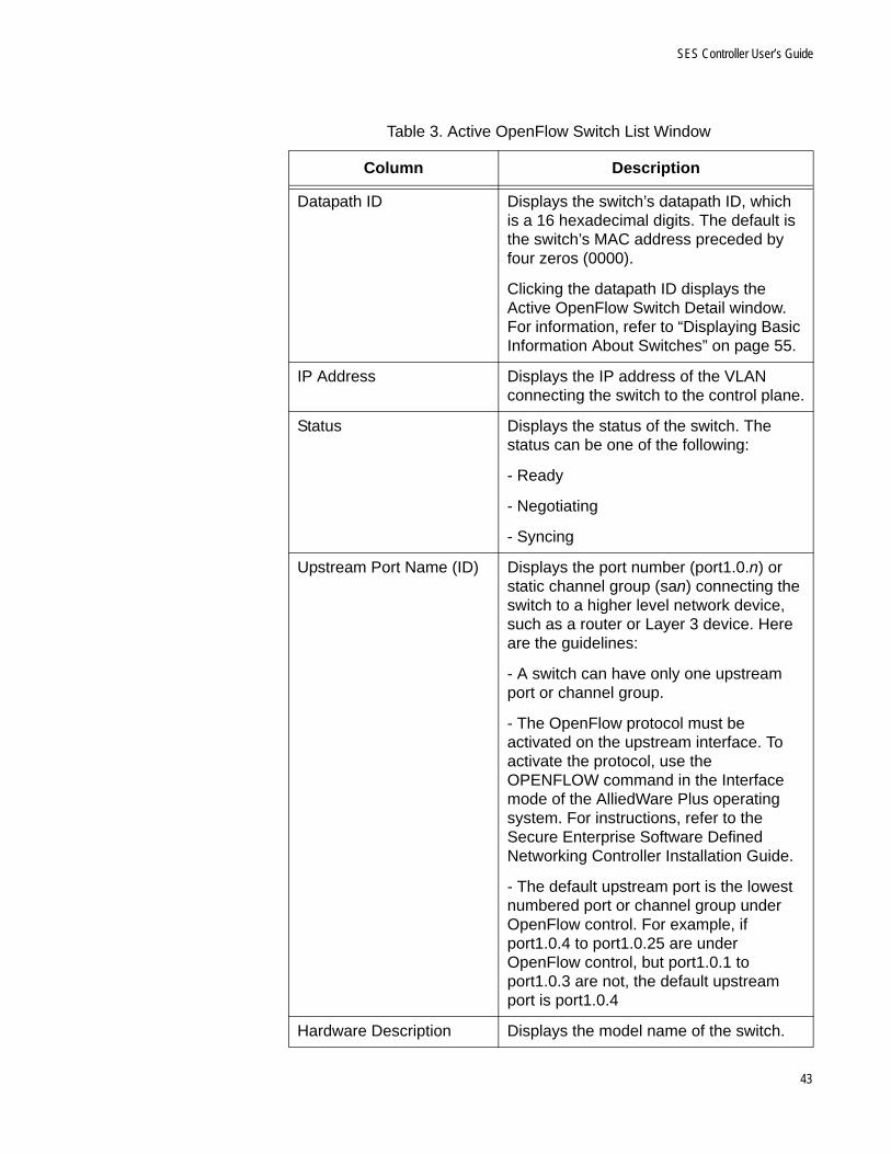
Table 3. Active OpenFlow Switch List Window
Column Description
Datapath ID Displays the switch’s datapath ID, which is a 16 hexadecimal digits. The default is the switch’s MAC address preceded by four zeros (0000).
Clicking the datapath ID displays the Active OpenFlow Switch Detail window. For information, refer to “Displaying Basic Information About Switches” on page 55.
IP Address Displays the IP address of the VLAN connecting the switch to the control plane.
Status Displays the status of the switch. The status can be one of the following:
- Ready
- Negotiating
- Syncing
Upstream Port Name (ID) Displays the port number (port1.0.n) or static channel group (san) connecting the switch to a higher level network device, such as a router or Layer 3 device. Here are the guidelines:
- A switch can have only one upstream port or channel group.
- The OpenFlow protocol must be activated on the upstream interface. To activate the protocol, use the OPENFLOW command in the Interface mode of the AlliedWare Plus operating system. For instructions, refer to the Secure Enterprise Software Defined Networking Controller Installation Guide.
- The default upstream port is the lowest numbered port or channel group under OpenFlow control. For example, if port1.0.4 to port1.0.25 are under OpenFlow control, but port1.0.1 to port1.0.3 are not, the default upstream port is port1.0.4
Hardware Description Displays the model name of the switch.
43
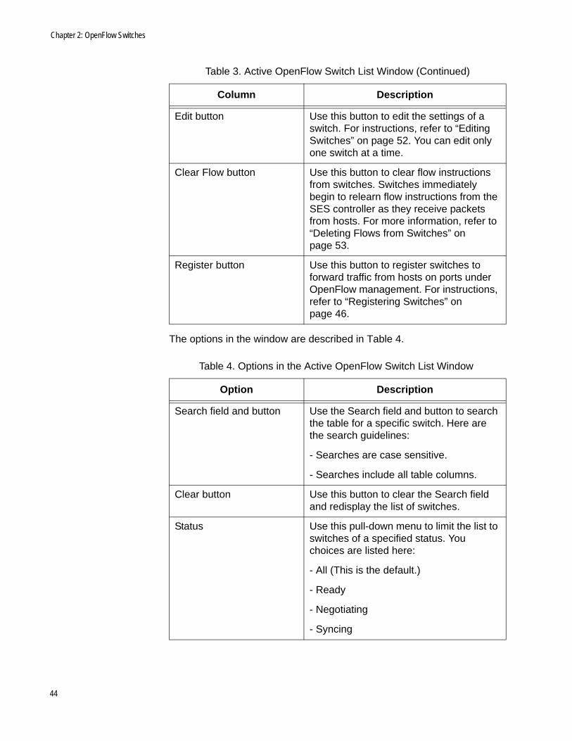
Chapter 2: OpenFlow Switches
The options in the window are described in Table 4.
Edit button Use this button to edit the settings of a switch. For instructions, refer to “Editing Switches” on page 52. You can edit only one switch at a time.
Clear Flow button Use this button to clear flow instructions from switches. Switches immediately begin to relearn flow instructions from the SES controller as they receive packets from hosts. For more information, refer to “Deleting Flows from Switches” on page 53.
Register button Use this button to register switches to forward traffic from hosts on ports under OpenFlow management. For instructions, refer to “Registering Switches” on page 46.
Table 4. Options in the Active OpenFlow Switch List Window
Option Description
Search field and button Use the Search field and button to search the table for a specific switch. Here are the search guidelines:
- Searches are case sensitive.
- Searches include all table columns.
Clear button Use this button to clear the Search field and redisplay the list of switches.
Status Use this pull-down menu to limit the list to switches of a specified status. You choices are listed here:
- All (This is the default.)
- Ready
- Negotiating
- Syncing
Table 3. Active OpenFlow Switch List Window (Continued)
Column Description
44
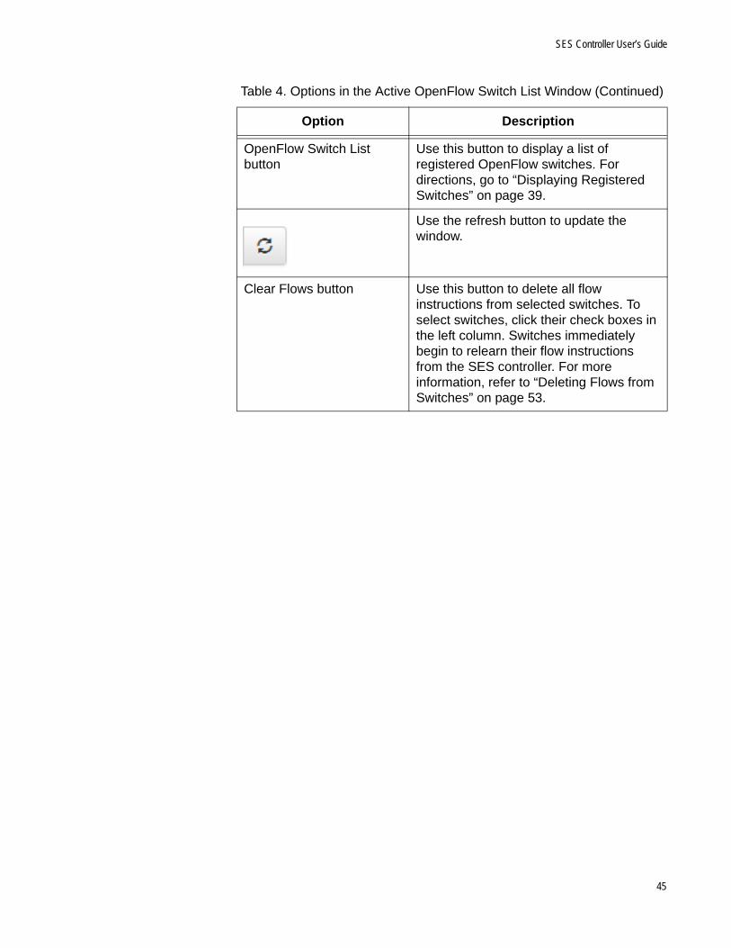
SES Controller User’s Guide
OpenFlow Switch List button
Use this button to display a list of registered OpenFlow switches. For directions, go to “Displaying Registered Switches” on page 39.
Use the refresh button to update the window.
Clear Flows button Use this button to delete all flow instructions from selected switches. To select switches, click their check boxes in the left column. Switches immediately begin to relearn their flow instructions from the SES controller. For more information, refer to “Deleting Flows from Switches” on page 53.
Table 4. Options in the Active OpenFlow Switch List Window (Continued)
Option Description
45
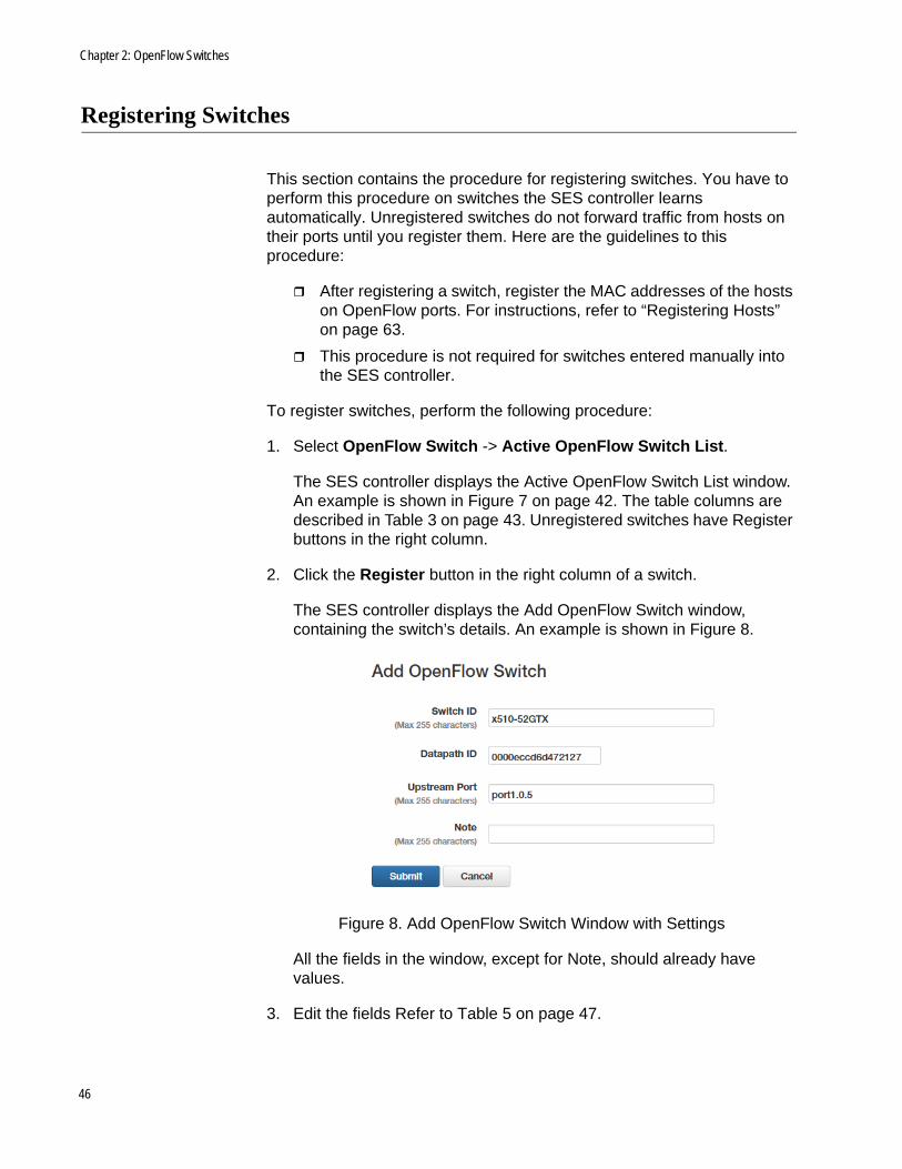
Chapter 2: OpenFlow Switches
Registering Switches
This section contains the procedure for registering switches. You have to perform this procedure on switches the SES controller learns automatically. Unregistered switches do not forward traffic from hosts on their ports until you register them. Here are the guidelines to this procedure:
After registering a switch, register the MAC addresses of the hosts on OpenFlow ports. For instructions, refer to “Registering Hosts” on page 63.
This procedure is not required for switches entered manually into the SES controller.
To register switches, perform the following procedure:
1. Select OpenFlow Switch -> Active OpenFlow Switch List.
The SES controller displays the Active OpenFlow Switch List window. An example is shown in Figure 7 on page 42. The table columns are described in Table 3 on page 43. Unregistered switches have Register buttons in the right column.
2. Click the Register button in the right column of a switch.
The SES controller displays the Add OpenFlow Switch window, containing the switch’s details. An example is shown in Figure 8.
Figure 8. Add OpenFlow Switch Window with Settings
All the fields in the window, except for Note, should already have values.
3. Edit the fields Refer to Table 5 on page 47.
46
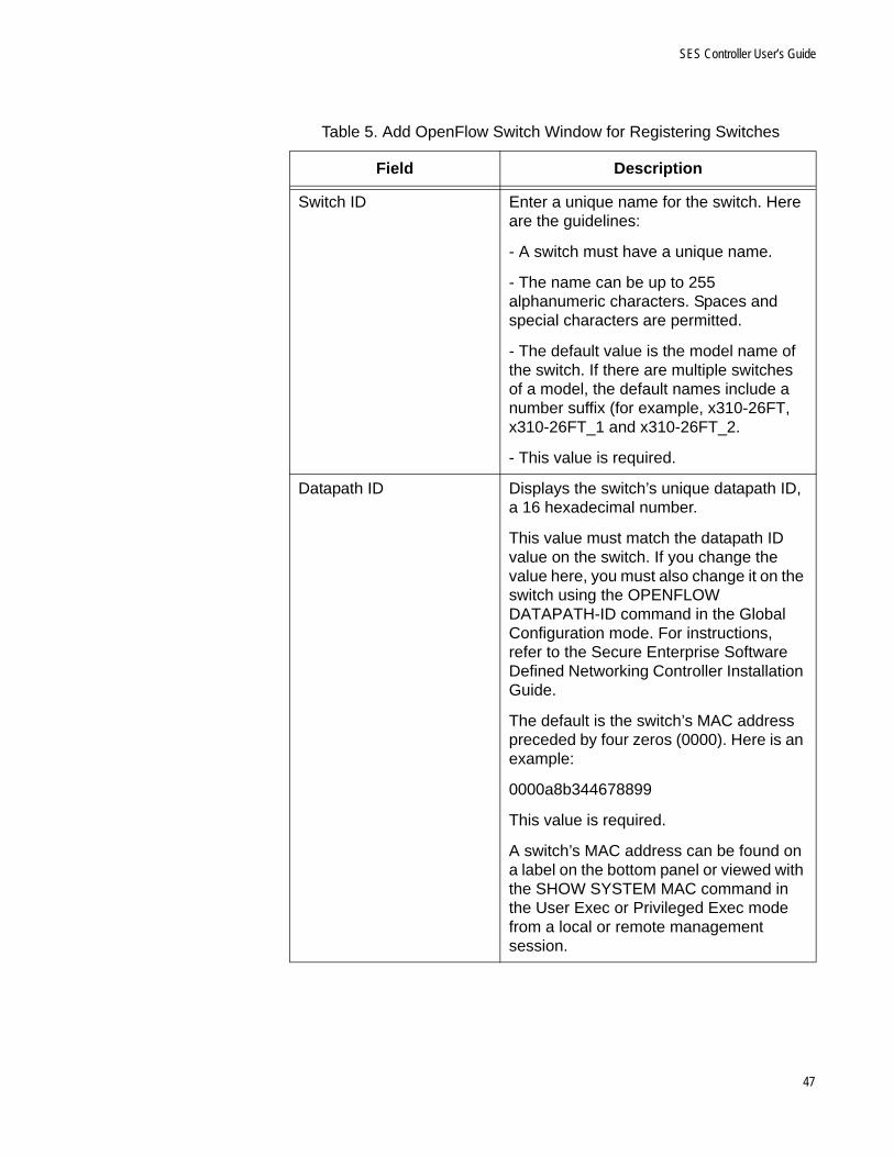
SES Controller User’s Guide
Table 5. Add OpenFlow Switch Window for Registering Switches
Field Description
Switch ID Enter a unique name for the switch. Here are the guidelines:
- A switch must have a unique name.
- The name can be up to 255 alphanumeric characters. Spaces and special characters are permitted.
- The default value is the model name of the switch. If there are multiple switches of a model, the default names include a number suffix (for example, x310-26FT, x310-26FT_1 and x310-26FT_2.
- This value is required.
Datapath ID Displays the switch’s unique datapath ID, a 16 hexadecimal number.
This value must match the datapath ID value on the switch. If you change the value here, you must also change it on the switch using the OPENFLOW DATAPATH-ID command in the Global Configuration mode. For instructions, refer to the Secure Enterprise Software Defined Networking Controller Installation Guide.
The default is the switch’s MAC address preceded by four zeros (0000). Here is an example:
0000a8b344678899
This value is required.
A switch’s MAC address can be found on a label on the bottom panel or viewed with the SHOW SYSTEM MAC command in the User Exec or Privileged Exec mode from a local or remote management session.
47

Chapter 2: OpenFlow Switches
4. Click the Submit button to register the switch or the Cancel button to cancel the procedure.
The switch is now authorized to forward traffic from hosts on its OpenFlow ports.
5. To register the MAC addresses of the hosts on its ports, refer to “Registering Hosts” on page 63.
Upstream Port Enter the port number (port1.0.n) or static channel group (san) of the upstream port on the switch. The upstream port connects the switch to a higher level network device, such as a router or other Layer 3 device. Here are the guidelines:
- You can enter only one port or channel group.
- The OpenFlow protocol must be activated on the port or channel group. To activate the protocol, use the OPENFLOW command in the Interface mode of the AlliedWare Plus operating system. For instructions, refer to the Secure Enterprise Software Defined Networking Controller Installation Guide.
- The default value is the lowest numbered OpenFlow port or channel group on the switch. For example, the default is port1.0.4 if the OpenFlow protocol is enabled on that port but not port1.0.1 to port1.0.3.
- This value is required.
Note Enter notes or comments about the switch. This field is optional.
Table 5. Add OpenFlow Switch Window for Registering Switches
Field Description
48

SES Controller User’s Guide
Manually Adding Switches
This section contains the procedure for manually adding OpenFlow switches to the SES controller. In most cases you will not need to perform the steps because the controller can learn OpenFlow switches automatically. The only situation when you might perform the procedure is to pre-configure switches in the controller before connecting them to your network.
NoteYou do not register switches that you manually add to the SES controller. The controller automatically registers them.
You have to provide the following information to manually add a switch to the SES controller:
Switch ID - Unique switch name.
Datapath ID - Unique 16 hexadecimal number.
Upstream port - Switch port that connects to a higher level device, such as a router or other Layer 3 device.
Note - Switch description. This value is optional.
To manually add an OpenFlow switch to the controller, perform the following procedure:
1. Select OpenFlow Switch -> Add OpenFlow Switch.
The Add OpenFlow Switch window is shown in Figure 9.
Figure 9. Add OpenFlow Switch Window
2. Fill in the fields in the window. Refer to Table 6 on page 50.
49

Chapter 2: OpenFlow Switches
Table 6. Add OpenFlow Switch Window for Manually Adding Switches
Field Description
Switch ID Enter a name for the switch. Here are the guidelines:
- The name must be unique from all other switch names.
- It can be up to 255 alphanumeric characters. Spaces and special characters are permitted.
- This value is required.
Datapath ID Enter a unique datapath ID for the switch A datapath ID is 16 hexadecimal digits. The default is the switch’s MAC address preceded by four zeros (0000). Here is an example:
0000a8b344678899
A switch’s MAC address can be found on a label on the bottom panel or viewed with the SHOW SYSTEM MAC command in the User Exec or Privileged Exec mode from a local or remote management session.You can enter only one datapath.
50
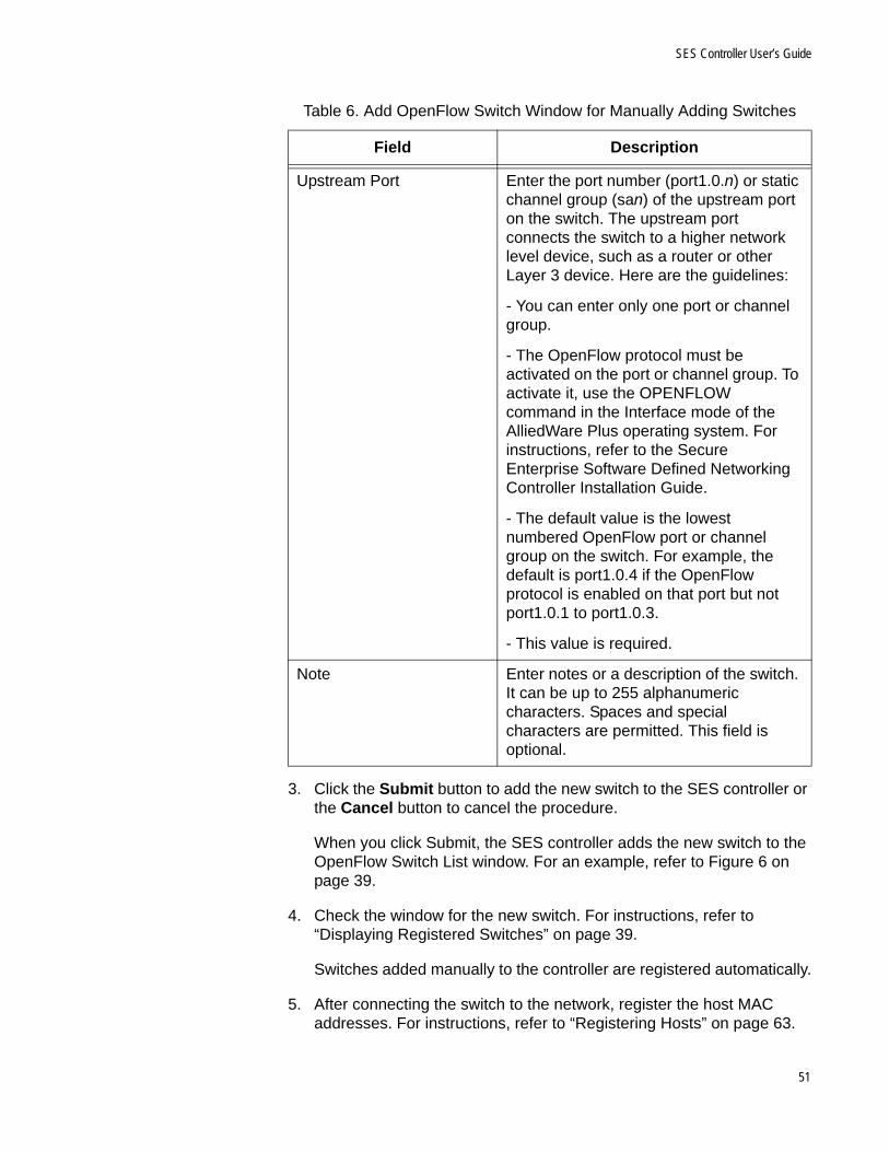
SES Controller User’s Guide
3. Click the Submit button to add the new switch to the SES controller or the Cancel button to cancel the procedure.
When you click Submit, the SES controller adds the new switch to the OpenFlow Switch List window. For an example, refer to Figure 6 on page 39.
4. Check the window for the new switch. For instructions, refer to “Displaying Registered Switches” on page 39.
Switches added manually to the controller are registered automatically.
5. After connecting the switch to the network, register the host MAC addresses. For instructions, refer to “Registering Hosts” on page 63.
Upstream Port Enter the port number (port1.0.n) or static channel group (san) of the upstream port on the switch. The upstream port connects the switch to a higher network level device, such as a router or other Layer 3 device. Here are the guidelines:
- You can enter only one port or channel group.
- The OpenFlow protocol must be activated on the port or channel group. To activate it, use the OPENFLOW command in the Interface mode of the AlliedWare Plus operating system. For instructions, refer to the Secure Enterprise Software Defined Networking Controller Installation Guide.
- The default value is the lowest numbered OpenFlow port or channel group on the switch. For example, the default is port1.0.4 if the OpenFlow protocol is enabled on that port but not port1.0.1 to port1.0.3.
- This value is required.
Note Enter notes or a description of the switch. It can be up to 255 alphanumeric characters. Spaces and special characters are permitted. This field is optional.
Table 6. Add OpenFlow Switch Window for Manually Adding Switches
Field Description
51

Chapter 2: OpenFlow Switches
Editing Switches
This section contains the procedure for editing registered OpenFlow switches. To edit the settings of unregistered switches, you first have to register them. For instructions, refer to “Registering Switches” on page 46.
To edit a registered switch, perform the following procedure:
1. Select OpenFlow Switch -> OpenFlow Switch List.
The SES controller displays the OpenFlow Switch List window. Refer to Figure 6 on page 39
2. Click the Edit button of a switch to edit. You can edit only one switch at a time.
The SES controller displays the Modify OpenFlow Switch window with the parameter settings of the switch. Refer to Figure 10.
Figure 10. Modify OpenFlow Switch Window
3. Edit the fields in the window. Refer to Table 6 on page 50.
4. After editing the fields, click the Submit button to add your changes or the Cancel button to cancel the procedure.
The SES controller displays the OpenFlow Switch List window again.
5. Repeat this procedure starting with step 2 to edit other registered switches.
52
SES Controller User’s Guide
Deleting Flows from Switches
This section contains the procedure for deleting flows from switches. Flows are instructions from the SES controller to the switches on how to forward host traffic. Deleting flows forces switches to relearn them from the controller. You might perform the procedure if you believe a switch is not correctly forwarding network traffic because its flow instructions are incorrect.
Caution
Deleting flow instructions might temporary reduce network performance while a switch relearns them from the SES controller.
To delete flows from a switch, perform the following procedure:
1. Select OpenFlow Switch -> Active OpenFlow Switch List.
The SES controller displays the Active OpenFlow Switch List window. Refer to Figure 7 on page 42.
2. Do one of the following:
To delete the flows from a single switch, click its Clear Flows button in the right column.
To delete flows from multiple switches, click their check boxes in the left column and then click the Clear Flows button above the right column.
The SES controller displays a confirmation prompt.
3. Click OK to delete the flows from the switches or Cancel to cancel the procedure.
If you click OK, a switch deletes all its flows and immediately begins to relearn them from the SES controller as it receives host packets on its ports.
53

Chapter 2: OpenFlow Switches
Deleting Switches from the SES Controller
This section contains the procedure for deleting switches from the SES controller. You might perform the procedure for the following reasons:
You have removed switches from the network.
You want to unregister active switches to stop them from forwarding host traffic.
Caution
Exercise caution when deleting switches from the controller. Hosts that are actively using deleted switches to access a network will lose network connectivity.
To delete switches from the SES controller, perform the following procedure:
1. Select OpenFlow Switch -> OpenFlow Switch List.
The SES controller displays the OpenFlow Switch List window. Refer to Figure 6 on page 39
2. Do one of the following:
To delete a single switch, click its Delete button in the right column of the table.
To delete multiple switches, click their check boxes in the left column and then click the Delete Selected button above the right column.
The SES controller displays a confirmation prompt.
3. Click the OK button to delete the switch or the Cancel button to cancel the procedure.
If deleted switches are active, the SES controller automatically relearns them as unregistered to prevent them from forwarding traffic until you register them again. For instructions, refer to “Registering Switches” on page 46.
54

SES Controller User’s Guide
Displaying Basic Information About Switches
To view basic information about active switches, perform the following procedure:
1. Select OpenFlow Switch -> Active OpenFlow Switch List. The SES controller displays the Active OpenFlow Switch List window. Refer to Figure 7 on page 42.
2. Click the Datapath ID of a switch to view its basic information.
The SES controller displays the Active OpenFlow Switch Detail window. An example is shown in Figure 11.
Figure 11. Active OpenFlow Switch Detail Window
The columns are described in Table 7 on page 56.
55
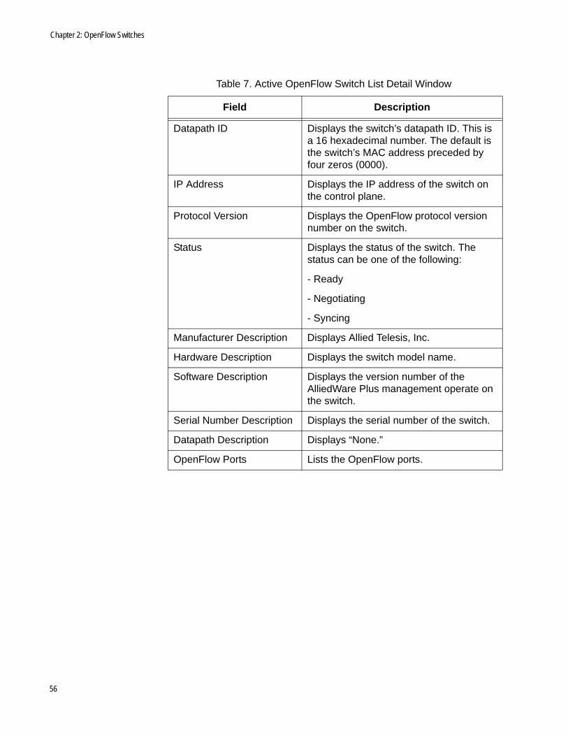
Chapter 2: OpenFlow Switches
Table 7. Active OpenFlow Switch List Detail Window
Field Description
Datapath ID Displays the switch’s datapath ID. This is a 16 hexadecimal number. The default is the switch’s MAC address preceded by four zeros (0000).
IP Address Displays the IP address of the switch on the control plane.
Protocol Version Displays the OpenFlow protocol version number on the switch.
Status Displays the status of the switch. The status can be one of the following:
- Ready
- Negotiating
- Syncing
Manufacturer Description Displays Allied Telesis, Inc.
Hardware Description Displays the switch model name.
Software Description Displays the version number of the AlliedWare Plus management operate on the switch.
Serial Number Description Displays the serial number of the switch.
Datapath Description Displays “None.”
OpenFlow Ports Lists the OpenFlow ports.
56

Chapter 3
Hosts
This chapter includes the following sections:
“Introduction to Hosts” on page 58
“Displaying Registered Hosts” on page 60
“Registering Hosts” on page 63
“Manually Adding Hosts” on page 66
“Editing Hosts” on page 67
“Isolating Hosts” on page 68
“Viewing or Restoring Isolated Hosts” on page 70
“Specifying the Quarantine VLAN ID” on page 72
“Deleting Hosts from the SES Controller” on page 73
57
Chapter 3: Hosts
Introduction to Hosts
Hosts are edge devices, such as laptop computers or smart phones. The SES controller identifies hosts by their unique MAC addresses. It stores their addresses in its database and transmits the appropriate policies to the switches to configure the ports as hosts begin forwarding traffic through the switches.
How the SESController
Learns Hosts
The SES controller has two ways to learn host MAC addresses:
Automatically - When OpenFlow switches receive network packets from hosts with unknown MAC address, they forward the packets to the SES controller over the control plane. The controller checks the packets’ source MAC addresses against its list of addresses in its database and automatically adds those not already learned.
Host MAC addresses learned in this manner are initially entered as unregistered in the database, meaning that although the SES controller has learned the addresses, the switches continue blocking the host traffic. It is not until you manually register the hosts that switches begin forwarding their traffic. Additionally, hosts learned automatically initially have no network policies. If you register them without assigning them network policies, OpenFlow switches forward their packets as untagged, making them members of the OpenFlow native VLAN. For instructions, refer to “Registering Hosts” on page 63.
Manually - You can also manually enter host MAC addresses and assign them network policies to pre-configure the SES controller, before connecting the hosts. Unlike hosts whose addresses are learned automatically, these are automatically registered. Switches begin forwarding their traffic as soon as the hosts are connected to the network.
Registered andUnregistered
Hosts
When the SES controller automatically learns new host MAC addresses from OpenFlow switches, it initially adds them as unregistered in its database. Hosts of unregistered MAC addresses cannot forward traffic through switches until you manually register their addresses. For instructions, refer to “Registering Hosts” on page 63.
Host MAC addresses you enter manually into the SES controller are automatically registered.
Active andInactive Hosts
Host MAC addresses can be active or inactive:
Active - Active hosts are connected to switches ports and powered on. They do not have to be transmitting packets to be in this state. Hosts with unregistered MAC addresses have to be active for you
58

SES Controller User Guide
to register their addresses or you can manually enter them into the SES controller.
Inactive - Inactive hosts are hosts the SES controller has learned, either automatically or manually, but are currently not detected by the switches, either because they are not connected to any switches or are powered off.
59

Chapter 3: Hosts
Displaying Registered Hosts
This section describes the MAC Address List window. Details about the window are given here:
The window displays registered but not unregistered hosts. Registered hosts are approved to forward traffic through OpenFlow switches. Unregistered hosts have not been approved to forward traffic. For more information, refer to “Registered and Unregistered Hosts” on page 58. To view unregistered hosts, refer to “Registering Hosts” on page 63.
The window displays both active and inactive host MAC addresses. The latter are hosts the SES controller has learned but are not detected, possibly because they are powered off. For more information, refer to “Active and Inactive Hosts” on page 58.
It includes a column, titled Device ID, that lists the names of the policy devices that are assigned to the hosts. Policy devices contain the network, location, and schedule policies for hosts. For information, refer to Chapter 4, “Network, Location, and Schedule Policies” on page 75.
To view active and inactive registered hosts, select Device -> MAC Address List. An example of the MAC Address List window is shown in Figure 12.
Figure 12. MAC Address List Window
The window columns are described in Table 8 on page 61.
60

SES Controller User Guide
The options in the window are described in Table 9.
Table 8. MAC Address List Window
Column Description
MAC Address Displays the MAC address of a registered host. Clicking the address displays the MAC Address Modify window, for editing the MAC address entry. For information, refer to “Editing Hosts” on page 67.
Name Displays the host’s name or other information. This field is optional.
Device ID Displays the name of the policy device containing the host’s network, location, and schedule policies. A host can have only one policy device. This field is empty if a host is not assigned a policy device. To edit a policy device, click its name. For information, refer to “Editing Policy Devices” on page 124.
Note Displays notes or comments about the host. This field is optional.
Table 9. Options in the MAC Address List Window
Column Description
Search field and button Use the Search field and button to search the table for a specific host. Here are the search guidelines:
- The search is case sensitive.
- Searches include all table columns.
Add MAC Address button Use this button to manually add host MAC addresses to the SES controller. For instructions, refer to “Manually Adding Hosts” on page 66.
Active Device List button Use this button to display the Active Device List window, listing the active hosts and their policy devices. For information, refer to “Displaying Active Hosts and Policy Devices” on page 113.
61

Chapter 3: Hosts
Export to CVS button Use this button to export the table in the window as a CVS file to your computer. After clicking the button, follow the prompts to save the table.
Delete Selected Use this button to delete multiple MAC addresses from the SES controller. For instructions, refer to “Deleting Hosts from the SES Controller” on page 73.
Edit Button Use this button to edit MAC addresses. For instructions, refer to “Editing Hosts” on page 67.
Delete Button Use this button to delete MAC addresses from the SES controller, one at a time. For instructions, refer to “Deleting Hosts from the SES Controller” on page 73.
Table 9. Options in the MAC Address List Window (Continued)
Column Description
62

SES Controller User Guide
Registering Hosts
The MAC addresses of hosts that the SES controller learns automatically from the OpenFlow switches are initially designated as unregistered. Switches do not forward traffic from unregistered hosts until you register their addresses. This security feature prevents new hosts from gaining network access without your authorization. For more information, refer to “Registered and Unregistered Hosts” on page 58.
Registering hosts requires the following information:
MAC address - The SES controller learns the address automatically.
Name - The host name. This field is optional.
Policy device - The network, location, and schedule policies for the host. If you do not specify a network policy, the host’s packets are forwarded as untagged packets in the OpenFlow native VLAN. Hosts without location or schedule policies can access networks from any switch at any time. For further information, refer to Chapter 4, “Network, Location, and Schedule Policies” on page 75 and Chapter 5, “Policy Devices” on page 99.
Note - Host description. This field is optional.
To register hosts so that switches forward their traffic, perform the following procedure:
1. Select Device -> Active Device List.
The SES controller displays the Active Device List window. Refer to Figure 13. Unregistered hosts have a Register button beneath their MAC addresses in the first column.
Figure 13. Active Device List Window
63
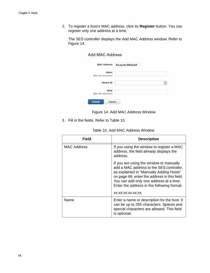
Chapter 3: Hosts
2. To register a host’s MAC address, click its Register button. You can register only one address at a time.
The SES controller displays the Add MAC Address window. Refer to Figure 14.
Figure 14. Add MAC Address Window
3. Fill in the fields. Refer to Table 10.
Table 10. Add MAC Address Window
Field Description
MAC Address If you using the window to register a MAC address, the field already displays the address.
If you are using the window to manually add a MAC address to the SES controller, as explained in “Manually Adding Hosts” on page 66, enter the address in this field. You can add only one address at a time. Enter the address in the following format:
xx:xx:xx:xx:xx:xx
Name Enter a name or description for the host. It can be up to 255 characters. Spaces and special characters are allowed. This field is optional.
64

SES Controller User Guide
4. Click the Submit button to register the address in the SES controller or the Cancel button to cancel the procedure.
When you click the Submit button the SES controller adds the registered address to the MAC Address List window. Refer to Figure 12 on page 60. The host is now authorized to forward traffic through its switch, in accordance with the instructions in its policy device.
Device ID From the pull-down menu select the policy device for the host. The device defines its the network, location, and schedule policies. Here are the guidelines:
- A host can have only one policy device.
- You can leave the field empty if you do not want to assign a policy device to a host or have not added the policy device yet to the SES controller. A host without a policy device becomes a member of the OpenFlow native VLAN on its switch.
For more information, refer to Chapter 5, “Policy Devices” on page 99.
Note Enter a description for the host of up to 255 characters. Spaces and special characters are allowed. This field is optional.
Table 10. Add MAC Address Window (Continued)
Field Description
65

Chapter 3: Hosts
Manually Adding Hosts
This section contains the procedure for manually adding hosts to the SES controller. This involves specifying the MAC addresses of the hosts, adding names and descriptions to make them easier to identify, and, most importantly, designating their policy devices, containing their network, location, and schedule policies.
This procedure will probably not be necessary because the SES controller can automatically learn the MAC addresses of hosts from the OpenFlow switches. You might perform this procedure to pre-configure the SES controller for hosts before connecting them to the switches.
NoteHost MAC addresses you enter manually are automatically registered by the SES controller.
Adding a host requires the following information:
Host’s MAC address
Name - The host name. This field is optional.
Policy device - The network, location, and schedule policies for the host. If you do not specify a network policy, the host’s packets are forwarded as untagged packets in the OpenFlow native VLAN. Hosts without location or schedule policies can access networks from any switch at any time. For further information, refer to Chapter 4, “Network, Location, and Schedule Policies” on page 75.
Note - Comment or description of the host. This field is optional.
To manually add a host to the SES controller, perform this procedure:
1. Select Device -> Add MAC Address.
The SES controller displays the Add MAC Address window, shown in Figure 14 on page 64.
2. Fill in the fields. Refer to Table 10 on page 64.
3. Click the Submit button to add the host’s MAC address to the SES controller or the Cancel button to cancel the procedure.
When you click the Submit button, the SES controller adds the MAC address as registered. The corresponding host can forward traffic through its OpenFlow switch after you connect it to the network.
4. To verify the addition of the host’s MAC address, perform “Displaying Registered Hosts” on page 60.
66

SES Controller User Guide
Editing Hosts
You can edit these host settings:
MAC address
Host’s name. This is optional.
Policy device. This is optional.
Host description. This is optional.
To edit the settings of a host’s MAC address, perform the following procedure:
1. Select Device -> MAC Address List.
The SES controller displays the MAC Address List window, which lists the MAC addresses of registered hosts. An example of the window is shown in Figure 12 on page 60. (To edit unregistered hosts, you have to register them. For instructions, refer to “Registering Hosts” on page 63.)
2. Click the Edit button in the right column of the host MAC address you want to edit. You can edit only one address at a time.
The SES controller displays the Modify MAC Address window, containing the parameter settings of the selected MAC address. An example is shown in Figure 15.
Figure 15. MAC Address Modify Window
3. Edit the parameter settings. Refer Table 10 on page 64.
4. After editing the fields, click the Submit button to add your changes or the Cancel button to cancel the procedure.
67
Chapter 3: Hosts
Isolating Hosts
You can use the SES controller to manually isolate hosts from your network. You might perform this procedure to block unauthorized hosts or hosts who might represent a danger to the network. The controller supports the following types of isolation:
Disconnect - Disables the link between the OpenFlow switch and host by shutting down the host’s port on the switch. The link remains disabled even if you disconnect the network cable or connect a different host to it. If the port has Power over Ethernet (PoE), power is not interrupted.
Block - Stops the switch from forwarding a host’s traffic, but the port remains up. Traffic remains blocked even if you disconnect the network cable or connect a different host to it.
Quarantine - A host is assigned a VID to an isolated VLAN. For directions on how to specify the quarantine VLAN ID, refer to “Specifying the Quarantine VLAN ID” on page 72.
For instructions on how to restore isolated hosts, refer to “Viewing or Restoring Isolated Hosts” on page 70.
To isolate a host, perform the following procedure:
1. Select Device -> Active Device List.
The SES controller displays the Active Device List window. Refer to Figure 43 on page 113.
2. Do one of the following:
To isolate a single host, click its Disconnect, Block, or Quarantine button in the right column. You can select only one action.
To disconnect multiple hosts, click the check boxes of the hosts in the left column and click the Disconnect button in the top right column.
The SES controller displays a confirmation prompt.
3. Click the OK button to isolate the host or the Cancel button to cancel the procedure.
4. To verify a host’s isolation status, examine the Status column. Its status should be Disconnected, Blocked, or Quarantined. The example in Figure 16 on page 69 shows a quarantined host.
68

SES Controller User Guide
Figure 16. Example Status of an Isolated Host
69
Chapter 3: Hosts
Viewing or Restoring Isolated Hosts
This section explains two ways to view or restore hosts who have been disconnected, blocked, or quarantined. One way is with the Active Device List window in the Device menu and the other is with the Action List window in the Policy Settings menu.
The action the SES controller performs in restoring a host depends on the type of isolation, as outlined here:
Restoring a disconnected host- The SES controller instructs the switch to activate the host’s port, allowing the host to forward traffic.
Restoring a blocked host - The controller instructs the switch to unblock the host’s traffic, allowing the host to forward traffic.
Restoring a quarantined host - The controller issues the host’s network policy to the switch, restoring the host to its original VLAN assignment.
To view or restore isolated hosts using the Active Device List window in the Device menu, perform the following procedure:
1. Select Device -> Active Device List.
The SES controller displays the Active Device List window. Hosts who are isolated have a status of Disconnect, Block, or Quarantine. They also have Recover buttons beneath the status. For an example, refer to Figure 16 on page 69.
2. Click the Recover button beneath the status of the host. You can recover only one host at a time.
The SES controller displays a confirmation prompt.
3. Click the OK button to restore the host or the Cancel button to cancel the procedure.
To restore isolated hosts using the Action List window in the Policy Settings window, perform the following procedure:
1. Select Policy Settings -> Action List.
The SES controller displays the isolated hosts in the Active Device List window. An example is shown in Figure 17 on page 71.
70
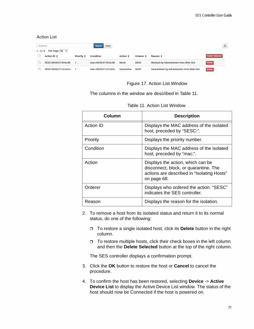
SES Controller User Guide
Figure 17. Action List Window
The columns in the window are described in Table 11.
2. To remove a host from its isolated status and return it to its normal status, do one of the following:
To restore a single isolated host, click its Delete button in the right column.
To restore multiple hosts, click their check boxes in the left column and then the Delete Selected button at the top of the right column.
The SES controller displays a confirmation prompt.
3. Click the OK button to restore the host or Cancel to cancel the procedure.
4. To confirm the host has been restored, selecting Device -> Active Device List to display the Active Device List window. The status of the host should now be Connected if the host is powered on.
Table 11. Action List Window
Column Description
Action ID Displays the MAC address of the isolated host, preceded by “SESC:”.
Priority Displays the priority number.
Condition Displays the MAC address of the isolated host, preceded by “mac:”.
Action Displays the action, which can be disconnect, block, or quarantine. The actions are described in “Isolating Hosts” on page 68.
Orderer Displays who ordered the action. “SESC” indicates the SES controller.
Reason Displays the reason for the isolation.
71

Chapter 3: Hosts
Specifying the Quarantine VLAN ID
You can isolate hosts by moving them to a separate VLAN. This is called quarantining hosts. Using this isolation method requires specifying the quarantine VID in the SES controller. You can specify only one quarantine VLAN.
NoteYou do not have to manually add the quarantine VLAN to OpenFlow switches. They automatically add the VLAN, if it does not already exist, when they move quarantined hosts to it.
To specify the VID for the quarantine VLAN, perform the following procedure:
1. Select System Settings - > OpenFlow Settings.
2. Select the Quarantine VLAN ID field and enter a new VID. The range is 0 to 4094.
Here are the guidelines to specifying the quarantine VID:
You can enter only one VID.
The default is 4089.
To use the OpenFlow native VLAN as the quarantine VLAN, enter 0 (zero), which is equivalent to not assigning a VID.
3. Click the Submit button to enter your change or the Cancel button to cancel the procedure.
72

SES Controller User Guide
Deleting Hosts from the SES Controller
This section contains the procedure for deleting host MAC addresses from the SES controller. You might perform this procedure to unregister addresses or delete obsolete addresses.
NoteDeleting MAC addresses of active hosts immediately blocks them from forwarding traffic through OpenFlow switches.
NoteThe SES controller immediately relearns addresses of active hosts. However, the addresses are learned as unregistered. The corresponding hosts cannot forward traffic through the switch until you register the addresses again. For instructions, refer to “Registering Hosts” on page 63.
To delete the MAC addresses of hosts from the SES controller, perform the following procedure:
1. Select Device -> MAC Address List.
The SES controller displays the MAC Address List window. Refer to Figure 12 on page 60
2. Do one of the following:
To delete one MAC address, click its Delete button in the right column.
To delete multiple MAC addresses, click their check boxes In the left column and then click the Delete Selected button in the upper right corner.
The SES controller displays a confirmation prompt.
3. Click the OK button to delete the selected addresses or the Cancel button to cancel the procedure.
The address of the host is deleted from the window. If the host is active, the SES controller relearns its address as unregistered. To view unregistered hosts, refer to “Registering Hosts” on page 63.
73

Chapter 3: Hosts
74

Chapter 4
Network, Location, and Schedule Policies
This chapter includes the following sections:
“Introduction to Network, Location, and Schedule Policies” on page 76
“Network Policies” on page 77
“Location Policies” on page 84
“Schedule Policies” on page 92
75

Chapter 4: Network, Location, and Schedule Policies
Introduction to Network, Location, and Schedule Policies
You use policies to manage hosts. There are three policy types. They are briefly described here:
Network policies; These policies define the VLAN memberships of hosts. Network policies identify VLANs by their VIDs.
Location policies: These policies specify the OpenFlow switches that hosts can use to access networks. Hosts with location policies can access networks only though switches defined in their policies. The switches are identified by their datapath IDs. Location policies can specify more than one switch.
Schedule policies: These policies specify the days and times hosts can access a network.
To assign policies to hosts, you add policy devices. These combine host’s MAC addresses with their appropriate policies. As an example, to assign a host to a VLAN with the VID 89, you add a network policy with the VID 89 and then add a policy device containing the host’s MAC address and network policy.
A host can have only one policy device, but a device can have more than one policy. For more information, refer to “Introduction to Policy Devices” on page 100.
76

SES Controller User Guide
Network Policies
The following ‘sections explain how to use network policies to assign hosts to VLANs. The sections are listed here:
“Introduction to Network Policies” next
“Displaying Network Policies” on page 78
“Adding Network Policies” on page 80
“Editing Network Policies” on page 82
“Deleting Network Policies” on page 83
Introduction toNetwork Policies
Network policies assign hosts to VLANs. VLANs are identified by VLAN IDs (VIDs). Here are the guidelines to network policies:
A network policy can have only one VID.
The VID range is 0 to 4094.
To assign a network policy to a host, you add a policy device. It specifies the host MAC address and appropriate network policy. For instructions, refer to Chapter 5, “Policy Devices” on page 99.
You do not have to manually add the VLANs defined in network policies to OpenFlow switches. Switches add them automatically after receiving network policies from the SES controller.
You can assign a network policy to more than one policy device.
You can assign more than one network policy to a policy device, but only the policy with the highest device priority (lowest number) is active.
Hosts without network policies or a policy with the VID 0 are assigned to the OpenFlow native VLAN. This is set with the OPENFLOW NATIVE VLAN command in the Global Configuration mode of the AlliedWare Plus operating software. For instructions, refer to the Secure Enterprise Software Defined Networking Controller Installation Guide.
Network packets from hosts with network policies are forwarded on the upstream interface as tagged packets, with the VIDs from the policies.
Network packets from hosts without network policies or with policies with the VID 0 are forwarded on the upstream interface as untagged packets.
Here is example of a network policy. This example assigns VID 112 to these three hosts:
42:33:66:c5:14:3e - J. Jones
77

Chapter 4: Network, Location, and Schedule Policies
8a:3a:9b:21:6a:43 - A. Smith
86:89:1b:c8:d3:21 - T. Edwards
The general steps are given here and shown in Figure 18:
1. Add a network policy with VID 112. For instructions, refer to “Adding Network Policies” on page 80.
2. Add a policy device with the host MAC addresses and network policy. For instructions, refer to “Adding Policy Devices” on page 119.
Figure 18. Network Policy Example
DisplayingNetwork Policies
To view the current network policies in the SES controller, select Policy Settings -> Network List. An example of the Network List window is shown in Figure 19 on page 79.
Host MACAddresses
NetworkPolicy
PolicyDevice
78
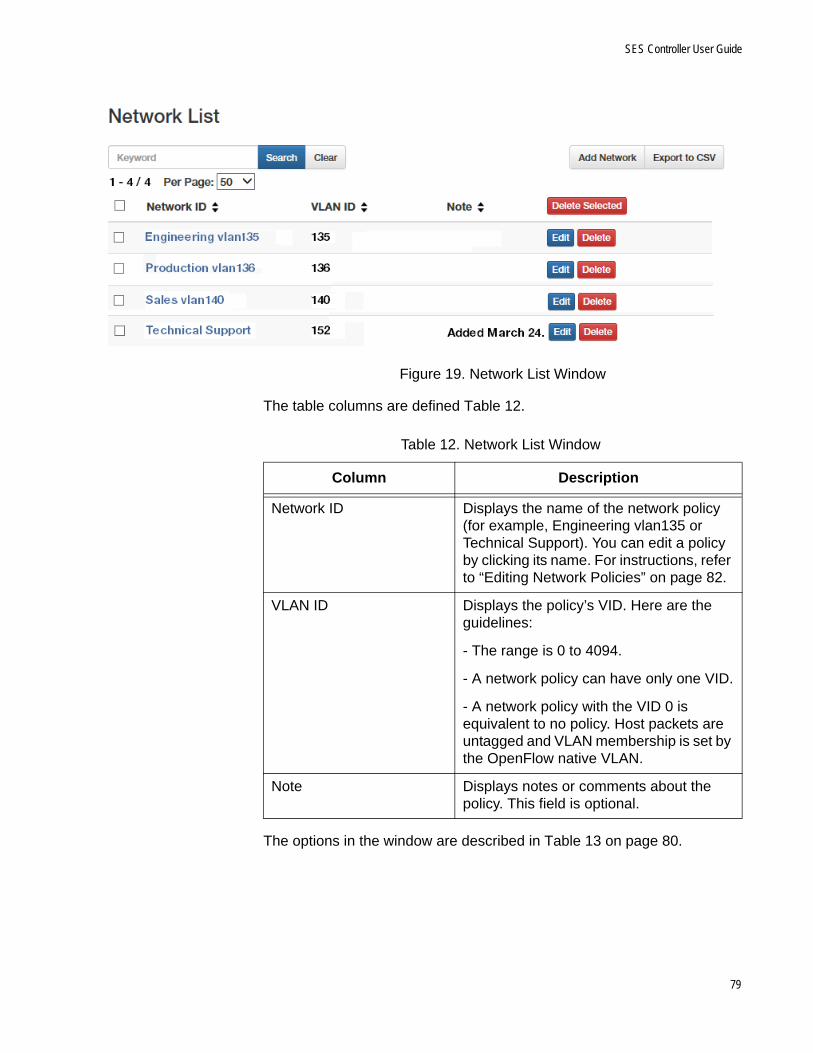
SES Controller User Guide
Figure 19. Network List Window
The table columns are defined Table 12.
The options in the window are described in Table 13 on page 80.
Table 12. Network List Window
Column Description
Network ID Displays the name of the network policy (for example, Engineering vlan135 or Technical Support). You can edit a policy by clicking its name. For instructions, refer to “Editing Network Policies” on page 82.
VLAN ID Displays the policy’s VID. Here are the guidelines:
- The range is 0 to 4094.
- A network policy can have only one VID.
- A network policy with the VID 0 is equivalent to no policy. Host packets are untagged and VLAN membership is set by the OpenFlow native VLAN.
Note Displays notes or comments about the policy. This field is optional.
79

Chapter 4: Network, Location, and Schedule Policies
Adding NetworkPolicies
This section contains the procedure for adding new network policies to the SES controller. The policies define the VLAN memberships of hosts on switch ports under OpenFlow management. For background information, refer to “Network Policies” on page 77.
To add a new network policy, perform the following procedure:
1. Select Policy Settings -> Add Network.
The Add Network window is shown in Figure 20 on page 81.
Table 13. Options in the Network List Window
Option Description
Search field and button Use the Search field and button to search the table for a specific policy. Here are search guidelines:
- Searches are case sensitive.
- Searches include all table columns.
Clear button Use this button to clear the Search field and redisplay the entire list of policies.
Add Network Button Use this button to add a new network policy. For directions, go to “Adding Network Policies” on page 80.
Delete Selected button Use this button to delete multiple network policies from the SES controller, simultaneously. For instructions, refer to “Deleting Network Policies” on page 83.
Edit button Use this button to edit network policies. For instructions, refer to “Editing Network Policies” on page 82.
Delete button Use this button to delete a single policy from the SES controller. For instructions, refer to “Deleting Network Policies” on page 83.
Export to CVS button Use this button to export the table in the window as a CVS file to your computer. After clicking the button, follow the prompts.
80

SES Controller User Guide
Figure 20. Add Network Window
2. Fill in the fields. Refer to Table 14.
3. After filling in the fields, click the Submit button to add the new network policy or the Cancel button to cancel the procedure.
At this point the new network policy is not assigned to any hosts.
Table 14. Add Network Window
Column Description
Network ID Enter a unique name for the new network policy (for example, Engineering vlan135 or Technical Support). The name can be up to 255 characters. Spaces and special characters are allowed.
VLAN ID Enter a VID for the network policy. Here are the guidelines:
- The range is 0 to 4094.
- A network policy can have only one VID.
- A network policy with the VID 0 is equivalent to no policy. Host packets are untagged and VLAN membership is set by the OpenFlow native VLAN.
- Different network policies can have the same VID.
Note Enter notes or comments about the network. The note can be up to 255 characters. Spaces are allowed, but no special characters. This parameter is optional.
81

Chapter 4: Network, Location, and Schedule Policies
4. To assign it to hosts, refer to “Adding Policy Devices” on page 119 or “Editing Policy Devices” on page 124.
Editing NetworkPolicies
You can edit the following network policy settings:
Name
VID
Note
NoteA change to the VID in a network policy assigned to policy devices is immediately transmitted to all OpenFlow switches with hosts of the policy. VLAN memberships of hosts are changed to the new VID.
To edit a network policy, perform the following procedure:
1. Select Policy Settings -> Network List.
The SES controller displays the Network List window. Refer to Figure 19 on page 79
2. Click the Edit button in the right column of the network policy you want to edit. You can edit only one policy at a time.
The SES controller displays the Modify Network window, with the parameter settings of the selected policy. An example is shown in Figure 21.
Figure 21. Modify Network Window
3. Edit the parameter settings. The parameters are defined in Table 14 on page 81.
4. After editing the fields, click the Submit button to add your changes to the network policy or the Cancel button to cancel the procedure.
82
SES Controller User Guide
Deleting NetworkPolicies
This section contains the procedure for deleting network policies from the SES controller.
NoteYou cannot delete network policies while they are assigned to policy devices. You must either edit the policy devices to remove the network policies or delete the policy devices. For instructions, refer to “Editing Policy Devices” on page 124 or “Deleting Policy Devices” on page 127.
To delete network policies from the SES controller, perform the following procedure:
1. Select Policy Settings -> Network List.
The SES controller displays the Network List window. Refer to Figure 19 on page 79.
2. Do one of the following:
To delete a single policy, click its Delete button in the right column of the table.
To delete multiple policies, click the check boxes in the left column of the policies and click the Delete Selected button above the right column.
The SES controller displays a confirmation prompt.
3. Click the OK button to delete the selected network policies or the Cancel button to cancel the procedure.
If you see the message “Failed to delete Network. Network is used,” the network policy cannot be deleted because it is currently assigned to a policy device. To delete the network policy, first remove it from the policy device or delete the policy device.
83

Chapter 4: Network, Location, and Schedule Policies
Location Policies
Location policies define the switches that hosts can use to access networks. The sections are listed here:
“Introduction to Location Policies” next
“Displaying Location Policies” on page 85
“Adding Location Policies” on page 87
“Editing Location Policies” on page 89
“Deleting Location Policies” on page 90
Introduction toLocation Policies
Location policies are used to enhance network security. They restrict network hosts to specified OpenFlow switches. Hosts with location policies are allowed to access networks only from switches defined in their policies and are denied access to all other switches. Here are the guidelines to location policies:
Location policies can reference more than one switch.
Switches are identified by their datapath IDs.
You can add only registered switches to location policies. To add unregistered switches, you first have to register them. For instructions, refer to “Registering Switches” on page 46.
To combine hosts with their location policies, add policy devices, as explained in Chapter 5, “Policy Devices” on page 99.
Hosts without location policies can access networks from any switch.
You can assign a location policy to more than one policy device.
In this example of a location policy, three hosts are restricted to two x510-52GTX switches. The MAC addresses of the hosts are listed here:
42:33:66:c5:14:3e - J. Jones
8a:3a:9b:21:6a:43 - A. Smith
56:89:1b:c8:d3:21 - T. Edwards
The datapath IDs of the two switches are listed here:
0000ecc5ef7a237a
0000ecc5ef76be3d
The general steps are given here and shown in Figure 22 on page 85:
1. Add a location policy with the datapath IDs of the switches. For instructions, refer to “Adding Location Policies” on page 87.
84

SES Controller User Guide
2. Add a policy device with the location policy and hosts. For instructions, refer to “Adding Policy Devices” on page 119.
Figure 22. Location Policy Example
DisplayingLocation Policies
To view the current location policies in the SES controller, select Policy Settings -> Location List to display the Location List window. An example is shown in Figure 23 on page 86.
LocationPolicy
PolicyDevice
Host MACAddresses
85

Chapter 4: Network, Location, and Schedule Policies
Figure 23. Location List Window
The table columns are defined in Table 15.
The options in the window are described in Table 16.
Table 15. Location List Window
Column Description
Location ID Displays the name of the location policy.
Note Displays notes or comments about the policy. The note can be up to 255 characters.
Number of Switches Displays the number of OpenFlow switches in the location policy. To view the switches, click the name of the policy or the Edit button.
Table 16. Options in the Location List Window
Option Description
Search field and button Use the Search field and button to search the table for a specific policy. Here are the search guidelines:
- Searches are case sensitive.
- Searches include all table columns.
Clear button Use this button to clear the Search field and redisplay the entire list of policies.
Add Location Button Use this button to add new location policies. For directions, go to “Adding Location Policies” on page 87.
86

SES Controller User Guide
Adding LocationPolicies
This section contains the procedure for adding new location policies to the SES controller. To add a new location policy, perform the following procedure:
1. Select Policy Settings -> Add Location.
The Add Location window is shown in Figure 24.
Figure 24. Add Location Window
2. Click the Location ID field and enter a unique name for the new location policy. The name can be up to 255 characters. Spaces and special characters are allowed.
3. Click the Note field and enter a comment or description for the policy. This parameter is optional. The note can be up to 255 characters. Spaces and special characters are allowed.
Delete Selected button Use this button to delete multiple location policies from the SES controller, simultaneously. For instructions, refer to “Deleting Location Policies” on page 90.
Edit button Use this button to edit location policies. For instructions, refer to “Editing Location Policies” on page 89.
Delete button Use this button to delete a policy from the SES controller. For instructions, refer to “Deleting Location Policies” on page 90.
Export to CVS button Use this button to export the table in the window as a CVS file to your computer. After clicking the button, follow the prompts.
Table 16. Options in the Location List Window (Continued)
Option Description
87

Chapter 4: Network, Location, and Schedule Policies
4. Click the OpenFlow Switches Select button.
The SES controller displays the Select OpenFlow Switch window. It lists the registered OpenFlow switches. An example is shown in Figure 25.
Figure 25. Select OpenFlow Switch Window
5. Click the check boxes of the OpenFlow switches to be added to the new location policy. A location policy can have more than one switch and a switch can belong to more than one location policy.
6. Click the Submit button to add the switches to the new location policy.
Figure 26 is an example of a completed location policy.
Figure 26. Completed Location Policy
7. Click the Submit button to add the new location policy or the Cancel button to cancel the procedure.
8. To assign the location policy to a policy device, refer to “Adding Policy Devices” on page 119 or “Editing Policy Devices” on page 124.
88

SES Controller User Guide
Editing LocationPolicies
This section contains the procedure for editing location policies. Here are the guidelines:
You can edit the name or description of a policy, as well as add or remove registered OpenFlow switches.
You can edit location policies while they are attached to policy devices.
NoteIf a location policy is already assigned to a policy device, any changes to its list of switches are transmitted by the SES controller to the switches.
Caution
Exercise caution when deleting switches from location policies. Hosts that are actively using deleted switches in their location policies to access networks might lose network connectivity.
To edit the settings of a location policy, perform the following procedure:
1. Select Policy Settings -> Location List.
The SES controller displays the Location List window. Refer to Figure 23 on page 86.
2. Click the Edit button of the name of the location policy you want to edit. You can edit only one policy at a time.
The SES controller displays the Modify Location window with the properties of the selected policy. An example is shown in Figure 27.
Figure 27. Modify Location Window
89

Chapter 4: Network, Location, and Schedule Policies
3. To edit the Location ID field, click the field and edit the name. The name must be unique from all other location policy names. It can be up to 255 characters. Spaces and special characters are allowed.
4. To edit the Note field, click it and enter a comment or description. This parameter is optional. It can be up to 255 characters. Spaces and special characters are allowed.
5. To add or remove switches, click the OpenFlow Switches Select button.
The SES controller displays the Select OpenFlow Switch window, listing all the registered OpenFlow switches in the controller. Switches with check marks in the check boxes in the left column are already members of a location policy. An example is shown in Figure 25 on page 88.
6. To add or remove switches, click the check boxes in the left column. Switches that are already members of a location policy have check marks in their check boxes. Location policies can have more than one switch and switches can belong to more than one location policy.
7. Click the Submit button in the Select OpenFlow Switch window to implement your changes to the list of member switches in the location policy.
Figure 26 on page 88 is an example of a completed location policy.
8. Click the Submit button to implement your changes to the location policy or the Cancel button to cancel the procedure.
Deleting LocationPolicies
This section contains the procedure for deleting location policies from the SES controller.
NoteYou cannot delete location policies while they are assigned to policy devices. You must first either edit the policy devices to remove the location policies or delete the policy devices. For instructions, refer to “Editing Policy Devices” on page 124 or “Deleting Policy Devices” on page 127.
To delete location policies, perform the following procedure:
1. Select Policy Settings -> Location List.
The SES controller displays the Location List window. Refer to Figure 23 on page 86.
2. Do one of the following:
90
SES Controller User Guide
To delete a single policy, click its Delete button in the right column of the table.
To delete multiple policies, click the check boxes in the left column of the policies and then click the Delete Selected button above the right column.
The SES controller displays a confirmation prompt.
3. Click the OK button to delete the selected location policies or the Cancel button to cancel the procedure.
If you see the message “Failed to delete Location. Location is used,” the SES controller cannot delete the location policy because it is currently part of a policy device. To delete the policy, first remove it from the policy device or delete the policy device.
91

Chapter 4: Network, Location, and Schedule Policies
Schedule Policies
You use schedule policies to limit the days or times when hosts can access your network. The feature is explained in the following sections
“Introduction to Schedule Policies” next
“Displaying Schedule Policies” on page 93
“Adding Schedule Policies” on page 95
“Editing Schedules Policies” on page 97
“Deleting Schedule Policies” on page 98
Introduction toSchedule Policies
Schedule policies are used to define the days and times when hosts can access networks. Hosts accessing networks during days or times not included in their schedule policies are blocked by OpenFlow switches. Here are the guidelines to schedule policies:
A schedule policy can specify a block of time spanning minutes, hours, days, weeks, or months.
You assign schedule polices to hosts with policy devices. For instructions, refer to Chapter 5, “Policy Devices” on page 99.
A schedule policy can specify only one block of time. However, policy devices can have multiple schedule policies. For an example, refer to Figure 38 on page 106.
Hosts that do not have schedule policies can access networks at any time.
In this example of a schedule policy, three hosts are allowed access to a network from September 7 at 8 a.m. to September 10 at 5:30 p.m. The MAC addresses of the hosts are listed here:
a3:33:66:c5:14:3e - J. Jones
4e:3a:9b:21:6a:43 - A. Smith
56:89:1b:c8:d3:21 - T. Edwards
The general steps are listed here and shown in Figure 28 on page 93:
1. Add a schedule policy containing the start date and time 2017-09-07 and 08:00:00, and end date and time 2017-09-10 and 17:30:00. For instructions, refer to “Adding Schedule Policies” on page 95.
2. Add a policy device containing the host MAC addresses and schedule policy. For instructions, refer to “Adding Policy Devices” on page 119.
92
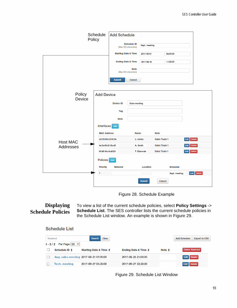
SES Controller User Guide
Figure 28. Schedule Example
DisplayingSchedule Policies
To view a list of the current schedule policies, select Policy Settings -> Schedule List. The SES controller lists the current schedule policies in the Schedule List window. An example is shown in Figure 29.
Figure 29. Schedule List Window
SchedulePolicy
PolicyDevice
Host MACAddresses
93
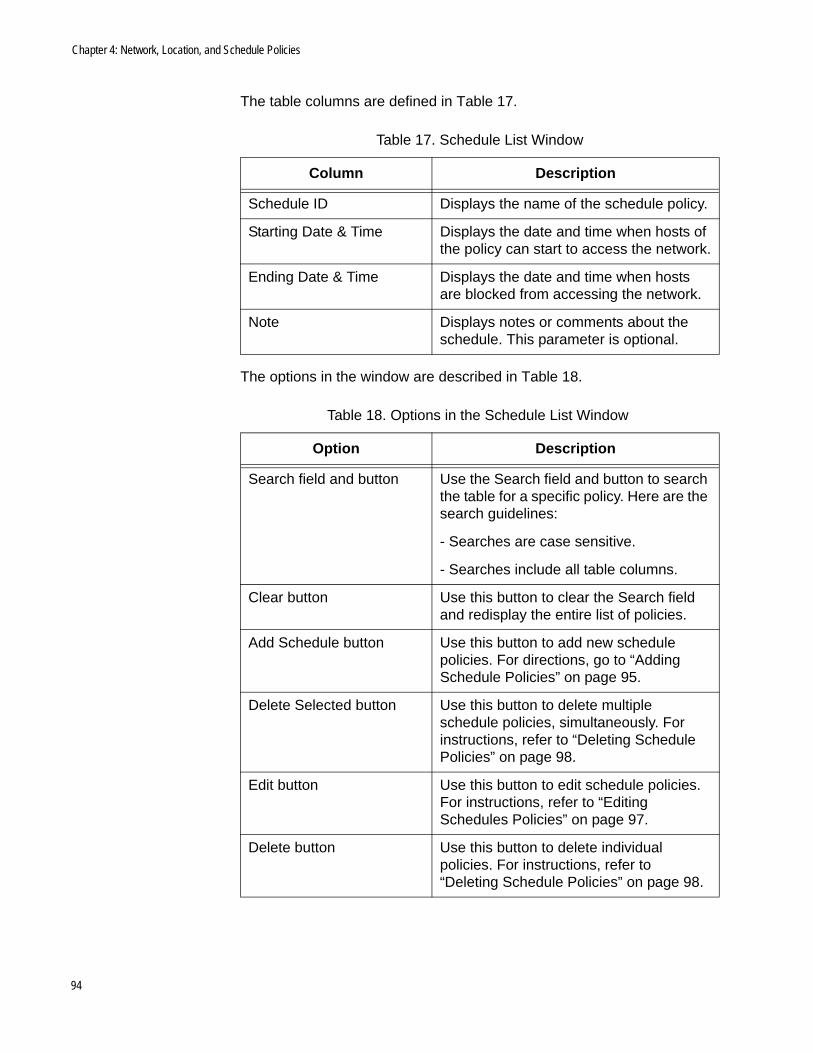
Chapter 4: Network, Location, and Schedule Policies
The table columns are defined in Table 17.
The options in the window are described in Table 18.
Table 17. Schedule List Window
Column Description
Schedule ID Displays the name of the schedule policy.
Starting Date & Time Displays the date and time when hosts of the policy can start to access the network.
Ending Date & Time Displays the date and time when hosts are blocked from accessing the network.
Note Displays notes or comments about the schedule. This parameter is optional.
Table 18. Options in the Schedule List Window
Option Description
Search field and button Use the Search field and button to search the table for a specific policy. Here are the search guidelines:
- Searches are case sensitive.
- Searches include all table columns.
Clear button Use this button to clear the Search field and redisplay the entire list of policies.
Add Schedule button Use this button to add new schedule policies. For directions, go to “Adding Schedule Policies” on page 95.
Delete Selected button Use this button to delete multiple schedule policies, simultaneously. For instructions, refer to “Deleting Schedule Policies” on page 98.
Edit button Use this button to edit schedule policies. For instructions, refer to “Editing Schedules Policies” on page 97.
Delete button Use this button to delete individual policies. For instructions, refer to “Deleting Schedule Policies” on page 98.
94
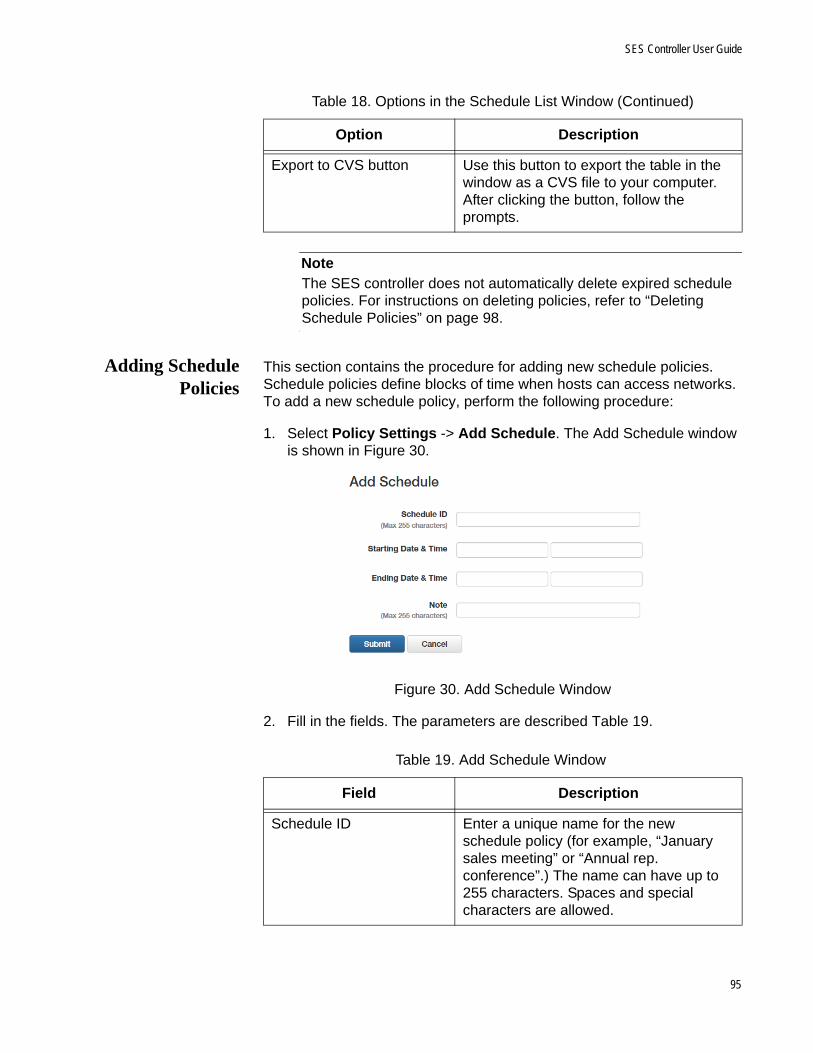
SES Controller User Guide
NoteThe SES controller does not automatically delete expired schedule policies. For instructions on deleting policies, refer to “Deleting Schedule Policies” on page 98.
Adding SchedulePolicies
This section contains the procedure for adding new schedule policies. Schedule policies define blocks of time when hosts can access networks. To add a new schedule policy, perform the following procedure:
1. Select Policy Settings -> Add Schedule. The Add Schedule window is shown in Figure 30.
Figure 30. Add Schedule Window
2. Fill in the fields. The parameters are described Table 19.
Export to CVS button Use this button to export the table in the window as a CVS file to your computer. After clicking the button, follow the prompts.
Table 18. Options in the Schedule List Window (Continued)
Option Description
Table 19. Add Schedule Window
Field Description
Schedule ID Enter a unique name for the new schedule policy (for example, “January sales meeting” or “Annual rep. conference”.) The name can have up to 255 characters. Spaces and special characters are allowed.
95
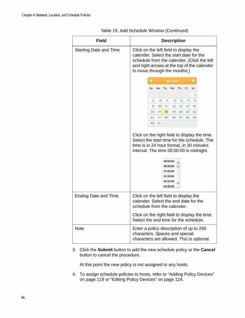
Chapter 4: Network, Location, and Schedule Policies
3. Click the Submit button to add the new schedule policy or the Cancel button to cancel the procedure.
At this point the new policy is not assigned to any hosts.
4. To assign schedule policies to hosts, refer to “Adding Policy Devices” on page 119 or “Editing Policy Devices” on page 124.
Starting Date and Time Click on the left field to display the calender. Select the start date for the schedule from the calender. (Click the left and right arrows at the top of the calender to move through the months.)
Click on the right field to display the time. Select the start time for the schedule. The time is in 24 hour format, in 30 minutes interval. The time 00:00:00 is midnight.
Ending Date and Time Click on the left field to display the calender. Select the end date for the schedule from the calender.
Click on the right field to display the time. Select the end time for the schedule.
Note Enter a policy description of up to 255 characters. Spaces and special characters are allowed. This is optional.
Table 19. Add Schedule Window (Continued)
Field Description
96

SES Controller User Guide
Editing SchedulesPolicies
This section contains the procedure for editing schedule policies. Here are the guidelines:
You can edit the name, description, or start or end dates of a policy
You can edit schedule policies while they are assigned to policy devices.
NoteChanges to the start or end date or time of a schedule that is already assigned to a policy device are immediately transmitted by the SES controller to the switches.
Caution
Exercise caution when modifying schedules that hosts are actively using to access networks. Hosts may lose network connectivity if they are in violation of new start or end dates or times.
To edit the settings of a schedule policy, perform the following procedure:
1. Select Policy Settings -> Schedule List.
The SES controller displays the Schedule List window. Refer to Figure 29 on page 93.
2. Click the Edit button or the name of the schedule policy you want to edit. You can edit only one policy at a time.
The SES controller displays the Modify Schedule window with the parameter settings of the selected policy. An example is shown in Figure 31.
Figure 31. Modify Schedule Window
97
Chapter 4: Network, Location, and Schedule Policies
3. Edit the parameter settings. The parameters are defined in Table 17 on page 94.
4. After editing the fields, click the Submit button to add your changes to the schedule policy or the Cancel button to cancel the procedure.
Deleting SchedulePolicies
This section contains the procedure for deleting schedule policies from the SES controller.
NoteYou cannot delete schedule policies while they are assigned to policy devices. You must first either edit the policy devices to remove the schedule policies or delete the policy devices. For instructions, refer to “Editing Policy Devices” on page 124 or “Deleting Policy Devices” on page 127.
NoteThe SES controller does not automatically delete expired schedule policies.
To delete schedule policies from the controller, perform the following procedure:
1. Select Policy Settings -> Schedule List.
The SES controller displays the Schedule List window. Refer to Figure 29 on page 93.
2. Do one of the following:
To delete a single policy, click its Delete button in the right column.
To delete multiple policies, click the check boxes In the left column of the policies to be deleted and then click the Delete Selected button.
The SES controller displays a confirmation prompt.
3. Click the OK button to delete the selected policies or the Cancel button to cancel the procedure.
If you see the message “Failed to delete Schedule. Schedule is used,” you cannot delete the schedule policy because it is assigned to a policy device. To delete it, first remove it from its policy device or delete the policy device.
98
Chapter 5
Policy Devices
This chapter includes the following sections:
“Introduction to Policy Devices” on page 100
“Displaying Policy Devices” on page 110
“Displaying Active Hosts and Policy Devices” on page 113
“Adding Policy Devices” on page 119
“Editing Policy Devices” on page 124
“Deleting Policy Devices” on page 127
99

Chapter 5: Policy Devices
Introduction to Policy Devices
After the SES controller has learned the hosts in your network and you have added the appropriate network, location, and schedule policies, you have to combine them together. That is the purpose of policy devices. They contain hosts and their respective policies, Once assigned to policy devices, hosts adhere to the policies. They become members of the VLANs in the network policies and are allowed to access networks according to the restrictions in their location and schedule policies.
You add policy devices with the Add Device window, shown in Figure 32. The main parts of the window are listed here:
Description - The fields at the top are used to name policy devices and to add information to assist in identifying them.
Hosts - This section contains the MAC addresses of hosts. A policy device can have multiple hosts.
Policy groups - This section contains the network, location, and schedule policies for the hosts. The policies are arranged in groups, A policy group can have up to three polices, one of each type. A policy device can have any number of policy groups. The example window has two policy groups.
Figure 32. Example Policy Device Window
Hosts
Policy Groups
Description
100
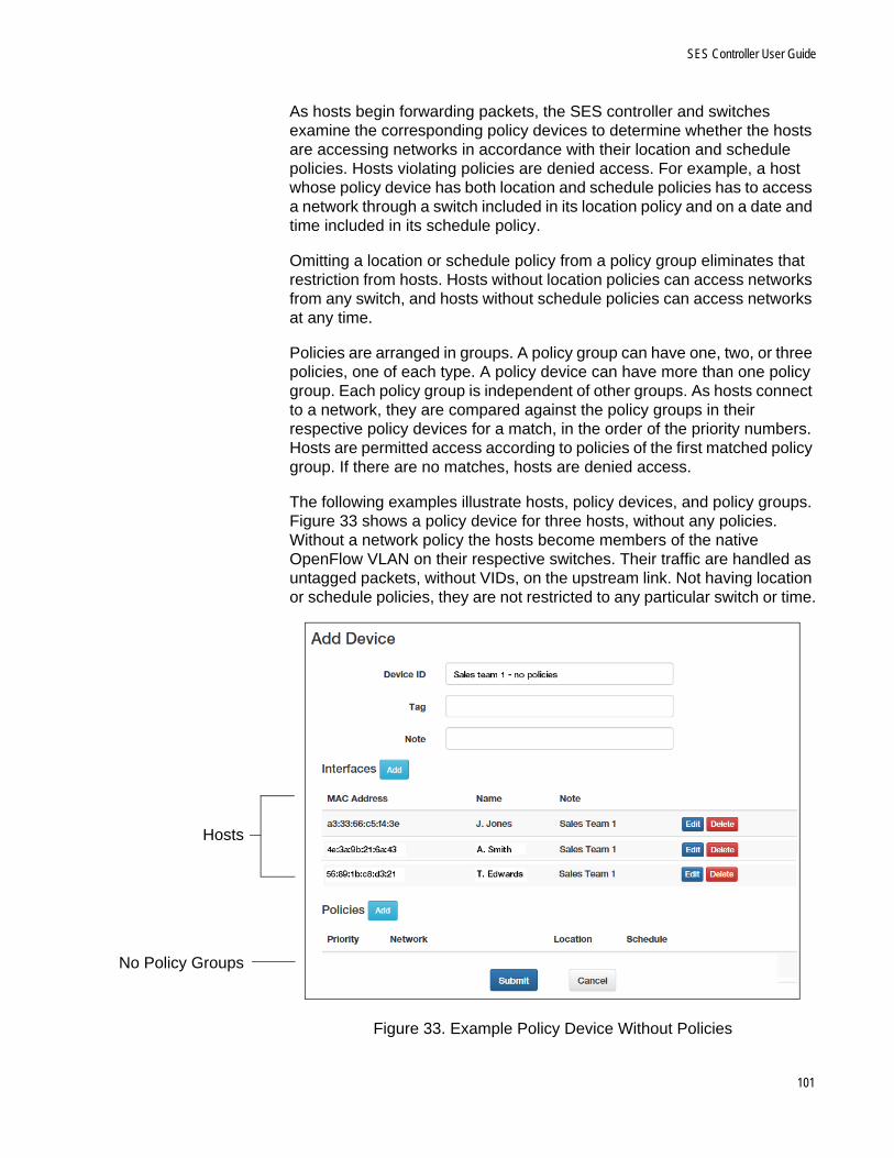
SES Controller User Guide
As hosts begin forwarding packets, the SES controller and switches examine the corresponding policy devices to determine whether the hosts are accessing networks in accordance with their location and schedule policies. Hosts violating policies are denied access. For example, a host whose policy device has both location and schedule policies has to access a network through a switch included in its location policy and on a date and time included in its schedule policy.
Omitting a location or schedule policy from a policy group eliminates that restriction from hosts. Hosts without location policies can access networks from any switch, and hosts without schedule policies can access networks at any time.
Policies are arranged in groups. A policy group can have one, two, or three policies, one of each type. A policy device can have more than one policy group. Each policy group is independent of other groups. As hosts connect to a network, they are compared against the policy groups in their respective policy devices for a match, in the order of the priority numbers. Hosts are permitted access according to policies of the first matched policy group. If there are no matches, hosts are denied access.
The following examples illustrate hosts, policy devices, and policy groups. Figure 33 shows a policy device for three hosts, without any policies. Without a network policy the hosts become members of the native OpenFlow VLAN on their respective switches. Their traffic are handled as untagged packets, without VIDs, on the upstream link. Not having location or schedule policies, they are not restricted to any particular switch or time.
Figure 33. Example Policy Device Without Policies
Hosts
No Policy Groups
101
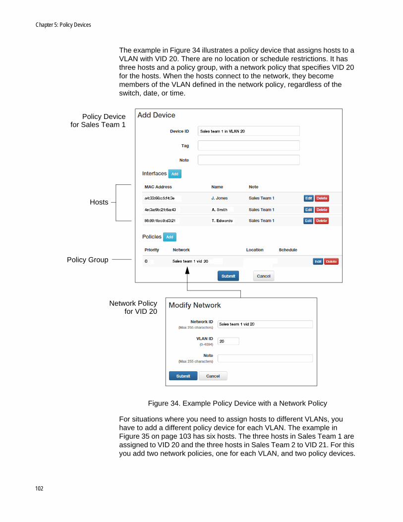
Chapter 5: Policy Devices
The example in Figure 34 illustrates a policy device that assigns hosts to a VLAN with VID 20. There are no location or schedule restrictions. It has three hosts and a policy group, with a network policy that specifies VID 20 for the hosts. When the hosts connect to the network, they become members of the VLAN defined in the network policy, regardless of the switch, date, or time.
Figure 34. Example Policy Device with a Network Policy
For situations where you need to assign hosts to different VLANs, you have to add a different policy device for each VLAN. The example in Figure 35 on page 103 has six hosts. The three hosts in Sales Team 1 are assigned to VID 20 and the three hosts in Sales Team 2 to VID 21. For this you add two network policies, one for each VLAN, and two policy devices.
Policy Devicefor Sales Team 1
Network Policyfor VID 20
Hosts
Policy Group
102

SES Controller User Guide
Figure 35. Example Policy Devices for Different VLAN Assignments
The next example in Figure 36 on page 104 adds a location policy to the policy device for Sales Team 1, to restrict the hosts to only those switches in the location policy. The switches block their ports if they attempt to
Policy Device forSales Team 1 and
VID 20
Policy Device forSales Team 2 and
VID 21
Network Policyfor VID 20
Network Policyfor VID 21
Policy Group
Policy Group
103
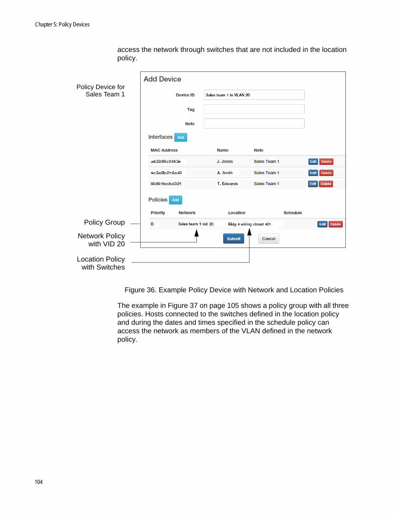
Chapter 5: Policy Devices
access the network through switches that are not included in the location policy.
Figure 36. Example Policy Device with Network and Location Policies
The example in Figure 37 on page 105 shows a policy group with all three policies. Hosts connected to the switches defined in the location policy and during the dates and times specified in the schedule policy can access the network as members of the VLAN defined in the network policy.
Network Policywith VID 20
Location Policywith Switches
Policy Device forSales Team 1
Policy Group
104

SES Controller User Guide
Figure 37. Example Policy Device with Network, Location, and Schedule Policies
The examples up to this point have had only one policy group, with one, two, or three policies. But there can be situations that require multiple policy groups in policy devices. One example is restricting network access to recurring dates and times, such as Monday to Friday, 9:00am to 5:00pm. Given that schedule policies can define blocks of time, not recurring time, this situation requires multiple policy groups with different schedule policies.
An example is shown in Figure 38 on page 106. Hosts are restricted to Monday to Friday, 9:00am to 5:00pm. The schedule policy for Monday is included in the illustration. As hosts connect to switches, the SES controller compares their actual connection dates and times with the schedule policies, and allows them to access the network when there is a match and denies access when there is no match.
Network Policywith VID 20
Location Policywith Switches
Policy Group
Schedule Policywith Dates and Times
105

Chapter 5: Policy Devices
Figure 38. Example Policy Device with Multiple Policy Groups and Schedules
For example, when hosts attach on Thursday at 9:00am, the SES controller determines that the actual connection date does not match the schedule policies in groups 1 to 3, but does match with group 4. Consequently, on that day it allows hosts to access the network during the
106

SES Controller User Guide
hours specified in that policy group.
The order in which the policy groups for the different weekdays are listed in the policy device is not important because the SES controller tests each policy group in sequence, starting with group 0, as hosts attach to a network.
You might also use multiple policy groups for hosts whose VLAN assignments need to change depending on the switches or times that they connect to the network. In the example in Figure 39, hosts are assigned to VID 20 when connecting to the switches in building 4 and VID 21 when using switches in building 5.
Figure 39. Example Policy Device with Multiple Policy Groups and Network Policies
Another situation where you might use multiple policy groups in a policy device is when two or more groups of hosts can be differentiated either with location or schedule policies. Here, you can add a different policy group for each host group.
Figure 40 on page 108 illustrates the concept. It has six hosts. Three hosts belong to sales team 1 in building 1 and three hosts belong to sales team 2 in building 2. The teams have different location policies to restrict them to the appropriate switches in their buildings. The teams can be in the same policy device because they can be differentiated by location policies.
107

Chapter 5: Policy Devices
Figure 40. Example Policy Device with Multiple Policy Groups for Different Hosts
As explained, each policy group in a policy device functions as an independent unit. The SES controller compares hosts against them in the order they are listed in a policy device. Consequently, you might experience unwanted results if you do not structure the policy groups correctly. For example, the policy device in Figure 41 on page 109 has two policy groups. The first policy group has only a network policy. Consequently, it will always be true for all hosts. No hosts will ever be compared against the second policy group.
108
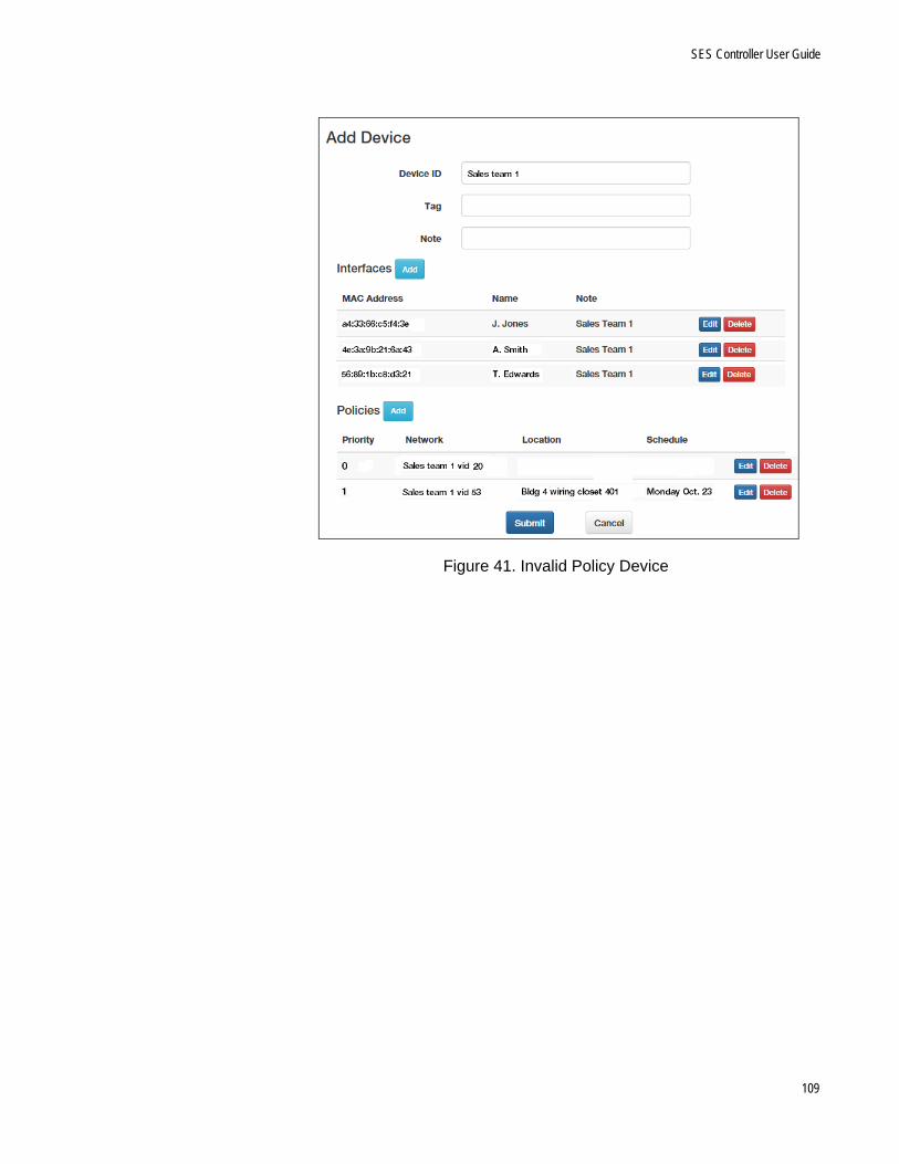
SES Controller User Guide
Figure 41. Invalid Policy Device
109

Chapter 5: Policy Devices
Displaying Policy Devices
This section explains the Device List window. The Device List window displays both active and inactive policy devices, as defined here:
Active policy devices have at least one active host. Hosts are considered active if switches can detect them. They do not have to be transmitting network traffic.
Inactive policy devices have no active hosts.
To view only active policy devices and their hosts, refer to “Displaying Active Hosts and Policy Devices” on page 113.
To view a list of all policy devices, select Device -> Device List. An example of the Device List window is shown in Figure 42.
Figure 42. Device List Window
The columns in the window are described in Table 20.
Table 20. Device List Window
Column Description
Device Displays the name of the policy device. To view or edit its settings, click its name. For instructions, refer to “Editing Policy Devices” on page 124.
Tag Displays the secondary name of the policy device. This field is optional.
Note Displays a description of the policy device. This field is optional.
110
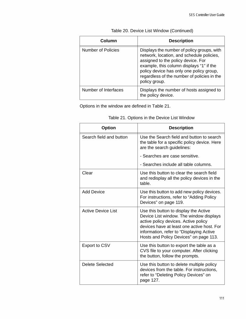
SES Controller User Guide
Options in the window are defined in Table 21.
Number of Policies Displays the number of policy groups, with network, location, and schedule policies, assigned to the policy device. For example, this column displays “1” if the policy device has only one policy group, regardless of the number of policies in the policy group.
Number of Interfaces Displays the number of hosts assigned to the policy device.
Table 21. Options in the Device List Window
Option Description
Search field and button Use the Search field and button to search the table for a specific policy device. Here are the search guidelines:
- Searches are case sensitive.
- Searches include all table columns.
Clear Use this button to clear the search field and redisplay all the policy devices in the table.
Add Device Use this button to add new policy devices. For instructions, refer to “Adding Policy Devices” on page 119.
Active Device List Use this button to display the Active Device List window. The window displays active policy devices. Active policy devices have at least one active host. For information, refer to “Displaying Active Hosts and Policy Devices” on page 113.
Export to CSV Use this button to export the table as a CVS file to your computer. After clicking the button, follow the prompts.
Delete Selected Use this button to delete multiple policy devices from the table. For instructions, refer to “Deleting Policy Devices” on page 127.
Table 20. Device List Window (Continued)
Column Description
111
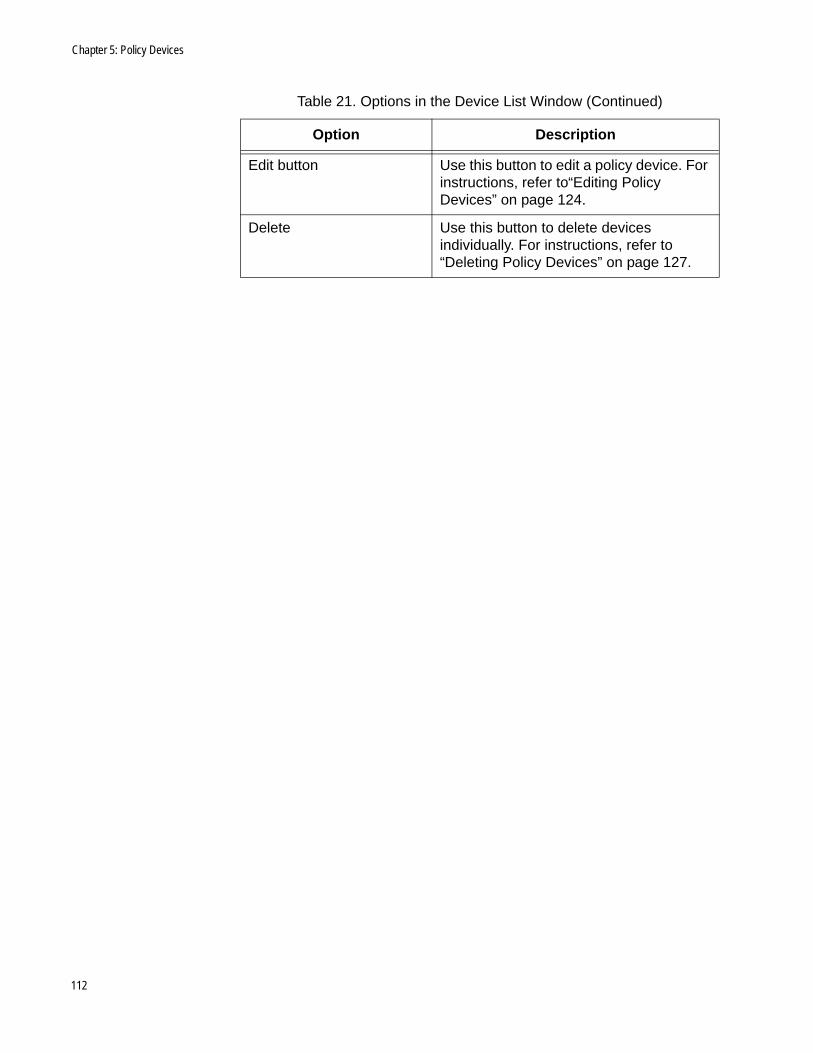
Chapter 5: Policy Devices
Edit button Use this button to edit a policy device. For instructions, refer to“Editing Policy Devices” on page 124.
Delete Use this button to delete devices individually. For instructions, refer to “Deleting Policy Devices” on page 127.
Table 21. Options in the Device List Window (Continued)
Option Description
112
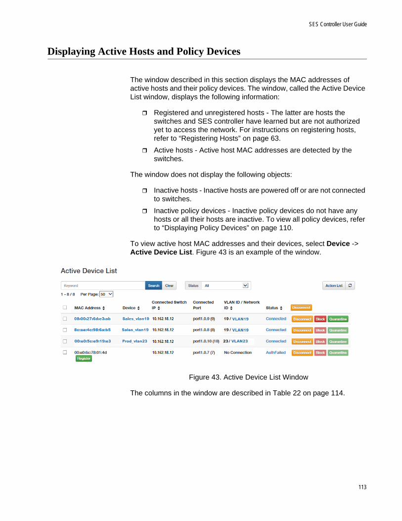
SES Controller User Guide
Displaying Active Hosts and Policy Devices
The window described in this section displays the MAC addresses of active hosts and their policy devices. The window, called the Active Device List window, displays the following information:
Registered and unregistered hosts - The latter are hosts the switches and SES controller have learned but are not authorized yet to access the network. For instructions on registering hosts, refer to “Registering Hosts” on page 63.
Active hosts - Active host MAC addresses are detected by the switches.
The window does not display the following objects:
Inactive hosts - Inactive hosts are powered off or are not connected to switches.
Inactive policy devices - Inactive policy devices do not have any hosts or all their hosts are inactive. To view all policy devices, refer to “Displaying Policy Devices” on page 110.
To view active host MAC addresses and their devices, select Device -> Active Device List. Figure 43 is an example of the window.
Figure 43. Active Device List Window
The columns in the window are described in Table 22 on page 114.
113
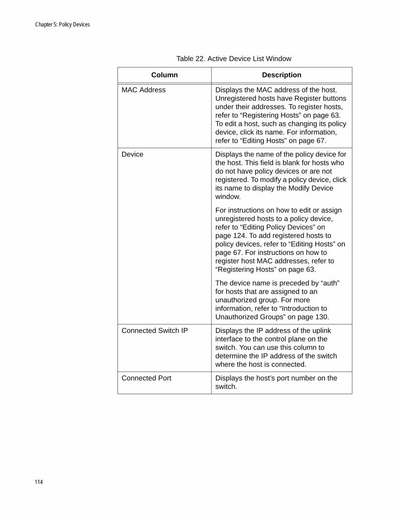
Chapter 5: Policy Devices
Table 22. Active Device List Window
Column Description
MAC Address Displays the MAC address of the host. Unregistered hosts have Register buttons under their addresses. To register hosts, refer to “Registering Hosts” on page 63. To edit a host, such as changing its policy device, click its name. For information, refer to “Editing Hosts” on page 67.
Device Displays the name of the policy device for the host. This field is blank for hosts who do not have policy devices or are not registered. To modify a policy device, click its name to display the Modify Device window.
For instructions on how to edit or assign unregistered hosts to a policy device, refer to “Editing Policy Devices” on page 124. To add registered hosts to policy devices, refer to “Editing Hosts” on page 67. For instructions on how to register host MAC addresses, refer to “Registering Hosts” on page 63.
The device name is preceded by “auth” for hosts that are assigned to an unauthorized group. For more information, refer to “Introduction to Unauthorized Groups” on page 130.
Connected Switch IP Displays the IP address of the uplink interface to the control plane on the switch. You can use this column to determine the IP address of the switch where the host is connected.
Connected Port Displays the host’s port number on the switch.
114

SES Controller User Guide
VLAN ID / Network ID Displays the VLAN ID status of the host. The possible states are listed here:
- VID / network policy name: The host has a network policy, The VID in the policy is shown first followed by the policy name. To edit a policy, click its name. For instructions, refer to “Editing Network Policies” on page 82.
- Untagged: The host does not have a network policy and so does not have a VID. Its traffic is assigned to the OpenFlow native VLAN and is transmitted on the upstream interface as untagged packets, without a VID.
- No Connection: The host is not authorized to forward traffic through the network. Possible causes are the host is not registered or the switch port is disconnected or blocked.
Table 22. Active Device List Window (Continued)
Column Description
115

Chapter 5: Policy Devices
Options in the window are defined in Table 23.
Status Displays the host status. The possible states are listed here:
- Connected: The host is authorized to access the network and is currently connected to the network.
- Blocked: The host is blocked from accessing the network.
- Quarantined: The host has been assigned the VID of the quarantine VLAN.
- Rejected: The host is blocked from accessing the network and the switch port is shutdown.
- AuthFailed: The host is not registered or has violated a location or schedule policy and is prohibited from accessing the network.
For instructions on how to isolate hosts, refer to “Isolating Hosts” on page 68. For instructions on how to restore isolated hosts, refer to “Viewing or Restoring Isolated Hosts” on page 70.
Table 23. Options in the Active Device List Window
Option Description
Register button Use this button to register MAC addresses to permit hosts to access the network. For instructions, refer to “Registering Hosts” on page 63.
Search field and button Use the Search field and button to search the table for a specific device. Here are the search guidelines:
- Searches are case sensitive.
- Searches include all table columns.
Clear Use this button to clear the search field and redisplay all the devices in the table.
Table 22. Active Device List Window (Continued)
Column Description
116
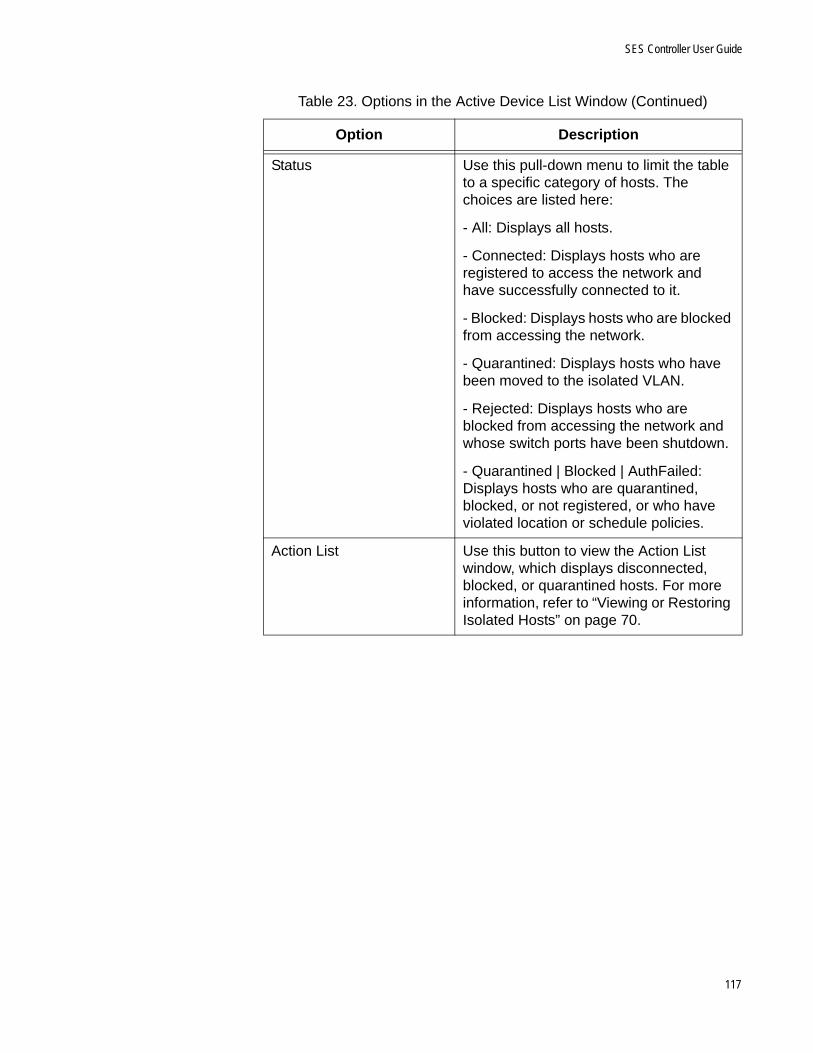
SES Controller User Guide
Status Use this pull-down menu to limit the table to a specific category of hosts. The choices are listed here:
- All: Displays all hosts.
- Connected: Displays hosts who are registered to access the network and have successfully connected to it.
- Blocked: Displays hosts who are blocked from accessing the network.
- Quarantined: Displays hosts who have been moved to the isolated VLAN.
- Rejected: Displays hosts who are blocked from accessing the network and whose switch ports have been shutdown.
- Quarantined | Blocked | AuthFailed: Displays hosts who are quarantined, blocked, or not registered, or who have violated location or schedule policies.
Action List Use this button to view the Action List window, which displays disconnected, blocked, or quarantined hosts. For more information, refer to “Viewing or Restoring Isolated Hosts” on page 70.
Table 23. Options in the Active Device List Window (Continued)
Option Description
117

Chapter 5: Policy Devices
Disconnect, Block, and Quarantine buttons
Use the buttons to stop hosts from accessing your network or to move them to the quarantine VLAN. The buttons are described here:
Disconnect - Shuts down the host’s OpenFlow port on the switch, interrupting the link between the switch and host.
Block - Blocks the host’s port from forwarding the host’s traffic, but the port remains up.
Quarantine - Changes the host’s VID to the quarantine VLAN. For instructions on setting the quarantine VID, refer to “Configuring the OpenFlow SES Controller Settings” on page 170.
For instructions on isolating hosts, refer to “Isolating Hosts” on page 68. To restore isolated hosts, refer to “Viewing or Restoring Isolated Hosts” on page 70.
Table 23. Options in the Active Device List Window (Continued)
Option Description
118

SES Controller User Guide
Adding Policy Devices
This section contains the procedure for adding new policy devices to the SES controller. Policy devices combine host MAC addresses with their respective network, location, or schedule policies. For background information, refer to “Introduction to Policy Devices” on page 100. Here are policy device guidelines:
Policy devices can have more than one host MAC address.
They can have more than one policy group.
They become active as soon as you add them to the SES controller.
You cannot add registered host MAC addresses to a new policy device with this procedure. For this, add a policy device without the registered MAC addresses and then edit the settings of the MAC addresses to add them to the policy device. For instructions, refer to “Editing Hosts” on page 67.
To add a policy device to the SES controller, perform the following procedure:
1. Select Device - > Add Device.
The SES controller displays the Add Device window. Refer to Figure 44.
Figure 44. Add Device Window
119

Chapter 5: Policy Devices
2. Fill in the Device ID, Tag, and Note fields. Refer to Table 24.
3. To add hosts to the device, do the following:
NoteYou cannot use this procedure to add registered host MAC addresses to a new policy device. Instead, add the policy device without the registered host MAC addresses. Afterwards, modify the properties of the host MAC addresses by adding the policy device to them. For instructions, refer to “Editing Hosts” on page 67.
a. Click the Interfaces Add button.
The SES controller displays the Edit Interface window. Refer to Figure 45.
Figure 45. Edit Interface Window
b. Fill in the fields. Refer to Table 25 on page 121.
Table 24. Add Device Window
Field Description
Device ID Enter a unique name for the policy device. A name can be up to 254 characters. Spaces and special characters are permitted. This field is required.
Tag Enter a secondary name for the device. The name can be up to 254 characters. Spaces and special characters are permitted. This field is optional.
Note Enter a policy description. This field is optional.
120
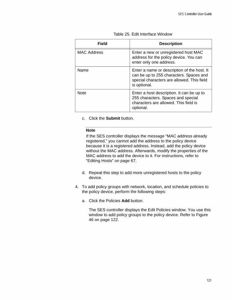
SES Controller User Guide
c. Click the Submit button.
NoteIf the SES controller displays the message “MAC address already registered,” you cannot add the address to the policy device because it is a registered address. Instead, add the policy device without the MAC address. Afterwards, modify the properties of the MAC address to add the device to it. For instructions, refer to “Editing Hosts” on page 67.
d. Repeat this step to add more unregistered hosts to the policy device.
4. To add policy groups with network, location, and schedule policies to the policy device, perform the following steps:
a. Click the Policies Add button.
The SES controller displays the Edit Policies window. You use this window to add policy groups to the policy device. Refer to Figure 46 on page 122.
Table 25. Edit Interface Window
Field Description
MAC Address Enter a new or unregistered host MAC address for the policy device. You can enter only one address.
Name Enter a name or description of the host. It can be up to 255 characters. Spaces and special characters are allowed. This field is optional.
Note Enter a host description. It can be up to 255 characters. Spaces and special characters are allowed. This field is optional.
121

Chapter 5: Policy Devices
Figure 46. Edit Policy Window
b. Fill in the fields. Refer to Table 26.
c. Click the Submit button.
d. To add more policy groups to the policy device, repeat this step.
5. After filling in the fields in the Add Device window, click the Submit button.
The new policy device is added to the SES controller. Unregistered hosts in policy devices cannot forward traffic through their respective
Table 26. Edit Policy Window
Field Description
Priority Enter a unique priority number for the policy group. The range is 0 to 255. The priority group can have only one priority number.
Network Use the pull-down menu to select a network policy for the device. You can select only one policy.
Location Use the pull-down menu to select a location policy for the device. You can select only one policy.
Schedule Use the pull-down menu to select a schedule policy for the device. You can select only one policy.
122

SES Controller User Guide
switches until you register their addresses. For instructions, refer to “Registering Hosts” on page 63.
6. To add registered host MAC addresses to the policy device, refer to “Editing Hosts” on page 67.
123
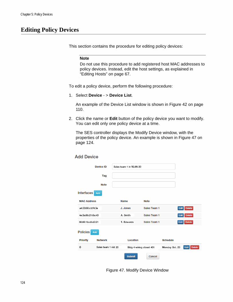
Chapter 5: Policy Devices
Editing Policy Devices
This section contains the procedure for editing policy devices:
NoteDo not use this procedure to add registered host MAC addresses to policy devices. Instead, edit the host settings, as explained in “Editing Hosts” on page 67.
To edit a policy device, perform the following procedure:
1. Select Device - > Device List.
An example of the Device List window is shown in Figure 42 on page 110.
2. Click the name or Edit button of the policy device you want to modify. You can edit only one policy device at a time.
The SES controller displays the Modify Device window, with the properties of the policy device. An example is shown in Figure 47 on page 124.
Figure 47. Modify Device Window
124
SES Controller User Guide
3. To add a new or unregistered host MAC address to the policy device, do the following:
a. Click the Interfaces Add button. The SES controller displays the Edit Interface window. Refer to Figure 45 on page 120.
b. Fill in the fields. Refer to Table 25 on page 121.
c. Click the Submit button.
NoteIf the SES controller displays the message “MAC address already registered,” you cannot add the host MAC address to the policy device because it is a registered address. To add a registered host MAC address, add the policy device without the host. Afterwards, add the policy device to the host, as explained in “Editing Hosts” on page 67.
d. Repeat this step to add more host MAC addresses. A policy device can have any number of hosts.
4. To delete a host, do the following:
a. Click the Delete button of the host MAC address you want to delete. You can delete only one host at a time.
The SES controller displays a confirmation prompt.
b. Click OK to delete the host or Cancel to cancel the procedure.
5. To add a policy group with network, location, or schedule policies to the policy device, do the following:
a. Click the Policies Add button. The SES controller displays the Edit Policies window. Refer to Figure 46 on page 122.
b. Fill in the fields. Refer to Table 26 on page 122.
c. Click the Submit button.
6. To edit a policy group, do the following:
a. Click the Edit button in the right column of the policy group. You can edit only one policy group at a time. The SES controller displays the Edit Policies window. Refer to Figure 46 on page 122.
b. Edit the fields. Refer to Table 26 on page 122.
c. Click the Submit button.
7. To delete a policy group, do the following:
125
Chapter 5: Policy Devices
a. Click the Delete button of the policy group you want to delete. You can delete only one policy group at a time.
The SES controller displays a confirmation prompt.
b. Click OK to delete the policy group or Cancel to cancel the procedure.
8. After modifying the policy device, click the Submit button to implement your changes or the Cancel button to cancel the procedure.
The SES controller sends your changes to the appropriate switches of the host.
126
SES Controller User Guide
Deleting Policy Devices
This section contains the procedure for deleting policy devices from the SES controller.
NoteDeleting a policy device with a network policy and active hosts causes the hosts to become members of the OpenFlow native VLAN.
To delete policy devices from the SES controller, perform the following procedure:
1. Select Device -> Device List.
The Device List window is shown in Figure 42 on page 110.
2. Do one of the following:
a. To delete a single policy device, click its Delete button in the right column.
b. To delete multiple policy devices, click their check boxes in the left column and then click the Delete Selected button in the upper right column.
The SES controller displays a confirmation prompt.
3. Click the OK button to delete the policy devices or the Cancel button to cancel the procedure.
If the deleted policy device had a policy group and active hosts, the hosts automatically become members of the OpenFlow native VLAN, until they are assigned to another policy device.
127

Chapter 5: Policy Devices
128
Chapter 6
Unauthorized Groups
This chapter includes the following sections:
“Introduction to Unauthorized Groups” on page 130
“Displaying Unauthorized Groups” on page 133
“Adding Unauthorized Groups” on page 135
“Editing Unauthorized Groups” on page 138
“Deleting Unauthorized Groups” on page 139
129

Chapter 6: Unauthorized Groups
Introduction to Unauthorized Groups
Hosts that violate location or schedule policies when accessing networks are designated as unauthorized hosts. The default action the SES controller performs in response to unauthorized hosts is block their ports, thereby denying them network access. You can, however, add a secondary policy level for hosts who violate their primary location or schedule policies. Instead of blocking host ports, switches can assign them to other VLANs. This is achieved with unauthorized groups.
Unauthorized groups define secondary policies for hosts who are denied network access because they violate either their primary location or schedule policy, or both. These secondary policies can redirect hosts to other VLANs or define other locations or schedules. The feature lets you grant network access to unauthorized hosts at possibly more restricted levels than might otherwise be provided by their primary policies.
An unauthorized group consists of a network policy and either a location or schedule policy, or both. The network policy contains the VID of a VLAN to which the SES controller redirects unauthorized hosts. The location and schedule policies define the violations and act as secondary policies.
When a host violates its primary location or schedule policy, the SES controller checks the unauthorized groups for a location or schedule policy that matches the violation. If it finds a matching policy, it assigns the host the VID in the network policy of the group.
As an example, if a host with a location policy attempts to access a switch with a datapath ID not included in its policy, the SES controller checks the unauthorized groups list for a location policy with a matching switch datapath ID. If the policy exists, the controller assigns the host to the VLAN in the network policy of the group and permits the host to access the network.
This is illustrated in Figure 48 on page 131. An unauthorized group redirects hosts to VID 56 on a switch with the datapath ID 0000ECCC5EF7A237A. The group applies to hosts that attempt to use the switch to access the network but whose location policies do not include the switch.
130

SES Controller User Guide
Figure 48. Example of an Unauthorized Group - 1
You can simplify unauthorized groups by adding empty location or schedule policies to cover all violations, rather than entering specific switches or times. This is illustrated in Figure 49 on page 132. The location policy does not contain any switch datapath IDs. Hosts connecting to any switch not in their primary location policies are directed to VID 56.
131

Chapter 6: Unauthorized Groups
Figure 49. Example of an Unauthorized Group - 2
Host policy management is dynamic. The SES controller and switches constantly monitor hosts to determine whether they are in compliance with their policies. Hosts that violate a policy, such as their scheduled time to access a switch, are immediately blocked, unless an unauthorized group grants them access.
132
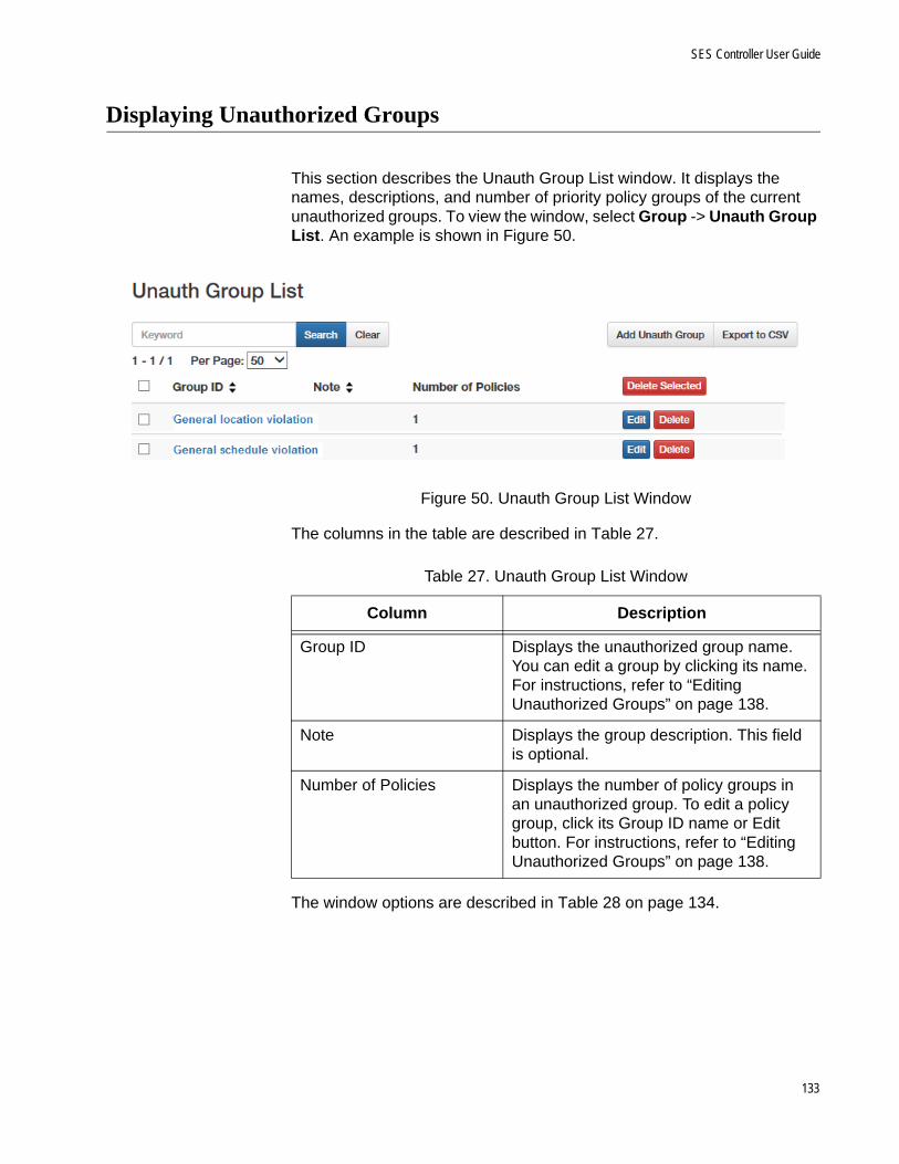
SES Controller User Guide
Displaying Unauthorized Groups
This section describes the Unauth Group List window. It displays the names, descriptions, and number of priority policy groups of the current unauthorized groups. To view the window, select Group -> Unauth Group List. An example is shown in Figure 50.
Figure 50. Unauth Group List Window
The columns in the table are described in Table 27.
The window options are described in Table 28 on page 134.
Table 27. Unauth Group List Window
Column Description
Group ID Displays the unauthorized group name. You can edit a group by clicking its name. For instructions, refer to “Editing Unauthorized Groups” on page 138.
Note Displays the group description. This field is optional.
Number of Policies Displays the number of policy groups in an unauthorized group. To edit a policy group, click its Group ID name or Edit button. For instructions, refer to “Editing Unauthorized Groups” on page 138.
133
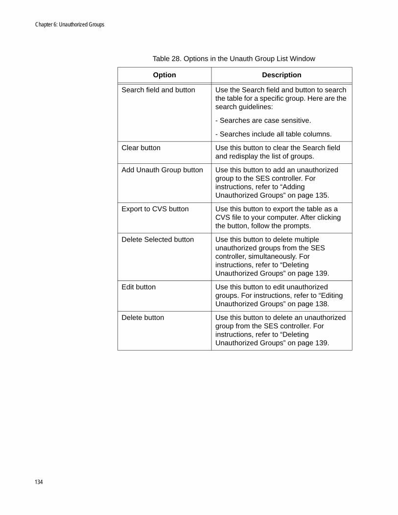
Chapter 6: Unauthorized Groups
Table 28. Options in the Unauth Group List Window
Option Description
Search field and button Use the Search field and button to search the table for a specific group. Here are the search guidelines:
- Searches are case sensitive.
- Searches include all table columns.
Clear button Use this button to clear the Search field and redisplay the list of groups.
Add Unauth Group button Use this button to add an unauthorized group to the SES controller. For instructions, refer to “Adding Unauthorized Groups” on page 135.
Export to CVS button Use this button to export the table as a CVS file to your computer. After clicking the button, follow the prompts.
Delete Selected button Use this button to delete multiple unauthorized groups from the SES controller, simultaneously. For instructions, refer to “Deleting Unauthorized Groups” on page 139.
Edit button Use this button to edit unauthorized groups. For instructions, refer to “Editing Unauthorized Groups” on page 138.
Delete button Use this button to delete an unauthorized group from the SES controller. For instructions, refer to “Deleting Unauthorized Groups” on page 139.
134
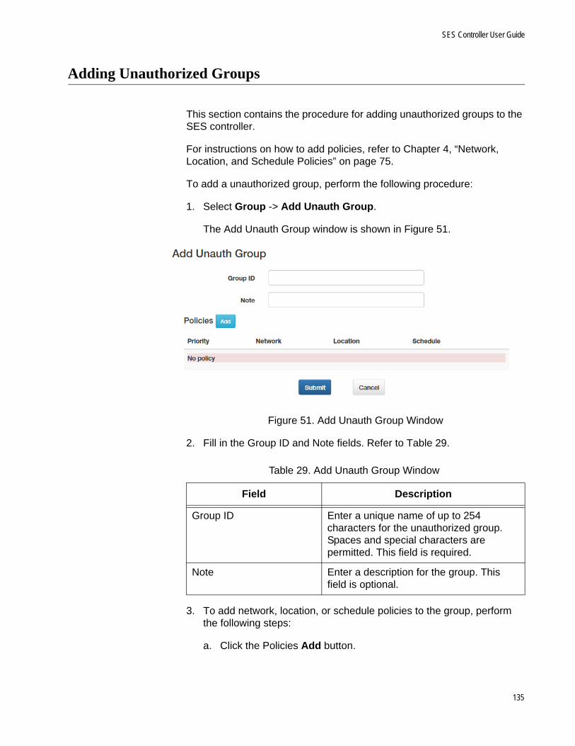
SES Controller User Guide
Adding Unauthorized Groups
This section contains the procedure for adding unauthorized groups to the SES controller.
For instructions on how to add policies, refer to Chapter 4, “Network, Location, and Schedule Policies” on page 75.
To add a unauthorized group, perform the following procedure:
1. Select Group -> Add Unauth Group.
The Add Unauth Group window is shown in Figure 51.
Figure 51. Add Unauth Group Window
2. Fill in the Group ID and Note fields. Refer to Table 29.
3. To add network, location, or schedule policies to the group, perform the following steps:
a. Click the Policies Add button.
Table 29. Add Unauth Group Window
Field Description
Group ID Enter a unique name of up to 254 characters for the unauthorized group. Spaces and special characters are permitted. This field is required.
Note Enter a description for the group. This field is optional.
135

Chapter 6: Unauthorized Groups
The SES controller displays the Edit Policies window. Refer to Figure 52.
Figure 52. Edit Policy Window
b. Fill in the fields. Refer to Table 30.
Table 30. Edit Policy Window
Field Description
Priority Enter a unique priority number for the policy group. The range is 0 to 255. The priority group can have only one priority number.
Network Use the pull-down menu to select a network policy for the group. You can select only one policy. Hosts who are violating a location or schedule policy are directed to the VID in this policy.
Location Use the pull-down menu to select a location policy that is to define a violation and act as a secondary policy. You can select only one policy. For background information, refer to “Introduction to Unauthorized Groups” on page 130.
Schedule Use the pull-down menu to select a schedule policy that is to define a violation and act as a secondary policy. You can select only one policy. For background information, refer to “Introduction to Unauthorized Groups” on page 130.
136

SES Controller User Guide
c. Click the Submit button.
d. To add more policies to the group, repeat this step.
4. Click the Submit button to add the new unauthorized group to the SES controller or the Cancel button to cancel the procedure.
When you click Submit, the SES controller adds the new group to the Unauth Group List window. New unauthorized groups are immediately active.
137
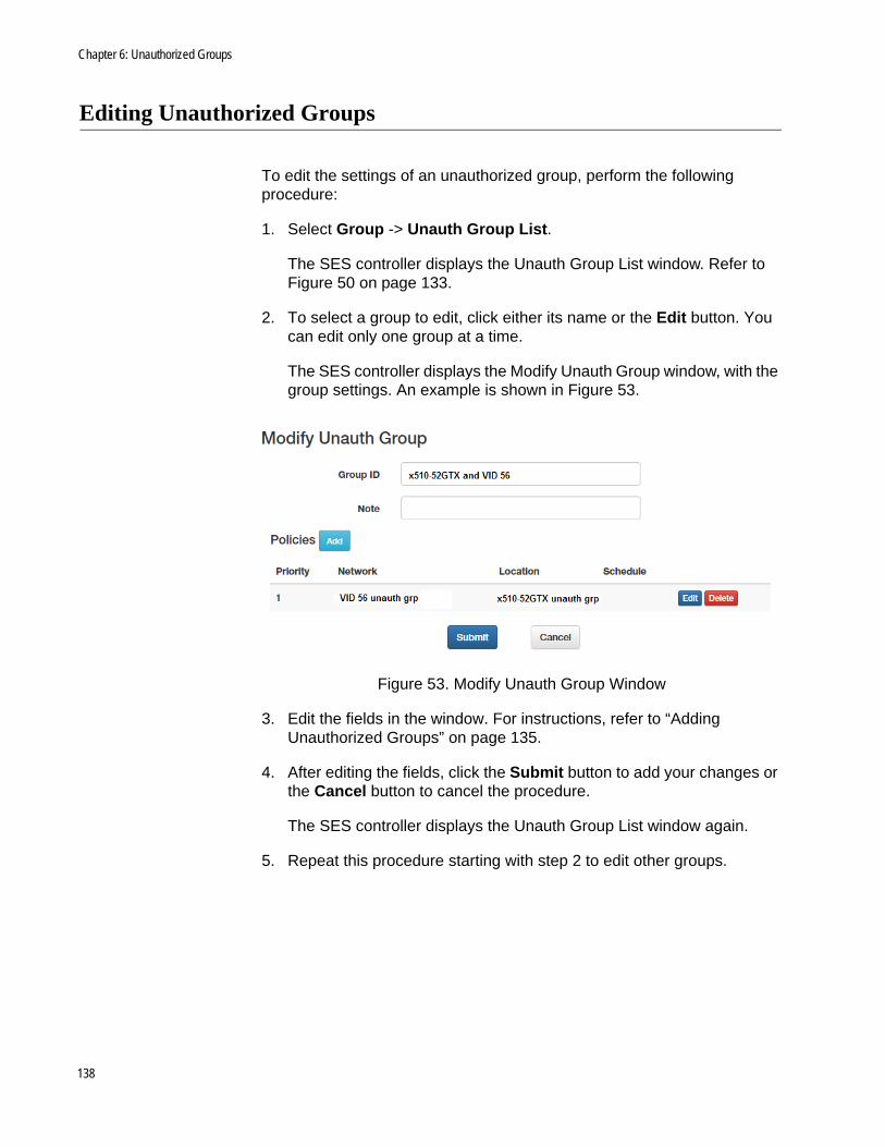
Chapter 6: Unauthorized Groups
Editing Unauthorized Groups
To edit the settings of an unauthorized group, perform the following procedure:
1. Select Group -> Unauth Group List.
The SES controller displays the Unauth Group List window. Refer to Figure 50 on page 133.
2. To select a group to edit, click either its name or the Edit button. You can edit only one group at a time.
The SES controller displays the Modify Unauth Group window, with the group settings. An example is shown in Figure 53.
Figure 53. Modify Unauth Group Window
3. Edit the fields in the window. For instructions, refer to “Adding Unauthorized Groups” on page 135.
4. After editing the fields, click the Submit button to add your changes or the Cancel button to cancel the procedure.
The SES controller displays the Unauth Group List window again.
5. Repeat this procedure starting with step 2 to edit other groups.
138
SES Controller User Guide
Deleting Unauthorized Groups
This section contains the procedure for deleting unauthorized groups from the SES controller.
NoteDeleting an unauthorized group immediately invalidates it. Hosts using it to access a network are immediately blocked by the SES controller and switches.
To delete unauthorized groups, perform the following procedure:
1. Select Groups -> Unauth Group List.
The SES controller displays the Unauth Group List window. Refer to Figure 50 on page 133
2. Do one of the following:
To delete a single group, click its Delete button in the right column of the table.
To delete multiple groups, click their check boxes in the left column and then click the Delete Selected button above the right column.
The SES controller displays a confirmation prompt.
3. Click the OK button to delete the group or the Cancel button to cancel the procedure.
139

Chapter 6: Unauthorized Groups
140

Chapter 7
System Settings
The chapter includes the following sections:
“Changing the Password” on page 142
“Changing the IPv4 Address of the SES Controller” on page 143
“Configuring Email Notifications” on page 146
“Configuring the Web Server” on page 150
“Setting the Date and Time” on page 154
“Backing Up or Restoring System Information” on page 157
“Backing Up or Restoring Authentication Information” on page 161
“Viewing Log Messages” on page 164
“Managing the SES Controller Licenses and Software” on page 167
“Configuring the OpenFlow SES Controller Settings” on page 170
“Downloading the Technical Support Information File” on page 173
“Restarting the SES Controller” on page 174
“Rebooting or Shutting Down the SES Controller’s Server” on page 175
“Uploading the Trap Monitoring Rule File” on page 176
“Configuring the Enhanced Firewall Protection Feature” on page 177
141

Chapter 7: System Settings
Changing the Password
The section contains the procedure for changing the login password on the SES controller.
NoteYou cannot change the “manager” username.
To change the login password, perform the following procedure:
1. Select System Settings - > Administrator Settings.
The Administrator Settings window is shown in Figure 54.
Figure 54. Administrator Settings Window
2. Fill in the fields. Refer to Table 31.
3. Click the Submit button to implement the new password or the Cancel button to cancel the procedure.
You have to use the new password the next time you start a management session on the SES controller.
Table 31. Administrator Settings Window
Field Description
Password Enter a new login password of 6 to 64 alphanumeric characters. It is case-sensitive. Spaces are not allowed. The default is “friend”.
Confirm Password Re-enter the password.
142

SES Controller User Guide
Changing the IPv4 Address of the SES Controller
The section contains the procedure for changing the IPv4 addresses of the network interfaces in the SES controller’s server.
NoteCommunications between the SES controller and switches will be interrupted if you change the IPv4 address of the network interface that the controller is using to communicate with the switches. To restore communications, specify the new controller IPv4 address with the OPENFLOW CONTROLLER command in the Global Configuration modes of the switches. For instructions, refer to the Secure Enterprise Software Defined Networking Controller Installation Guide.
NoteYour management session is interrupted if you change the IPv4 address of the network interface that the SES controller’s server is using to communicate with your management workstation. To resume managing the controller, start another management session on the controller using the new IPv4 address.
To change the IPv4 address of a network interface, perform the following procedure:
1. Select System Settings -> Network Settings.
The Network Settings window is shown in Figure 55.
Figure 55. Network Settings Window
143

Chapter 7: System Settings
2. To change the IPv4 address of a network interface, click the corresponding Edit button in the right column. You can edit only one network interface at a time.
The Edit Interface window is shown in Figure 56.
Figure 56. Interface Settings Window
3. Fill in the fields. Refer to Table 32.
4. Click the Submit button to implement your changes or the Cancel button to cancel the procedure.
Table 32. Interface Settings Window
Field Description
Name Displays the name of the server interface. You cannot change this parameter.
IPv4 Address Enter the IPv4 address for the interface.
Netmask Enter a subnet mask for the IPv4 address.
Default Gateway Enter the IPv4 address of a default gateway for the server. Leave this parameter blank if the network interface is not used as a default gateway.
Primary DNS Server Enter the IPv4 address of a primary domain name server for the SES controller. This parameter is optional
Secondary DNS Server Enter the IPv4 address of a secondary domain name server. This parameter is optional
144

SES Controller User Guide
NoteThe SES controller stops responding to your web browser if you change the IPv4 address of the network interface the server is using to communicate with your workstation. To resume managing the controller, start a new management session with the new IP address.
145
Chapter 7: System Settings
Configuring Email Notifications
The SES controller can send email alerts after certain events, such as after authenticating or isolating hosts. This feature requires the following:
You have to add an email account for the SES controller on an email server. This can be a company or Internet server.
You need to know the IP address or hostname of the email server.
You also need to know the email addresses of the notification recipients.
To send email notifications, the SES controller logs on its email account using the information in the Email Notifications Settings window, and inserts the notifications into emails it sends to the defined recipients.
NoteIf you plan to designate the email server with a hostname rather than an IPv4 address, be sure to configure the DNS settings of the IP interfaces. For instructions, refer to “Changing the IPv4 Address of the SES Controller” on page 143.
To configure the SES controller to send email notifications, perform the following procedure:
1. Select System Settings -> Email Notification Settings.
The Email Notification Settings window is shown in Figure 57 on page 147.
146
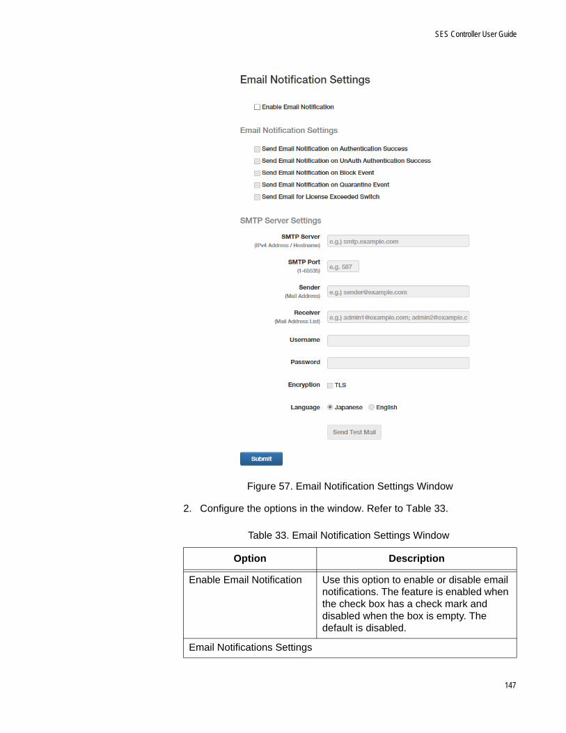
SES Controller User Guide
Figure 57. Email Notification Settings Window
2. Configure the options in the window. Refer to Table 33.
Table 33. Email Notification Settings Window
Option Description
Enable Email Notification Use this option to enable or disable email notifications. The feature is enabled when the check box has a check mark and disabled when the box is empty. The default is disabled.
Email Notifications Settings
147

Chapter 7: System Settings
Send Email Notification on Authentication Success
Enable this option to have the SES controller send emails when hosts with location or schedule policies successfully connect to OpenFlow ports.
Send Email Notification on UnAuth Authentication Success
Enable this option to have the SES controller send emails when hosts successfully use the secondary policies in unauthorized groups to connect to switch ports. For background information, refer to “Introduction to Unauthorized Groups” on page 130.
Send Email Notification on Block Event
Enable this option to have the SES controller send emails when hosts are blocked.
Send Email Notification on Quarantine Event
Enable this option to have the SES controller send emails when hosts are assigned to the quarantine VID.
Send Email Notification on License Exceeded Switch
Enable this option to have the SES controller send emails when the number of an OpenFlow switches exceed the available licenses. For more information, refer to “Managing the SES Controller Licenses and Software” on page 167.
SMTP Server Settings
SMTP Server Enter the IPv4 address or hostname of the email server. You can enter only one address.
SMTP Port Enter the protocol port number of the server. The range is 0 to 65535.
Sender Enter the email address of the SES controller’s account on the SMTP server. You can enter only one sender address.
Receiver Enter the email address of the person to receive notifications. You can enter more than one receiver. Separate multiple addresses with semicolons (;).
Username Enter the username of the SES controller’s account on the SMTP server.
Table 33. Email Notification Settings Window (Continued)
Option Description
148

SES Controller User Guide
3. Click the Submit button to implement your changes.
4. To send a test email, click the Send Test Email button.
Password Enter the password of the SES controller’s account on the SMTP server.
Encryption Add a check mark to the check box if the SMTP server uses TLS encryption. Otherwise, leave the box empty.
Language Click either Japanese or English to indicate the language for the emails.
Table 33. Email Notification Settings Window (Continued)
Option Description
149

Chapter 7: System Settings
Configuring the Web Server
This sections contains the following procedures:
“Changing the HTTP or HTTPS Web Mode” on page 150
“Adding an SSL Certificate” on page 151
“Restoring the Allied Telesis SSL Certificate” on page 152
Changing theHTTP or HTTPS
Web Mode
You can use HTTP or HTTPS to manage the SES controller with a web browser. The HTTP mode is non-secure. Management sessions conducted in this mode are vulnerable to eavesdropping because your management workstation and the controller transmit packets in clear text. In contrast, the secure HTTPS mode protects management sessions by encrypting packets. Only the controller and your management workstation can decrypt the packets.
Caution
Management sessions conducted in the HTTP mode are non-secure. The packets exchanged by your web browser application and the SES controller are sent in clear text, leaving them vulnerable to snooping.
Here are the guidelines to configuring the web server:
The default is the HTTPS mode.
The web server cannot operate in both HTTP and HTTPS modes at the same time.
The switch supports HTTP v1.0 and v1.1 protocols.
Your management workstations must have Layer 3 connectivity to the IPv4 address of the SES controller.
HTTPS mode requires that the web server have a certificate with an encryption key to encrypt and decrypt packets. Also included in the certificate is a distinguished name identifying the owner of the certificate. The SES controller comes with a default certificate. For instructions on how to change the certificate, refer to “Adding an SSL Certificate” on page 151.
NoteChanging the HTTP or HTTPS mode of the SES controller will interrupt your management session. To resume managing the controller, start a new session using the new web server mode.
150
SES Controller User Guide
To change the HTTP or HTTPS mode on the web server, perform the following procedure:
1. Select System Settings -> Network Settings.
The SES controller displays the Network Settings window. Refer to Figure 55 on page 143. The Interfaces section of the window is explained in “Changing the IPv4 Address of the SES Controller” on page 143.
2. In the Services section, click either HTTP or HTTPS. The default is HTTPS. You cannot activate both modes.
3. For Web Server Port Number, enter the protocol port number for the web server mode. The default values are 80 for HTTP and 443 for HTTPS.
4. Click the Submit button to add your change to the SES controller.
NoteThe SES controller stops responding to your web browser. To resume managing the controller, start a new management session using the new web server mode.
Adding an SSLCertificate
The SES controller comes with an SSL certificate for HTTPS web management. This section explains how to replace the certificate with one of your own. The SSL certificate specifications are listed in Table 34.
NoteIf the HTTPS server certificate has an intermediate CA or crossroot certificate, you must concatenate the files into one server file. For instructions, contact the issue of the certificate.
NoteReplacing the server certificate will interrupt your management session. You will have to start a new management session at the completion of the procedure.
Table 34. SSL Certificate Specification
Requirement Specification
Format X.509, RFC 6818
Encryption PEM (Privacy Enhanced Mail) format
Extension .crt
151

Chapter 7: System Settings
To add your own SSL certificate to the SES controller, perform the following procedure:
1. Select System Settings -> System Information.
2. In the SSL Certificate section of the window, click the Upload SSL Certificate button.
The SES controller displays the SSL Certificate Settings window. Refer to Figure 58.
Figure 58. SSL Certificate Settings
3. Click the Please select an SSL Private Key Browse button and locate the private key file on your computer or network server.
4. Click the Please select an SSL Certificate Key Browse button and locate the SSL certificate file on your computer or network server.
5. Click the Upload button to upload the files to the SES controller.
The controller replaces its current certificate files with the uploaded files.
NoteThe SES controller stops responding to your web browser. To resume managing the controller, start a new management session.
Restoring theAllied Telesis SSL
Certificate
To restore the original Allied Telesis SSL certificate on the web server for HTTPS web management, perform the following procedure:
1. Select System Settings -> System Information.
2. Scroll down to the SSL Certificate section in the window
3. In the SSL Certificate section, click the Reset SSL Files Reset button.
The SES controller restores its default SSL certificate files.
152

SES Controller User Guide
NoteYour management session is interrupted if you are using HTTPS. To resume the session, start a new management session.
153

Chapter 7: System Settings
Setting the Date and Time
The procedures in this section are listed here:
“Manually Setting the Date and Time” next
“Setting the Date and Time from an NTP Server” on page 155
Manually Settingthe Date and
Time
To manually set the date and time on the SES controller, perform the following procedure:
1. Select System Settings -> Date Times Settings.
The SES controller displays the System Time Settings Window. Refer to Figure 59.
Figure 59. System Time Settings Window
2. From the Timezone pull-down menu, select the timezone of the SES controller’s location.
3. For the Daylight Savings Time setting, do one of the following:
The Enable Daylight Savings Time check box needs to have a check mark if the location of the SES controller observes Daylight Savings Time. If the box does not have a check mark, click the box to add it. When the option is enabled, the controller automatically
154

SES Controller User Guide
adjusts its time at the start and end of Daylight Savings Time.
The Enable Daylight Savings Time check box needs to be empty if the location of the SES controller does not observe Daylight Savings Time. If the box has a check mark, click the box to remove it.
4. Click the Timezone Submit button to add your change to the controller.
5. In the System Time fields, enter the date and time. Here are the guidelines:
The year must be four digits (YYYY).
The month and day must be two digits each (MM / DD).
The hours, minutes, and seconds must be two digits each (HH : MM : SS).
Use the 24-four format to specify the time. For example, 8:30pm is entered as 20:30:00.
6. Click the Submit button in the System Time section.
7. Verify that the NTP Server Address field at the bottom of the window is empty. If the field has an IP address or hostname, delete it and then click the Submit button in the NTP section.
Setting the Dateand Time from an
NTP Server
This section contains the procedure for setting the date and time on the SES controller from an Network Time Protocol (NTP) server. The procedure requires the following information:
The IP address or hostname of a NTP server on your network or the Internet.
The timezone of the SES controller. The controller uses the timezone to determine the number of hours and minutes it is ahead or behind Coordinated Universal Time (UTC). This is referred to as the UTC offset.
Whether the timezone of the SES controller is in Daylight Savings Time.
NoteIf the NTP server will be designated by a hostname instead of an IPv4 address, be sure to configure the DNS settings of the IP interfaces. For instructions, refer to “Changing the IPv4 Address of the SES Controller” on page 143.
To configure the SES controller to receive the date and time from an NTP server, perform the following procedure:
155
Chapter 7: System Settings
1. Select System Settings -> Date Times Settings.
The SES controller displays the System Time Settings Window. Refer to Figure 59 on page 154.
2. With the Timezone pull-down menu, select the timezone of the location of the SES controller server.
3. For the Daylight Savings Time setting, do one of the following:
The Enable Daylight Savings Time check box needs to have a check mark if the location of the SES controller observes Daylight Savings Time. If the box does not have a check mark, click the box to add it. When the option is enabled, the controller automatically adjusts its time at the start and end of Daylight Savings Time.
The Enable Daylight Savings Time check box needs to be empty if the location of the SES controller does not observe Daylight Savings Time. If the box has a check mark, click the box to remove it.
4. Click the Timezone Submit button to add your change to the SES controller.
5. Click the NTP Server Address field and enter the IP address or hostname of an NTP server.
6. Click the NTP Submit button.
The SES controller queries your network or the Internet for the specified NTP server. The controller’s server sets its date and time according to the information from the NTP server.
156

SES Controller User Guide
Backing Up or Restoring System Information
This section contains procedures for backing up, restoring, or erasing the SES controller system information in Table 35.
NoteFor instructions on how to backup or restore configuration information on switches, hosts, policies, and unauthorized groups, refer to “Backing Up or Restoring Authentication Information” on page 161.
You cannot archive the SES controller information in Table 36:
Table 35. Archived SES Controller System Configuration
Setting Configuration Window
Username and password Administrator Settings window in Figure 54 on page 142
HTTP or HTTPS setting and web server port number
Network Settings window in Figure 55 on page 143
Logging output and syslog host settings
Log Settings window in Figure 62 on page 165
Date and time settings and SNTP server
System Time Settings window in Figure 59 on page 154
OpenFlow settings OpenFlow Settings window in Figure 66 on page 170
Trap monitoring settings Trap Monitoring Settings window in Figure 70 on page 178
Email notification settings Email Notification Settings window in Figure 57 on page 147
Table 36. Non-archived SES Controller Settings
Setting Window
IP addresses of the SES controller interfaces
Network Settings window in Figure 55 on page 143
Trap monitor rule file Maintenance window in Figure 69 on page 176
157
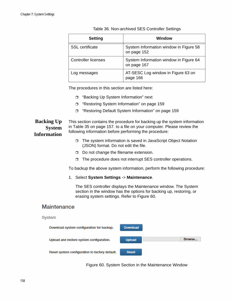
Chapter 7: System Settings
The procedures in this section are listed here:
“Backing Up System Information” next
“Restoring System Information” on page 159
“Restoring Default System Information” on page 159
Backing UpSystem
Information
This section contains the procedure for backing up the system information in Table 35 on page 157. to a file on your computer. Please review the following information before performing the procedure:
The system information is saved in JavaScript Object Notation (JSON) format. Do not edit the file.
Do not change the filename extension.
The procedure does not interrupt SES controller operations.
To backup the above system information, perform the following procedure:
1. Select System Settings -> Maintenance.
The SES controller displays the Maintenance window. The System section in the window has the options for backing up, restoring, or erasing system settings. Refer to Figure 60.
Figure 60. System Section in the Maintenance Window
SSL certificate System Information window in Figure 58 on page 152
Controller licenses System Information window in Figure 64 on page 167
Log messages AT-SESC Log window in Figure 63 on page 166
Table 36. Non-archived SES Controller Settings
Setting Window
158
SES Controller User Guide
2. Click the Download system configuration for backup Download button.
3. Follow the prompts to store the file with the SES controller settings on your computer.
Restoring SystemInformation
This section contains the procedure for restoring system information from a backup file previously stored on your computer to the SES controller. For a list of system information, refer to Table 35 on page 157. Please review the following information before performing the procedure:
The SES controller immediately implements the system settings in the backup file after uploading the file.
You do not have to reset the controller after restoring system information. However, there may be a momentary disruption to controller operations as it implements the system settings from the backup file.
Performing this procedure may interrupt your web browser management session. It might be necessary to start a new session at the completion of the procedure.
To restore system information from a JSON backup file, perform the following procedure:
1. Select System Settings -> Maintenance.
The SES controller displays the Maintenance window. The System section in the window has the options for backing up, restoring, or erasing system settings. Refer to Figure 60 on page 158.
2. Click the Browse button and locate the system information file you want to restore to the SES controller.
3. Click the Upload and restore system configuration Upload button.
The SES controller downloads the file and implements the restored system settings.
NoteIf the SES controller stops responding to your web browser, start a new management session. If the system backup file had different settings for HTTP or HTTPS mode, or the manager password, be sure to use the settings in the restored file when starting the new web management session.
Restoring DefaultSystem
Information
This section contains the procedure for restoring the default settings to the SES controller’s system information, listed in Table 35 on page 157. Please read the following information before performing the procedure:
You do not have to restart the SES controller after restoring the
159

Chapter 7: System Settings
default settings to the system information. However, there may be a momentary disruption to SES controller operations as it activates the settings.
Performing this procedure may interrupt your web browser management session. You might need to start a new session at the completion of the procedure.
To restore the default settings to the SES controller’s system information, perform the following information:
1. Select System Settings -> Maintenance.
The System section in the Maintenance window has selections for backing up, restoring, or erasing the system settings. Refer to Figure 60 on page 158.
2. Click the Reset system configuration to factory default Reset button.
The SES controller displays a confirmation prompt.
3. Click the Continue button to reset the system information or the Cancel button to cancel the procedure.
The SES controller restores the default settings to its system information. If it stops responding to your web browser, start a new management session using the HTTPS mode and the username and password “manager” and “friend”, respectively. Since restoring the default settings does not change the SES controller’s IP address, use the same IP address as before the procedure.
160

SES Controller User Guide
Backing Up or Restoring Authentication Information
The procedures in this section describe how to backup, restore, or erase the following authentication data in the SES controller:
OpenFlow switch information
Host MAC address information
Network, location, and schedule policies
Policy devices
Unauthorized groups
NoteFor instructions on how to backup system information, such as web server and syslog host settings, refer to “Backing Up or Restoring System Information” on page 157.
The procedures are listed here:
“Backing Up Authentication Information” next
“Restoring Authentication Information” on page 162
“Erasing All Authentication Information” on page 163
Backing UpAuthentication
Information
This section contains the procedure for backing up the above authentication information to a file on your computer. Please review the following information before performing the procedure:
This procedure does not interrupt SES controller operations.
The information is saved in a Comma Separated Text (CSV) file. Do not edit the contents.
Do not change the filename extension.
To backup the authentication information, perform the following procedure:
1. Select System Settings -> Maintenance.
The SES controller displays the Maintenance window. The options for backing up, restoring, or erasing hosts, policies, and policy devices are in the Authentication Data section of the window. Refer to Figure 61 on page 162.
161

Chapter 7: System Settings
Figure 61. Authentication Data Section in the Maintenance Window
2. Click the Download authentication data for backup Download button.
3. Follow the prompts to store the file on your computer or a network server.
RestoringAuthentication
Information
This section contains the procedure for restoring authentication information to the SES controller from a backup file. Please review the following information before performing this procedure:
The authentication information is listed in “Backing Up or Restoring Authentication Information” on page 161.
Restoring authentication information does not affect the current registered hosts or their policies in the SES controller’s database. They remain unchanged. To replace all current registered hosts and policies with the information from the backup file, perform “Erasing All Authentication Information” on page 163 first before performing this procedure.
After uploading the file, the SES controller compares the flow instructions in the file against the instructions in its database. Where there are differences, the controller issues new flow instructions to the appropriate switches. Depending on the number of instructions and changes, it can take from a few seconds to several minutes to update all switches.
To restore the configuration information about switches, hosts, policies, and policy devices to the SES controller from a backup file, perform the following procedure:
1. Select System Settings -> Maintenance.
The options for backing up, restoring, or erasing the authentication information are in the Authentication Data section in the Maintenance window. Refer to Figure 61 on page 162.
162

SES Controller User Guide
2. Click the Browse button in Upload and restore authentication data, and locate the authentication data file you want to restore to the SES controller.
3. Click the Upload and restore authentication data Upload button.
The controller SES uploads the file and updates the flow instructions on the switches.
Erasing AllAuthentication
Information
This section contains the procedure for erasing the configuration information for all switches, hosts, policies, and policy devices from the SES controller.
Caution
This procedure is disruptive to network operations. The switches block all ports under OpenFlow control and stop forwarding host traffic.
Please review the following information before performing this procedure:
The SES controller immediately begins to relearn OpenFlow switches and host MAC addresses.
The switches and host MAC addresses are initially learned as unregistered. You have to register them before they can forward traffic. For instructions, refer to “Registering Switches” on page 46 and “Registering Hosts” on page 63.
To delete all authentication data from the SES controller, perform the following procedure:
1. Select System Settings -> Maintenance.
The options for backing up, restoring, or erasing the authentication information are in the Authentication Data section in the Maintenance window. Refer to Figure 61 on page 162.
2. Click the Erase all authentication data in this system Reset button.
The SES controller displays a confirmation prompt.
3. Click the OK button to delete all authentication information or the Cancel button to cancel the procedure.
163
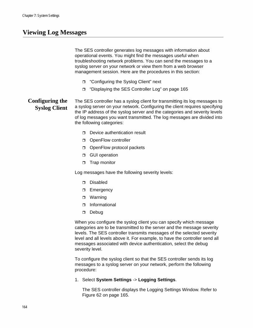
Chapter 7: System Settings
Viewing Log Messages
The SES controller generates log messages with information about operational events. You might find the messages useful when troubleshooting network problems. You can send the messages to a syslog server on your network or view them from a web browser management session. Here are the procedures in this section:
“Configuring the Syslog Client” next
“Displaying the SES Controller Log” on page 165
Configuring theSyslog Client
The SES controller has a syslog client for transmitting its log messages to a syslog server on your network. Configuring the client requires specifying the IP address of the syslog server and the categories and severity levels of log messages you want transmitted. The log messages are divided into the following categories:
Device authentication result
OpenFlow controller
OpenFlow protocol packets
GUI operation
Trap monitor
Log messages have the following severity levels:
Disabled
Emergency
Warning
Informational
Debug
When you configure the syslog client you can specify which message categories are to be transmitted to the server and the message severity levels. The SES controller transmits messages of the selected severity level and all levels above it. For example, to have the controller send all messages associated with device authentication, select the debug severity level.
To configure the syslog client so that the SES controller sends its log messages to a syslog server on your network, perform the following procedure:
1. Select System Settings -> Logging Settings.
The SES controller displays the Logging Settings Window. Refer to Figure 62 on page 165.
164
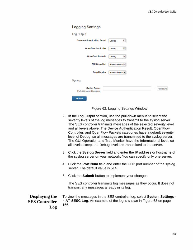
SES Controller User Guide
Figure 62. Logging Settings Window
2. In the Log Output section, use the pull-down menus to select the severity levels of the log messages to transmit to the syslog server. The SES controller transmits messages of the selected severity level and all levels above. The Device Authentication Result, OpenFlow Controller, and OpenFlow Packets categories have a default severity level of Debug, so all messages are transmitted to the syslog server. The GUI Operation and Trap Monitor have the Informational level, so all levels except the Debug level are transmitted to the server.
3. Click the Syslog Server field and enter the IP address or hostname of the syslog server on your network. You can specify only one server.
4. Click the Port Num field and enter the UDP port number of the syslog server. The default value is 514.
5. Click the Submit button to implement your changes.
The SES controller transmits log messages as they occur. It does not transmit any messages already in its log.
Displaying theSES Controller
Log
To view the messages in the SES controller log, select System Settings -> AT-SESC Log. An example of the log is shown in Figure 63 on page 166.
165

Chapter 7: System Settings
Figure 63. SESC Log Window
The options in the window are described in Table 37.
Table 37. Options in the SESC Window
Option Description
Clear All Logs Use this button to clear all messages from the logs.
Download Use this button to download the log as a file to your computer. The maximum is 300,000 messages. The default filename extension is LOG and default file format is text. To download the messages, click the button and follow the prompts.
Update Use this button to refresh the window.
166

SES Controller User Guide
Managing the SES Controller Licenses and Software
This section contains the following procedures:
“Installing or Deleting SES Controller Licenses” next
“Displaying the SES Controller Software Version Number” on page 168
“Installing New SES Controller Software” on page 168
Installing orDeleting SES
ControllerLicenses
The SES controller uses the following licenses:
AT-FL-SESC-Base-5YR - This is the base license. It supports up to ten switches for five years. The controller must have a base license. You have to install it during the initial installation. The controller can have only one base license.
AT-FL-SESC-ADD50-5YR - This license adds support for an additional fifty switches for five years. You can install any number of this license type on the controller.
Adding a new license to the SES controller requires the following information from the license certificate:
Serial number
Authentication key
To add SES controller licenses, perform the following procedure:
1. Select System Settings -> System Information.
Licenses are managed in the Licenses section of the System Information window. Refer to Figure 64.
Figure 64. Licenses Section in the System Information Window
167
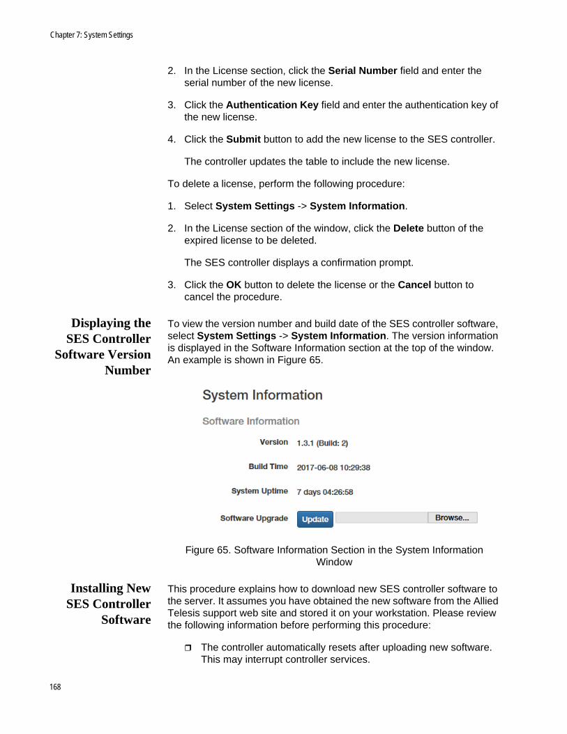
Chapter 7: System Settings
2. In the License section, click the Serial Number field and enter the serial number of the new license.
3. Click the Authentication Key field and enter the authentication key of the new license.
4. Click the Submit button to add the new license to the SES controller.
The controller updates the table to include the new license.
To delete a license, perform the following procedure:
1. Select System Settings -> System Information.
2. In the License section of the window, click the Delete button of the expired license to be deleted.
The SES controller displays a confirmation prompt.
3. Click the OK button to delete the license or the Cancel button to cancel the procedure.
Displaying theSES Controller
Software VersionNumber
To view the version number and build date of the SES controller software, select System Settings -> System Information. The version information is displayed in the Software Information section at the top of the window. An example is shown in Figure 65.
Figure 65. Software Information Section in the System Information Window
Installing NewSES Controller
Software
This procedure explains how to download new SES controller software to the server. It assumes you have obtained the new software from the Allied Telesis support web site and stored it on your workstation. Please review the following information before performing this procedure:
The controller automatically resets after uploading new software. This may interrupt controller services.
168

SES Controller User Guide
This procedure interrupts your management session. To resume managing the controller, start a new session at the completion of the procedure.
Installing new software does not delete the existing licenses.
NoteInstalling new software does not affect the system or authentication configuration information. However, Allied Telesis recommends backing up the configuration information before performing the procedure. For instructions, refer to “Backing Up System Information” on page 158 and “Backing Up Authentication Information” on page 161.
To install new SES controller software, perform the following procedure:
1. Select System Settings -> System Information.
2. In the Software Information section of the window, click the Software Update Browse button and locate the file with the new SES controller software on your workstation. Refer to Figure 65 on page 168.
3. Click the Software Upgrade Update button.
The SES controller uploads the firmware file and the server writes it to its storage disk. Afterwards, the controller automatically reboots with the new software.
4. To resume managing the controller, wait two minutes and then start a new management session.
169

Chapter 7: System Settings
Configuring the OpenFlow SES Controller Settings
To configure the OpenFlow SES controller settings, perform the following procedure:
1. Select System Settings - > OpenFlow Settings.
The OpenFlow Settings window is shown in Figure 38.
Figure 66. OpenFlow Settings Window
2. Configure the options. Refer to Table 38 on page 171.
170
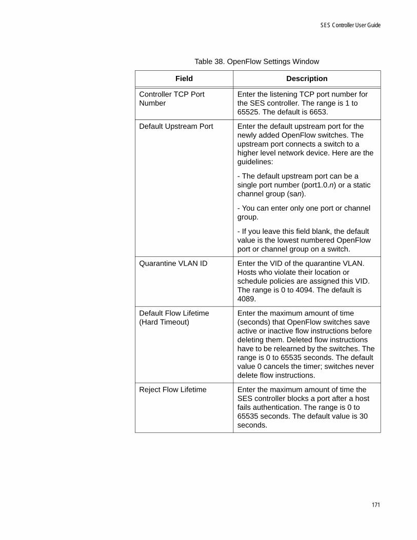
SES Controller User Guide
Table 38. OpenFlow Settings Window
Field Description
Controller TCP Port Number
Enter the listening TCP port number for the SES controller. The range is 1 to 65525. The default is 6653.
Default Upstream Port Enter the default upstream port for the newly added OpenFlow switches. The upstream port connects a switch to a higher level network device. Here are the guidelines:
- The default upstream port can be a single port number (port1.0.n) or a static channel group (san).
- You can enter only one port or channel group.
- If you leave this field blank, the default value is the lowest numbered OpenFlow port or channel group on a switch.
Quarantine VLAN ID Enter the VID of the quarantine VLAN. Hosts who violate their location or schedule policies are assigned this VID. The range is 0 to 4094. The default is 4089.
Default Flow Lifetime (Hard Timeout)
Enter the maximum amount of time (seconds) that OpenFlow switches save active or inactive flow instructions before deleting them. Deleted flow instructions have to be relearned by the switches. The range is 0 to 65535 seconds. The default value 0 cancels the timer; switches never delete flow instructions.
Reject Flow Lifetime Enter the maximum amount of time the SES controller blocks a port after a host fails authentication. The range is 0 to 65535 seconds. The default value is 30 seconds.
171
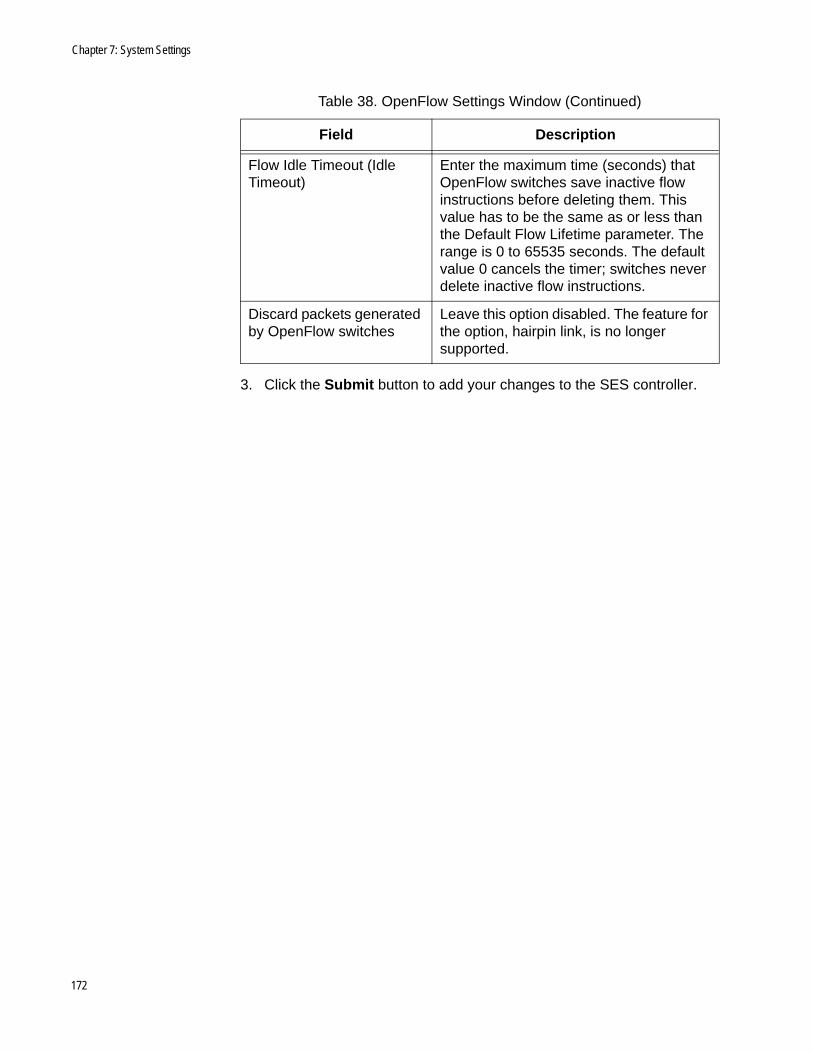
Chapter 7: System Settings
3. Click the Submit button to add your changes to the SES controller.
Flow Idle Timeout (Idle Timeout)
Enter the maximum time (seconds) that OpenFlow switches save inactive flow instructions before deleting them. This value has to be the same as or less than the Default Flow Lifetime parameter. The range is 0 to 65535 seconds. The default value 0 cancels the timer; switches never delete inactive flow instructions.
Discard packets generated by OpenFlow switches
Leave this option disabled. The feature for the option, hairpin link, is no longer supported.
Table 38. OpenFlow Settings Window (Continued)
Field Description
172
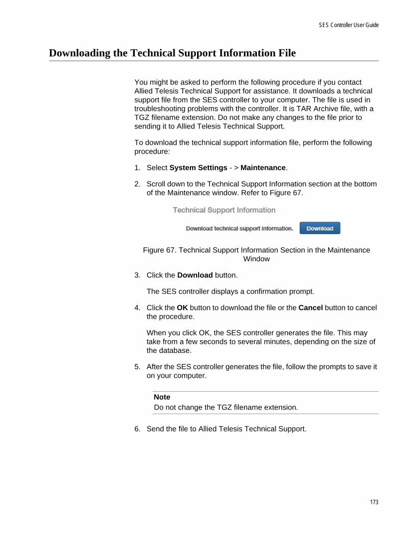
SES Controller User Guide
Downloading the Technical Support Information File
You might be asked to perform the following procedure if you contact Allied Telesis Technical Support for assistance. It downloads a technical support file from the SES controller to your computer. The file is used in troubleshooting problems with the controller. It is TAR Archive file, with a TGZ filename extension. Do not make any changes to the file prior to sending it to Allied Telesis Technical Support.
To download the technical support information file, perform the following procedure:
1. Select System Settings - > Maintenance.
2. Scroll down to the Technical Support Information section at the bottom of the Maintenance window. Refer to Figure 67.
Figure 67. Technical Support Information Section in the Maintenance Window
3. Click the Download button.
The SES controller displays a confirmation prompt.
4. Click the OK button to download the file or the Cancel button to cancel the procedure.
When you click OK, the SES controller generates the file. This may take from a few seconds to several minutes, depending on the size of the database.
5. After the SES controller generates the file, follow the prompts to save it on your computer.
NoteDo not change the TGZ filename extension.
6. Send the file to Allied Telesis Technical Support.
173
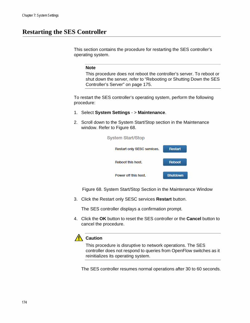
Chapter 7: System Settings
Restarting the SES Controller
This section contains the procedure for restarting the SES controller’s operating system.
NoteThis procedure does not reboot the controller’s server. To reboot or shut down the server, refer to “Rebooting or Shutting Down the SES Controller’s Server” on page 175.
To restart the SES controller’s operating system, perform the following procedure:
1. Select System Settings - > Maintenance.
2. Scroll down to the System Start/Stop section in the Maintenance window. Refer to Figure 68.
Figure 68. System Start/Stop Section in the Maintenance Window
3. Click the Restart only SESC services Restart button.
The SES controller displays a confirmation prompt.
4. Click the OK button to reset the SES controller or the Cancel button to cancel the procedure.
Caution
This procedure is disruptive to network operations. The SES controller does not respond to queries from OpenFlow switches as it reinitializes its operating system.
The SES controller resumes normal operations after 30 to 60 seconds.
174

SES Controller User Guide
Rebooting or Shutting Down the SES Controller’s Server
To reboot of shutdown the SES controller’s server, perform the following procedure.
1. Select System Settings - > Maintenance.
2. Scroll down to the System Start/Stop section in the Maintenance window. Refer to Figure 68 on page 174.
3. Click the Reboot this host Reboot button or the Power off this host Shutdown button.
The SES controller displays a confirmation prompt.
4. Click the OK button to reboot or shutdown the controller’s server or the Cancel button to cancel the procedure.
Caution
Rebooting or shutting down the SES controller’s server is disruptive to network operations. When rebooted, the controller requires approximately two minutes to initialize its operating system.
175

Chapter 7: System Settings
Uploading the Trap Monitoring Rule File
This procedure explains how to upload the trap monitoring rule file from Allied Telesis to the SES controller, for the enhanced firewall protection feature. The controller uses the file to monitor the syslog messages from firewalls for warnings of possible threats on their WAN ports. The following procedure assumes you have already obtained the file from Allied Telesis and stored it on your computer. For instructions on obtaining the file, contact an Allied Telesis sales representative.
To upload the rule file to the SES controller, perform the following procedure:
1. Select System Settings - > Maintenance.
2. Scroll down to the Trap Monitor section in the Maintenance window. Refer to Figure 69.
Figure 69. Trap Monitor Section in the Maintenance Window
3. Click the Browse button and locate the rule file on your computer.
4. Click the Upload button.
The SES controller uploads the file to the server.
5. If you have not already configured the SES controller’s trap monitoring settings, go to “Configuring the Enhanced Firewall Protection Feature” on page 177
176
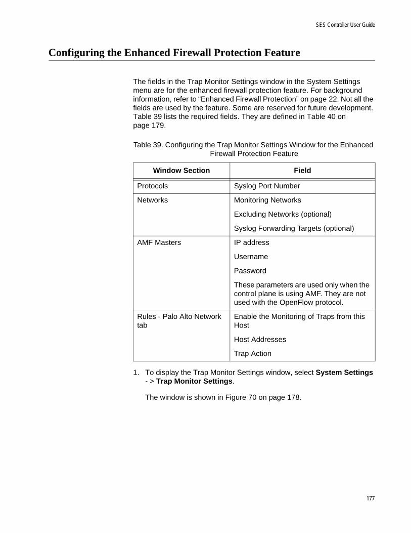
SES Controller User Guide
Configuring the Enhanced Firewall Protection Feature
The fields in the Trap Monitor Settings window in the System Settings menu are for the enhanced firewall protection feature. For background information, refer to “Enhanced Firewall Protection” on page 22. Not all the fields are used by the feature. Some are reserved for future development. Table 39 lists the required fields. They are defined in Table 40 on page 179.
1. To display the Trap Monitor Settings window, select System Settings - > Trap Monitor Settings.
The window is shown in Figure 70 on page 178.
Table 39. Configuring the Trap Monitor Settings Window for the Enhanced Firewall Protection Feature
Window Section Field
Protocols Syslog Port Number
Networks Monitoring Networks
Excluding Networks (optional)
Syslog Forwarding Targets (optional)
AMF Masters IP address
Username
Password
These parameters are used only when the control plane is using AMF. They are not used with the OpenFlow protocol.
Rules - Palo Alto Network tab
Enable the Monitoring of Traps from this Host
Host Addresses
Trap Action
177

Chapter 7: System Settings
Figure 70. Trap Monitor Settings Window
NoteIf the Rules section at the bottom of the window does not include a Palo Alto network tabs, you need to upload the trap monitoring rule file to the SES controller. For instructions, refer to “Uploading the Trap Monitoring Rule File” on page 176.
178
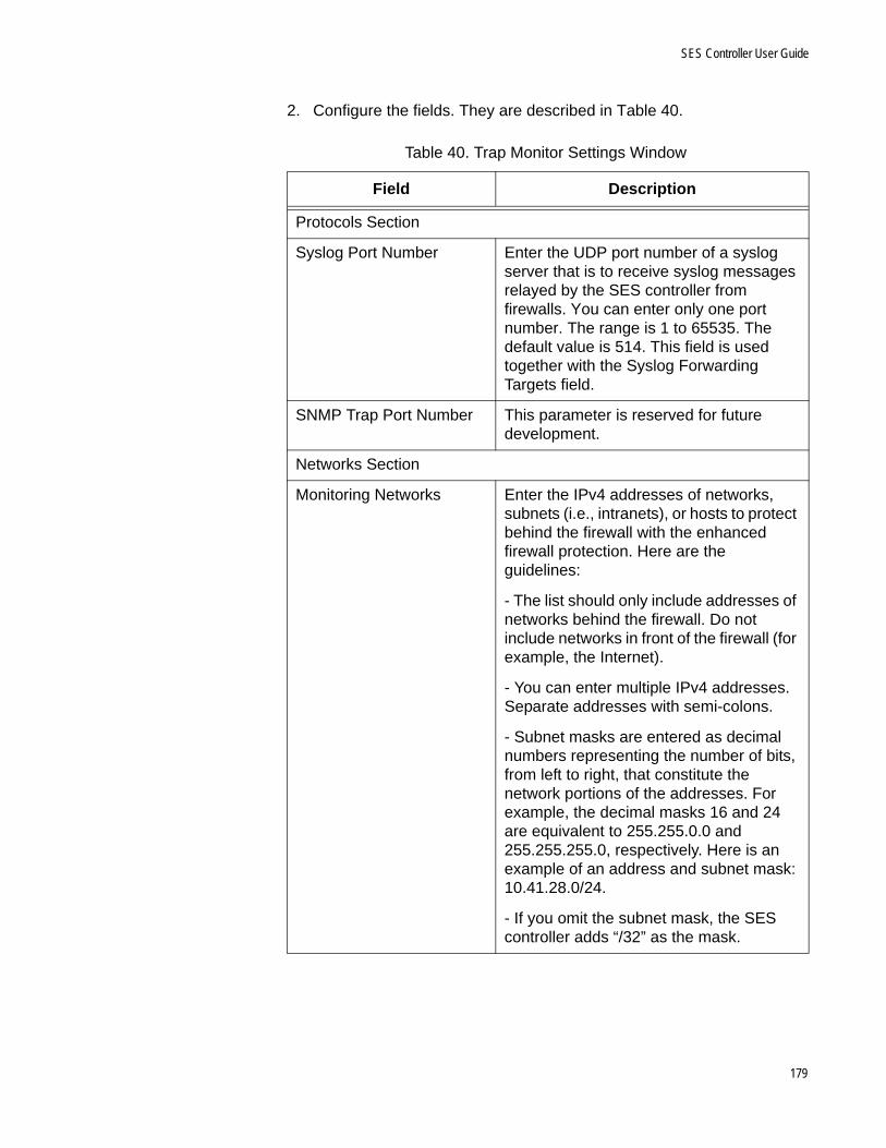
SES Controller User Guide
2. Configure the fields. They are described in Table 40.
Table 40. Trap Monitor Settings Window
Field Description
Protocols Section
Syslog Port Number Enter the UDP port number of a syslog server that is to receive syslog messages relayed by the SES controller from firewalls. You can enter only one port number. The range is 1 to 65535. The default value is 514. This field is used together with the Syslog Forwarding Targets field.
SNMP Trap Port Number This parameter is reserved for future development.
Networks Section
Monitoring Networks Enter the IPv4 addresses of networks, subnets (i.e., intranets), or hosts to protect behind the firewall with the enhanced firewall protection. Here are the guidelines:
- The list should only include addresses of networks behind the firewall. Do not include networks in front of the firewall (for example, the Internet).
- You can enter multiple IPv4 addresses. Separate addresses with semi-colons.
- Subnet masks are entered as decimal numbers representing the number of bits, from left to right, that constitute the network portions of the addresses. For example, the decimal masks 16 and 24 are equivalent to 255.255.0.0 and 255.255.255.0, respectively. Here is an example of an address and subnet mask: 10.41.28.0/24.
- If you omit the subnet mask, the SES controller adds “/32” as the mask.
179
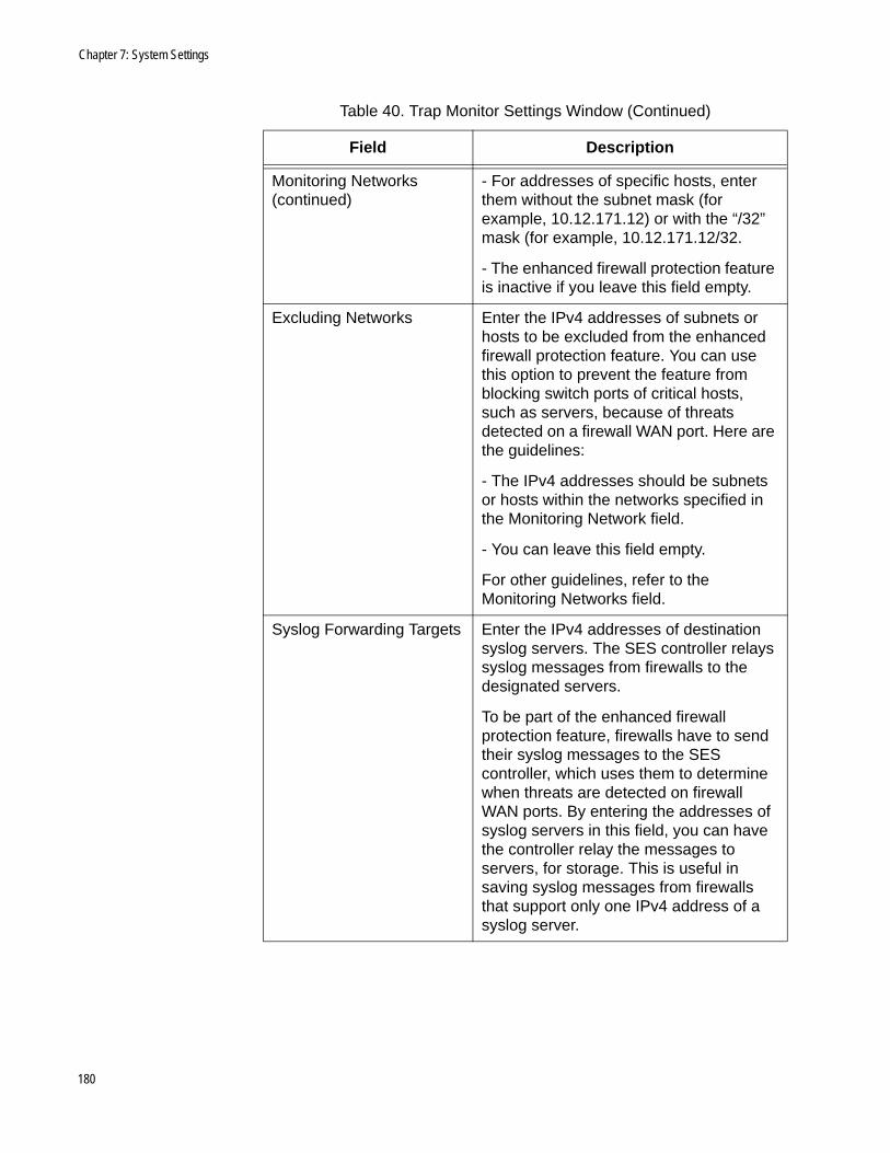
Chapter 7: System Settings
Monitoring Networks(continued)
- For addresses of specific hosts, enter them without the subnet mask (for example, 10.12.171.12) or with the “/32” mask (for example, 10.12.171.12/32.
- The enhanced firewall protection feature is inactive if you leave this field empty.
Excluding Networks Enter the IPv4 addresses of subnets or hosts to be excluded from the enhanced firewall protection feature. You can use this option to prevent the feature from blocking switch ports of critical hosts, such as servers, because of threats detected on a firewall WAN port. Here are the guidelines:
- The IPv4 addresses should be subnets or hosts within the networks specified in the Monitoring Network field.
- You can leave this field empty.
For other guidelines, refer to the Monitoring Networks field.
Syslog Forwarding Targets Enter the IPv4 addresses of destination syslog servers. The SES controller relays syslog messages from firewalls to the designated servers.
To be part of the enhanced firewall protection feature, firewalls have to send their syslog messages to the SES controller, which uses them to determine when threats are detected on firewall WAN ports. By entering the addresses of syslog servers in this field, you can have the controller relay the messages to servers, for storage. This is useful in saving syslog messages from firewalls that support only one IPv4 address of a syslog server.
Table 40. Trap Monitor Settings Window (Continued)
Field Description
180

SES Controller User Guide
Syslog Forwarding Targets(continued)
Here are the guidelines:
- You can specify multiple destination syslog servers. Separate the server IPv4 addresses with semicolons. Here is an example:
10.122.67.2;10;122.101.90
- You can include a secondary syslog port number with an IPv4 address if a destination syslog server uses a different port number than the value in the Syslog Port Number field in this window. Separate the IPv4 address from the port number with a colon. Here is an example:
10.122.67.2:9000
- The SES controller changes the sender’s IPv4 address in syslog messages to its own address. However, the information inside the syslog messages themselves are not changed.
SNMP Trap Forwarding Targets
This parameter is reserved for future development.
AMF Masters Enter the IPv4 address of the AMF master. You can specify only one IP address.
Enter a value for this field and the username and password fields only if you are using AMF for the control plane. Leave the fields empty if you are using the OpenFlow protocol.
Username Enter the username of the privileged user on the AMF master. It is case-sensitive.
Password Enter the password of the privileged user on the AMF master. It is case-sensitive.
Rules Section - Palo Alto Networks Tab
Enable the monitoring of traps from this host.
Enable or disable the enhanced firewall protection feature. The feature is enabled when the check box has a check mark. The default value is disabled.
Table 40. Trap Monitor Settings Window (Continued)
Field Description
181
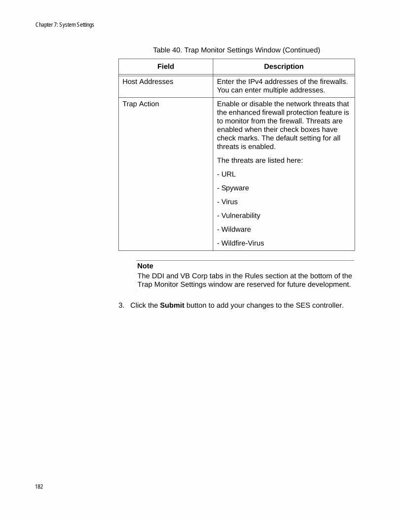
Chapter 7: System Settings
NoteThe DDI and VB Corp tabs in the Rules section at the bottom of the Trap Monitor Settings window are reserved for future development.
3. Click the Submit button to add your changes to the SES controller.
Host Addresses Enter the IPv4 addresses of the firewalls. You can enter multiple addresses.
Trap Action Enable or disable the network threats that the enhanced firewall protection feature is to monitor from the firewall. Threats are enabled when their check boxes have check marks. The default setting for all threats is enabled.
The threats are listed here:
- URL
- Spyware
- Virus
- Vulnerability
- Wildware
- Wildfire-Virus
Table 40. Trap Monitor Settings Window (Continued)
Field Description
182

Appendix A
Configuring Your Web Browser
This chapter contains instructions on how to configure your web browser for the SES controller. The chapter includes the following sections:
“Enabling JavaScript on Your Web Browser” on page 184
“Making the SES Controller a Trusted Website” on page 186
183

Chapter : Configuring Your Web Browser
Enabling JavaScript on Your Web Browser
Your web browser has to have JavaScript to support the browser windows in the SES controller. The following procedure explains how to enable JavaScript in Microsoft Windows Internet Explorer. If you are using a different web browser, refer to the appropriate documentation for instructions.
To enable JavaScript in Microsoft Windows Internet Explorer, do the following:
1. Open the Windows Internet Explorer.
2. Click Tools from the menu bar.
3. Select Internet options from the drop-down menu.
The Internet Options window is displayed.
4. Click the Security tab on the Internet Options window.
The Internet Options window is shown in Figure 71.
Figure 71. Security Tab in the Internet Options Window
5. Click the Custom Level... button.
184

SES Controller User Guide
The Security Settings Internet Zone window is shown in Figure 72.
Figure 72. Security Settings Window
6. Scroll down to the Scripting section and Active scripting subsection.
7. Change the setting of Active scripting to Enable.
8. Click OK.
9. Restart the Internet Explorer.
JavaScript is now enabled on your web browser. For instructions on how to start a management session, refer to “Starting a Management Session” on page 29.
185
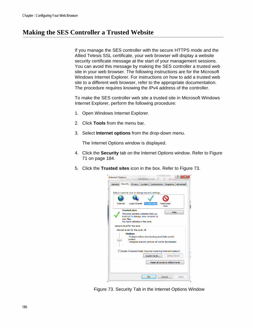
Chapter : Configuring Your Web Browser
Making the SES Controller a Trusted Website
If you manage the SES controller with the secure HTTPS mode and the Allied Telesis SSL certificate, your web browser will display a website security certificate message at the start of your management sessions. You can avoid this message by making the SES controller a trusted web site in your web browser. The following instructions are for the Microsoft Windows Internet Explorer. For instructions on how to add a trusted web site to a different web browser, refer to the appropriate documentation. The procedure requires knowing the IPv4 address of the controller.
To make the SES controller web site a trusted site in Microsoft Windows Internet Explorer, perform the following procedure:
1. Open Windows Internet Explorer.
2. Click Tools from the menu bar.
3. Select Internet options from the drop-down menu.
The Internet Options window is displayed.
4. Click the Security tab on the Internet Options window. Refer to Figure 71 on page 184.
5. Click the Trusted sites icon in the box. Refer to Figure 73.
Figure 73. Security Tab in the Internet Options Window
186

SES Controller User Guide
6. Click the Sites button.
The Trusted sites window is displayed. Refer to Figure 74.
Figure 74. Trusted Sites Window
7. In the “Add this website to the zone” field, enter “https://” followed by the IP address of the SES controller.
The default IP address for the controller is 192.168.1.1.
8. Verify that the checkbox for “Require server verification (https:) for all sites in this zone” has a check mark. If the checkbox does not have a check mark, click the box to add it.
9. Click the Add button.
10. Click the Close button.
187

Chapter : Configuring Your Web Browser
188

Appendix B
Glossary
Table 41 lists product terms and definitions.
Table 41. Glossary
Term Definition
Active host Edge device that is powered on and detected by an OpenFlow switch. For more information, refer to “Hosts” on page 26.
Active policy device Policy device with at least one active host on a switch port under OpenFlow control. For more information, refer to “Introduction to Policy Devices” on page 100.
Control plane Network path carrying flow instructions between the SES controller and OpenFlow switches. For more information, refer to the Secure Enterprise Software Defined Networking Controller Installation Guide.
Control plane native VLAN VLAN assignment for untagged packets from the SES controller or switches on the control plane. This value is set with the SWITCHPORT TRUNK NATIVE VLAN command in the AlliedWare Plus operating system. For instructions, refer to the Secure Enterprise Software Defined Networking Controller Installation Guide.
Data plane Network paths carrying traffic from hosts.
189

Appendix B: Glossary
Datapath ID Unique switch identifier of 16 hexadecimal digits. The controller identifies a switch by this number. The default is the switch’s MAC address preceded by four zeros (0000). The value is set with the OPENFLOW DATAPATH-ID command in the Global Configuration mode in the AlliedWare Plus operating system For information, refer to “Datapaths” on page 26 or the Secure Enterprise Software Defined Networking Controller Installation Guide.
Flows Instructions from the SES controller to the switches on how to forward host traffic on the data plane, based on network, location, and schedule policies.
Host Network edge device, such as a laptop computer or smart phone. The SES controller identifies hosts by their MAC addresses. For more information, refer to “Hosts” on page 26.
Host MAC address MAC address of a network edge device. For more information, refer to “Hosts” on page 26.
Inactive host Host known to the SES controller but not currently detected by any OpenFlow switch, possibly because it is powered off.
Inactive policy device Policy device with no active hosts.
Legacy port Switch port that is not under OpenFlow control.
Location policy List of OpenFlow switches that hosts can use to access networks. Hosts with location policies can access networks only from switches in their policies. For more information, refer to “Location Policies” on page 84.
Network policy VLAN assignments of hosts, based on VIDs. For more information, refer to “Network Policies” on page 77.
Table 41. Glossary (Continued)
Term Definition
190

SES Controller User’s Guide
OpenFlow native VLAN VLAN assignment for hosts who do not have network policies or a policy with VID 0. This is set with the OPENFLOW NATIVE VLAN command in the AlliedWare Plus operating system. For instructions, refer to the Secure Enterprise Software Defined Networking Controller Installation Guide.
OpenFlow switch Allied Telesis switch with an OpenFlow license and at least one port under OpenFlow control. For more information, refer to the Secure Enterprise Software Defined Networking Controller Installation Guide.
Policy A network, location, or schedule policy. Refer to Chapter 4, “Network, Location, and Schedule Policies” on page 75.
Policy device Hosts and their network, location, or schedule policies. For more information, refer to “Introduction to Policy Devices” on page 100.
Policy group A set of policies (i.e., network, location, and schedule) in a policy device. A policy group can have up to three policies. Refer to “Introduction to Policy Devices” on page 100.
Quarantine VLAN VLAN for hosts that fail authentication because they violated a location or schedule policy. Refer to “Configuring the OpenFlow SES Controller Settings” on page 170 or “Isolating Hosts” on page 68.
Quarantined host Host assigned to the quarantine VLAN because it violated a location or schedule policy. Refer to “Configuring the OpenFlow SES Controller Settings” on page 170 or “Isolating Hosts” on page 68.
Table 41. Glossary (Continued)
Term Definition
191

Appendix B: Glossary
Registered host Host approved to forward data traffic through a switch port under OpenFlow control. You have to register hosts that the SES controller learns automatically, but not those entered manually. For instructions, refer to “Registering Hosts” on page 63.
Registered OpenFlow switch
Allied Telesis switch approved to forward traffic from hosts on ports under OpenFlow control. You have to register switches the SES controller learns automatically, but not those entered manually. For instructions, refer to “Registering Switches” on page 46.
Schedule policy Dates and times when hosts are approved to forward traffic through OpenFlow switches. Hosts with schedule policies are blocked from OpenFlow switches at dates or times not included in their policies. Refer to “Schedule Policies” on page 92.
Unauthorized group A secondary VLAN assignment for hosts that violate their primary location or schedule policies. Hosts that do not match any unauthorized groups are assigned to the quarantine VLAN or are blocked from the network. For more information, refer to “Introduction to Unauthorized Groups” on page 130.
Unregistered host Host whose MAC address is not registered in the SES controller. Switches do not forward traffic from unregistered hosts. For background information, refer to “Registered and Unregistered Hosts” on page 58. For instructions on registering hosts, refer to “Registering Hosts” on page 63.
Unregistered OpenFlow switch
An OpenFlow switch that the SES controller learned automatically, but not yet registered to forward host traffic. For instructions, refer to “Registering Switches” on page 46.
Table 41. Glossary (Continued)
Term Definition
192

SES Controller User’s Guide
Upstream interface Single port or static aggregator connecting an OpenFlowswitch to a higher network level.
Table 41. Glossary (Continued)
Term Definition
193

Appendix B: Glossary
194