secure enterprise software defined networking controller · 613-002540 rev. a secure enterprise...
TRANSCRIPT

Secure Enterprise Software Defined Networking Controller
Installation Guide
613-002540 Rev. A

Copyright 2017 Allied Telesis, Inc.All rights reserved. No part of this publication may be reproduced without prior written permission from Allied Telesis, Inc.Allied Telesis and the Allied Telesis logo are trademarks of Allied Telesis, Incorporated. All other product names, company names, logos or other designations mentioned herein are trademarks or registered trademarks of their respective owners.Allied Telesis, Inc. reserves the right to make changes in specifications and other information contained in this document without prior written notice. The information provided herein is subject to change without notice. In no event shall Allied Telesis, Inc. be liable for any incidental, special, indirect, or consequential damages whatsoever, including but not limited to lost profits, arising out of or related to this manual or the information contained herein, even if Allied Telesis, Inc. has been advised of, known, or should have known, the possibility of such damages.
Contents
Preface ..............................................................................................................................................................9Document Conventions ....................................................................................................................................10Allied Telesis Contact Information ....................................................................................................................11
Chapter 1: Planning the Installation ............................................................................................................13Secure Enterprise Software Defined Networking Controller.............................................................................14Topology Example............................................................................................................................................15SES Controller..................................................................................................................................................16
SES Controller Licenses ............................................................................................................................16IPv4 Address..............................................................................................................................................16Server Requirements .................................................................................................................................16
OpenFlow Switches..........................................................................................................................................18Supported Allied Telesis Switches .............................................................................................................18Supported Features ...................................................................................................................................18OpenFlow Subscriptions Licenses .............................................................................................................18OpenFlow Ports .........................................................................................................................................19Upstream Interface.....................................................................................................................................19Control Plane Port and VLAN ....................................................................................................................19IPv4 Address for the Control Plane VLAN .................................................................................................20VIDs for OpenFlow Ports ...........................................................................................................................20
Hosts ................................................................................................................................................................21
Chapter 2: Installing the SES Controller on a Server .................................................................................23Obtaining the SES Controller Application.........................................................................................................24Installing the SES Controller on a Server .........................................................................................................26
Chapter 3: Installing OpenFlow Protocol Licenses on Switches ..............................................................31Introduction.......................................................................................................................................................32Displaying a Switch’s Serial Number................................................................................................................33Automatically Downloading a License to a Switch ...........................................................................................34Manually Downloading a License to a Switch ..................................................................................................35Activating a Subscription License.....................................................................................................................39
Chapter 4: Configuring Switches for the OpenFlow Protocol ...................................................................41Introduction.......................................................................................................................................................42General Steps...................................................................................................................................................44Example of Configuring a Switch......................................................................................................................47Verifying a Switch’s Configuration ....................................................................................................................52
Chapter 5: Configuring Palo Alto Networks Firewalls ...............................................................................53Introduction.......................................................................................................................................................54Adding a Syslog Server Profile.........................................................................................................................55Adding a Custom Log Format...........................................................................................................................57Adding a Log Forwarding Profile ......................................................................................................................59Adding a Security Policy Rule ..........................................................................................................................60
3

Contents
4

Figures
Figure 1: Hardware Topology .......................................................................................................................... 15Figure 2: Introductory Software Downloads Window....................................................................................... 24Figure 3: Software Downloads Login Window................................................................................................. 25Figure 4: Starting the Installation Prompt ........................................................................................................ 26Figure 5: Choosing Your Management Interface............................................................................................. 27Figure 6: Entering an IP Address .................................................................................................................... 27Figure 7: Entering a Subnet Mask ................................................................................................................... 28Figure 8: Entering the Default Gateway .......................................................................................................... 28Figure 9: Entering the IPv4 Address of the Primary Domain Name Server..................................................... 28Figure 10: Entering the IP Address of the Secondary Domain Name Server.................................................. 29Figure 11: Server Settings Installation Window............................................................................................... 29Figure 12: Download Center Web Site ............................................................................................................ 35Figure 13: Download Center Login Prompts ................................................................................................... 36Figure 14: Search Devices Window ................................................................................................................ 36Figure 15: View Device Window...................................................................................................................... 37Figure 16: Prompt for Saving the License ....................................................................................................... 37Figure 17: Active OpenFlow Switch List Window ............................................................................................ 52Figure 18: Adding a Syslog Server Profile....................................................................................................... 56Figure 19: Adding a Custom Log Format ........................................................................................................ 58Figure 20: Adding a Log Forwarding Profile .................................................................................................... 59Figure 21: Adding a Security Policy Rule ........................................................................................................ 60
5

List of Figures
6

Tables
Table 1. Subscription Licenses for the OpenFlow Protocol ............................................................................ 18Table 2. Switch Port and VID Requirements .................................................................................................. 42Table 3. Phase 1 - General Steps .................................................................................................................. 44Table 4. Phase 2 - OpenFlow Protocol Steps ................................................................................................ 45Table 5. Example of Phase 1 - General Steps ............................................................................................... 47Table 6. Example of Phase 2 - OpenFlow Protocol Steps ............................................................................. 48Table 7. Network List Window ........................................................................................................................ 55
7

List of Tables
8

Preface
This guide contains the installation instructions for the Secure Enterprise Software Defined Networking (SES) controller. The application is part of the Software Defined Networking (SDN) solution from Allied Telesis. It simplifies network management by centralizing common security tasks.
This preface includes the following sections:
“Document Conventions” on page 10
“Allied Telesis Contact Information” on page 11
NoteFor background information, refer to Chapter 1, “Overview” in the Secure Enterprise Software Defined Networking Controller User Guide.
9

Preface
Document Conventions
This document uses the following conventions:
NoteNotes provide additional information.
Caution
Cautions inform you that performing or omitting a specific action may result in equipment damage or loss of data.
Warning
Warnings inform you that performing or omitting a specific action may result in bodily injury.
10

SES Controller Installation Guide
Allied Telesis Contact Information
If you need assistance with this product, you can contact Allied Telesis technical support by going to the Support & Services section of the Allied Telesis web site at www.alliedtelesis.com/support. The web site has links for the following services:
24/7 Online Support - Enter our interactive support center to search for answers to your questions in our knowledge database, check support tickets, learn about Return Merchandise Authorizations (RMAs), and contact Allied Telesis technical experts.
USA and EMEA phone support - Select the phone number that best fits your location and customer type.
Hardware warranty information - Learn about Allied Telesis warranties and register your product online.
Replacement Services - Submit an RMA request via our interactive support center.
Documentation - View the most recent installation guides, user guides, software release notes, white papers and data sheets for your product.
Software Updates - Download the latest software releases for your product.
For sales or corporate contact information, go to www.alliedtelesis.com/purchase and select your region.
11

Preface
12

Chapter 1
Planning the Installation
Please review the information in this chapter before installing the Secure Enterprise Software Defined Networking (SES) controller on a network server or configuring the OpenFlow protocol on your network switches. This chapter includes the following sections:
“Secure Enterprise Software Defined Networking Controller” on page 14
“Topology Example” on page 15
“SES Controller” on page 16
“OpenFlow Switches” on page 18
“Hosts” on page 21
NoteFor product background information, refer to Chapter 1, “Overview” in the Secure Enterprise Software Defined Networking Controller User Guide.
13

Chapter 1: Planning the Installation
Secure Enterprise Software Defined Networking Controller
The Secure Enterprise Software Defined Networking (SES) controller is a management program for Allied Telesis switches. It is part of the Software-defined Networking (SDN) solution. SDN is a network architecture for controlling network traffic from a central controller rather than managing switches individually. It simplifies network management by removing management tasks and decisions from individual switches or device stacks, and centralizing them in the controller.
The SES controller lets you centralize the following network tasks:
Control the virtual LAN (VLAN) assignments of hosts.
Define the switches that hosts can use to access networks.
Define the days and times when hosts can access networks.
Automatically disable switch ports or move them to quarantined VLANs when firewalls detect viruses, malware. or other threats.
Manually block or quarantine hosts.
For more background information, refer to the Secure Enterprise Software Defined Networking Controller User Guide.
14

SES Controller Installation Guide
Topology Example
Figure 1 is a example of a network with the SES controller and OpenFlow protocol.
Figure 1. Hardware Topology
The main components are listed here:
SES controller - Server with the controller software. For further information, refer to “Server Requirements” on page 16.
Control plane - Network pathway connecting the SES controller and OpenFlow switches, and controlled by the OpenFlow protocol.
Router or Layer 3 switch - Gateway to the higher level network.
Upstream links - Connections from the edge switches to the higher level network.
OpenFlow switches - Allied Telesis switches with the OpenFlow protocol. For a list of approved switches, refer to “OpenFlow Switches” on page 18.
Hosts - Edge devices, such as laptop computers or smart phones.
NoteThe controller is designed for managing edge switches. It should not be used to manage devices in a network core.
Hosts Hosts
OpenFlowSwitch
OpenFlowSwitch
SESController Router or Layer 3 Switch
Control Plane
Control Plane
Upstream Link
Control Plane
Upstream Link
15

Chapter 1: Planning the Installation
SES Controller
Please review the following information before installing the SES controller on a network server.
NoteAllied Telesis does not sell server hardware for the SES controller.
SES ControllerLicenses
The SES controller requires the following Allied Telesis subscription licenses:
AT-FL-SESC-Base-5YR - The SES controller must have this base license, It supports a maximum of 10 OpenFlow switches for five years. The controller can have only one base license. It has to be installed during the initial installation of the controller.
AT-FL-SESC-ADD50-5YR - This license adds support for an additional 50 OpenFlow switches for five years. You can install any number of this license on the controller.
IPv4 Address You have to assign an IPv4 address to the server’s network interface when you install the SES controller. If the server has multiple interfaces, you can configure only one of them with the installation program. To assign IPv4 addresses to additional network interfaces, use the SES controller’s web server interface, as explained in the Secure Enterprise Software Defined Networking Controller User Guide.
The installation will be easier if you choose IPv4 addresses of the same subnetwork for the SES controller and control plane on the OpenFlow switches. Otherwise, you have to include Layer 3 connectivity for the controller and switches.
ServerRequirements
The following servers have been tested and approved for use with the SES controller.
PC-based Server
The requirements for a PC-based server are listed here:
2.5 GHz or faster x86 processor (2 core and 2 thread or more)
4 Gigabyte or larger RAM
80 Gigabyte or larger hard disk
DVD ROM
Gigabit Ethernet network interface card
Monitor and keyboard
16

SES Controller Installation Guide
VMware vSphere ESXi 5.5 (Hypervisor)
Here are the specifications for a VMware vSphere ESXi5.5 server (Hypervisor):
Operating system: CentOS 4/5/6 (64bit)
CPU settings - number of virtual sockets: 1
CPU settings - number of cores per socket: 2
Memory: 4GB or more
Hard disk setting: chic provisioning (Lazy Zeroed)
NIC setting - number of NIC: 1
Virtual disk size: 80GB or more
Network adapter settings: VMXNET 3
VMware vSphere ESXi 6.0 (Hypervisor)
Here are the specifications for a VMware vSphere ESXi6.0 server (Hypervisor):
Operating system: CentOS 4/5/6/7 (64bit)
CPU settings - number of virtual sockets: 1
CPU settings - number of cores per socket: 2
Memory: 4GB or more
Hard disk setting: chic provisioning (Lazy Zeroed)
NIC setting - number of NIC: 1
Virtual disk size: 80GB or more
Network adapter settings: VMXNET 3
Microsoft Windows Server 2012 R2 Hyper-V
Here are the specifications for a Microsoft Windows Server 2012 R2 Hyper-V:
Processor settings - number of logical processors: 2:
Start memory: 4096MB or more
Network adapter settings: network adapter (not a legacy network adapter)
Hard drive configuration settings: variable volume VHDX 80GB or more
First generation: virtual machine generation
17

Chapter 1: Planning the Installation
OpenFlow Switches
Please review the following information before configuring Allied Telesis switches for the OpenFlow protocol.
Supported AlliedTelesis Switches
The following switches support management with the SES controller:
x230 Series
x310 Series
x510 Series
x930 Series
NoteThe OpenFlow protocol requires AlliedWare Plus v5.4.7 or newer.
SupportedFeatures
The following SES controller features are supported on OpenFlow switches:
Network policies
Location policies
Schedule policies
Enhanced firewall protection
For background information, refer to Chapter 1, “Overview” in the Secure Enterprise Software Defined Networking Controller User Guide.
OpenFlowSubscriptions
Licenses
The OpenFlow protocol comes deactivated on Allied Telesis switches. Activating it requires a subscription license from Allied Telesis. Table 1 lists the available OpenFlow licenses:
Table 1. Subscription Licenses for the OpenFlow Protocol
Switch SeriesSubscription License
TitleDescription
x230 Series AT-FL-x230-OF13-1YR OpenFlow v1.3 for 1 year
AT-FL-x230-OF13-5YR OpenFlow v1.3 for 5 years
x310 Series AT-FL-x310-OF13-1YR OpenFlow v1.3 for 1 year
AT-FL-x310-OF13-5YR OpenFlow v1.3 for 5 years
x510 Series AT-FL-x510-OF13-1YR OpenFlow v1.3 for 1 year
AT-FL-x510-OF13-5YR OpenFlow v1.3 for 5 years
18

SES Controller Installation Guide
OpenFlow Ports Here are factors to consider when selecting the switch ports for the OpenFlow protocol:
You can activate the protocol on all switch ports, minus one port.
One port has to function as the control plane port, connecting the switch to the network pathway to the controller. The control plane port cannot use the OpenFlow protocol.
OpenFlow ports should have only one host each.
The VLAN assignments of hosts on OpenFlow ports are set by the network policies from the controller. Consequently, hosts should be configured to transmit only untagged packets. If hosts on OpenFlow ports transmit tagged packets, the switches remove the VLAN IDs from the packets on the ingress ports.
UpstreamInterface
You need to select an upstream interface to connect the switch to the higher level network. Here are factors to consider in choosing the interface:
It can be any switch port.
A switch can have only one upstream port.
It can be a single port or a static channel aggregator.
It cannot be a dynamic channel aggregator (LACP).
You have to enable the OpenFlow protocol on it.
The default upstream port is the lowest numbered OpenFlow port on a switch. For example, the default upstream port on a switch where the OpenFlow protocol is enabled on port1.0.4 to port1.0.20 is port1.0.4.
Control PlanePort and VLAN
You have to select a port on the switch to connect to the control plane, which is the network pathway to the SES controller. Here are factors to consider in selecting the control plane port:
It can be any switch port.
A switch can have only one control plane port.
It can be a single port or a static or dynamic channel aggregator.
You do not activate the OpenFlow protocol on it.
x930 Series AT-FL-x930-OF13-1YR OpenFlow v1.3 for 1 year
AT-FL-x930-OF13-5YR OpenFlow v1.3 for 5 year
Table 1. Subscription Licenses for the OpenFlow Protocol (Continued)
Switch SeriesSubscription License
TitleDescription
19
Chapter 1: Planning the Installation
There is no default control plane port.
The VID for the VLAN for the control plane port has to be different from the VIDs for the VLANs in the network policies for OpenFlow hosts. You can make the installation easier by assigning the same VID to the control plane VLANs on all the OpenFlow switches. If switches already have a management VLAN, you can use that VLAN as the control plane.
You need to select a VID for the native VLAN for the control plane. This VID has to be different from the VIDs for the network policies for the OpenFlow hosts, as well as the OpenFlow native VLANs. The switch assigns the VID to untagged packets transmitted from the port in the control plane VLAN.
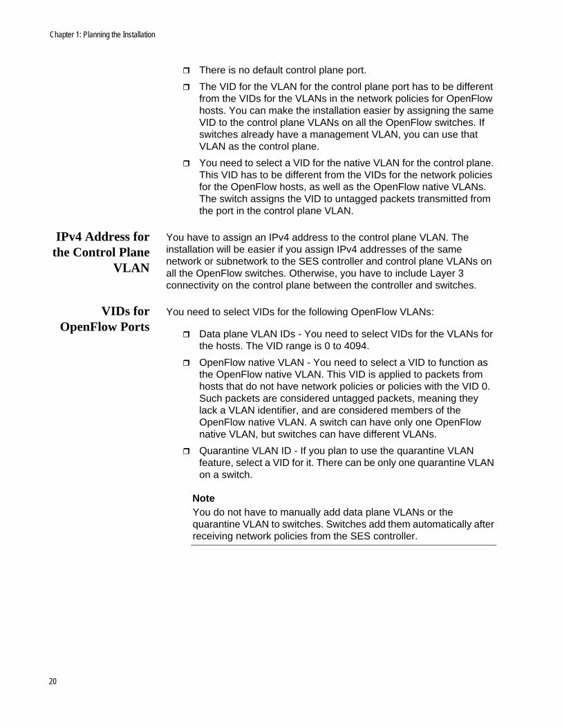
IPv4 Address forthe Control Plane
VLAN
You have to assign an IPv4 address to the control plane VLAN. The installation will be easier if you assign IPv4 addresses of the same network or subnetwork to the SES controller and control plane VLANs on all the OpenFlow switches. Otherwise, you have to include Layer 3 connectivity on the control plane between the controller and switches.
VIDs forOpenFlow Ports
You need to select VIDs for the following OpenFlow VLANs:
Data plane VLAN IDs - You need to select VIDs for the VLANs for the hosts. The VID range is 0 to 4094.
OpenFlow native VLAN - You need to select a VID to function as the OpenFlow native VLAN. This VID is applied to packets from hosts that do not have network policies or policies with the VID 0. Such packets are considered untagged packets, meaning they lack a VLAN identifier, and are considered members of the OpenFlow native VLAN. A switch can have only one OpenFlow native VLAN, but switches can have different VLANs.
Quarantine VLAN ID - If you plan to use the quarantine VLAN feature, select a VID for it. There can be only one quarantine VLAN on a switch.
NoteYou do not have to manually add data plane VLANs or the quarantine VLAN to switches. Switches add them automatically after receiving network policies from the SES controller.
20

SES Controller Installation Guide
Hosts
Hosts are edge devices that are connected to switch ports under OpenFlow management. Here are host examples:
Personal computers
Laptop computers
Wireless tablets
Smart phones
IP surveillance cameras
Badge/security readers
Internet of Things (IoT) sensors, such as temperature or humidity
Factory automation
Lighting
One of the principal functions of the SES controller is to assign hosts to virtual LANs (VLANs). VLANs are identified by IDs (VIDs). This is a number in the range of 0 to 4096. To assign hosts to VLANs on OpenFlow switches, you add network policies with VIDs to the SES controller and then assign the network policies to hosts. Once a host has a network policy, its packets are assigned to the designated VLAN in its policy.
Hosts do not have to have network policies, but they still have to belong to a VLAN. Hosts without network policies or with a policy of VID 0 are automatically assigned to a VLAN referred to as the OpenFlow native VLAN. This VLAN is for hosts that do not otherwise have a VLAN assignment. A switch can have only one OpenFlow native VLAN.
Here are the rules for ingress packets from hosts with network policies:
Packets from hosts to the switches are forwarded inside the switches according to the VIDs defined in the network policies.
Packets transmitted out the upstream port are sent with the VIDs, as tagged packets.
Here are the rules for ingress packets from hosts without network policies or with a policy of VID 0:
Packets from hosts to the switches are forwarded inside the switches as members of the OpenFlow native VLAN.
Packets transmitted out the upstream port are sent without a VID, as untagged packets.
Here are other rules to review:
You should configure hosts to transmit only untagged packets,
21

Chapter 1: Planning the Installation
without VIDs, to switch ports under OpenFlow management. If a switch receives tagged packets from hosts, it removes the VIDs and either replaces them with the VIDs from the appropriate network policies or handles the packets as part of the OpenFlow native VLAN.
Ports under OpenFlow management transmit only untagged packets to hosts. Consequently, hosts have to be capable of handling ingress untagged packets.
22
Chapter 2
Installing the SES Controller on a Server
This chapter includes the following sections:
“Obtaining the SES Controller Application” on page 24
“Installing the SES Controller on a Server” on page 26
NoteFor background information, refer to Chapter 1, “Overview” in the Secure Enterprise Software Defined Networking Controller User Guide.
23

Chapter 2: Installing the SES Controller on a Server
Obtaining the SES Controller Application
This section contains the procedure for downloading the SES controller application from the Software Support web page on the Allied Telesis web site. The procedure requires a computer with a web browser and access to the Internet. To obtain the SES controller application, perform the following procedure:
1. Open your web browser.
2. Click on or enter the following web address in the URL field of your web browser:
http://www.alliedtelesis.com/services-and-support/support/software
The introductory Software Downloads window is shown in Figure 2.
Figure 2. Introductory Software Downloads Window
24
SES Controller Installation Guide
NoteIf you do not have an account on the Download Center, do not continue with this procedure. Instead, click the support portal link in the window and follow the prompts to open an account.
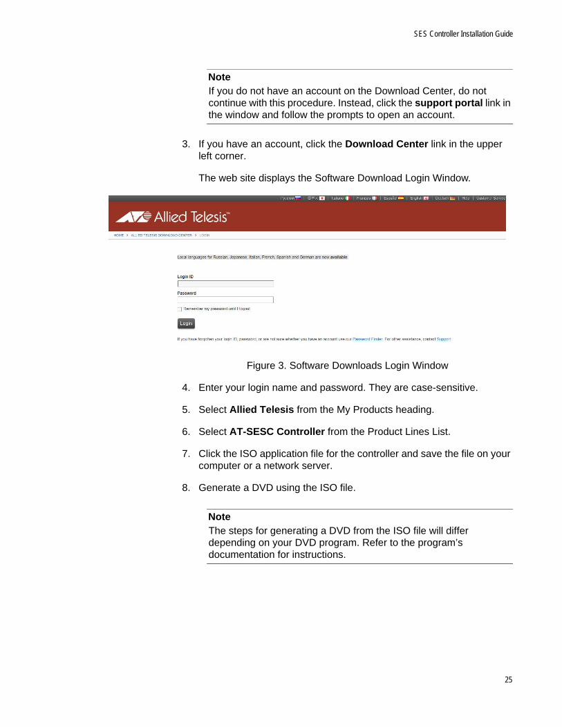
3. If you have an account, click the Download Center link in the upper left corner.
The web site displays the Software Download Login Window.
Figure 3. Software Downloads Login Window
4. Enter your login name and password. They are case-sensitive.
5. Select Allied Telesis from the My Products heading.
6. Select AT-SESC Controller from the Product Lines List.
7. Click the ISO application file for the controller and save the file on your computer or a network server.
8. Generate a DVD using the ISO file.
NoteThe steps for generating a DVD from the ISO file will differ depending on your DVD program. Refer to the program’s documentation for instructions.
25

Chapter 2: Installing the SES Controller on a Server
Installing the SES Controller on a Server
This section contains the procedure for installing the SES controller application on a server. The server requirements are listed in “Server Requirements” on page 16.
Caution
Installing the SES controller deletes all files on the server’s hard disk.
You have to provide the following information during the installation:
IPv4 address and subnet mask for the network interface in the server hardware
IPv4 address of a default gateway
IPv4 addresses of primary and secondary domain name servers (DNS)
Please review the following information before installing the SES controller:
The server must have a video monitor and keyboard.
You must boot the server from the DVD.
The SES controller installation program must be booted in traditional BIOS mode. It does not support UEFI.PC boot loaders.
To install the SES controller, perform the following procedure:
1. Power on the server.
2. Insert the SES controller DVD in the DVD drive.
The installation program displays the prompt in Figure 4.
Figure 4. Starting the Installation Prompt
26

SES Controller Installation Guide
3. Press the Enter key to begin the installation.
The program deletes all the existing files on the hard disk and afterwards copies over the SES controller files from the DVD. At the completion of the file transfer, which may take several minutes, the installation program displays the message in Figure 5.
Figure 5. Choosing Your Management Interface
This window lists the network interfaces in the server. The server has to have at least one interface.
4. Use the up and down arrow keys to select an interface, press the Tab key to select Ok, and press the Enter key.
If the server has more than one interface, you can configure only one during the installation. You can configure additional interfaces after installing the SES controller. For instructions, refer to the Secure Enterprise Software Defined Networking Controller User Guide.
The installation program displays the prompt in Figure 6.
Figure 6. Entering an IP Address
5. Enter an IPv4 address for the server. Press the Tab key to select Ok, and then press the Enter key.
The program displays the prompt in Figure 7 on page 28.
27

Chapter 2: Installing the SES Controller on a Server
Figure 7. Entering a Subnet Mask
6. Enter a subnet mask for the server’s IP address and select OK.
The program displays the prompt in Figure 8.
Figure 8. Entering the Default Gateway
7. Enter the IPv4 address of a default gateway and select OK.
The program displays the prompt in Figure 9.
Figure 9. Entering the IPv4 Address of the Primary Domain Name Server
8. Enter the IPv4 address of a primary domain name server for the server and select OK.
28

SES Controller Installation Guide
The program displays the prompt in Figure 10.
Figure 10. Entering the IP Address of the Secondary Domain Name Server
9. Enter the IPv4 address of a secondary domain name server for the server and select OK.
The program displays the prompt in Figure 11.
Figure 11. Server Settings Installation Window
10. Review the settings. If they are correct, select Correct. If any of the settings are incorrect, select Modify and return to step 4.
The program displays the following message at the completion of the installation:
AT-SESC Install Successfully Finished.Remove Installation DVD and Press [Enter] key to Reboot.
11. Remove the DVD and press the Enter key.
The server reboots. The SES controller installation procedure is complete. Do one of the following:
To configure the switches, perform the instructions in Chapter 3, “Installing OpenFlow Protocol Licenses on Switches” on page 31
29

Chapter 2: Installing the SES Controller on a Server
and Chapter 4, “Configuring Switches for the OpenFlow Protocol” on page 41.
If the switches are already configured, go to Chapter 1, “Overview” in the Secure Enterprise Software Defined Networking Controller User Guide for instructions on performing the first management session with the controller and for guidelines on building your database.
30
Chapter 3
Installing OpenFlow Protocol Licenses on Switches
This chapter contains instructions on how to install subscription licenses for the OpenFlow protocol on Allied Telesis switches. Please review the information in “OpenFlow Switches” on page 18 before performing the following procedures. This chapter includes the following sections:
“Introduction” on page 32
“Displaying a Switch’s Serial Number” on page 33
“Automatically Downloading a License to a Switch” on page 34
“Manually Downloading a License to a Switch” on page 35
“Activating a Subscription License” on page 39
31
Chapter 3: Installing OpenFlow Protocol Licenses on Switches
Introduction
The OpenFlow protocol comes standard with the AlliedWare Plus operating system, but deactivated. Activating it requires a subscription license from the Download Center on the Allied Telesis web site. A subscription license is a Capability Response File (CRF) in a BIN format that has to be downloaded from the Download Center to the flash memory in a switch. Refer to Table 1 on page 18 for a list of available licenses.
Subscription licenses are based on the serial numbers of the switches. They only operate on devices with matching serial numbers. Consequently, purchasing a subscription license requires knowing the switch’s serial number and providing it to Allied Telesis. This is explained in “Displaying a Switch’s Serial Number” next.
Once you have purchased a subscription license for the protocol, you have to download it from the Download Center web site and install it in the flash memory of a switch. There are two ways to do this. One way is automatically with the LICENSE UPDATE ONLINE command in the AlliedWare Plus operating system. The command downloads the license from the Download Center and stores it in a switch’s flash memory. For instructions, refer to “Automatically Downloading a License to a Switch” on page 34.
The other way to download a license to a switch is to do it manually. This involves going to the Download Center web site, obtaining the license, and then downloading it to the switch. For instructions, refer to “Manually Downloading a License to a Switch” on page 35.
For further information on subscription licenses, refer to the Licensing: Feature Overview and Configuration Guide at this Allied Telesis web site.
http://www.alliedtelesis.com/library/search//type/document
32

SES Controller Installation Guide
Displaying a Switch’s Serial Number
The first step to ordering a subscription license for the OpenFlow protocol is obtaining a switch’s serial number. You can find it on a label on the bottom panel of the device or view it with the SHOW SYSTEM SERIALNUMBER command, as explained here:
1. Start a local or remote management session with the switch. For instructions, refer to the appropriate Installation Guide.
2. In the User Exec mode enter the SHOW SYSTEM SERIALNUMBER command. Here is an example of the command:
awplus> show system serialnumberA05050G149801293
3. Contact your authorized Allied Telesis representative and provide the device’s serial number to purchase the license.
4. Once the license becomes available on the Download Center, perform “Automatically Downloading a License to a Switch” next or “Manually Downloading a License to a Switch” on page 35.
33

Chapter 3: Installing OpenFlow Protocol Licenses on Switches
Automatically Downloading a License to a Switch
The following procedure explains how to use the LICENSE UPDATE ONLINE command to automatically download a license from the Download Center to the flash memory of a switch. The procedure assumes the following:
You have a Download Center account.
The license for the switch exists in your Download Center account.
The switch has a connection to the Internet.
To automatically download a license to a switch from the Download Center, perform the following procedure:
1. Start a local or remote management session with the switch. For instructions, refer to the appropriate Installation Guide.
2. Enter the ENABLE command to move from the User Exec mode to the Privileged Exec mode.
awplus> enableawplus#
3. Enter the LICENSE UPDATE ONLINE command.
awplus# license update online
The switch performs the following steps:
Connects to the Download Center.
Checks if new or changed licenses are available for the device, based on the device’s serial number.
Downloads and installs the licenses.
The update process normally takes approximately five seconds. If the console does not respond for ten or more seconds after typing the command, a network, routing or firewall configuration error is probably preventing the connection from establishing. If this happens, abort the command by pressing Ctrl-C, or wait for the command to time out after 30 seconds.
If the update is successful, the device produces log messages indicating which feature licenses have been updated (activated, deactivated, or expiration/count changed). If the command completes successfully but there are no available licenses or there is no change in the licenses already on the device, no log messages are produced.
4. Activate the license. For instructions, go to “Activating a Subscription License” on page 39.
34

SES Controller Installation Guide
Manually Downloading a License to a Switch
This procedure explains how to manually obtain a license from the Download Center and download it to the flash memory of a switch. The procedure assumes the following:
You have a Download Center account.
You purchased the license using the switch’s serial number.
To manually download a license to a switch, perform the following procedure:
1. Start your web browser.
2. Enter the following path in the URL field:
www.alliedtelesis.com/support/software
3. Click the Download Center link. Refer to Figure 12.
Figure 12. Download Center Web Site
The web site displays the login window. Refer to Figure 13 on page 36.
Download Center link
35

Chapter 3: Installing OpenFlow Protocol Licenses on Switches
Figure 13. Download Center Login Prompts
4. Enter you login ID and password. They are case-sensitive.
5. To locate your device type, click Search Devices from the Devices menu in the left column of the window. Refer to Figure 14.
Figure 14. Search Devices Window
6. To select a specific license, click its serial number from the Serial Number list.
The Download Center displays the View Device window for the license. An example is shown in Figure 15 on page 37.
36

SES Controller Installation Guide
Figure 15. View Device Window
7. Click the Download Capability Response link.
The Download Center displays the prompt in Figure 16.
Figure 16. Prompt for Saving the License
8. Click the Save File option.
9. Enter a filename for the license and a location on your network or computer to store the file. The default filename is the switch’s serial number. Do not change the BIN extension.
10. Start a local or remote management session on the switch. For instructions, refer to the appropriate Installation Guide.
37
Chapter 3: Installing OpenFlow Protocol Licenses on Switches
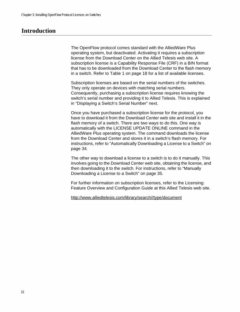
11. Copy the license from your network or computer to the flash memory in the switch.
You can copy the license to the switch several ways. For example, you can store the file on a USB device, insert the device into the USB port in the switch, and then copy the file with the COPY command. For example:
awplus# copy usb flashEnter source path with file name[}:A050373903.binCopying...Successful operation
Alternatively, you can copy the license from a TFTP server. In the following example, the TFTP server has the IP address 10.201.43.128
awplus# copy tftp flashEnter source host name []: 10.210.43.128Enter source path with file name []:A050373903.binEnter destination file name [A050373903.bin]:Copying...Successful operation
12. After copying the license to the switch, activate it with the instructions in “Activating a Subscription License” next.
38

SES Controller Installation Guide
Activating a Subscription License
Once a subscription license is stored in the switch’s flash memory, you have to activate it with the LICENSE UPDATE command. To activate a license, perform the following procedure:
1. In the Privileged Exec mode, enter the DIR command to view the BIN files in the flash memory of the switch: Here is an example:
awplus# dir *.bin2386 -rwx Sep 24 2017 10:20:54 flash:/A050373903.bin
2. Activate the license with the LICENSE UPDATE command. The command has the following format:
license update <url.bin>
Here is an example:
awplus# license update A050373903.bin
The command copies license entitlements in the CRF file to the device’s internal encrypted license library. The command does not display a confirmation message.
3. To confirm the activation, enter the SHOW LICENSE EXTERNAL command.
4. After confirming the activation, you can delete the CRF file from the switch. This step is optional.
The OpenFlow protocol license is now installed and activated on the switch.
5. Go to Chapter 4, “Configuring Switches for the OpenFlow Protocol” on page 41.
39

Chapter 3: Installing OpenFlow Protocol Licenses on Switches
40

Chapter 4
Configuring Switches for the OpenFlow Protocol
This chapter contains instructions on how to configure Allied Telesis switches for the OpenFlow protocol and the SES controller. Please review the information in “OpenFlow Switches” on page 18 before performing the following procedures. This chapter includes the following sections:
“Introduction” on page 42
“General Steps” on page 44
“Example of Configuring a Switch” on page 47
“Verifying a Switch’s Configuration” on page 52
41

Chapter 4: Configuring Switches for the OpenFlow Protocol
Introduction
The procedures in the following sections explain how to configure Allied Telesis switches for the OpenFlow protocol and SES controller. Please review the information in “OpenFlow Switches” on page 18 before performing the procedures. For additional information, refer to the OpenFlow Protocol: Feature Overview and Configuration Guide at this Allied Telesis web site.
http://www.alliedtelesis.com/library/search//type/document
Caution
Configuring a switch for the OpenFlow protocol requires resetting the device. Performing the procedure on an active switch will interrupt network operations.
NoteThe SES controller and OpenFlow protocol are intended for edge switches. They should not be used on network core devices.
You should decide on the requirements in Table 2 before configuring a switch for the protocol:
Table 2. Switch Port and VID Requirements
Requirement Description
OpenFlow data plane ports Which switch ports will be connected to hosts and managed with the OpenFlow protocol?
Upstream port or static channel aggregator
Which switch interface will be connected to a higher network level device, such as a router or other Layer 3 device? It can be a single port or a static channel aggregator. The interface, like the data plane ports, must use the OpenFlow protocol. A switch can have only one upstream interface.
Control plane port Which switch interface will function as the connection to the control plane and SES controller? It can be a single port or a static or dynamic channel aggregator. It cannot use the OpenFlow protocol.
42

SES Controller Installation Guide
NoteFor background information, refer to “OpenFlow Switches” on page 18 or Chapter 1, “Overview,” in the Secure Enterprise Software Defined Networking Controller User Guide.
NoteYou do not have to manually add data plane VLANs or the quarantine VLAN to OpenFlow switches. Switches add them automatically after receiving network policies with the VIDs from the SES controller.
IPv4 address for the control plane VLAN
What will be the IPv4 address of the control plane VLAN, leading to the SES controller?
VIDs for the data plane VLANs
What will be the VIDs for the data plane VLANs for the hosts on ports under OpenFlow control?
VID for the control plane port or static channel aggregator
What will be the VID for the VLAN for the switch interface to the control plane and SES controller? Different switches can use the same VID for their control plane VLANs.
VID for the OpenFlow native VLAN for host ports
What will be the VID for the OpenFlow native VLAN? This VLAN is for hosts that are not assigned network policies or have a policy with the VID 0. A switch can have only one OpenFlow native VLAN.
VID for the native VLAN for the control plane port
What will be the VID for untagged packets on the native VLAN of the control plane?
VID for the quarantine VLAN
What will be VID for the quarantine VLAN for hosts that violate location or schedule policies? It has to be different from the other VIDs. A switch can have only one quarantine VLAN.
Datapath ID What will be the unique datapath ID for the switch? The SES controller identifies the switch by this number. It consists of 16 hexadecimal digits. The default is the switch’s MAC address preceded by four zeros (0000).
Table 2. Switch Port and VID Requirements (Continued)
Requirement Description
43

Chapter 4: Configuring Switches for the OpenFlow Protocol
General Steps
This section contains the general steps to configuring switches for the OpenFlow protocol. Please review the following information before performing the steps:
You should have already obtained and installed an OpenFlow subscription license on the switch. For instructions, refer to Chapter 3, “Installing OpenFlow Protocol Licenses on Switches” on page 31.
You should not use the OpenFlow protocol with the VCStack feature.
The procedures disable the spanning tree protocol. If the switch is connected to a live network, you should use the SHOW SPANNING-TREE BRIEF command in the AlliedWare Plus operating system to determine whether any ports are blocking network loops. Disabling spanning tree when there are network loops can result in broadcast storms and reduced network performance. Refer to the appropriate Software Reference Guide for further information.
The steps are divided into two phases:
Phase 1: General Steps
Phase 2: OpenFlow Protocol Steps
Table 3 contains the steps to Phase 1, General Steps.
Table 3. Phase 1 - General Steps
Step Task AlliedWare Plus Command
1 Start a local or remote management session on the switch.
For instructions, refer to the appropriate Installation Guide.
2 Verify the version number of the AlliedWare Plus operating system. The version must be v5.4.7 or newer.
SHOW VERSION command in the User Exec or Privileged Exec mode.
3 Disable the VCStack feature. NO STACK command in the Global Configuration mode.
4 Disable the Spanning Tree feature.
NO SPANNING-TREE command in the Global Configuration mode.
5 Save the configuration. WRITE command in the Privileged Exec mode.
44

SES Controller Installation Guide
Table 4 contains the steps for Phase 2, OpenFlow Protocol Steps.
6 Reboot the switch. REBOOT command in the Privileged Exec mode.
Table 4. Phase 2 - OpenFlow Protocol Steps
Step Task AlliedWare Plus Command
1 Start a new local or remote management session on the switch.
For instructions, refer to the appropriate Installation Guide.
2 Add OpenFlow management to the host ports and upstream interface.
OPENFLOW command in the interface mode of the host ports and upstream interface.
3 Add the following VLANs:
- Control port VLAN
- Control plane native VLAN
- OpenFlow native VLAN.
You do not have to add data plane VLANs or the quarantine VLAN. The switch adds them automatically after receiving network policies with their VIDs from the SES controller.
VLAN command in the VLAN Configuration mode.
4 Add an IPv4 address to the control plane VLAN.
IP ADDRESS in the VLAN Interface Configuration mode.
5 Add the control plane port to the control plane VLAN.
SWITCHPORT TRUNK ALLOWED VLAN command in the Interface Configuration mode of the port.
6 Specify the native VLAN for the control plane.
SWITCHPORT TRUNK NATIVE VLAN command in the Interface mode of the ports in the control plane.
7 Designate the OpenFlow native VLAN for the host ports and upstream interface.
OPENFLOW NATIVE VLAN command in the Global Configuration mode.
Table 3. Phase 1 - General Steps (Continued)
Step Task AlliedWare Plus Command
45

Chapter 4: Configuring Switches for the OpenFlow Protocol
Here are a couple notes:
The switch comes with a default VLAN, with the VID 1. You can use it as part of the configuration, such as for the control plane VLAN.
Changing a switch’s datapath ID is optional. The default datapath ID is a switch’s MAC address preceded by four zeros (0000). If you do decide to change it, you should do so before specifying the IP address of the SES controller’s server on the switch. Otherwise, the server might end up with two entries for the same switch, one with the default datapath ID, which would be invalid because it was replaced, and another with the new datapath ID.
8 Change the datapath ID value on the switch.
OPENFLOW DATAPATH-ID command in the Global Configuration mode. This step is optional.
9 Add the IP address and TCP port number of the server with the SES controller’s.
OPENFLOW CONTROLLER command in the Global Configuration mode.
10 Disable the IGMP Snooping TCN Query Solicitation feature.
NO IGMP SNOOPING TCN QUERY SOLICIT command in the Interface mode of the host VLANs.
11 Save the configuration. WRITE command in the Privileged Exec mode.
12 Reboot the switch. REBOOT command in the Privileged Exec mode.
Table 4. Phase 2 - OpenFlow Protocol Steps (Continued)
Step Task AlliedWare Plus Command
46
SES Controller Installation Guide
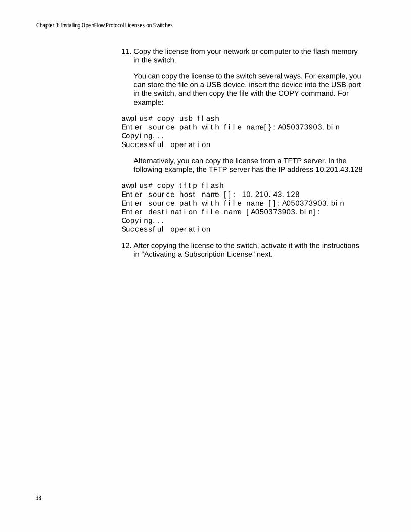
Example of Configuring a Switch
Here is an example of how to configure a switch for the OpenFlow protocol and the SES controller. Here are the specifications:
Switch model: AT-x310-26FT
OpenFlow host ports: port1.0.1 to port1.0.24
Upstream port: port1.0.25
Control plane port: port1.0.26
Control plane VID: 90
Control plane native VLAN VID: 101
OpenFlow native VLAN VID: 102
IPv4 address and subnet mask for the control plane VLAN: 10.121.1.123/24
Datapath ID: 0000000000000014
IPv4 address and TCP port number of the SES controller: 10.121.1.45 and 6653
Table 5 on page 47 contains the steps to phase 1, General Steps.
Table 5. Example of Phase 1 - General Steps
AlliedWare Plus Command Description
The first series of commands starts a management session on the switch and verifies the AlliedWare Plus version number.
Start a local or remote management session on the switch. For instructions, refer to the appropriate Installation Guide.
awplus> enableawplus#
Move from the User Exec mode to the Privileged Exec mode.
awplus# show versionAlliedWare Plus (TM) 5.4.7..awplus#
Display the version number of the AlliedWare Plus operating system on the switch. The version must be v5.4.7 or newer. Upgrade the system if the operating system is older than v5.4.7.
awplus# configure terminalEnter configuration commands, one per line. End with CNTL/Z.
Move to the Global Configuration mode.
47

Chapter 4: Configuring Switches for the OpenFlow Protocol
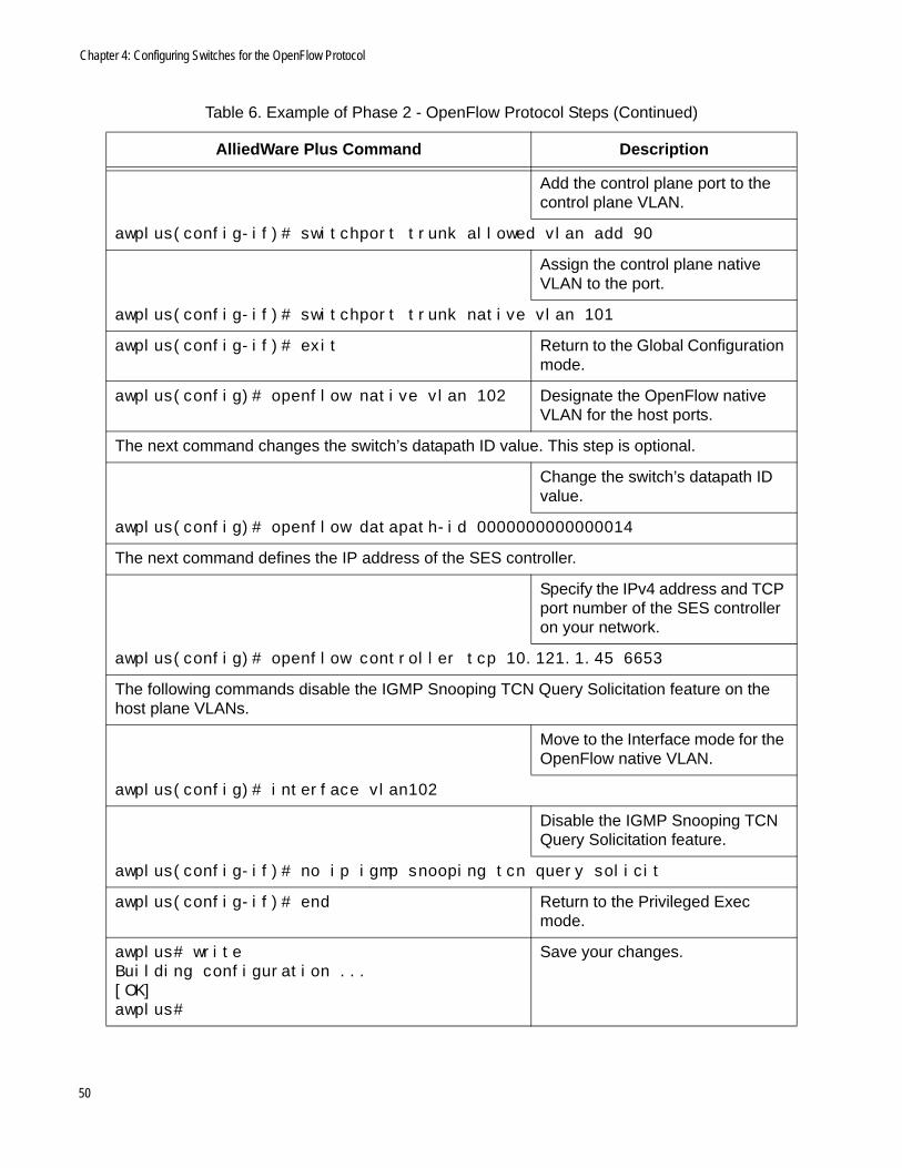
Table 6 contains the steps to phase 2, OpenFlow Protocol Steps.
This series of commands disables the VCStack and xSTP features.
awplus(config)# no stack enable% The device needs to be restarted for this change to take effect.
Disable VCStack.
awplus(config)# no spanning-tree enable Disable xSTP.
awplus(config)# exit Return to the Privileged Exec mode.
awplus# writeBuilding configuration ...[OK]
Save your changes. If this is the first management session of the switch, the WRITE command automatically adds to flash memory a new configuration file called DEFAULT.CFG for storing your configuration changes.
awplus# rebootreboot system? (y/n):
Reboot the switch with the REBOOT command.
Type “Y” for yes.
Wait for the switch to initialize its management software.
Table 5. Example of Phase 1 - General Steps (Continued)
AlliedWare Plus Command Description
Table 6. Example of Phase 2 - OpenFlow Protocol Steps
AlliedWare Plus Command Description
The first series of commands starts a management session on the switch and moves to the Global Configuration mode.
Start a new local or remote management session on the switch.
awplus> enableawplus#
Move from the User Exec mode to the Privileged Exec mode.
awplus# configure terminalEnter configuration commands, one per line. End with CNTL/Z.
Move to the Global Configuration mode.
48

SES Controller Installation Guide
The following commands add the OpenFlow protocol to the host and upstream ports.
Move to the interface mode of the host and upstream ports.
awplus(config)# interface port1.0.1-port1.0.25
awplus(config-if)# openflow Add OpenFlow management to the ports.
awplus(config-if)# exit Return to the Global Configuration mode.
The following commands add the VIDs for the control and native VLANs.
awplus(config)# vlan database Move to the VLAN Configuration mode.
Add the control plane VLAN, control plane native VLAN, and OpenFlow native VLAN.
awplus(config-vlan)# vlan 90 name control_vlan state enableawplus(config-vlan)# vlan 101 name control_native_vlan state enableawplus(config-vlan)# vlan 102 name OpenFlow_native_vlan state enable
awplus(config-vlan)# exit Return to the Global Configuration mode.
The following commands assign the IPv4 address to the control plane VLAN.
awplus(config)# interface vlan90 Move to the Interface Configuration mode of the control plane VLAN.
Assign an IPv4 address to the control plane VLAN.
awplus(config-if)# ip address 10.121.1.123/24
awplus(config-if)# exit Return to the Global Configuration mode.
The following commands add the control plane port to the control plane VLAN and designate the native VLAN.
awplus(config)# interface port1.0.26 Move to the Interface mode for the control plane port.
Table 6. Example of Phase 2 - OpenFlow Protocol Steps (Continued)
AlliedWare Plus Command Description
49
Chapter 4: Configuring Switches for the OpenFlow Protocol
Add the control plane port to the control plane VLAN.
awplus(config-if)# switchport trunk allowed vlan add 90
Assign the control plane native VLAN to the port.
awplus(config-if)# switchport trunk native vlan 101
awplus(config-if)# exit Return to the Global Configuration mode.
awplus(config)# openflow native vlan 102 Designate the OpenFlow native VLAN for the host ports.
The next command changes the switch’s datapath ID value. This step is optional.
Change the switch’s datapath ID value.
awplus(config)# openflow datapath-id 0000000000000014
The next command defines the IP address of the SES controller.
Specify the IPv4 address and TCP port number of the SES controller on your network.
awplus(config)# openflow controller tcp 10.121.1.45 6653
The following commands disable the IGMP Snooping TCN Query Solicitation feature on the host plane VLANs.
Move to the Interface mode for the OpenFlow native VLAN.
awplus(config)# interface vlan102
Disable the IGMP Snooping TCN Query Solicitation feature.
awplus(config-if)# no ip igmp snooping tcn query solicit
awplus(config-if)# end Return to the Privileged Exec mode.
awplus# writeBuilding configuration ...[OK]awplus#
Save your changes.
Table 6. Example of Phase 2 - OpenFlow Protocol Steps (Continued)
AlliedWare Plus Command Description
50

SES Controller Installation Guide
awplus# rebootreboot system? (y/n):awplus#
Reboot the switch.
Type “Y” for yes.
Wait for the switch to initialize its management software.
Table 6. Example of Phase 2 - OpenFlow Protocol Steps (Continued)
AlliedWare Plus Command Description
51

Chapter 4: Configuring Switches for the OpenFlow Protocol
Verifying a Switch’s Configuration
To confirm the configuration of the switch for the OpenFlow protocol, perform the following procedure:
1. Start a management session on the SES controller. For instructions, refer to the SES Controller User Guide.
2. Select OpenFlow Switch -> Active OpenFlow Switch List.
The SES controller displays the Active OpenFlow Switch List window. An example is shown in Figure 17. Switches are identified by their unique datapath IDs. A switch’s default datapath ID is its MAC address preceded by four zeros (0000).
Figure 17. Active OpenFlow Switch List Window
The window should include all switches on which you activated and configured the OpenFlow protocol.
3. Verify that the new switch is included in the list. It should have a Register button in the right column indicating it has not been registered yet.
NoteFor instructions on performing the first management session or for guidelines on how to begin building your database of switches and hosts, refer to Chapter 1, “Overview” in the Secure Enterprise Software Defined Networking Controller User Guide.
52
Chapter 5
Configuring Palo Alto Networks Firewalls
This chapter includes the following sections:
“Introduction” on page 54
“Adding a Syslog Server Profile” on page 55
“Adding a Custom Log Format” on page 57
“Adding a Log Forwarding Profile” on page 59
“Adding a Security Policy Rule” on page 60
53

Chapter 5: Configuring Palo Alto Networks Firewalls
Introduction
This chapter contains the procedures for configuring Palo Alto Networks Next Generation Firewalls series (PA-xx) for the enhanced firewall protection feature of the SES controller. The procedures configure firewalls to send syslog messages to the SES controller when they detect viruses or malware attacks on their WAN ports. The SES controller responds to the syslog messages by instructing switches to disable affected switch ports or move ports to quarantine VLANs to mitigate attacks. For more information, refer to Chapter 1, “Overview,” in the Secure Enterprise Software Defined Networking Controller User Guide.
NotePalo Alto Networks Next Generation Firewalls must have PAN-OS-7.0 or newer software.
NoteThe enhanced firewall protection feature requires a trap monitoring rule file from Allied Telesis. The file has to be installed on the SES controller. For instructions, refer to the Secure Enterprise Software Defined Networking Controller User Guide.
54

SES Controller Installation Guide
Adding a Syslog Server Profile
To add a syslog server profile to the firewall, perform the following procedure.
1. Start a management session the firewall. For instructions, refer to the appropriate Palo Alto Networks documentation.
2. Select Device -> Server Profiles -> Syslog. Refer to Figure 18 on page 56.
3. Click Add at the bottom of the Device tab.
4. Click Add in the Syslog Server Profile window.
5. Configure the values for the new syslog profile. Refer to Table 7.
6. Go to “Adding a Custom Log Format” on page 57.
Table 7. Network List Window
Value Description
Name Enter a unique name for the profile. Allied Telesis recommends “SESC_SERVER”.
Syslog Server Enter the IPv4 address of the SES controller.
Port Enter the UDP port number for the syslog messages. This value must be the same on both the firewall and SES controller. Both devices use the same default value, 514.
Format Select BSD, the default, for the syslog packet format.
Facility Select LOG_USER, the default, for the facility. This value is used to calculate the priority (PRI) field.
55

Chapter 5: Configuring Palo Alto Networks Firewalls
Figure 18. Adding a Syslog Server Profile
Step 2
Step 2Step 2
Step 3
Step 4
Step 5
56

SES Controller Installation Guide
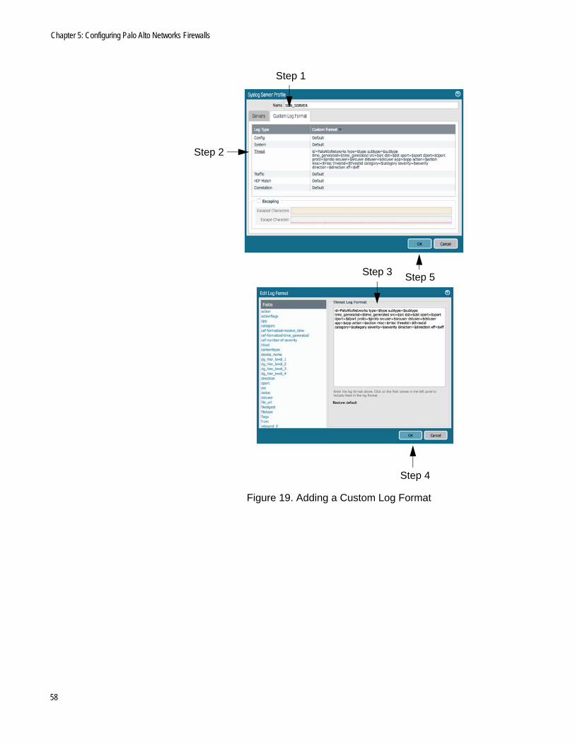
Adding a Custom Log Format
To add a custom log format, perform the following procedure:
1. Click the Custom Log Format tab. Refer to Figure 19 on page 58.
2. Click Threat.
3. Copy and paste the following text into the Edit Log Format window.
id=PaloAltoNetworks type=$type subtype=$subtype time_generated=$time_generated src=$src dst=$dst sport=$sport dport=$dport proto=$proto srcuser=$srcuser dstuser=$dstuser app=$app action=$action misc=$misc threatid=$threatid category=$category severity=$severity direction=$direction xff=$xff
4. Click the Ok button in the Edit Log Format window to close the window.
5. Click the Ok button in the Syslog Server Profile window to close the window.
6. Go to “Adding a Log Forwarding Profile” on page 59.
57
Chapter 5: Configuring Palo Alto Networks Firewalls
Figure 19. Adding a Custom Log Format
Step 1
Step 3
Step 2
Step 4
Step 5
58
SES Controller Installation Guide
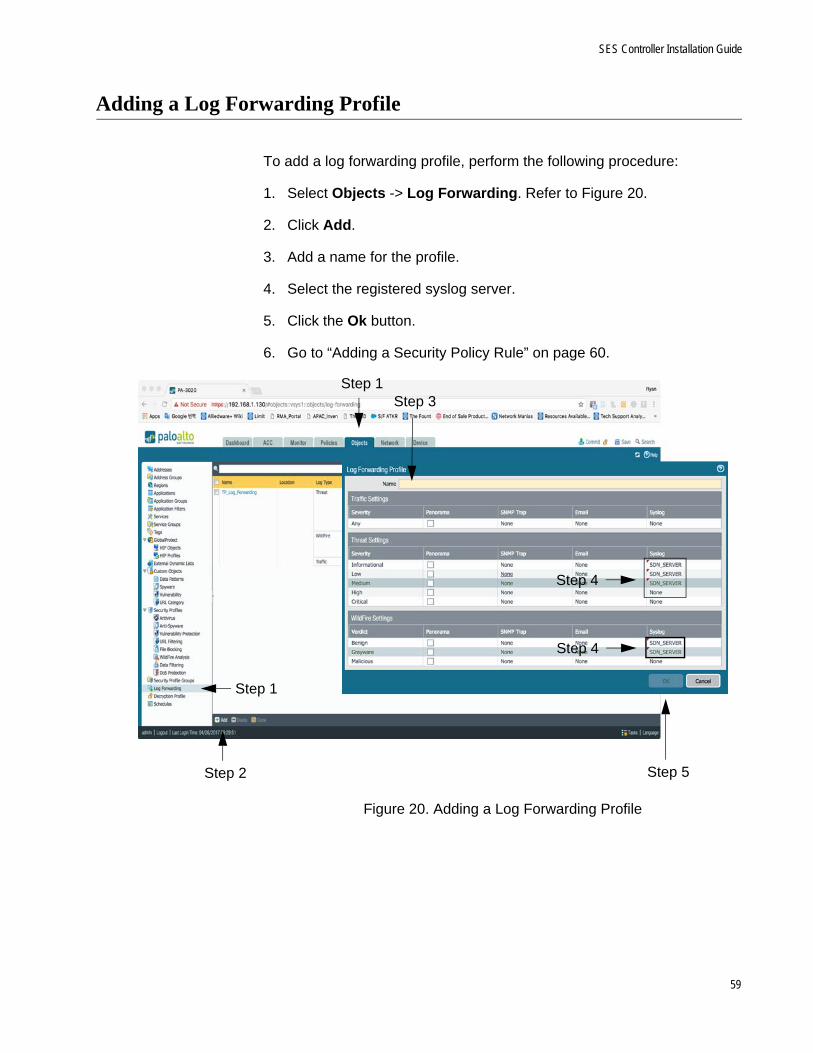
Adding a Log Forwarding Profile
To add a log forwarding profile, perform the following procedure:
1. Select Objects -> Log Forwarding. Refer to Figure 20.
2. Click Add.
3. Add a name for the profile.
4. Select the registered syslog server.
5. Click the Ok button.
6. Go to “Adding a Security Policy Rule” on page 60.
Figure 20. Adding a Log Forwarding Profile
Step 1
Step 1
Step 2
Step 3
Step 4
Step 4
Step 5
59

Chapter 5: Configuring Palo Alto Networks Firewalls
Adding a Security Policy Rule
To add a security policy rule, perform the following procedure:
1. Select Policies -> Security. Refer to Figure 21.
2. Click Add.
3. Click the Actions tab.
4. From the Log Forwarding pull-down menu, select TP_Log_Forwarding.
5. Configure profile.
6. Click the Ok button.
NoteAfter completing this procedure, go to the Secure Enterprise Software Defined Networking Controller User Guide for instructions on how to upload the trap monitoring rule file to the controller.
Figure 21. Adding a Security Policy Rule
Step 6
Step 4
Step 1
Step 2
Step 1
Step 3
Step 5
60