section - erikseriks.nl/documentatie/mechanische-aandrijftechniek/producten...section shaft fixings...
TRANSCRIPT

SH
AFT
FIX
ING
SS
ecti
on
SHAFT FIXINGS 6
Drive Design & Maintenance Manual 123
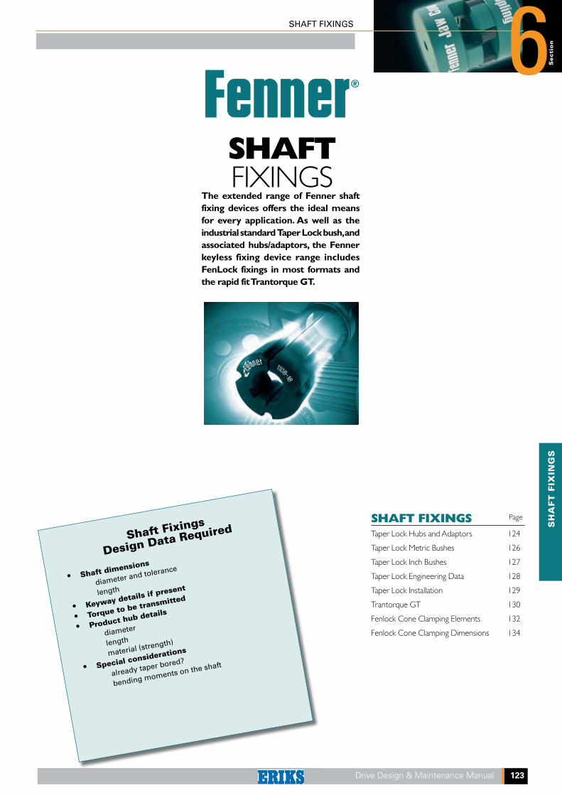
The extended range of Fenner shaft fixing devices offers the ideal means for every application. As well as the industrial standard Taper Lock bush, and associated hubs/adaptors, the Fenner keyless fixing device range includes FenLock fixings in most formats and the rapid fit Trantorque GT.
SHAFT FIXINGSTaper Lock Hubs and Adaptors 124
Taper Lock Metric Bushes 126
Taper Lock Inch Bushes 127
Taper Lock Engineering Data 128
Taper Lock Installation 129
Trantorque GT 130
Fenlock Cone Clamping Elements 132
Fenlock Cone Clamping Dimensions 134
Page
SHAFTFIXINGS
Shaft Fixings
Design Data Required
• Shaft dimensions
diameter and tolerance
length
• Keyway details if present
• Torque to be transmitted
• Product hub details
diameter
length
material (strength)
• Special considerations
already taper bored?
bending moments on the shaft
SHAFT FIXINGS
6
124 Drive Design & Maintenance Manual
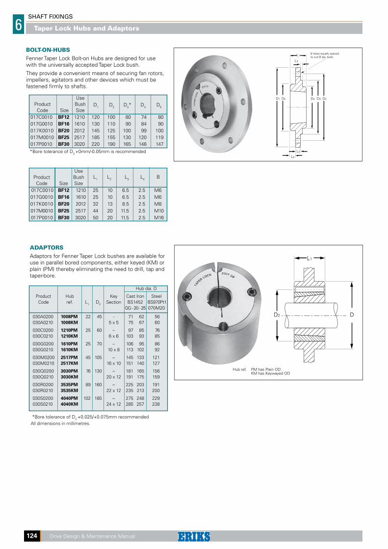
Taper Lock Hubs and Adaptors
*Bore tolerance of D3 +0.025/+0.075mm recommendedAll dimensions in millimetres.
Use Product Bush Code Size Size
L1 L2 L3 L4 B
017C0010 BF12 1210 25 10 6.5 2.5 M6 017G0010 BF16 1610 25 10 6.5 2.5 M6 017K0010 BF20 2012 32 13 8.5 2.5 M8 017M0010 BF25 2517 44 20 11.5 2.5 M10 017P0010 BF30 3020 50 20 11.5 2.5 M16
Use Product Bush Code Size Size
D1 D2 D3* D4 D5
017C0010 BF12 1210 120 100 80 74 80 017G0010 BF16 1610 130 110 90 84 90 017K0010 BF20 2012 145 125 100 99 100 017M0010 BF25 2517 185 155 130 120 119 017P0010 BF30 3020 220 190 165 146 147 *Bore tolerance of D3 +0mm/-0.05mm is recommended
BOLT-ON-HUBSFenner Taper Lock Bolt-on Hubs are designed for use with the universally accepted Taper Lock bush.
They provide a convenient means of securing fan rotors, impellers, agitators and other devices which must be fastened firmly to shafts.
D3D4 D2D5D1
L4
L1
L3
L2
6 holes equally spacedto suit B dia. bolts
ADAPTORSAdaptors for Fenner Taper Lock bushes are available for use in parallel bored components, either keyed (KM) or plain (PM) thereby eliminating the need to drill, tap and taper-bore.
Hub dia. D
Product Hub Key Cast Iron Steel Code ref. L1 D2 Section BS1452 BS970Pt1 GG - 20 - 25 070M20
030A0200 1008PM 22 45 - 71 62 56 030A0210 1008KM 5 x 5 75 67 60
030C0200 1210PM 25 60 – 97 85 76 030C0210 1210KM 6 x 6 103 93 85
030G0200 1610PM 25 70 – 106 95 86 030G0210 1610KM 10 x 8 113 102 92
030M0200 2517PM 45 105 – 145 133 121 030M0210 2517KM 16 x 10 151 140 127
030Q0200 3030PM 76 130 – 181 165 156 030Q0210 3030KM 20 x 12 191 175 159
030R0200 3535PM 89 160 – 225 203 191 030R0210 3535KM 22 x 12 235 213 200
030S0200 4040PM 102 185 – 275 248 229 030S0210 4040KM 24 x 12 285 257 238
L1
DD2
Hub ref. PM has Plain OD KM has Keywayed OD
SH
AFT
FIX
ING
SS
ecti
on
SHAFT FIXINGS 6
Drive Design & Maintenance Manual 125
Taper Lock Hubs and Adaptors
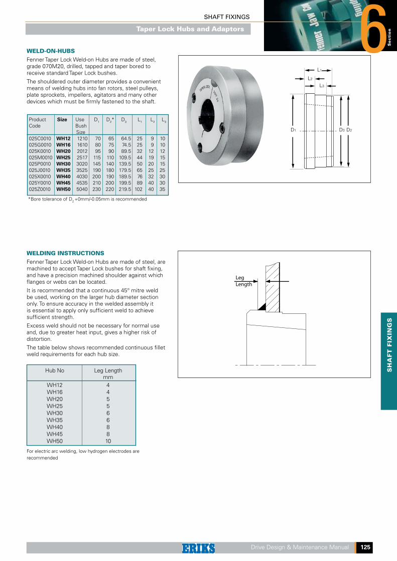
WELD-ON-HUBSFenner Taper Lock Weld-on Hubs are made of steel, grade 070M20, drilled, tapped and taper bored to receive standard Taper Lock bushes.
The shouldered outer diameter provides a convenient means of welding hubs into fan rotors, steel pulleys, plate sprockets, impellers, agitators and many other devices which must be firmly fastened to the shaft.
*Bore tolerance of D2 +0mm/-0.05mm is recommended
Product Size Use D1 D2* D3 L1 L2 L3
Code Bush Size025C0010 WH12 1210 70 65 64.5 25 9 10025G0010 WH16 1610 80 75 74.5 25 9 10025K0010 WH20 2012 95 90 89.5 32 12 12025M0010 WH25 2517 115 110 109.5 44 19 15025P0010 WH30 3020 145 140 139.5 50 20 15025J0010 WH35 3525 190 180 179.5 65 25 25025X0010 WH40 4030 200 190 189.5 76 32 30025Y0010 WH45 4535 210 200 199.5 89 40 30025Z0010 WH50 5040 230 220 219.5 102 40 35
D3 D2D1
L1
L3
L2
WELDING INSTRUCTIONSFenner Taper Lock Weld-on Hubs are made of steel, are machined to accept Taper Lock bushes for shaft fixing, and have a precision machined shoulder against which flanges or webs can be located.
It is recommended that a continuous 45° mitre weld be used, working on the larger hub diameter section only. To ensure accuracy in the welded assembly it is essential to apply only sufficient weld to achieve sufficient strength.
Excess weld should not be necessary for normal use and, due to greater heat input, gives a higher risk of distortion.
The table below shows recommended continuous fillet weld requirements for each hub size.
Hub No Leg Length mm WH12 4 WH16 4 WH20 5 WH25 5 WH30 6 WH35 6 WH40 8 WH45 8 WH50 10
For electric arc welding, low hydrogen electrodes are recommended

SHAFT FIXINGS
6
126 Drive Design & Maintenance Manual
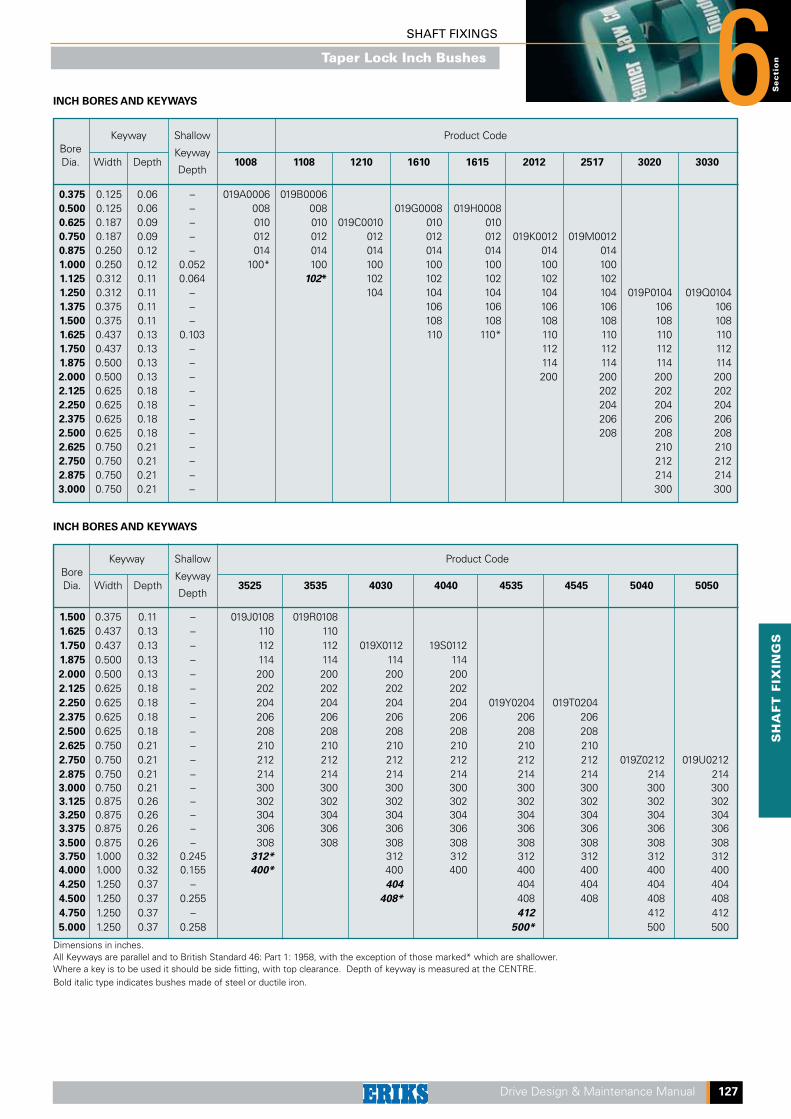
Keyway Shallow Product Code Bore Dia. Width Depth
Keyway 3525 3535 4030 4040 4535 4545 5040 5050
Depth
35 10 3.3 – 029J0035 029R0035 38 10 3.3 – 038 038 40 12 3.3 – 040 040 029X0040 029S0040 42 12 3.3 – 042 042 042 042 45 14 3.8 – 045 045 045 045 48 14 3.8 – 048 048 048 048 50 14 3.8 – 050 050 050 050 55 16 4.3 – 055 055 055 055 029Y0055 029T0055 60 18 4.4 – 060 060 060 060 060 060 65 18 4.4 – 065 065 065 065 065 065 70 20 4.9 – 070 070 070 070 070 070 029Z0070 029U0070 75 20 4.9 – 075 075 075 075 075 075 075 075 80 22 5.4 – 080 080 080 080 080 080 080 080 85 22 5.4 – 085 085 085 085 085 085 085 085 90 25 5.4 – 090 090 090 090 090 090 090 090 95 25 5.4 – 095 095 095 095 095 095 095 100 28 6.4 4.4 100* 100 100 100 100 100 100 105 28 6.4 – 105 105 105 105 105 110 28 6.4 – 110 110 110 110 110 115 32 7.4 5.4 115* 115 115 115 120 32 7.4 – 120 120 120 125 32 7.4 – 125 125 125
Dimensions in millimetres.Keyways are British Standard Metric BS 4235: Part 1: 1972 DIN 6885 and conform to ISO recommendations with the exception of those marked* which are shallower. Where a key is to be used it should be parallel and side fitting, with top clearance. Depth of keyway is measured at the CENTRE.Bold italic type indicates bushes made of steel or ductile iron.
METRIC BORES AND KEYWAYS
Keyway Shallow Product Code Bore Dia. Width Depth
Keyway 1008 1108 1210 1610 1615 2012 2517 3020 3030
Depth
9 3 1.4 – 029A0009 029B0009 10 3 1.4 – 010 010 11 4 1.8 – 011 011 029C0011 12 4 1.8 – 012 012 012 14 5 2.3 – 014 014 014 029G0014 029H0014 029K0014 15 5 2.3 – 015 015 015 015 015 015 16 5 2.3 – 016 016 016 016 016 016 029M0016 18 6 2.8 – 018 018 018 018 018 018 018 19 6 2.8 – 019 019 019 019 019 019 019 20 6 2.8 – 020 020 020 020 020 020 020 22 6 2.8 – 022 022 022 022 022 022 022 24 8 3.3 1.3 024* 024 024 024 024 024 024 25 8 3.3 1.3 025* 025 025 025 025 025 025 029P0025 28 8 3.3 1.3 028* 028 028 028 028 028 028 30 8 3.3 – 030 030 030 030 030 030 32 10 3.3 –- 032 032 032 032 032 032 35 10 3.3 – 035 035 035 035 035 029Q0035 38 10 3.3 – 038 038 038 038 038 038 40 12 3.3 – 040 040 040 040 040 040 42 12 3.3 2.2 042* 042* 042 042 042 042 45 14 3.8 – 045 045 045 045 48 14 3.8 – 048 048 048 048 50 14 3.8 – 050 050 050 050 55 16 4.3 – 055 055 055 60 18 4.4 – 060 060 060 65 18 4.4 – 065 065 70 20 4.9 – 070 070 75 20 4.9 – 075 075
METRIC BORES AND KEYWAYS
Taper Lock Metric Bushes
SH
AFT
FIX
ING
SS
ecti
on
SHAFT FIXINGS 6
Drive Design & Maintenance Manual 127
Keyway Shallow Product Code Bore Dia. Width Depth
Keyway 3525 3535 4030 4040 4535 4545 5040 5050
Depth
1.500 0.375 0.11 – 019J0108 019R0108 1.625 0.437 0.13 – 110 110 1.750 0.437 0.13 – 112 112 019X0112 19S0112 1.875 0.500 0.13 – 114 114 114 114 2.000 0.500 0.13 – 200 200 200 200 2.125 0.625 0.18 – 202 202 202 202 2.250 0.625 0.18 – 204 204 204 204 019Y0204 019T0204 2.375 0.625 0.18 – 206 206 206 206 206 206 2.500 0.625 0.18 – 208 208 208 208 208 208 2.625 0.750 0.21 – 210 210 210 210 210 210 2.750 0.750 0.21 – 212 212 212 212 212 212 019Z0212 019U0212 2.875 0.750 0.21 – 214 214 214 214 214 214 214 214 3.000 0.750 0.21 – 300 300 300 300 300 300 300 300 3.125 0.875 0.26 – 302 302 302 302 302 302 302 302 3.250 0.875 0.26 – 304 304 304 304 304 304 304 304 3.375 0.875 0.26 – 306 306 306 306 306 306 306 306 3.500 0.875 0.26 – 308 308 308 308 308 308 308 308 3.750 1.000 0.32 0.245 312* 312 312 312 312 312 312 4.000 1.000 0.32 0.155 400* 400 400 400 400 400 400 4.250 1.250 0.37 – 404 404 404 404 404 4.500 1.250 0.37 0.255 408* 408 408 408 408 4.750 1.250 0.37 – 412 412 412 5.000 1.250 0.37 0.258 500* 500 500
Dimensions in inches.All Keyways are parallel and to British Standard 46: Part 1: 1958, with the exception of those marked* which are shallower. Where a key is to be used it should be side fitting, with top clearance. Depth of keyway is measured at the CENTRE.Bold italic type indicates bushes made of steel or ductile iron.
INCH BORES AND KEYWAYS
Keyway Shallow Product Code Bore Dia. Width Depth
Keyway 1008 1108 1210 1610 1615 2012 2517 3020 3030
Depth
0.375 0.125 0.06 – 019A0006 019B0006 0.500 0.125 0.06 – 008 008 019G0008 019H0008 0.625 0.187 0.09 – 010 010 019C0010 010 010 0.750 0.187 0.09 – 012 012 012 012 012 019K0012 019M0012 0.875 0.250 0.12 – 014 014 014 014 014 014 014 1.000 0.250 0.12 0.052 100* 100 100 100 100 100 100 1.125 0.312 0.11 0.064 102* 102 102 102 102 102 1.250 0.312 0.11 – 104 104 104 104 104 019P0104 019Q0104 1.375 0.375 0.11 – 106 106 106 106 106 106 1.500 0.375 0.11 – 108 108 108 108 108 108 1.625 0.437 0.13 0.103 110 110* 110 110 110 110 1.750 0.437 0.13 – 112 112 112 112 1.875 0.500 0.13 – 114 114 114 114 2.000 0.500 0.13 – 200 200 200 200 2.125 0.625 0.18 – 202 202 202 2.250 0.625 0.18 – 204 204 204 2.375 0.625 0.18 – 206 206 206 2.500 0.625 0.18 – 208 208 208 2.625 0.750 0.21 – 210 210 2.750 0.750 0.21 – 212 212 2.875 0.750 0.21 – 214 214 3.000 0.750 0.21 – 300 300
INCH BORES AND KEYWAYS
Taper Lock Inch Bushes
SHAFT FIXINGS
6
128 Drive Design & Maintenance Manual
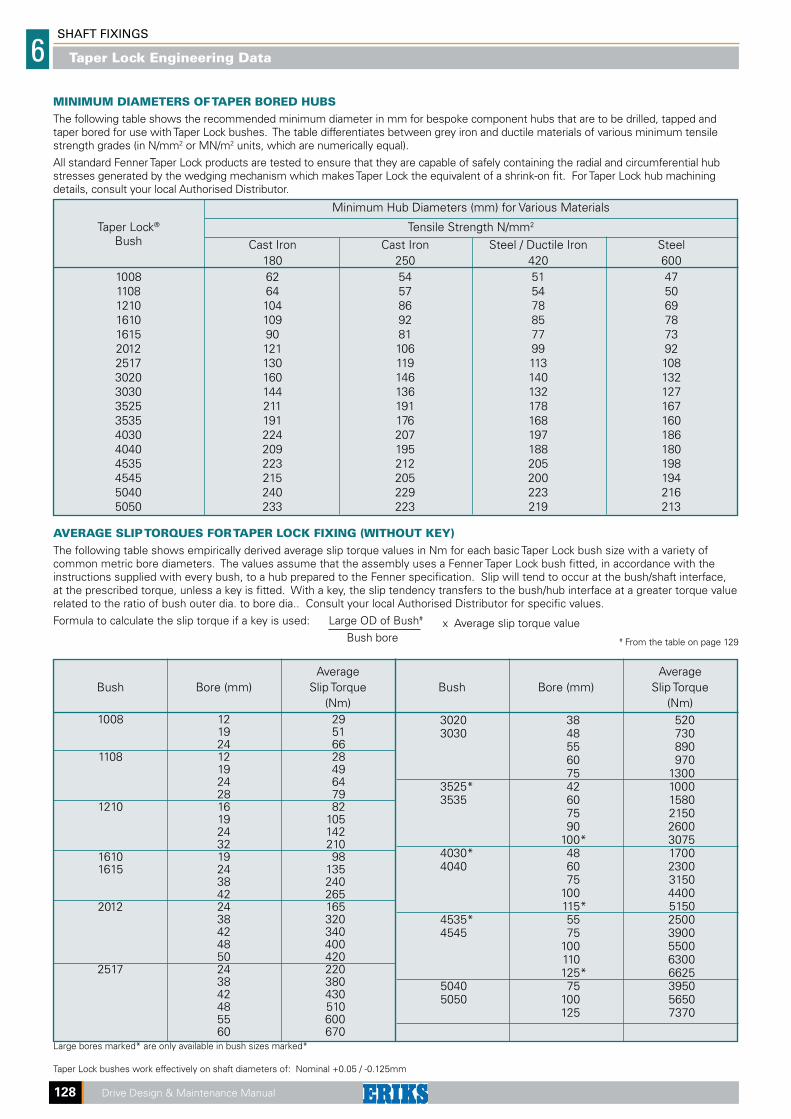
AVERAGE SLIP TORQUES FOR TAPER LOCK FIXING (WITHOUT KEY)The following table shows empirically derived average slip torque values in Nm for each basic Taper Lock bush size with a variety of common metric bore diameters. The values assume that the assembly uses a Fenner Taper Lock bush fitted, in accordance with the instructions supplied with every bush, to a hub prepared to the Fenner specification. Slip will tend to occur at the bush/shaft interface, at the prescribed torque, unless a key is fitted. With a key, the slip tendency transfers to the bush/hub interface at a greater torque value related to the ratio of bush outer dia. to bore dia.. Consult your local Authorised Distributor for specific values.
Formula to calculate the slip torque if a key is used: Large OD of Bush# x Average slip torque value Bush bore # From the table on page 129
Average Average Bush Bore (mm) Slip Torque Bush Bore (mm) Slip Torque (Nm) (Nm) 1008 12 29 19 51 24 66 1108 12 28 19 49 24 64 28 79 1210 16 82 19 105 24 142 32 210 1610 19 98 1615 24 135 38 240 42 265 2012 24 165 38 320 42 340 48 400 50 420 2517 24 220 38 380 42 430 48 510 55 600 60 670Large bores marked* are only available in bush sizes marked*
Taper Lock bushes work effectively on shaft diameters of: Nominal +0.05 / -0.125mm
3020 38 520 3030 48 730 55 890 60 970 75 1300 3525* 42 1000 3535 60 1580 75 2150 90 2600 100* 3075 4030* 48 1700 4040 60 2300 75 3150 100 4400 115* 5150 4535* 55 2500 4545 75 3900 100 5500 110 6300 125* 6625 5040 75 3950 5050 100 5650 125 7370
MINIMUM DIAMETERS OF TAPER BORED HUBSThe following table shows the recommended minimum diameter in mm for bespoke component hubs that are to be drilled, tapped and taper bored for use with Taper Lock bushes. The table differentiates between grey iron and ductile materials of various minimum tensile strength grades (in N/mm2 or MN/m2 units, which are numerically equal).
All standard Fenner Taper Lock products are tested to ensure that they are capable of safely containing the radial and circumferential hub stresses generated by the wedging mechanism which makes Taper Lock the equivalent of a shrink-on fit. For Taper Lock hub machining details, consult your local Authorised Distributor.
Minimum Hub Diameters (mm) for Various Materials
Taper Lock® Tensile Strength N/mm2
Bush Cast Iron Cast Iron Steel / Ductile Iron Steel 180 250 420 600 1008 62 54 51 47 1108 64 57 54 50 1210 104 86 78 69 1610 109 92 85 78 1615 90 81 77 73 2012 121 106 99 92 2517 130 119 113 108 3020 160 146 140 132 3030 144 136 132 127 3525 211 191 178 167 3535 191 176 168 160 4030 224 207 197 186 4040 209 195 188 180 4535 223 212 205 198 4545 215 205 200 194 5040 240 229 223 216 5050 233 223 219 213
Taper Lock Engineering Data

SH
AFT
FIX
ING
SS
ecti
on
SHAFT FIXINGS 6
Drive Design & Maintenance Manual 129
TO REMOVESlacken all screws by several turns, 1. remove one or two according to number of removal holes shown thus in diagram. Insert screws into removal holes after oiling thread and under head of cap screws.
TO INSTALLAfter ensuring that the mating 1. tapered surfaces, bore and shaft are completely clean and free from oil or dirt, insert bush in hub so that holes line up.
Sparingly oil thread and point of grub 2. screws, or thread and under head of cap screws. Place screws loosely in holes threaded in hub, shown thus in diagram.
If a key is to be fitted place it in the 3. shaft keyway before fitting the bush. It is essential that it is a parallel key and side fitting only and has TOP CLEARANCE.
Clean shaft and fit hub to shaft as one 4. unit and locate in position desired, remembering that bush will nip the shaft first and then hub will be slightly drawn on to the brush.
Using a hexagon wrench tighten 5. screws gradually and alternately to torque shown in table below.
Hammer against large-end of bush, 6. using a block or sleeve to prevent damage. (This will ensure that the bush is seated squarely in the bore.) Screws will now turn a little more. Repeat this alternate hammering and screw tightening once or twice to achieve maximum grip on the shaft.
After drive has been running under 7. load for a short time stop and check tightness of screws.
Fill empty holes with grease to 8. exclude dirt.
Tighten screws alternately until bush 2. is loosened in hub and assembly is free on the shaft.
Remove assembly from shaft.3.
Bush size 1008 1108 1210 1610 1615 2012 2517 3020 3030 3525 3535 4030 4040 4535 4545 5040 5050
Screw tighteningtorque (Nm) 5.6 5.6 20 20 20 30 50 90 90 115 115 170 170 190 190 270 270
qty 2 2 2 2 2 2 2 2 2 3 3 3 3 3 3 3 3
size Screw (BSW)
1/4" 1/4" 3/8" 3/8" 3/8" 7/16" 1/2" 5/8" 5/8" 1/2" 1/2" 5/8" 5/8" 3/4" 3/4" 7/8" 7/8"
details Hex. socket 3 3 5 5 5 6 6 8 8 10 10 12 12 14 14 14 14 size (mm)
Large end dia. (mm) 35.0 38.0 47.5 57.0 57.0 70.0 85.5 108.6 108 127 127 146 146 162 162 178 178
Bush length (mm) 22.3 22.3 25.4 25.4 38.1 31.8 44.5 50.8 76.2 63.5 89.0 76.2 102 89.0 114 102 127
Approx mass (kg) 0.1 0.1 0.2 0.3 0.5 0.7 1.5 2.7 3.6 3.8 5.0 5.6 7.7 7.5 10.0 11.1 14.0
REMOVAL HOLES
INSERT BUSH INSERT SCREWS AND
LOCATE ON SHAFT
TIGHTEN SCREWS FINGER
TIGHT
TIGHTEN SCREWS
ALTERNATELY
REMOVAL
Taper Lock Installtion Instructions
SHAFT FIXINGS
6
130 Drive Design & Maintenance Manual
THE PROBLEMFor many years, the power transmission industry has struggled with the problems of mounting components to shafts. The "industry standard", the keyed mounting, has a number of widely acknowledged limitations. The process of cutting keyways into the shaft is time-consuming, tedious and permanent. There's little chance to adjust timing or synchronise a drive, and cutting the keyway or slot reduces the strength of the shaft.
In addition, the stress of stopping, starting and transmitting power under high torque can induce fretting corrosion and cracking that can ultimately result in unit failure. Even the smallest discrepancies in the fit between the hub and the shaft will increase fretting corrosion and wear and cause premature failure of the mounting. Poor fit will also allow "backlash" during rapid stops.
It's not surprising, then, that many manufacturers have eliminated keyway problems and switched to TRANTORQUE GT.
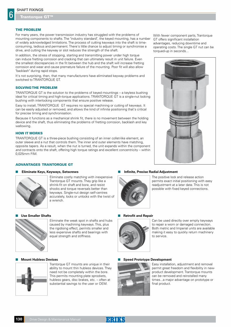
SOLVING THE PROBLEMTRANTORQUE GT is the solution to the problems of keyed mountings – a keyless bushing ideal for critical timing and high-torque applications. TRANTORQUE GT is a single-nut locking bushing with interlocking components that ensure positive release.
Easy to install, TRANTORQUE GT requires no special machining or cutting of keyways. It can be easily adjusted or removed, and allows the kind of infinite positioning that's critical for precise timing and synchronisation.
Because it functions as a mechanical shrink fit, there is no movement between the holding device and the shaft, thus eliminating the problems of fretting corrosion, backlash and key wallowing.
HOW IT WORKSTRANTORQUE GT is a three-piece bushing consisting of an inner collet-like element, an outer sleeve and a nut that controls them. The inner and outer elements have matching, opposite tapers. As a result, when the nut is turned, the unit expands within the component and contracts onto the shaft, offering high torque ratings and excellent concentricity – within 0,025mm FIM.
ADVANTAGES TRANTORQUE GT
Eliminate Keys, Keyways, Setscrews Infinite, Precise Radial Adjustment
Use Smaller Shafts Retrofit and Repair
Mount Hubless Devices Speed Prototype Development
Eliminate the weak spot in shafts and hubs caused by machining keyways. This, plus the rigidising effect, permits smaller and less expensive shafts and bearings with equal strength and stiffness.
Trantorque GT mounts are unique in their ability to mount thin hubless devices. They need not be completely within the bore. This permits mounting plate sprockets, hubless gears, disc brakes, etc. – often at substantial savings to the user or OEM.
The positive lock and release action permits exact initial positioning with easy readjustment at a later date. This is not possible with fixed keyed connections.
Eliminate costly matching with inexpensive Trantorque GT mounts. They grip like a shrink-fit on shaft and bore, and resist shocks and torque reversals better than keyways. Single-nut design self-centres accurately, locks or unlocks with the twist of a wrench.
Can be used directly over empty keyways to repair a worn or damaged connection. Both metric and Imperial units are available making it easy to quickly return machinery to service.
Easy installation, adjustment and removal permit great freedom and flexibility in new-product development. Trantorque mounts can be removed and reinstalled many times...a major advantage on prototype or final product.
With fewer component parts, Trantorque GT offers significant installation advantages, reducing downtime and operating costs. The single GT nut can be torqued-up in seconds...
Trantorque GT™

SH
AFT
FIX
ING
SS
ecti
on
SHAFT FIXINGS 6
Drive Design & Maintenance Manual 131
SELECTIONTo select the TRANTORQUE GT suitable for your application simply choose the bush with the appropriate ('d') to suit the shaft diameter and determine that the outside diameter ('D') and transmissible torque rating will be adequate.
Note: The nominal transmitted torque in Nm should be multiplied by a service factor be-fore comparing with the tabulated maximum transmissible torque.
Service factors range from 1.0 for electric motor driven, smooth machines, to 2.25 for heavy shock machinery driven by i/c engines.
If in doubt consult your local Authorised Distributor.
Use the following formula to convert power (kW) to torque (Nm) Torque (Nm) = kW x 9550 rev/min
INSTALLATION Clean off the shaft and bore with a clean rag dampened with a commercial solvent so that the bore and the shaft are clean and completely free of oil.
Fit the TRANTORQUE GT unit onto the shaft: the shaft must extend through the full length of the TRANTORQUE GT (dimension L1).
Fit the hub over the TRANTORQUE GT unit so that the expanding section of the unit (dimension L2) is approximately in the centre of the hub. If the hub is longer than the L2 dimension, make sure that the flats of the nut(s) (dimensions B) are outside of the hub to permit spanners to be applied to the nut(s).
Tighten the outboard nut lightly by hand. Position the unit and the hub in the desired location. Now tighten the outboard nut to the torque indicated in the charts. The hub is now locked to the shaft. With Trantorque GT the inboard nut is used to restrain the unit and the shaft during tightening.
EFFECT OF TEMPERATURETRANTORQUE GT units are not affected by temperature within wide limits (–34OC to 204OC) when the shaft and hub are made of steel. TRANTORQUE GT units are all steel. If the shaft and/or hub are made of different materials e.g. aluminum, straightforward engi-neering compensation should be made for the difference in expansion coefficients.In normal environments, where the seasonal ambient variation is less than 35OC, no com-pensation will generally be required, even with dissimilar metals.
MOUNTING OF HUBLESS MACHINE ELEMENTSHubless machine elements such as plate gears, plate disc brakes, plate cams and plate sprockets, can be successfully locked to the shaft by means of the TRANTORQUE GT, but some account should be taken of the increased hub pressure on these applications.
DIMENSIONS PERFORMANCE NUT
Max Transmissible Hub TORQUE
Approximate PRODUCT d D L1 L2 A1 A2 B1 B2 Torque Thrust Resource Mass CODES Nm kgf N/cm2 Nm kg
184A0604 1/4" 5/8" 3/4" 3/8" 1/2" – 1/8" – 17.0 358 3585 14.1 0.014
184B0606 3/8" 3/4" 7/8" 7/16" 5/8" – 1/8" – 28.0 418 2550 17.0 0.028
184C0608 1/2" 7/8" 1" 1/2" 3/4" – 3/16" – 39.5 445 1857 19.8 0.042
184D0610 5/8" 1" 11/8" 5/8" 7/8" – 3/16" – 50.0 453 1240 22.6 0.056 184E0610 5/8" 11/2" 11/2" 3/4" 11/4" 11/2" 5/16" 5/16" 198.0 1497 7586 136.0 0.230 184E0612 3/4" 11/2" 11/2" 3/4" 11/4" 11/2" 5/16" 5/16" 282.0 1996 7586 136.0 0.230
184F0614 7/8" 13/4" 17/8" 7/8" 11/2" 13/4" 7/16" 3/8" 316.0 2495 6480 170.0 0.310 184F0616 1" 13/4" 17/8" 7/8" 11/2" 13/4" 7/16" 3/8" 395.0 2994 6480 170.0 0.310
184G0620 11/4" 2" 21/4" 1" 13/4" 2" 1/2" 9/16" 678.0 3856 5380 225.0 0.450
184H0624 11/2" 23/8" 23/4" 11/2" 2" 23/8" 9/16" 1/2" 790.0 4770 4480 260.0 0.770
184J0628 13/4" 25/8" 31/8" 111/16" 21/4" 25/8" 9/16" 11/16" 1130.0 5785 3790 315.0 1.050
184K0632 2" 27/8" 39/16" 2" 21/2" 27/8" 5/8" 3/4" 1582.0 6805 2900 550.0 1.360
184L0636 21/4" 31/8" 33/4" 21/8" 23/4" 31/8" 5/8" 13/16" 1695.0 6930 2415 600.0 2.130
184M0638 23/8" 33/8" 37/8" 21/4" 3" 33/8" 11/16" 3/4" 1750.0 6985 1930 635.0 2.270 184M0640 21/2" 33/8" 37/8" 21/4" 3" 33/8" 11/16" 3/4" 1810.0 7060 1930 635.0 2.270
184N0644 23/4" 35/8" 41/16" 23/8" 31/4" 35/8" 11/16" 13/16" 1920.0 7170 1655 680.0 2.530
184P0648 3" 37/8" 41/4" 21/2" 31/2" 37/8" 3/4" 13/16" 2030.0 7330 1585 750.0 2.720
Tolerances on shaft and bore, miniature Series ± .038 mm, (.0015"). Standard and Larger Series ± .076 mm, (0.03").Other sizes, types and materials are available to order. Consult your local Authorised Distributor.
MIN
IATU
RE
SER
IES
TRA
NTO
RQ
UE
STA
ND
AR
D S
ERIE
STR
AN
TOR
QU
E G
TLA
RGE
SER
IES
TRA
NTO
RQ
UE
GT
INCH STOCK RANGE
DIMENSIONS PERFORMANCE NUT
Max Transmissible Hub TORQUE
Approximate PRODUCT d D L1 L2 A1 A2 B1 B2 Torque Thrust Pressure Mass CODES Nm kgf N/cm2 Nm kg
184A0105 5 16.0 19.0 9.5 13 – 3.0 – 12 323 3585 14 0.014 184A0106 6 16.0 19.0 9.5 13 – 3.0 – 16 349 3585 14 0.014
184B0108 8 19.0 22.0 11.0 16 – 3.0 – 23 405 2550 17 0.028 184B0109 9 19.0 22.0 11.0 16 – 3.0 – 26 414 2550 17 0.028
184C0110 10 22.5 25.5 12.5 19 – 5.0 – 30 423 1860 20 0.042 184C0111 11 22.5 25.5 12.5 19 – 5.0 – 34 430 1860 20 0.042 184C0112 12 22.5 25.5 12.5 19 – 5.0 – 39 439 1860 20 0.042
184D0114 14 25.5 28.5 16.0 22 – 5.0 – 44 449 1240 23 0.056 184D0115 15 25.5 28.5 16.0 22 – 5.0 – 45 451 1240 23 0.056 184D0116 16 25.5 28.5 16.0 22 – 5.0 – 50 459 1240 23 0.056
184E0115 15 38.0 38.0 19.0 32 38.0 8.0 8.0 180 1366 7600 136 0.230 184E0116 16 38.0 38.0 19.0 32 38.0 8.0 8.0 198 1500 7600 136 0.230 184E0118 18 38.0 38.0 19.0 32 38.0 8.0 8.0 265 1835 7600 136 0.230 184E0119 19 38.0 38.0 19.0 32 38.0 8.0 8.0 282 2000 7600 136 0.230
184F0120 20 45.0 47.5 21.5 38 44.5 11.0 9.5 290 2140 6500 170 0.310 184F0122 22 45.0 47.5 21.5 38 44.5 11.0 9.5 315 2446 6500 170 0.310 184F0124 24 45.0 47.5 21.5 38 44.5 11.0 9.5 380 2752 6500 170 0.310 184F0125 25 45.0 47.5 21.5 38 44.5 11.0 9.5 390 2956 6500 170 0.310
184G0128 28 51.0 57.0 25.5 46 51.0 13.0 14.5 495 3262 5400 225 0.450 184G0130 30 51.0 57.0 25.5 46 51.0 13.0 14.5 580 3568 5400 225 0.450 184G0132 32 51.0 57.0 25.5 46 51.0 13.0 14.5 680 3874 5400 225 0.450
184H0134 34 60.5 70.0 38.0 50 60.3 14.0 13.0 710 4077 4500 260 0.770 184H0135 35 60.5 70.0 38.0 50 60.3 14.0 13.0 725 4281 4500 260 0.770 184H0136 36 60.5 70.0 38.0 50 60.3 14.0 13.0 750 4485 4500 260 0.770 184H0138 38 60.5 70.0 38.0 50 60.3 14.0 13.0 790 4791 4500 260 0.770
184J0140 40 67.0 79.5 43.0 60 67.0 14.5 17.5 900 5097 3800 315 1.050 184J0142 42 67.0 79.5 43.0 60 67.0 14.5 17.5 1000 5043 3800 315 1.050
184K0145 45 73.0 90.5 51.0 65 73.0 16.0 19.0 1170 5912 2900 550 1.360 184K0148 48 73.0 90.5 51.0 65 73.0 16.0 19.0 1356 6422 2900 550 1.360 184K0150 50 73.0 90.5 51.0 65 73.0 16.0 19.0 1515 6728 2900 550 1.360
184L0155 55 80.0 95.0 54.0 70 79.4 16.0 20.5 1650 6932 2400 600 2.130
184M0160 60 86.0 98.5 57.0 75 85.7 17.5 19.0 1745 7034 2000 635 2.270
184N0165 65 92.0 103.0 60.5 82 92.0 17.5 20.5 1830 7136 1700 680 2.680 184N0170 70 92.0 103.0 60.5 82 92.0 17.5 20.5 1920 7238 1700 680 2.680
184P0175 75 100.0 108.0 63.5 90 98.5 19.0 20.5 2000 7339 1600 750 2.720 LAR
GE
SER
IES
TRA
NTO
RQ
UE
GT
STA
ND
AR
D S
ERIE
S TR
AN
TOR
QU
E G
TM
INIA
TUR
E SE
RIE
STR
AN
TOR
QU
E
METRIC STOCK RANGE
Trantorque
Mini SeriesTrantorque GT
Trantorque GT™
SHAFT FIXINGS
6
132 Drive Design & Maintenance Manual
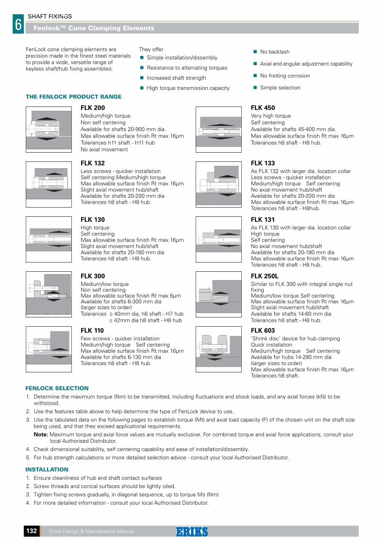
THE FENLOCK PRODUCT RANGE
FLK 200 FLK 450
Medium/high torque Very high torque Non self centering Self centering Available for shafts 20-900 mm dia. Available for shafts 45-400 mm dia. Max allowable surface finish Rt max 16μm Max allowable surface finish Rt max 16μm Tolerances h11 shaft - H11 hub Tolerances h8 shaft - H8 hub. No axial movement
FLK 132 FLK 133
Less screws - quicker installation As FLK 132 with larger dia. location collar Self centering Medium/high torque Less screws - quicker installation Max allowable surface finish Rt max 16μm Medium/high torque Self centering Slight axial movement hub/shaft No axial movement hub/shaft Available for shafts 20-200 mm dia Available for shafts 20-200 mm dia Tolerances h8 shaft - H8 hub. Max allowable surface finish Rt max 16μm Tolerances h8 shaft - H8hub.
FLK 130 FLK 131
High torque As FLK 130 with larger dia. location collar Self centering High torque Max allowable surface finish Rt max 16μm Self centering Slight axial movement hub/shaft No axial movement hub/shaft Available for shafts 20-180 mm dia Available for shafts 20-180 mm dia Tolerances h8 shaft - H8 hub. Max allowable surface finish Rt max 16μm Tolerances h8 shaft - H8 hub.
FLK 300 FLK 250L
Medium/low torque Similar to FLK 300 with integral single nut Non self centering fixing Max allowable surface finish Rt max 6μm Medium/low torque Self centering Available for shafts 6-300 mm dia Max allowable surface finish Rt max 16μm (larger sizes to order) Slight axial movement hub/shaft Tolerances ≥ 40mm dia, h6 shaft - H7 hub Available for shafts 14-60 mm dia ≤ 42mm dia h8 shaft - H8 hub Tolerances h8 shaft - H8 hub.
FLK 110 FLK 603
Few screws - quicker installation ‘Shrink disc’ device for hub clamping Medium/high torque Self centering Quick installation Max allowable surface finish Rt max 16μm Medium/high torque Self centering Available for shafts 6-130 mm dia Available for hubs 14-280 mm dia Tolerances h8 shaft - H8 hub. (larger sizes to order) Max allowable surface finish Rt max 16μm Tolerances h8 shaft.
FenLock cone clamping elements are precision made in the finest steel materials to provide a wide, versatile range of keyless shaft/hub fixing assemblies.
FENLOCK SELECTIONDetermine the maximum torque (Nm) to be transmitted, including fluctuations and shock loads, and any axial forces (kN) to be 1. withstood.
Use the features table above to help determine the type of FenLock device to use.2.
Use the tabulated data on the following pages to establish torque (Mt) and axial load capacity (F) of the chosen unit on the shaft size 3. being used, and that they exceed applicational requirements.
Note: Maximum torque and axial force values are mutually exclusive. For combined torque and axial force applications, consult your local Authorised Distributor.
Check dimensional suitability, self centering capability and ease of installation/dissembly.4.
For hub strength calculations or more detailed selection advice - consult your local Authorised Distributor.5.
INSTALLATIONEnsure cleanliness of hub and shaft contact surfaces1.
Screw threads and conical surfaces should be lightly oiled.2.
Tighten fixing screws gradually, in diagonal sequence, up to torque Ms (Nm)3.
For more detailed information - consult your local Authorised Distributor.4.
They offer
Simple installation/dissembly
Resistance to alternating torques
Increased shaft strength
High torque transmission capacity
No backlash
Axial and angular adjustment capability
No fretting corrosion
Simple selection
Fenlock™ Cone Clamping Elements
SH
AFT
FIX
ING
SS
ecti
on
SHAFT FIXINGS 6
Drive Design & Maintenance Manual 133
COEFFICIENT KFACTOR C
Type 1 C = 1.0
Narrow hubs where the length ≥ L1
Type 2 C = 0.8
Wide hubs with centre guide and length ≥ 2L1
ASSEMBLIES TYPE
To Calculate the Minimum Hub Diameter (Dm).FenLock cone clamping elements create a surface pressure Pn between the clamping outer ring and hub bore when fitted. Shaft values are higher than the hub stresses but generally the hub stress level is the critical factor as it must be below the yield stress of the material.
The minimum hub diameter Dm is calculated using the following formula
Dm ≥ (D.K)
where
Dm = Minimum hub diameter
D = Outside diameter of clamping element
K = Coefficient K derived from the table below
Use Pn from product tables on pages 134 - 138
factor C (see below)
Example
Based on securing a cast iron 50mm wide pulley to a steel shaft using a FenLock 200 80 x 120.Pulley Material = GG25
C = 0.8 as assembly is as per type 2
Pn = 120 N/mm2 as page 134
K = 1,81
Dm ≥ (D.K)
Dm ≥ (120 x 1.81)
Dm ≥ 217.2mm
Therefore, the minimum hub diameter that can be used is 217.2mm.
Pressure generated Yeild point N/mm2 on the hub 150 180 200 220 250 270 300 350 400 450 600 Material type
Pn Applica- GG20 GG25 GG30 GS45 GGG40 ST50-2 GGG50 GGG60 GGG70 N/mm2 tion type GS38 GTS35 ST37-2 GS52 C35 GS60 GS62 GS70 C ST60-2 ST70-2 C60
60 C=0.6 1.28 1.25 1.20 1.18 1.15 1.14 1.12 1.10 1.09 1.08 1.06 C=0.8 1.39 1.30 1.24 1.23 1.22 1.20 1.18 1.15 1.12 1.11 1.08 C= 1 1.52 1.42 1.36 1.32 1.28 1.25 1.22 1.18 1.16 1.14 1.10
65 C=0.6 1.30 1.25 1.22 1.20 1.18 1.15 1.13 1.11 1.10 1.09 1.07 C=0.8 1.44 1.35 1.30 1.28 1.24 1.22 1.20 1.16 1.14 1.12 1.09 C= 1 1.60 1.45 1.40 1.35 1.30 1.28 1.24 1.20 1.18 1.16 1.12
70 C=0.6 1.34 1.26 1.24 1.22 1.18 1.16 1.15 1.12 1.11 1.10 1.07 C=0.8 1.48 1.38 1.34 1.30 1.25 1.23 1.20 1.18 1.15 1.13 1.10 C= 1 1.65 1.50 1.45 1.40 1.34 1.30 1.26 1.22 1.20 1.17 1.13
75 C=0.6 1.30 1.28 1.25 1.23 1.20 1.18 1.16 1.14 1.12 1.11 1.08 C=0.8 1.52 1.42 1.36 1.32 1.28 1.25 1.22 1.18 1.16 1.14 1.11 C= 1 1.74 1.55 1.48 1.42 1.36 1.33 1.30 1.25 1.20 1.18 1.13
80 C=0.6 1.39 1.31 1.28 1.25 1.21 1.20 1.18 1.15 1.13 1.11 1.08 C=0.8 1.58 1.45 1.39 1.35 1.30 1.27 1.24 1.20 1.18 1.15 1.11 C= 1 1.81 1.61 1.53 1.46 1.39 1.36 1.31 1.26 1.22 1.20 1.14
85 C=0.6 1.42 1.34 1.30 1.27 1.23 1.21 1.19 1.16 1.14 1.12 1.09 C=0.8 1.63 1.49 1.42 1.38 1.32 1.29 1.26 1.22 1.19 1.16 1.12 C= 1 1.90 1.67 1.57 1.50 1.42 1.39 1.34 1.28 1.24 1.21 1.15
90 C=0.6 1.46 1.36 1.32 1.28 1.25 1.22 1.20 1.17 1.15 1.13 1.09 C=0.8 1.69 1.53 1.46 1.40 1.34 1.31 1.28 1.23 1.20 1.18 1.13 C= 1 2.00 1.73 1.62 1.54 1.46 1.41 1.36 1.30 1.26 1.22 1.16
95 C=0.6 1.49 1.39 1.34 1.30 1.26 1.24 1.21 1.18 1.15 1.14 1.10 C=0.8 1.75 1.57 1.49 1.43 1.37 1.34 1.30 1.25 1.21 1.19 1.14 C= 1 2.11 1.80 1.68 1.59 1.49 1.44 1.39 1.32 1.27 1.24 1.17
100 C=0.6 1.53 1.41 1.36 1.32 1.28 1.25 1.22 1.19 1.16 1.14 1.11 C=0.8 1.81 1.61 1.53 1.46 1.39 1.36 1.31 1.26 1.22 1.20 1.14 C= 1 2.24 1.87 1.73 1.63 1.53 1.48 1.41 1.34 1.29 1.25 1.18
105 C=0.6 1.56 1.44 1.39 1.34 1.29 1.27 1.24 1.20 1.17 1.15 1.11 C=0.8 1.88 1.66 1.56 1.50 1.42 1.38 1.33 1.28 1.24 1.21 1.15 C= 1 2.38 1.95 1.79 1.68 1.56 1.51 1.44 1.36 1.31 1.27 1.19
110 C=0.6 1.60 1.47 1.41 1.36 1.31 1.28 1.25 1.21 1.18 1.16 1.12 C=0.8 1.96 1.71 1.60 1.53 1.44 1.41 1.35 1.29 1.25 1.22 1.16 C= 1 2.55 2.04 1.86 1.73 1.60 1.54 1.47 1.38 1.33 1.28 1.20
115 C=0.6 1.64 1.50 1.43 1.36 1.33 1.30 1.26 1.22 1.19 1.17 1.12 C=0.8 2.04 1.76 1.64 1.56 1.47 1.43 1.37 1.31 1.26 1.23 1.17 C= 1 2.75 2.13 1.93 1.79 1.64 1.58 1.50 1.41 1.34 1.30 1.21
120 C=0.6 1.69 1.53 1.46 1.40 1.34 1.31 1.28 1.23 1.20 1.18 1.13 C=0.8 2.13 1.81 1.69 1.60 1.50 1.45 1.39 1.33 1.28 1.24 1.18 C= 1 3.00 2.24 2.00 1.84 1.69 1.61 1.53 1.43 1.36 1.31 1.22
125 C=0.6 1.73 1.56 1.48 1.43 1.36 1.33 1.29 1.24 1.21 1.18 1.13 C=0.8 2.24 1.87 1.73 1.63 1.53 1.48 1.41 1.34 1.29 1.25 1.18 C= 1 3.32 2.35 2.08 1.91 1.73 1.65 1.56 1.45 1.38. 1.33 1 24
130 C=0.6 1.78 1.59 1.51 1.45 1.38 1.35 1.30 1.25 1.22 1.19 1.14 C=0.8 2.35 1.93 1.78 1.67 1.56 1.50 1.44 1.36 1.30 1.27 1.19 C= 1 3.74 2.49 2.17 1.97 1.78 1.69 1.59 1.48 1.40 1.35 1.25
135 C=0.6 1.83 1.62 1.54 1.47 1.40 1.36 1.32 1.27 1.23 1.20 1.15 C=0.8 2.48 2.00 1.83 1.71 1.59 1.53 1.46 1.38 1.32 1.28 1.20 C= 1 4.36 2.65 2.27 2.04 1.83 1.73 1.62 1.50 1.42 1.36 1.26
140 C=0.6 1.88 1.66 1.56 1.50 1.42 1.38 1.33 1.28 1.24 1.21 1.15 C=0.8 2.63 2.07 1.88 1.75 1.62 1.55 1.48 1.39 1.33 1.29 1.21 C= 1 5.39 2.83 2.38 2.12 1.88 1.78 1.66 1.53 1.44 1.38 1.27
145 C=0.6 1.94 1.69 1.59 1.52 1.44 1.40 1.35 1.29 1.25 1.22 1.16 C=0.8 2.80 2.15 1.94 1.80 1.65 1.58 1.50 1.41 1.35 1.30 1.22 C= 1 7.68 3.05 2.50 2.21 1.94 1.82 1.69 1.55 1.46 1.40 1.28
150 C=0.6 2.00 1.73 1.62 1.54 1.46 1.41 1.36 1.30 1.26 1.23 1.16 C=0.8 3.00 2.24 2.00 1.84 1.69 1.61 1.53 1.43 1.36 1.31 1.23 C= 1 —— 3.32 2.65 2.30 2.00 1.87 1.73 1.58 1.48 1.41 1.29
155 C=0.6 2.06 1.77 1.65 1.57 1.48 1.43 1.38 1.31 1.27 1.24 1.17 C=0.8 3.25 2.33 2.06 1.89 1.72 1.65 1.55 1.45 1.38 1.33 1.23 C= 1 —— 3.66 2.80 2.40 2.06 1.92 1.77 1.61 1.51 1.43 1.30
160 C=0.6 2.13 1.81 1.69 1.60 1.50 1.45 1.39 1.33 1.28 1.24 1.18 C=0.8 3.55 2.43 2.13 1.94 1.76 1.67 1.58 1.47 1.39 1.34 1.24 C= 1 —— 4.12 3.00 2.52 2.13 1.98 1.81 1.64 1.53 1.45 1.31
165 C=0.6 2.21 1.86 1.72 1.62 1.52 1.47 1.41 1.34 1.29 1.25 1.18 C=0.8 3.96 2.55 2.21 2.00 1.80 1.71 1.60 1.49 1.41 1.35 1.25 C= 1 —— 4.80 3.23 2.65 2.21 2.04 1.86 1.67 1.55 1.47 1.33
Fenlock™ Cone Clamping Elements
Type 3 C = 0.6
Wide hubs where the length ≥ 2L1
SHAFT FIXINGS
6
134 Drive Design & Maintenance Manual
Tightening screws Torque Axial Hub Tightening Product Thrust Stress Grade Torque Code d x D L1 L2 B Mt F ass. Pn 12.9 Ms mm mm mm mm Nm kN N/mm2 No. x type Nm 630A0020 20 x 47 17 20 27.5 280 29 95 8 x M6 15 630A0022 22 x 47 17 20 27.5 310 29 95 8 x M6 15 630A0024 24 x 50 17 20 27.5 370 32 100 8 x M6 15 630A0025 25 x 50 17 20 27.5 400 32 100 8 x M6 15 630A0028 28 x 55 17 20 27.5 500 36 100 10 x M6 15 630A0030 30 x 55 17 20 27.5 530 36 100 10 x M6 15 630A0032 32 x 60 17 20 27.5 680 42 110 12 x M6 15 630A0035 35 x 60 17 20 27.5 750 43 110 12 x M6 15 630A0038 38 x 65 17 20 27.5 930 49 115 14 x M6 15 630A0040 40 x 65 17 20 27.5 980 49 115 14 x M6 15 630A0042 42 x 75 20 24 33.5 1580 75 130 12 x M8 37 630A0045 45 x 75 20 24 33.5 1700 76 130 12 x M8 37 630A0048 48 x 80 20 24 33.5 1790 74 120 12 x M8 37 630A0050 50 x 80 20 24 33.5 1870 75 120 12 x M8 37 630A0055 55 x 85 20 24 33.5 2390 88 135 14 x M8 37 630A0060 60 x 90 20 24 33.5 2610 88 125 14 x M8 37 630A0065 65 x 95 20 24 33.5 3210 98 135 16 x M8 37 630A0070 70 x 110 24 28 39.5 4600 132 130 14 x M10 70 630A0075 75 x 115 24 28 39.5 4900 131 125 14 x M10 70 630A0080 80 x 120 24 28 39.5 5200 131 120 14 x M10 70 630A0085 85 x 125 24 28 39.5 6300 148 130 15 x M10 70 630A0090 90 x 130 24 28 39.5 6600 147 125 16 x M10 70 630A0095 95 x 135 24 28 39.5 7900 167 135 18 x M10 70 630A0100 100 x 145 26 33 47.0 9750 195 135 14 x M12 127 630A0110 110 x 155 26 33 47.0 10650 194 125 14 x M12 127 630A0120 120 x 165 26 33 47.0 13300 221 135 16 x M12 127 630A0130 130 x 180 34 38 52.0 17850 276 115 20 x M12 127 630A0140 140 x 190 34 38 52.0 21200 302 125 22 x M12 127 630A0150 150 x 200 34 38 52.0 24500 329 125 24 x M12 127 630A0160 160 x 210 34 38 52.0 28400 355 130 26 x M12 127 630A0170 170 x 225 38 44 60.0 33600 396 120 22 x M14 195 630A0180 180 x 235 38 44 60.0 38700 431 130 24 x M14 195 630A0190 190 x 250 46 52 68.0 44700 502 120 28 x M14 195 630A0200 200 x 260 46 52 68.0 53500 538 120 30 x M14 195 630A0220 220 x 285 50 56 74.0 68500 630 120 26 x M16 300 630A0240 240 x 305 50 56 74.0 86000 717 130 30 x M16 300 630A0260 260 x 325 50 56 74.0 105000 810 135 34 x M16 300 630A0280 280 x 355 60 66 86.5 128500 920 120 32 x M18 410 630A0300 300 x 375 60 66 86.5 153600 1025 125 36 x M18 410 630A0320 320 x 405 72 78 100.5 210500 1325 125 36 x M20 590 630A0340 340 x 425 72 78 100.5 225000 1325 120 36 x M20 590 630A0360 360 x 455 84 90 116.0 294700 1635 120 36 x M22 790 630A0380 380 x 475 84 90 116.0 309100 1625 120 36 x M22 790 630A0400 400 x 495 84 90 116.0 321900 1617 110 36 x M22 790 630A0420 420 x 515 84 90 116.0 374000 1780 110 40 x M22 790 630A0440 440 x 545 96 102 130.0 455000 2060 105 40 x M24 1000 630A0460 460 x 565 96 102 130.0 470000 2040 100 40 x M24 1000 630A0480 480 x 585 96 102 130.0 515000 2160 100 42 x M24 1000 630A0500 500 x 605 96 102 130.0 560000 2240 100 44 x M24 1000 630A0520 520 x 630 96 102 130.0 600000 2320 100 45 x M24 1000 630A0540 540 x 650 96 102 130.0 630000 2340 100 45 x M24 1000 630A0560 560 x 670 96 102 130.0 680000 2440 100 48 x M24 1000 630A0580 580 x 690 96 102 130.0 735000 2540 100 50 x M24 1000 630A0600 600 x 710 96 102 130.0 775000 2580 100 50 x M24 1000 630A0620 620 x 730 96 102 130.0 825000 2660 100 52 x M24 1000 630A0640 640 x 750 96 102 130.0 865000 2700 100 54 x M24 1000 630A0660 660 x 770 96 102 130.0 925000 2800 100 56 x M24 1000 630A0680 680 x 790 96 102 130.0 965000 2840 100 56 x M24 1000 630A0700 700 x 810 96 102 130.0 1030000 2960 100 60 x M24 1000 630A0720 720 x 830 96 102 130.0 1070000 2980 100 60 x M24 1000 630A0740 740 x 850 96 102 130.0 1140000 3080 100 62 x M24 1000 630A0760 760 x 870 96 102 130.0 1210000 3180 100 64 x M24 1000 630A0780 780 x 890 96 102 130.0 1250000 3220 100 65 x M24 1000 630A0800 800 x 910 96 102 130.0 1300000 3260 100 66 x M24 1000 630A0820 820 x 930 96 102 130.0 1370000 3340 100 68 x M24 1000 630A0840 840 x 950 96 102 130.0 1450000 3460 100 70 x M24 1000 630A0860 860 x 970 96 102 130.0 1520000 3540 100 72 x M24 1000 630A0880 880 x 990 96 102 130.0 1590000 3620 100 74 x M24 1000 630A0900 900 x 1010 96 102 130.0 1650000 3680 100 75 x M24 1000
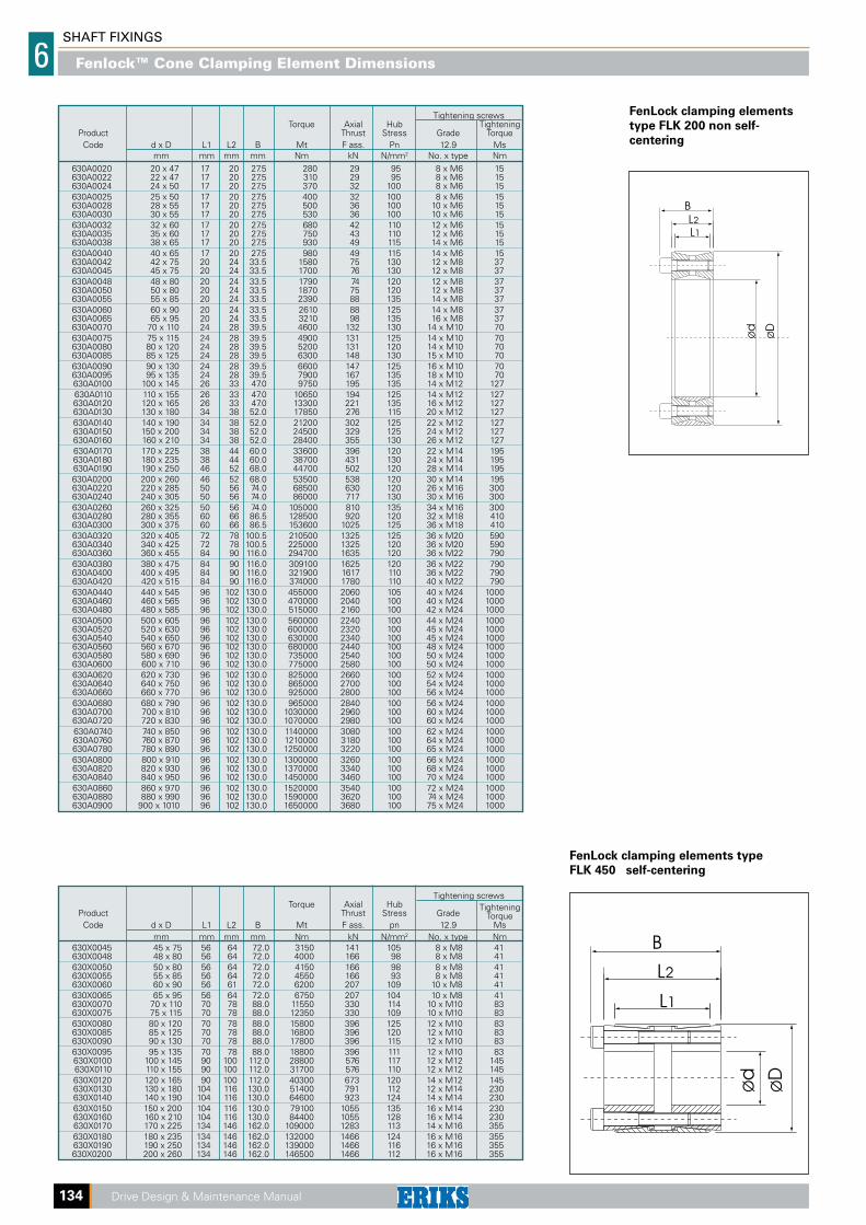
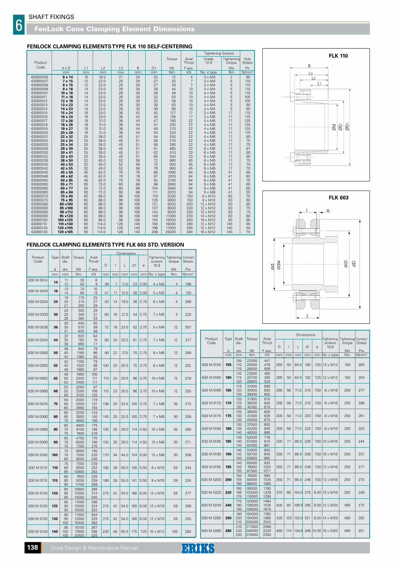
FenLock clamping elements
type FLK 200 non self-
centering
FenLock clamping elements type
FLK 450 self-centering
Tightening screws Torque Axial Hub Tightening Product Thrust Stress Grade Torque Code d x D L1 L2 B Mt F ass. pn 12.9 Ms mm mm mm mm Nm kN N/mm2 No. x type Nm 630X0045 45 x 75 56 64 72.0 3150 141 105 8 x M8 41 630X0048 48 x 80 56 64 72.0 4000 166 98 8 x M8 41 630X0050 50 x 80 56 64 72.0 4150 166 98 8 x M8 41 630X0055 55 x 85 56 64 72.0 4550 166 93 8 x M8 41 630X0060 60 x 90 56 61 72.0 6200 207 109 10 x M8 41 630X0065 65 x 95 56 64 72.0 6750 207 104 10 x M8 41 630X0070 70 x 110 70 78 88.0 11550 330 114 10 x M10 83 630X0075 75 x 115 70 78 88.0 12350 330 109 10 x M10 83 630X0080 80 x 120 70 78 88.0 15800 396 125 12 x M10 83 630X0085 85 x 125 70 78 88.0 16800 396 120 12 x M10 83 630X0090 90 x 130 70 78 88.0 17800 396 115 12 x M10 83 630X0095 95 x 135 70 78 88.0 18800 396 111 12 x M10 83 630X0100 100 x 145 90 100 112.0 28800 576 117 12 x M12 145 630X0110 110 x 155 90 100 112.0 31700 576 110 12 x M12 145 630X0120 120 x 165 90 100 112.0 40300 673 120 14 x M12 145 630X0130 130 x 180 104 116 130.0 51400 791 112 12 x M14 230 630X0140 140 x 190 104 116 130.0 64600 923 124 14 x M14 230 630X0150 150 x 200 104 116 130.0 79100 1055 135 16 x M14 230 630X0160 160 x 210 104 116 130.0 84400 1055 128 16 x M14 230 630X0170 170 x 225 134 146 162.0 109000 1283 113 14 x M16 355 630X0180 180 x 235 134 146 162.0 132000 1466 124 16 x M16 355 630X0190 190 x 250 134 146 162.0 139000 1466 116 16 x M16 355 630X0200 200 x 260 134 146 162.0 146500 1466 112 16 x M16 355
Fenlock™ Cone Clamping Element Dimensions
SH
AFT
FIX
ING
SS
ecti
on
SHAFT FIXINGS 6
Drive Design & Maintenance Manual 135
FLK Tightening Screws 133 Grade Tightening torque Torque Axial Hub Torque Axial Hub Product Only 12.9 Ms Thrust Stress Thrust Stress
Code d x D L1 L2 L3 B D1 Nm Mt F ass. Pn Mt F ass. Pn
mm mm mm mm mm mm No. x type FLK 132 FLK 133 Nm kN N/mm2 Nm kN N/mm2
630 R/G 0020 20 x 47 17 22 28 34 54 5 x M6 14 17 380 38 125 280 28 95 630 R/G 0022 22 x 47 17 22 28 34 54 5 x M6 14 17 410 38 125 300 28 95 630 R/G 0024 24 x 50 17 22 28 34 57 5 x M6 14 17 450 38 120 330 28 90 630 R/G 0025 25 x 50 17 22 28 34 57 6 x M6 14 17 570 46 140 420 34 105 630 R/G 0028 28 x 55 17 22 28 34 62 6 x M6 14 17 630 46 130 470 34 95 630 R/G 0030 30 x 55 17 22 28 34 62 6 x M6 14 17 660 46 130 500 34 95 630 R/G 0032 32 x 60 17 22 28 34 67 8 x M6 14 17 970 60 155 720 45 115 630 R/G 0035 35 x 60 17 22 28 34 67 8 x M6 14 17 1060 60 155 790 45 115 630 R/G 0038 38 x 65 17 22 28 34 72 8 x M6 14 17 1150 60 145 850 45 105 630 R/G 0040 40 x 65 17 22 28 34 72 8 x M6 14 17 1210 60 145 900 45 105 630 R/G 0042 42 x 75 20 25 33 41 82 7 x M8 35 41 2050 98 170 1530 73 125 630 R/G 0045 45 x 75 20 25 33 41 82 7 x M8 35 41 2200 98 170 1650 73 125 630 R/G 0048 48 x 80 20 25 33 41 87 7 x M8 35 41 2350 98 160 1760 73 120 630 R/G 0050 50 x 80 20 25 33 41 87 7 x M8 35 41 2450 98 160 1830 73 120 630 R/G 0055 55 x 85 20 25 33 41 92 8 x M8 35 41 3080 112 175 2300 83 130 630 R/G 0060 60 x 90 20 25 33 41 97 8 x M8 35 41 3360 112 165 2510 83 125 630 R/G 0065 65 x 95 20 25 33 41 102 9 x M8 35 41 4090 126 175 3060 94 130 630 R/G 0070 70 x 110 24 30 40 50 117 8 x M10 70 83 6300 179 180 4670 133 135 630 R/G 0075 75 x 115 24 30 40 50 122 8 x M10 70 83 6700 179 170 5000 133 125 630 R/G 0080 80 x 120 24 30 40 50 127 8 x M10 70 83 7150 179 170 5300 133 125 630 R/G 0085 85 x 125 24 30 40 50 132 9 x M10 70 83 8500 200 180 6300 148 135 630 R/G 0090 90 x 130 24 30 40 50 137 9 x M10 70 83 9100 200 170 6750 148 130 630 R/G 0095 95 x 135 24 30 40 50 142 10 x M10 70 83 10600 224 180 7900 166 135 630 R/G 0100 100 x 145 26 32 44 56 152 8 x M12 125 145 13400 268 190 9700 194 140 630 R/G 0110 110 x 155 26 32 44 56 162 8 x M12 125 145 14600 268 180 10600 194 130 630 R/G 0120 120 x 165 26 32 44 56 172 9 x M12 125 145 17900 298 180 13000 216 135 630 R/G 0130 130 x 180 34 40 54 66 187 12 x M12 125 145 26000 400 170 18900 290 125 630 R/G 0140 140 x 190 34 40 54 68 197 9 x M14 190 230 27000 384 150 20500 290 120 630 R/G 0150 150 x 200 34 40 54 68 207 10 x M14 190 230 33000 440 170 25000 333 130 630 R/G 0160 160 x 210 34 40 54 68 217 11 x M14 190 230 38000 479 170 29000 362 135 630 R/G 0170 170 x 225 44 50 64 78 232 12 x M14 190 230 45000 530 130 34000 400 105 630 R/G 0180 180 x 235 44 50 64 78 242 12 x M14 190 230 47000 530 130 36000 400 105 630 R/G 0190 190 x 250 44 50 64 78 257 15 x M14 190 230 62900 660 150 47500 500 120 630 R/G 0200 200 x 260 44 50 64 78 267 15 x M14 190 230 66000 660 150 50000 500 115
R = FLK 132 G = FLK 133NOTE: It is possible to reduce the screw tightening torque down to 60% of the values indicated in above table; as a result Mt & F ass, are reduced proportionally.
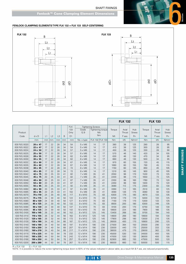
FENLOCK CLAMPING ELEMENTS TYPE FLK 132 + FLK 133 SELF-CENTERING
FLK 132 FLK 133
FLK 132 FLK 133
Fenlock™ Cone Clamping Element Dimensions
SHAFT FIXINGS
6
136 Drive Design & Maintenance Manual
FLK Tightening Screws 131 Grade Tightening Torque Axial Hub Torque Axial Hub Product Only 12.9 torque Thrust Stress Thrust Stress
Code d x D L1 L2 L3 B D1 Ms Mt F ass. Pn Mt F ass. Pn
mm mm mm mm mm mm No. x type Nm Nm kN N/mm2 Nm kN N/mm2
630 C/D 0020 20 x 47 26 30 41 47 53 6 x M6 17 540 54 120 330 34 75 630 C/D 0022 22 x 47 26 30 41 47 53 6 x M6 17 600 54 120 370 34 75 630 C/D 0024 24 x 50 26 30 41 47 56 6 x M6 17 650 54 115 400 34 70 630 C/D 0025 25 x 50 26 30 41 47 56 6 x M6 17 680 54 115 420 34 70 630 C/D 0028 28 x 55 26 30 41 47 61 6 x M6 17 760 54 105 470 34 65 630 C/D 0030 30 x 55 26 30 41 47 61 6 x M6 17 820 54 105 510 34 65 630 C/D 0032 32 x 60 26 30 41 47 66 9 x M6 17 1160 73 125 720 45 80 630 C/D 0035 35 x 60 26 30 41 47 66 9 x M6 17 1270 73 125 790 45 80 630 C/D 0038 38 x 65 26 30 41 47 71 9 x M6 17 1380 73 115 860 45 70 630 C/D 0040 40 x 65 26 30 41 47 71 9 x M6 17 1450 73 115 900 45 70 630 C/D 0042 42 x 75 30 35 49 57 81 6 x M8 41 2130 101 120 1320 63 75 630 C/D 0045 45 x 75 30 35 49 57 81 6 x M8 41 2280 101 120 1410 63 75 630 C/D 0048 48 x 80 30 35 49 57 86 6 x M8 41 2430 101 115 1510 63 70 630 C/D 0050 50 x 80 30 35 49 57 86 6 x M8 41 2530 101 115 1570 63 70 630 C/D 0055 55 x 85 30 35 49 57 91 9 x M8 41 3700 135 140 2310 84 90 630 C/D 0060 60 x 90 30 35 49 57 96 9 x M8 41 4000 135 135 2520 84 85 630 C/D 0065 65 x 95 30 35 49 57 102 9 x M8 41 4380 135 125 2730 84 80 630 C/D 0070 70 x 110 40 45 59 69 117 7 x M10 83 7500 214 130 4650 133 80 630 C/D 0075 75 x 115 40 45 59 69 122 7 x M10 83 8000 214 125 5000 133 80 630 C/D 0080 80 x 120 40 45 59 69 127 7 x M10 83 8560 214 120 5330 133 75 630 C/D 0085 85 x 125 40 45 59 69 132 8 x M10 83 11370 268 145 7080 167 90 630 C/D 0090 90 x 130 40 45 59 69 137 8 x M10 83 12000 268 135 7500 167 85 630 C/D 0095 95 x 135 40 45 59 69 142 10 x M10 83 12600 268 130 7900 167 85 630 C/D 0100 100 x 145 46 52 68 80 153 7 x M12 145 15580 312 125 9700 194 80 630 C/D 0110 110 x 155 46 52 68 80 163 7 x M12 145 17100 312 115 10650 194 75 630 C/D 0120 120 x 165 46 52 68 80 173 8 x M12 145 23370 390 135 14550 243 85 630 C/D 0130 130 x 180 46 52 68 80 188 10 x M12 145 30380 467 150 18950 291 95 630 C/D 0140 140 x 190 50 57 76 90 199 11 x M14 230 29900 428 120 18650 267 75 630 C/D 0150 150 x 200 50 57 76 90 209 12 x M14 230 40000 535 145 25000 333 90 630 C/D 0160 160 x 210 50 57 76 90 219 13 x M14 230 42750 535 135 26650 333 85 630 C/D 0170 170 x 225 50 57 76 90 234 14 x M14 230 54500 641 150 34000 400 95 630 C/D 0180 180 x 235 50 57 76 90 244 14 x M14 230 57700 641 145 36000 400 90
C = FLK 130 D = FLK 131NOTE: It is possible to reduce the screw tightening torque down to 60% of the values indicated in above table; as a result Mt & F ass, are reduced proportionally.
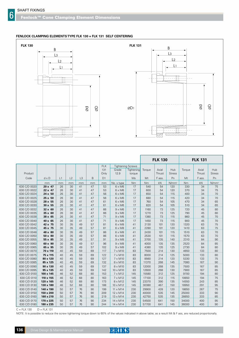
FENLOCK CLAMPING ELEMENTS TYPE FLK 130 + FLK 131 SELF CENTERING
FLK 130 FLK 131
FLK 130 FLK 131
Fenlock™ Cone Clamping Element Dimensions
SH
AFT
FIX
ING
SS
ecti
on
SHAFT FIXINGS 6
Drive Design & Maintenance Manual 137
Dimensions Pre-load Total Torque Axial Distance W Hub Product force force thrust before tightening * Stress
Code d x D B L1 Pt Pa Mt F ass 1 2 3 4 Pn mm mm mm N N Nm kN mm mm mm mm N/mm2
630T0006 6 x 9 4.5 3.7 – 3800 2 0.84 2.5 2.5 3.0 4.0 75 630T0007 7 x 10 4.5 3.7 – 3900 3 0.86 2.5 2.5 3.0 4.0 70 630T0008 8 x 11 4.5 3.7 – 5300 5 1.17 2.5 2.5 3.0 4.0 90 630T0009 9 x 12 4.5 3.7 7650 15600 8 1.76 2.5 2.5 3.0 4.0 105 630T0010 10 x 13 4.5 3.7 7000 15600 10 1.91 2.5 2.5 3.0 4.0 105 630T0012 12 x 15 4.5 3.7 7000 15600 11 1.91 2.5 2.5 3.0 4.0 90 630T0013 13 x 16 4.5 3.7 6500 15600 13 2.02 2.5 2.5 3.0 4.0 90 630T0014 14 x 18 6.3 5.3 11000 25400 22 3.18 3.5 3.5 4.5 5.5 90 630T0015 15 x 19 6.3 5.3 10800 25400 24 3.24 3.5 3.5 4.5 5.5 85 630T0016 16 x 20 6.3 5.3 10000 25400 27 3.42 3.5 3.5 4.5 5.5 85 630T0017 17 x 21 6.3 5.3 9600 25400 30 3.51 3.5 3.5 4.5 5.5 85 630T0018 18 x 22 6.3 5.3 9150 25400 32 3.61 3.5 3.5 4.5 5.5 80 630T0019 19 x 24 6.3 5.3 12500 36000 49 5.22 3.5 3.5 4.5 5.5 110 630T0020 20 x 25 6.3 5.3 12000 36000 53 5.33 3.5 3.5 4.5 5.5 105 630T0022 22 x 26 6.3 5.3 9000 36000 66 6.00 3.5 3.5 4.5 5.5 115 630T0024 24 x 28 6.3 5.3 8400 36000 73 6.13 3.5 3.5 4.5 5.5 110 630T0025 25 x 30 6.3 5.3 10000 36000 72 5.77 3.5 3.5 4.5 5.5 95 630T0028 28 x 32 6.3 5.3 7500 36000 88 6.33 3.5 3.5 4.5 5.5 100 630T0030 30 x 35 6.3 5.3 8600 36000 91 6.08 3.5 3.5 4.5 5.5 85 630T0032 32 x 36 6.3 5.3 7900 45000 131 8.24 3.5 3.5 4.5 5.5 115 630T0035 35 x 40 7.0 6.0 10000 54000 171 9.77 3.5 3.5 4.5 5.5 110 630T0036 36 x 42 7.0 6.0 11700 54000 169 9.39 3.5 3.5 4.5 5.5 100 630T0038 38 x 44 7.0 6.0 11000 54000 181 9.55 3.5 3.5 4.5 5.5 95 630T0040 40 x 45 8.0 6.6 13900 66000 231 11.57 3.5 4.5 5.5 6.5 105 630T0042 42 x 48 8.0 6.6 15550 66000 235 11.22 3.5 4.5 5.5 6.5 95 630T0045 45 x 52 10.0 8.6 28300 99000 353 15.71 3.5 4.5 5.5 6.5 95 630T0048 48x 55 10.0 8.6 24700 132000 572 23.84 3.5 4.5 5.5 6.5 135 630T0050 50 x 57 10.0 8.6 23600 132000 602 24.08 3.5 4.5 5.5 6.5 130 630T0055 55 x 62 10.0 8.6 21700 132000 670 24.35 3.5 4.5 5.5 6.5 125 630T0060 60 x 68 12.0 10.4 27500 157200 860 28.60 3.5 4.5 5.5 7.0 110 630T0063 63 x 71 12.0 10.4 26500 157200 910 28.80 3.5 4.5 5.5 7.0 105 630T0065 65 x 73 12.0 10.4 25500 157200 950 29.20 3.5 4.5 5.5 7.0 100 630T0070 70 x 79 14.0 12.2 31000 209600 1380 39.40 3.5 5.0 6.5 7.5 110 630T0071 71 x 80 14.0 12.2 31000 209600 1400 39.40 3.5 5.0 6.5 7.5 110 630T0075 75 x 84 14.0 12.2 34700 209600 1450 38.60 3.5 5.0 6.5 7.5 100 630T0080 80 x 91 17.0 15.0 48000 290000 2200 55.00 4.0 6.0 6.5 8.0 105 630T0085 85 x 96 17.0 15.0 45500 305000 2400 56.40 4.0 6.0 6.5 8.0 105 630T0090 90 x 101 17.0 15.0 43600 320000 2730 60.50 4.0 6.0 6.5 8.0 105 630T0095 95 x 106 17.0 15.0 41300 330000 3050 64.20 4.0 6.0 6.5 8.0 110 630T0100 100 x 114 21.0 18.7 61000 445000 4200 84.00 5.0 6.0 7.0 9.0 105 630T0110 110 x 124 21.0 18.7 66000 485000 5150 93.60 5.0 6.0 7.0 9.0 105 630T0120 120 x 134 21.0 18.7 60300 510000 6050 100.80 5.0 6.0 7.0 9.0 105 630T0130 130 x 148 28.0 25.3 96300 765000 9600 147.60 5.0 7.0 9.0 11.0 105 630T0140 140 x 158 28.0 25.3 89000 800500 11000 158.50 6.0 7.0 9.0 11.0 105 630T0160 160 x 178 28.0 25.3 78600 900000 14600 182.50 6.0 7.0 9.0 11.0 110 630T0170 170 x 191 33.0 30.0 117400 1160000 19500 229.00 7.0 9.0 10.0 12.0 105 630T0180 180 x 201 33.0 30.0 111300 1200000 21300 236.00 7.0 9.0 10.0 12.0 105 630T0190 190 x 211 33.0 30.0 105000 1260000 24200 255.00 7.0 9.0 10.0 12.0 110 630T0200 200 x 224 38.0 34.8 134200 1550000 31000 310.00 7.0 8.0 11.0 13.0 105 630T0210 210 x 234 38.0 34.8 127200 1610000 35000 333.00 7.0 9.0 11.0 13.0 110 630T0220 220 x 244 38.0 34.8 122100 1690000 38000 345.00 7.0 9.0 11.0 13.0 110 630T0230 230 x 257 43.0 39.5 164500 2000000 47000 408.00 7.0 10.0 12.0 14.0 105 630T0240 240 x 267 43.0 39.5 157400 2250000 51000 425.00 7.0 10.0 12.0 14.0 110 630T0250 250 x 280 48.0 44.0 190000 2060000 52000 415.00 7.0 10.0 13.0 16.0 89 630T0260 260 x 290 48.0 44.0 182000 2132000 56500 435.00 7.0 10.0 13.0 16.0 89 630T0270 270 x 300 48.0 44.0 177000 2207000 61000 450.00 7.0 10.0 13.0 16.0 89 630T0280 280 x 313 53.0 49.0 206000 2536000 72500 520.00 7.0 11.0 14.0 17.0 89 630T0290 290 x 323 53.0 49.0 222000 2632000 77500 535.00 7.0 11.0 14.0 17.0 89 630T0300 300 x 333 53.0 49.0 214000 2704000 83000 555.00 7.0 11.0 14.0 17.0 89 630T0320 320 x 360 65.0 59.0 292000 3492000 114000 710.00 10.0 15.0 20.0 25.0 89 630T0340 340 x 380 65.0 59.0 272000 3672000 128500 755.00 10.0 15.0 20.0 25.0 89 630T0360 360 x 400 65.0 59.0 258000 3858000 144000 800.00 10.0 15.0 20.0 25.0 90 630T0380 380 x 420 65.0 59.0 269000 4069000 160500 845.00 10.0 15.0 20.0 25.0 90 630T0400 400 x 440 65.0 59.0 256000 4256000 178000 890.00 10.0 15.0 20.0 25.0 90 630T0420 420 x 460 65.0 59.0 244000 4444000 196000 935.00 10.0 15.0 20.0 25.0 90 630T0440 440 x 480 65.0 59.0 234000 4633000 215000 980.00 10.0 15.0 20.0 25.0 90 630T0460 460 x 500 65.0 59.0 224000 4824000 235000 1020.00 10.0 15.0 20.0 25.0 91 630T0480 480 x 520 65.0 59.0 239000 5039000 256000 1070.00 10.0 15.0 20.0 25.0 91 630T0500 500 x 540 65.0 59.0 229000 5229000 278000 1110.00 10.0 15.0 20.0 25.0 91 630T0520 520 x 570 80.0 73.0 338000 6788000 372000 1430.00 12.0 18.0 24.0 30.0 91 630T0540 540 x 590 80.0 73.0 326000 7026000 400000 1480.00 12.0 18.0 24.0 30.0 91
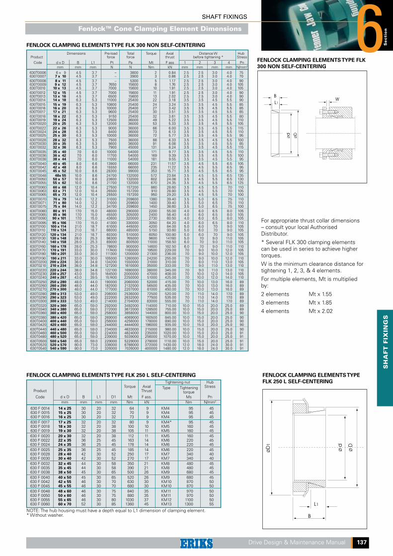
FENLOCK CLAMPING ELEMENTS TYPE FLK
300 NON SELF-CENTERING
For appropriate thrust collar dimensions – consult your local Authorised Distributor.
* Several FLK 300 clamping elements can be used in series to achieve higher torques.
W is the minimum clearance distance for tightening 1, 2, 3, & 4 elements.
For multiple elements, Mt is multiplied by:
2 elements Mt x 1.55
3 elements Mt x 1.85
4 elements Mt x 2.02
FENLOCK CLAMPING ELEMENTS TYPE FLK 250 L SELF-CENTERING
Tightening nut Hub Torque Axial Type Tightening Stress Product Thrust torque Code d x D B L1 D1 Mt F ass. Ms Pn mm mm mm mm Nm kN Nm N/mm2
630 F 0014 14 x 25 30 20 32 64 9 KM4 95 45 630 F 0015 15 x 25 30 20 32 70 9 KM4 95 45 630 F 0016 16 x 25 30 20 32 73 9 KM4 95 45 630 F 0017 17 x 25 32 20 32 80 9 KM4* 95 45 630 F 0018 18 x 30 32 20 38 100 10 KM5 160 45 630 F 0019 19 x 30 32 20 38 105 11 KM5 160 45 630 F 0020 20 x 30 32 20 38 112 11 KM5 160 45 630 F 0022 22 x 35 36 25 45 163 14 KM6 220 45 630 F 0024 24 x 35 36 25 45 178 14 KM6 220 45 630 F 0025 25 x 35 36 25 45 185 14 KM6 220 45 630 F 0028 28 x 40 42 30 52 250 17 KM7 340 40 630 F 0030 30 x 40 42 30 52 270 17 KM7 340 40 630 F 0032 32 x 45 44 30 58 350 21 KM8 480 45 630 F 0035 35 x 45 44 30 58 390 21 KM8 480 45 630 F 0038 38 x 50 45 30 65 500 26 KM9 680 45 630 F 0040 40 x 50 45 30 65 520 26 KM9 680 45 630 F 0042 42 x 55 46 30 70 630 30 KM10 870 50 630 F 0045 45 x 55 46 30 70 680 30 KM10 870 50 630 F 0048 48 x 60 46 30 75 840 35 KM11 970 50 630 F 0050 50 x 60 46 30 75 880 35 KM11 970 50 630 F 0055 55 x 65 46 30 80 1030 37 KM12 1100 50 630 F 0060 60 x 70 52 30 85 1360 45 KM13 1300 55
NOTE: The hub housing must have a depth equal to L1 dimension of clamping element.* Without washer.
FENLOCK CLAMPING ELEMENTS TYPE
FLK 250 L SELF-CENTERING
FENLOCK CLAMPING ELEMENTS TYPE FLK 300 NON SELF-CENTERING
Fenlock™ Cone Clamping Element Dimensions
SHAFT FIXINGS
6
138 Drive Design & Maintenance Manual
Dimensions Product Type Shaft Torque Axial Tightening Tightening Contact Code dia. Thrust screws torque Stress D I L d1 e 10.9 d dw Mt F ass. Ms Pw mm mm Nm kN mm mm mm mm mm No. x type Nm N/mm2
630 M 0014 11 30 6 14 12 50 9 38 7 11.0 23 2.00 4 x M5 4 186 13 70 10 630 M 0016 16 14 90 13 41 11 15.0 26 2.00 5 x M5 4 130 19 170 25 630 M 0024 24 20 210 27 50 14 19.5 36 2.75 6 x M5 4 286 21 250 29 24 300 29 630 M 0030 30 25 340 31 60 16 21.5 44 2.75 7 x M5 4 233 26 380 33 28 440 50 630 M 0036 36 30 570 58 72 18 23.5 52 2.75 5 x M6 12 307 31 630 58 32 620 64 630 M 0044 44 35 780 74 80 20 25.5 61 2.75 7 x M6 12 317 36 860 77 38 940 79 630 M 0050 50 40 1160 86 90 22 27.5 70 2.75 8 x M6 12 289 42 1380 92 42 1160 79 630 M 0055 55 45 1520 88 100 23 30.5 75 3.75 8 x M6 12 252 48 1880 97 48 1850 100 630 M 0062 62 50 2200 111 110 23 30.5 86 3.75 10 x M6 12 279 52 2400 117 50 2000 97 630 M 0068 68 55 2500 106 115 23 30.5 86 3.75 10 x M6 12 255 60 3150 120 55 2500 119 630 M 0075 75 60 3200 137 138 25 32.5 100 3.75 7 x M8 30 273 65 3950 155 60 3200 124 630 M 0080 80 65 3900 140 145 25 32.5 100 3.75 7 x M8 30 256 70 4600 158 65 4800 175 630 M 0085 85 70 6100 195 155 30 39.0 114 4.50 10 x M8 30 285 75 7400 216 65 4750 170 630 M 0090 90 70 6000 190 155 30 39.0 114 4.50 10 x M8 30 271 75 7250 210 70 6900 195 630 M 0100 100 75 7500 220 170 34 44.0 124 5.00 12 x M8 30 258 80 9000 240 75 7200 229 630 M 0110 110 80 9000 252 185 39 50.0 136 5.50 9 x M10 59 244 85 10800 262 80 7400 235 630 M 0115 115 85 9200 259 188 39 50.0 141 5.50 9 x M10 59 234 90 11100 269 80 10600 285 630 M 0120 120 85 13300 314 215 42 54.0 160 6.00 12 x M10 59 277 90 14500 340 85 11000 296 630 M 0125 125 90 13000 324 215 42 54.0 160 6.00 12 x M10 59 266 95 15000 352 90 11300 304 630 M 0130 130 95 13300 333 215 42 54.0 160 6.00 12 x M10 59 255 100 15400 362 95 15100 367 630 M 0140 140 100 17600 396 230 46 60.5 175 7.25 10 x M12 100 264 105 20100 425
FENLOCK CLAMPING ELEMENTS TYPE FLK 603 STD. VERSION
Tightening Screws
Torque Axial Grade Tightening Hub Product Thrust 12.9 torque Stress
Code d x D L1 L2 L3 B D1 Mt F ass. Ms Pn mm mm mm mm mm mm Nm kN No. x type Nm N/mm2
630B0006 6 x 14 10 18.5 21 24 25 12 4 3 x M3 2 80 630B0007 7 x 15 12 22.0 25 29 27 25 7 3 x M4 5 110 630B0008 8 x 15 12 22.0 25 29 27 29 7 3 x M4 5 110 630B0009 9 x 16 14 23.0 26 30 28 44 10 4 x M4 5 115 630B0010 10 x 16 14 23.0 26 30 28 49 10 4 x M4 5 115 630B0011 11 x 18 14 23.0 26 30 32 53 10 4 x M4 5 105 630B0012 12 x 18 14 23.0 26 30 32 58 10 4 x M4 5 105 630B0013 13 x 23 14 23.0 26 30 38 63 10 4 x M4 5 80 630B0014 14 x 23 14 23.0 26 30 38 68 10 4 x M4 5 80 630B0015 15 x 24 16 29.0 36 42 45 127 17 3 x M6 17 115 630B0016 16 x 24 16 29.0 36 42 45 136 17 3 x M6 17 115 630B0017 17 x 26 18 31.0 38 44 47 180 22 4 x M6 17 125 630B0018 18 x 26 18 31.0 38 44 47 200 22 4 x M6 17 125 630B0019 19 x 27 18 31.0 38 44 49 210 22 4 x M6 17 120 630B0020 20 x 28 18 31.0 38 44 50 220 22 4 x M6 17 115 630B0022 22 x 32 25 38.0 45 51 54 250 22 4 x M6 17 80 630B0024 24 x 34 25 38.0 45 51 56 270 22 4 x M6 17 75 630B0025 25 x 34 25 38.0 45 51 56 280 22 4 x M6 17 75 630B0028 28 x 39 25 38.0 45 51 61 465 33 6 x M6 17 97 630B0030 30 x 41 25 38.0 45 51 62 510 33 6 x M6 17 90 630B0032 32 x 43 25 38.0 45 51 65 540 33 6 x M6 17 90 630B0038 38 x 50 32 45.0 52 58 72 860 45 8 x M6 17 75 630B0040 40 x 53 32 45.0 52 58 75 900 45 8 x M6 17 70 630B0042 42 x 55 32 45.0 52 58 78 950 45 8 x M6 17 70 630B0045 45 x 59 45 62.0 70 78 86 1890 84 8 x M8 41 85 630B0048 48 x 62 45 62.0 70 78 87 2010 84 8 x M8 41 80 630B0050 50 x 65 45 62.0 70 78 92 2100 84 8 x M8 41 75 630B0055 55 x 71 55 72.0 80 88 98 2600 94 9 x M8 41 65 630B0060 60 x 77 55 72.0 80 88 104 2840 94 9 x M8 41 60 630B0065 65 x 84 55 72.0 80 88 111 3070 94 9 x M8 41 55 630B0070 70 x 90 65 86.0 96 106 119 5250 150 9 x M10 83 70 630B0075 75 x 95 65 86.0 96 106 126 5600 150 9 x M10 83 65 630B0080 80 x100 65 86.0 96 106 131 8020 200 12 x M10 83 80 630B0085 85 x106 65 86.0 96 106 137 8500 200 12 x M10 83 75 630B0090 90 x112 65 86.0 96 106 144 9000 200 12 x M10 83 75 630B0095 95 x120 65 86.0 96 106 149 11000 230 14 x M10 83 80 630B0100 100 x125 65 86.0 96 106 154 15000 300 18 x M10 83 95 630B0110 110 x140 90 114.0 128 140 180 16000 290 12 x M12 145 65 630B0120 120 x155 90 114.0 128 140 198 17500 290 12 x M12 145 55 630B0130 130 x165 90 114.0 128 140 208 25000 384 16 x M12 145 70
FLK 110
FLK 603
FENLOCK CLAMPING ELEMENTS TYPE FLK 110 SELF-CENTERING
Dimensions Product Type Shaft Torque Axial Tightening Tightening Contact Code dia. Thrust screws torque Stress D I L d1 e 10,9 d dw Mt F ass. Ms Pw mm mm Nm kN mm mm mm mm mm No. x type Nm N/mm2
105 22000 447 630 M 0155 155 110 25000 478 265 50 64.5 192 7.25 12 x M12 100 263 115 28000 509 110 22600 460 630 M 0160 160 115 25700 490 265 50 64.5 192 7.25 12 x M12 100 254 120 28800 520 115 31000 595 630 M 0165 165 120 35000 630 290 56 71.0 210 7.50 8 x M16 250 277 125 39000 655 120 31900 610 630 M 0170 170 125 36000 640 290 56 71.0 210 7.50 8 x M16 250 268 130 40100 670 125 36000 605 630 M 0175 175 130 41000 639 300 56 71.0 220 7.50 8 x M16 250 261 135 45000 675 130 37000 800 630 M 0180 180 135 42200 840 300 56 71.0 220 7.50 8 x M16 250 253 140 46300 885 135 52000 778 630 M 0185 185 140 57000 819 330 71 86.0 236 7.50 10 x M16 250 244 145 62000 861 140 53500 800 630 M 0190 190 145 58700 840 330 71 86.0 236 7.50 10 x M16 250 237 150 63800 885 140 65000 933 630 M 0195 195 150 76000 1025 350 71 86.0 246 7.00 12 x M16 250 277 155 81500 1071 150 74000 990 630 M 0200 200 155 80000 1035 350 71 86.0 246 7.00 12 x M16 250 270 160 86000 1080 160 95000 1190 630 M 0220 220 165 102000 1239 370 88 104.0 270 8.00 15 x M16 250 248 170 110000 1290 170 120000 1464 630 M 0240 240 180 138000 1576 405 92 109.0 295 8.00 12 x M20 490 272 190 156000 1675 190 164000 1760 630 M 0260 260 200 184000 1880 430 103 120.0 321 8.00 14 x M20 490 262 210 205000 2010 210 217000 2090 630 M 0280 280 220 244000 2220 460 114 134.0 346 10.00 16 x M20 490 251 230 270000 2350
FenLock Cone Clamping Element Dimensions
www.eriks.nl
AlkmaarSaffierstraat 31812 RM Alkmaar T (072) 514 17 17F (072) 514 16 25E [email protected]
AlmeloPlesmanweg 127602 PE AlmeloT (0546) 87 30 70 F (0546) 87 32 68 E [email protected]
AmsterdamDynamostraat 46-481014 BK Amsterdam-WestpoortT (020) 448 96 10 F (020) 613 77 65 E [email protected]
ArnhemPieter Calandweg 466827 BK Arnhem T (026) 362 92 44F (026) 361 00 63E [email protected]
Bergen op Zoom Van Konijnenburgweg 44 b4612 PL Bergen op Zoom T (0164) 27 55 44F (0164) 27 55 49E [email protected]
Delfzijl Deltaweg 309936 HK FarmsumT (0596) 63 38 20F (0596) 63 38 29E [email protected]
Den Haag Neckar 2 2491 BD Den Haag T (070) 381 84 84F (070) 381 84 36E [email protected]
DoetinchemHavenstraat 557005 AG DoetinchemT (0314) 34 37 20F (0314) 34 37 41E [email protected]
EdeGalvanistraat 346716 AE EdeT (0318) 43 96 14F (0318) 64 01 04E [email protected]
EerbeekLoubergweg 196961 EJ EerbeekT (0313) 67 95 00F (0313) 65 47 68E [email protected]
EindhovenDe Witbogt 22 a5652 AG EindhovenT (040) 291 19 00F (040) 291 19 09E [email protected]
EmmenWillem Schoutenstraat 11 b7825 VV EmmenT (0591) 66 80 00F (0591) 66 80 06E [email protected]
HengeloHassinkweg 16 7556 BV HengeloT (074) 291 57 57F (074) 291 59 39E [email protected]
HoornDe Factorij 35 d1689 AK ZwaagT (0229) 21 28 82F (0229) 21 93 74E [email protected]
GoudaMarconistraat 1172809 PG GoudaT (0182) 33 11 60F (0182) 37 82 02E [email protected]
GroningenRouaanstraat 89723 CD GroningenT (050) 368 49 99F (050) 368 49 98E [email protected]
LeeuwardenJames Wattstraat 19 8912 AS LeeuwardenT (058) 215 05 87F (058) 215 85 16E [email protected]
MaastrichtAmerikalaan 286199 AE Maastricht-AirportT (043) 604 91 80F (043) 363 87 28E [email protected] RijnmondShannonweg 33, Haven 50793197 LG Rotterdam-BotlekT (010) 231 34 00F (010) 296 96 18E [email protected]
RotterdamCaïrostraat 803047 BC RotterdamT (010) 245 50 55F (010) 262 00 38E [email protected]
RoermondAda Byronweg 116045 GM RoermondT (0475) 37 22 70F (0475) 37 23 05E [email protected]
TilburgEllen Pankhurststraat 95032 MD TilburgT (013) 571 45 61F (013) 570 06 42E [email protected]
ZwolleAmpèrestraat 278013 PT ZwolleT (038) 467 29 20F (038) 467 29 29E [email protected]
ERIKS Servicecenters
DordrechtKeerweer 413316 KA DordrechtT (078) 652 21 21F (078) 652 21 29E [email protected]
GroningenRouaanstraat 89723 CD GroningenT (050) 368 49 49F (050) 314 62 57E [email protected]
LeeuwardenJames Wattstraat 198912 AS LeeuwardenT (058) 294 50 50F (058) 213 24 71E [email protected]
RoermondAlbert Einsteinweg 8 6045 GX RoermondT (0475) 37 22 33F (0475) 32 75 40E [email protected]
RotterdamSevillaweg 75 3047 AL RotterdamT (010) 245 50 00 F (010) 262 06 22E [email protected]
SchoonhovenBroeikweg 252871 RM SchoonhovenT (0182) 30 34 56F (0182) 38 69 20E [email protected]
ERIKS vestigingenAandrijftechniek
Afdichtingstechniek | Stromingstechniek | Kunststoffen | Aandrijftechniek | Gereedschappen & Onderhoudsproducten